EP2312176A1 - Sealed rolling bearing - Google Patents
Sealed rolling bearing Download PDFInfo
- Publication number
- EP2312176A1 EP2312176A1 EP10014468A EP10014468A EP2312176A1 EP 2312176 A1 EP2312176 A1 EP 2312176A1 EP 10014468 A EP10014468 A EP 10014468A EP 10014468 A EP10014468 A EP 10014468A EP 2312176 A1 EP2312176 A1 EP 2312176A1
- Authority
- EP
- European Patent Office
- Prior art keywords
- seal
- wall
- radially
- bearing
- seal lip
- Prior art date
- Legal status (The legal status is an assumption and is not a legal conclusion. Google has not performed a legal analysis and makes no representation as to the accuracy of the status listed.)
- Granted
Links
- 238000005096 rolling process Methods 0.000 title claims abstract description 46
- 239000013013 elastic material Substances 0.000 claims description 8
- 229920000800 acrylic rubber Polymers 0.000 claims description 6
- 229920000058 polyacrylate Polymers 0.000 claims description 6
- 238000007789 sealing Methods 0.000 claims description 6
- 229920000459 Nitrile rubber Polymers 0.000 claims description 5
- 150000002148 esters Chemical class 0.000 claims description 4
- 230000003014 reinforcing effect Effects 0.000 claims 1
- XLYOFNOQVPJJNP-UHFFFAOYSA-N water Substances O XLYOFNOQVPJJNP-UHFFFAOYSA-N 0.000 abstract description 23
- 230000033228 biological regulation Effects 0.000 abstract description 3
- 230000000052 comparative effect Effects 0.000 description 18
- 238000003825 pressing Methods 0.000 description 17
- 238000012360 testing method Methods 0.000 description 17
- 230000003746 surface roughness Effects 0.000 description 16
- 238000010438 heat treatment Methods 0.000 description 14
- 238000005520 cutting process Methods 0.000 description 5
- 238000004519 manufacturing process Methods 0.000 description 5
- 230000000717 retained effect Effects 0.000 description 4
- 238000005422 blasting Methods 0.000 description 3
- 230000003247 decreasing effect Effects 0.000 description 3
- 239000004519 grease Substances 0.000 description 3
- 230000035515 penetration Effects 0.000 description 3
- 239000000126 substance Substances 0.000 description 3
- 230000001154 acute effect Effects 0.000 description 2
- 230000000694 effects Effects 0.000 description 2
- 230000005489 elastic deformation Effects 0.000 description 2
- 238000005242 forging Methods 0.000 description 2
- 239000003921 oil Substances 0.000 description 2
- 230000001105 regulatory effect Effects 0.000 description 2
- UFHFLCQGNIYNRP-UHFFFAOYSA-N Hydrogen Chemical compound [H][H] UFHFLCQGNIYNRP-UHFFFAOYSA-N 0.000 description 1
- 230000006835 compression Effects 0.000 description 1
- 238000007906 compression Methods 0.000 description 1
- 239000010725 compressor oil Substances 0.000 description 1
- 239000000428 dust Substances 0.000 description 1
- 229910052739 hydrogen Inorganic materials 0.000 description 1
- 239000001257 hydrogen Substances 0.000 description 1
- 238000005984 hydrogenation reaction Methods 0.000 description 1
- 230000008595 infiltration Effects 0.000 description 1
- 238000001764 infiltration Methods 0.000 description 1
- 239000000463 material Substances 0.000 description 1
- 238000000034 method Methods 0.000 description 1
- 239000000843 powder Substances 0.000 description 1
- 230000000087 stabilizing effect Effects 0.000 description 1
Images


Classifications
-
- F—MECHANICAL ENGINEERING; LIGHTING; HEATING; WEAPONS; BLASTING
- F16—ENGINEERING ELEMENTS AND UNITS; GENERAL MEASURES FOR PRODUCING AND MAINTAINING EFFECTIVE FUNCTIONING OF MACHINES OR INSTALLATIONS; THERMAL INSULATION IN GENERAL
- F16C—SHAFTS; FLEXIBLE SHAFTS; ELEMENTS OR CRANKSHAFT MECHANISMS; ROTARY BODIES OTHER THAN GEARING ELEMENTS; BEARINGS
- F16C33/00—Parts of bearings; Special methods for making bearings or parts thereof
- F16C33/72—Sealings
- F16C33/76—Sealings of ball or roller bearings
- F16C33/78—Sealings of ball or roller bearings with a diaphragm, disc, or ring, with or without resilient members
- F16C33/7816—Details of the sealing or parts thereof, e.g. geometry, material
- F16C33/782—Details of the sealing or parts thereof, e.g. geometry, material of the sealing region
- F16C33/7823—Details of the sealing or parts thereof, e.g. geometry, material of the sealing region of sealing lips
-
- F—MECHANICAL ENGINEERING; LIGHTING; HEATING; WEAPONS; BLASTING
- F16—ENGINEERING ELEMENTS AND UNITS; GENERAL MEASURES FOR PRODUCING AND MAINTAINING EFFECTIVE FUNCTIONING OF MACHINES OR INSTALLATIONS; THERMAL INSULATION IN GENERAL
- F16C—SHAFTS; FLEXIBLE SHAFTS; ELEMENTS OR CRANKSHAFT MECHANISMS; ROTARY BODIES OTHER THAN GEARING ELEMENTS; BEARINGS
- F16C33/00—Parts of bearings; Special methods for making bearings or parts thereof
- F16C33/30—Parts of ball or roller bearings
- F16C33/58—Raceways; Race rings
- F16C33/64—Special methods of manufacture
-
- F—MECHANICAL ENGINEERING; LIGHTING; HEATING; WEAPONS; BLASTING
- F16—ENGINEERING ELEMENTS AND UNITS; GENERAL MEASURES FOR PRODUCING AND MAINTAINING EFFECTIVE FUNCTIONING OF MACHINES OR INSTALLATIONS; THERMAL INSULATION IN GENERAL
- F16C—SHAFTS; FLEXIBLE SHAFTS; ELEMENTS OR CRANKSHAFT MECHANISMS; ROTARY BODIES OTHER THAN GEARING ELEMENTS; BEARINGS
- F16C33/00—Parts of bearings; Special methods for making bearings or parts thereof
- F16C33/72—Sealings
- F16C33/76—Sealings of ball or roller bearings
- F16C33/78—Sealings of ball or roller bearings with a diaphragm, disc, or ring, with or without resilient members
- F16C33/784—Sealings of ball or roller bearings with a diaphragm, disc, or ring, with or without resilient members mounted to a groove in the inner surface of the outer race and extending toward the inner race
- F16C33/7843—Sealings of ball or roller bearings with a diaphragm, disc, or ring, with or without resilient members mounted to a groove in the inner surface of the outer race and extending toward the inner race with a single annular sealing disc
- F16C33/7853—Sealings of ball or roller bearings with a diaphragm, disc, or ring, with or without resilient members mounted to a groove in the inner surface of the outer race and extending toward the inner race with a single annular sealing disc with one or more sealing lips to contact the inner race
-
- F—MECHANICAL ENGINEERING; LIGHTING; HEATING; WEAPONS; BLASTING
- F16—ENGINEERING ELEMENTS AND UNITS; GENERAL MEASURES FOR PRODUCING AND MAINTAINING EFFECTIVE FUNCTIONING OF MACHINES OR INSTALLATIONS; THERMAL INSULATION IN GENERAL
- F16C—SHAFTS; FLEXIBLE SHAFTS; ELEMENTS OR CRANKSHAFT MECHANISMS; ROTARY BODIES OTHER THAN GEARING ELEMENTS; BEARINGS
- F16C19/00—Bearings with rolling contact, for exclusively rotary movement
- F16C19/02—Bearings with rolling contact, for exclusively rotary movement with bearing balls essentially of the same size in one or more circular rows
- F16C19/04—Bearings with rolling contact, for exclusively rotary movement with bearing balls essentially of the same size in one or more circular rows for radial load mainly
- F16C19/06—Bearings with rolling contact, for exclusively rotary movement with bearing balls essentially of the same size in one or more circular rows for radial load mainly with a single row or balls
-
- F—MECHANICAL ENGINEERING; LIGHTING; HEATING; WEAPONS; BLASTING
- F16—ENGINEERING ELEMENTS AND UNITS; GENERAL MEASURES FOR PRODUCING AND MAINTAINING EFFECTIVE FUNCTIONING OF MACHINES OR INSTALLATIONS; THERMAL INSULATION IN GENERAL
- F16C—SHAFTS; FLEXIBLE SHAFTS; ELEMENTS OR CRANKSHAFT MECHANISMS; ROTARY BODIES OTHER THAN GEARING ELEMENTS; BEARINGS
- F16C19/00—Bearings with rolling contact, for exclusively rotary movement
- F16C19/02—Bearings with rolling contact, for exclusively rotary movement with bearing balls essentially of the same size in one or more circular rows
- F16C19/14—Bearings with rolling contact, for exclusively rotary movement with bearing balls essentially of the same size in one or more circular rows for both radial and axial load
- F16C19/18—Bearings with rolling contact, for exclusively rotary movement with bearing balls essentially of the same size in one or more circular rows for both radial and axial load with two or more rows of balls
- F16C19/181—Bearings with rolling contact, for exclusively rotary movement with bearing balls essentially of the same size in one or more circular rows for both radial and axial load with two or more rows of balls with angular contact
- F16C19/183—Bearings with rolling contact, for exclusively rotary movement with bearing balls essentially of the same size in one or more circular rows for both radial and axial load with two or more rows of balls with angular contact with two rows at opposite angles
- F16C19/184—Bearings with rolling contact, for exclusively rotary movement with bearing balls essentially of the same size in one or more circular rows for both radial and axial load with two or more rows of balls with angular contact with two rows at opposite angles in O-arrangement
-
- F—MECHANICAL ENGINEERING; LIGHTING; HEATING; WEAPONS; BLASTING
- F16—ENGINEERING ELEMENTS AND UNITS; GENERAL MEASURES FOR PRODUCING AND MAINTAINING EFFECTIVE FUNCTIONING OF MACHINES OR INSTALLATIONS; THERMAL INSULATION IN GENERAL
- F16C—SHAFTS; FLEXIBLE SHAFTS; ELEMENTS OR CRANKSHAFT MECHANISMS; ROTARY BODIES OTHER THAN GEARING ELEMENTS; BEARINGS
- F16C2240/00—Specified values or numerical ranges of parameters; Relations between them
- F16C2240/12—Force, load, stress, pressure
-
- F—MECHANICAL ENGINEERING; LIGHTING; HEATING; WEAPONS; BLASTING
- F16—ENGINEERING ELEMENTS AND UNITS; GENERAL MEASURES FOR PRODUCING AND MAINTAINING EFFECTIVE FUNCTIONING OF MACHINES OR INSTALLATIONS; THERMAL INSULATION IN GENERAL
- F16C—SHAFTS; FLEXIBLE SHAFTS; ELEMENTS OR CRANKSHAFT MECHANISMS; ROTARY BODIES OTHER THAN GEARING ELEMENTS; BEARINGS
- F16C2240/00—Specified values or numerical ranges of parameters; Relations between them
- F16C2240/30—Angles, e.g. inclinations
-
- F—MECHANICAL ENGINEERING; LIGHTING; HEATING; WEAPONS; BLASTING
- F16—ENGINEERING ELEMENTS AND UNITS; GENERAL MEASURES FOR PRODUCING AND MAINTAINING EFFECTIVE FUNCTIONING OF MACHINES OR INSTALLATIONS; THERMAL INSULATION IN GENERAL
- F16C—SHAFTS; FLEXIBLE SHAFTS; ELEMENTS OR CRANKSHAFT MECHANISMS; ROTARY BODIES OTHER THAN GEARING ELEMENTS; BEARINGS
- F16C2240/00—Specified values or numerical ranges of parameters; Relations between them
- F16C2240/40—Linear dimensions, e.g. length, radius, thickness, gap
Definitions
- the present invention relates to a sealed rolling bearing including contact seals sealing its bearing space defined between the inner and outer rings thereof.
- sealed rolling bearings In sealed rolling bearings, it is necessary to seal their bearing space defined between the inner and outer rings high seal performance to prevent leakage of grease from the bearing space and entry of foreign matter such as water and dust from outside. Therefore, sealed rolling bearings are used which have their bearing space sealed by contact seals having seal lips made of an elastic material and in sliding contact with the sliding contact surfaces formed on one of the inner and outer rings (as disclosed in Japanese utility model publication 7-10555 (Patent publication 1) in Figs. 1 , 2 ).
- the sealed rolling bearing disclosed in Patent publication 2 has a tip of the seal lip in sliding contact with a straight portion of the inner wall of the seal groove for stable contact. Specifically, the distance L from the outer end of a rounded portion extending from the bottom of the seal groove to the axially inner wall to the contact point is set to 0.35 mm ⁇ L ⁇ 3 mm.
- the sealed rolling bearing disclosed in Patent publication 3 has a seal lip extending beyond the metallic core and its axial thickness B is set to 0.2 mm to 0.4 mm. Also, the ratio of the radial length A of the seal lip to its axial thickness B is set to 4.5 ⁇ A/B ⁇ 7. Further, it proposes to adjust the rigidity of the seal lip to a suitable level, thus improving the followability of the seal lip on the sliding contact surface and ensuring stable contact of the seal lip.
- the ratio of the force P for pressing the seal lip against the sliding contact surface to the axial interference L of the seal lip is set to 2.9 to 9.8 N/mm and the interference L is set to 1 to 3% of the diameter of the balls as the rolling elements, thereby suppressing the elastic deformation of the elastic member resulting in the decrease of the seal performance and ensuring the seal performance.
- the bearing rings of rolling bearings such as inner and outer rings are manufactured following the steps shown in Fig. 16 . That is, while the raceways on which rolling elements roll are subjected to turning and super-finishing after heat treatment such as hardening, sliding contact surfaces with which the seal lips are brought in sliding contact are formed by turning not after but before heat treatment. After heat treatment, the sliding contact surfaces are not subjected to any kind of treatment.
- the sealed rolling bearing disclosed in Patent publication 4 prevents entry of foreign matter from the seal grooves by regulating the angle Y between the radially inner inclined surface and the bottom of the seal groove to 0 to 30 degrees. But in order to prevent entry of foreign matter from the seal grooves, it is important that the angle of the axially inner wall of the seal groove relative to the radially inner inclined surface be large. Even if the angle of the radially inner inclined surface relative to the bottom of the seal groove is regulated, expected seal effect cannot be always obtained. Also, with sealed rolling bearings in which the ratio of the seal lip pressing force P to the axial interference L and the axial interference L are specified, if the interference L is changed, the pressing force P, too, will change.
- the control of the interference L and the ratio P/L within the specified ranges is troublesome. Also, if the interference L is near its lower limit, the ratio P/L will be within a specified range even with a small pressing force P. This makes it impossible to ensure the seal performance. Further, because the interference L is specified relative to the diameter of the balls, this method is applicable only to ball bearings. Thus, this arrangement is not versatile.
- an object of the present invention is to ensure the seal performance of a sealed rolling bearing even if used in an environment where the bearing is exposed to water and mud, by stably keeping the tip of the seal lip of each contact seal in contact with a sliding contact surface such as an axially inner wall of a seal groove, and to ensure the seal performance with simple and versatile regulations.
- a sealed rolling bearing comprising an inner ring formed with two seal grooves in a radially outer periphery thereof, each of the two seal grooves having an axially inner wall and an axially outer wall, an outer ring, a plurality of rolling elements disposed in a bearing space defined between the inner and outer rings, and contact seals fixed to the outer ring and each having a seal lip made of an elastic material and having a free end thereof kept in sliding contact with the axially inner wall of one of the seal grooves, thereby sealing the bearing space, characterized in that the seal lip of each of the contact seals has the free end thereof kept in sliding contact with the axially inner wall along a line that is located radially inwardly of a radially outer edge of the axially outer wall.
- the free end of the seal lip of each of the contact seals preferably has an inner diameter that is smaller than the diameter of the radially outer edge of the axially outer wall.
- a sealed rolling bearing comprising an inner ring formed with two seal grooves in a radially outer periphery thereof, each of the two seal grooves having an axially inner wall, an outer ring, a plurality of rolling elements disposed in a bearing space defined between the inner and outer rings, and contact seals fixed to the outer ring and each having a seal lip made of an elastic material and having a free end thereof kept in sliding contact with the axially inner wall of one of the seal grooves, thereby sealing the bearing space, characterized in that the seal lip of each of the contact seals has a radially outer inclined surface inclined radially outwardly from the free end, and a radially inner inclined surface inclined radially outwardly from the free end, the radially outer inclined surface forming an angle ⁇ of 13 to 44 degrees with respect to the axially inner wall, the radially inner inclined surface forming an angle ß of 91 to 100 degrees with respect to the axially inner wall.
- the angle ⁇ between the axially inner wall of each seal groove and the radially outer inclined surface should be 13 to 44 degrees for the following reason. If it is less than 13 degrees, grease pushed out of the bearing space into the seal groove could get into the tip side of the seal lip by wedge effect. This might form a minute gap between the sliding surface and the free end the seal lip, thereby impairing the seal performance. If it is over 44 degrees, the free end of the seal lip would form an acute angle, thereby decreasing its rigidity and seal performance.
- the angle ß between the axially inner wall of each seal groove and the radially inner inclined surface should be 91 to 100 degrees for the following reason. If it is less than 91 degrees, foreign matter in the seal groove tends to get into between the free end of the seal lip and the sliding contact surface, thus forming a minute gap therebetween and decreasing the seal performance. If it is over 100 degrees, the free end of the seal lip would form an acute angle, thereby decreasing its rigidity and seal performance.
- a sealed rolling bearing comprising an inner ring, an outer ring, a plurality of rolling elements disposed in a bearing space defined between the inner and outer rings, and contact seals each having a seal lip made of an elastic material, the seal lip being pressed against one of two sliding contact surfaces formed on one of the inner and outer rings to seal the bearing space, characterized in that the force for pressing the seal lip against the sliding contact surface is set to not less than 1.6 N.
- seal sliding surface By forming the seal sliding surface by cutting after heat treatment including hardening, it is possible to provide smooth sliding contact surfaces by an inexpensive means without increasing the treating steps, thereby ensuring smooth contact of the seal lips on the sliding contact surfaces and ensuring the seal performance.
- the descaling treatment may be shot blasting or barrel grinding.
- the seal lips can reliably keep its heat resistance even when used in a hot environment of 150 degrees C or higher like rolling bearings used in electromagnetic clutches. Also, even if smeared with oil, the seal lips will stably exhibit its function.
- Hydrogenated nitrile rubber differs from ordinary nitrile rubber in that hydrogen is added to the unsaturated bond by hydrogenation. It has high heat resistance of 150 degrees C or over and superior chemical resistance. Even if smeared with oil such as compressor oil for air-conditioners, it can maintain stable performance. Also, ester-resistant acrylic rubber has higher chemical resistance than acrylic rubber while maintaining high heat resistance inherent to acrylic rubber. It has high heat resistance of 150 degrees C or and high chemical resistance.
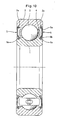
- Figs. 1 to 4 show the sealed rolling bearing according to the first embodiment of the present invention.
- this sealed rolling bearing is a double-row angular ball bearing which comprises an inner ring 1, an outer ring 2, balls 3 retained by a retainer 4 in two rows in a bearing space defined between the inner and outer rings 1 and 2, and contact seals 5 fixed in grooves 2a formed in the inner periphery of the outer ring 2 to seal the bearing space.
- each contact seal 5 comprises a metallic core 5a and an elastic member 5b having an axially inwardly extending seal lip 5c on its inner periphery.
- the seal lip 5c Before being mounted on the bearing, the seal lip 5c has, at its axially inner free end, an inner diameter D L that is smaller than the maximum diameter D I of an axially outer wall 1b of a seal groove 1a formed in the outer periphery of the inner ring 1.
- the difference between D L and D I is set to be no more than 0.2 mm so that the contact seals 5 can be easily mounted on the bearing.
- the elastic member 5b of each contact seal 5 is made of hydrogenated nitrile rubber or ester-resistant acrylic rubber in this embodiment and any of the following embodiments.
- Double-row angular ball bearings of the above-described type were mounted on a rotary tester in an environment where the bearings were intermittently hit by flying foreign matter such as water and mud to determine the amount of foreign matter that penetrates into the bearing space while changing the radial distance ⁇ of the contact point between the seal lip 5c and the inner wall 1c of the seal groove 1a from the radially outer edge of the axially outer wall 1b.
- the contact point between the seal lip 5c and the inner wall 1c was radially inwardly spaced apart by 0.1 mm and 0.05 mm (Examples of the invention), and radially outwardly spaced apart by 0.0 mm, 0.05 mm and 0.1 mm (Comparative Examples), from the radially outer edge of the axially outer wall 1b.
- the amount of foreign matter that had penetrated into the bearing space was determined from the difference W in the mass of the bearing before and after the test. The test was conducted under the following conditions:
- Fig. 4 shows the test results.
- the increase W in the mass of the bearing was remarkable.
- the increase W was low. This means that foreign matter scarcely penetrated into the bearing space.
- Figs. 5 and 6 show the second embodiment.
- this sealed rolling bearing is a deep groove ball bearing which includes an inner ring 1, an outer ring 2, balls 3 retained in a single row by a retainer 4 in a bearing space defined between the inner and outer rings 1 and 2, and contact seals 5 fixed in grooves 2a formed in the inner periphery of the outer ring 2 to seal the bearing space.
- each contact seal 5 comprises a metallic core 5a and an elastic member 5b having an axially inwardly extending seal lip 5c formed at its inner periphery.
- the seal lip 5c has a radially outer inclined surface 6a sloping radially outwardly from its tip, which is kept in sliding contact with the axially inner wall 1c of the seal groove 1a, and a radially inner inclined surface 6b sloping radially outwardly from its tip.
- the angle ⁇ of the inclined surface 6a to the inner wall 1c is set to 13 to 44 degrees.
- the angle ß of the inclined surface 6b to the inner wall 1c is set to 91 to 100 degrees.
- Sealed deep groove ball bearings of the above-described type having different combinations of the angles ⁇ and ß were mounted on a rotary tester in an environment in which the bearings were splashed with muddy water to check how muddy water infiltrated into the bearing space.
- Table 1 shows the test results.
- the angle Y of the radially inner inclined surface to the bottom of the seal groove, too, is indicated as a reference value.
- the angle Y is specified to 0 to 30 degrees in Patent publication 4.
- any of Examples A, B and C of the invention in which the angle ⁇ was 13 to 44 degrees and the angle ß was 91 to 100 degrees, no infiltration of muddy water into the bearing space was observed. Thus, they showed high resistance to muddy water.
- Comparative Examples A, B, C and D in which one or both of the angles ⁇ and ß were not within the above ranges, large amounts of muddy water penetrated into the bearing space. Thus, resistance to muddy water was inferior.
- Comparative Example D meets the ranges for the angles ⁇ and Y specified in Patent publication 4, the resistance to muddy water was poor.
- Figs. 7 to 9 show the third embodiment.
- this sealed rolling bearing is a deep groove ball bearing including an inner ring 1, an outer ring 2, balls 3 retained by a retainer 4 in a bearing space defined between the inner and outer rings 1 and 2, and contact seals 5 fixed in grooves 2a formed in the inner periphery of the outer ring 2 to seal the bearing space.
- the contact seal 5 comprises a metallic core 5a and an elastic member 5b.
- the elastic member 5b has a neck portion 5d extending beyond the metallic core 5a and a seal lip 5c at its tip.
- the seal lip 5c is pressed axially against an axially inner wall 1c of a seal groove 1a formed in the outer periphery of the inner ring 1, with a force P not less than 1.6 N.
- the surface roughness Rmax of the axially inner wall 1c of the seal groove 1a as the sliding contact surface is set to not more than 1.2 micrometers.
- sealed deep groove ball bearings of the type shown in Figs. 7A and 7B were prepared in which the seal lip pressing force P was set to not less than 1.6N.
- similar sealed deep groove ball bearings were prepared in which the ratio of the pressing force P to the axial interference L was 4.8 to 8.8 N/mm and the pressing force was not more than 1.6 N.
- the seal lip pressing force P was determined by horizontally mounting the outer ring 2 on a rack 12 of a compression tester 11 with one of the contact seals 5 fitted on the outer ring 2 (see Fig.
- the surface roughness Rmax of the sliding contact surface was not more than 1.2 micrometers.
- Fig. 9 shows the results of the test.
- the seal lip pressing force P was not less than 1.6 N, although the ratio a/b, which corresponds to the ratio A/B (A: radial length of the seal lip; B: its axial thickness), was not within the range specified in Patent publication 3, the increase W in the mass of the bearing was not remarkable. This means that Examples of the invention have excellent seal performance.
- the pressing force P was less than 1.6 N, although the ratio of the seal lip pressing force P to the axial interference L was within the range specified in Patent publication 4, the increase in the mass of the bearing was remarkable. This means that no sufficient seal performance is obtained.
- Figs. 10 to 13 show the fourth embodiment.
- this sealed rolling bearing is a deep groove ball bearing comprising an inner ring 1, an outer ring 2, balls 3 retained by a retainer 4 in a bearing space defined between the inner and outer rings 1 and 2, and contact seals 5 fixed in grooves 2a formed in the inner periphery of the outer ring 2 to seal the bearing space.
- each contact seal 5 has two seal lips 5c 1 and 5c 2 at its radially inner end.
- the axially inner seal lip 5c 1 is kept in sliding contact with an axially inner wall 1c of a seal groove 1a formed in the outer periphery of the inner ring 1.
- the axially outer seal lip 5c 2 is in sliding contact with the radially outer edge of an axially outer wall 1b of the seal groove 1a.
- a major portion of the inner ring except its portions where the seal grooves 1a are to be formed is formed by forging and turning the stock for the inner ring, and the stock is subjected to heat treatment including hardening and width grinding.
- the seal grooves 1a are formed by cutting.
- the subsequent steps are the same as conventional steps (shown in Fig. 16 ) for manufacturing bearing rings. Specifically, a raceway is formed by grinding, the inner periphery is ground, and the raceway is super-finished.
- Fig. 13A shows the surface roughness of the sliding contact surfaces formed by cutting after hardening (Examples of the invention).
- Fig. 13B shows the surface roughness of the sliding contact surfaces not subjected to descaling treatment after heat treatment as in the prior art (Comparative Examples).
- the surface roughness of the sliding contact surfaces is 2.60 micrometers in terms of Rmax for Comparative Examples, whereas the surface roughness of the sliding contact surfaces is 1.03 micrometers in terms of Rmax for Examples of the invention, which are formed by cutting after hardening.
- Figs. 14 and 15 show the fifth embodiment.
- the fifth embodiment is a deep groove ball bearing of the same type as the fourth embodiment.
- Its inner ring is manufactured as shown in Fig. 14 .
- the stock for the inner ring 1 is formed by forging and turning and subjected to heat treatment such as hardening.
- the sliding contact surface formed on the axially inner wall 1c of each seal groove 1a and the sliding contact surface on the radially outer edge of the axially outer wall 1b are subjected to descaling treatment to remove scales formed during heat treatment.
- the subsequent steps are the same as the conventional manufacturing steps for bearing rings shown in Fig. 16 .
- Fig. 15A is a graph showing the surface roughness of the sliding contact surfaces subjected to shot blasting as descaling treatment (Examples of the invention).
- the graph shows that Examples of the invention, which were subjected to shot blasting, have very smooth sliding contact surfaces with the surface roughness of 0.79 micrometers in terms of Rmax in comparison with, as shown in Fig. 13B , the surface roughness of the sliding contact surfaces of Comparative Examples, which were not subjected to descaling treatment after heat treatment, that is, 2.60 micrometers in terms of Rmax.
- Fig. 15B is a graph showing the surface roughness of the sliding contact surfaces of another Example of the invention, which was subjected to barrel grinding as descaling treatment.
- the surface roughness of the sliding contact surfaces was 1.30 micrometers in terms of Rmax, which is less than 2.0 micrometers as in Example shown in Fig. 15A .
- the sealed rolling bearing in any of the above embodiments is a double-row angular ball bearing or a deep groove ball bearing with the contact seals fixed to the outer ring
- the present invention is applicable to other ball bearings and other types of rolling bearings such as roller bearings.
- the contact seals may be fixed to the inner ring.
Abstract
The seal lip (5c) of each of said contact seals (5) has a radially outer inclined surface (6a) inclined radially outwardly from its free end, and a radially inner inclined surface (6b) inclined radially outwardly from said free end, said radially outer inclined surface (6a) forming an angle α of 13 to 44 degrees with respect to said axially inner wall (1c), said radially inner inclined surface (6b) forming an angle β of 91 to 100 degrees with respect to said axially inner wall (1c). Thus, high resistance to muddy water can be achieved. Therefore, stable contact of the seal lip with the axially inner wall of the seal groove is ensured, thereby achieving good seal performance.
Description
- The present invention relates to a sealed rolling bearing including contact seals sealing its bearing space defined between the inner and outer rings thereof.
- In sealed rolling bearings, it is necessary to seal their bearing space defined between the inner and outer rings high seal performance to prevent leakage of grease from the bearing space and entry of foreign matter such as water and dust from outside. Therefore, sealed rolling bearings are used which have their bearing space sealed by contact seals having seal lips made of an elastic material and in sliding contact with the sliding contact surfaces formed on one of the inner and outer rings (as disclosed in Japanese utility model publication
7-10555 Figs. 1 ,2 ). - Among such sealed rolling bearings, ones for use in pulleys for vehicle accessories and electromagnetic clutches for compressors of air-conditioners often have their contact seals secured to the outer ring and have the seal lips of the contact seals in sliding contact with axially inner walls of seal grooves formed in the outer periphery of the inner ring to seal the bearing space defined between the inner and outer rings (see e.g. Patent publication 2: Japanese patent publication
2003-35319A Fig. 1 ); Patent publication 3: Japanese patent3062673 Figs. 1 and2 ); and Patent publication 4: Japanese patent publication2001-140907A Figs. 1-4 )). Usually, the axially outer wall opposite to the inner wall of each seal groove is made to have a radial height lower than the radial height of the axially inner wall for easy mounting of the contact seals into the bearing. - The sealed rolling bearing disclosed in
Patent publication 2 has a tip of the seal lip in sliding contact with a straight portion of the inner wall of the seal groove for stable contact. Specifically, the distance L from the outer end of a rounded portion extending from the bottom of the seal groove to the axially inner wall to the contact point is set to 0.35 mm < L < 3 mm. - The sealed rolling bearing disclosed in
Patent publication 3 has a seal lip extending beyond the metallic core and its axial thickness B is set to 0.2 mm to 0.4 mm. Also, the ratio of the radial length A of the seal lip to its axial thickness B is set to 4.5 ≤ A/B ≤ 7. Further, it proposes to adjust the rigidity of the seal lip to a suitable level, thus improving the followability of the seal lip on the sliding contact surface and ensuring stable contact of the seal lip. - The sealed rolling bearing disclosed in
Patent publication 4 has a seal lip which is in sliding contact with the axially inner wall of the seal groove and has a radially outer inclined surface inclined radially outwardly from its tip, and a radially inner inclined surface inclined toward the bottom of the seal groove from its tip. Also, the angle a between the axially inner wall of the seal groove and the radially outer inclined surface is set to 10 to 45 degrees and the angle Y between the bottom of the seal groove and the radially inner inclined surface is set to 0 to 30 degrees to suppress elastic deformation of the seal lip by grease pushed out of the bearing space into the seal groove, and to prevent entry of foreign matter from the bottom of the seal groove into the bearing space. Also, the ratio of the force P for pressing the seal lip against the sliding contact surface to the axial interference L of the seal lip is set to 2.9 to 9.8 N/mm and the interference L is set to 1 to 3% of the diameter of the balls as the rolling elements, thereby suppressing the elastic deformation of the elastic member resulting in the decrease of the seal performance and ensuring the seal performance. - Including the above-mentioned sealed type, the bearing rings of rolling bearings such as inner and outer rings are manufactured following the steps shown in
Fig. 16 . That is, while the raceways on which rolling elements roll are subjected to turning and super-finishing after heat treatment such as hardening, sliding contact surfaces with which the seal lips are brought in sliding contact are formed by turning not after but before heat treatment. After heat treatment, the sliding contact surfaces are not subjected to any kind of treatment. - The sealed rolling bearing disclosed in
Patent publication 2 has the seal lip of each contact seal kept in contact with the axially inner wall of the seal groove in a stable state under a calm environment where nothing scatters. But when used in an environment where the bearing is exposed to scattered water and mud, such scattered water and mud may directly hit the tip of the seal lip because, as mentioned above, the axially outer wall of the seal groove has a radial height lower than the axially inner wall. Therefore, the contact of the tip of the seal lip with the axially inner wall of the seal groove becomes unstable, thus lowering the seal performance of the contact seals. - With sealed rolling bearings having seal lips of a size set to provide proper rigidity, e.g. the one disclosed in
Patent publication 3, the interference of the seal lip is not specified either directly or indirectly. Therefore, seal performance cannot be ensured reliably. Also, the shape of the seal lip cannot be defined because the axial thickness B is not uniform, like the one disclosed inPatent publication 4. - The sealed rolling bearing disclosed in
Patent publication 4 prevents entry of foreign matter from the seal grooves by regulating the angle Y between the radially inner inclined surface and the bottom of the seal groove to 0 to 30 degrees. But in order to prevent entry of foreign matter from the seal grooves, it is important that the angle of the axially inner wall of the seal groove relative to the radially inner inclined surface be large. Even if the angle of the radially inner inclined surface relative to the bottom of the seal groove is regulated, expected seal effect cannot be always obtained. Also, with sealed rolling bearings in which the ratio of the seal lip pressing force P to the axial interference L and the axial interference L are specified, if the interference L is changed, the pressing force P, too, will change. Therefore, the control of the interference L and the ratio P/L within the specified ranges is troublesome. Also, if the interference L is near its lower limit, the ratio P/L will be within a specified range even with a small pressing force P. This makes it impossible to ensure the seal performance. Further, because the interference L is specified relative to the diameter of the balls, this method is applicable only to ball bearings. Thus, this arrangement is not versatile. - Therefore, an object of the present invention is to ensure the seal performance of a sealed rolling bearing even if used in an environment where the bearing is exposed to water and mud, by stably keeping the tip of the seal lip of each contact seal in contact with a sliding contact surface such as an axially inner wall of a seal groove, and to ensure the seal performance with simple and versatile regulations.
- According to the present invention, there is provided a sealed rolling bearing comprising an inner ring formed with two seal grooves in a radially outer periphery thereof, each of the two seal grooves having an axially inner wall and an axially outer wall, an outer ring, a plurality of rolling elements disposed in a bearing space defined between the inner and outer rings, and contact seals fixed to the outer ring and each having a seal lip made of an elastic material and having a free end thereof kept in sliding contact with the axially inner wall of one of the seal grooves, thereby sealing the bearing space, characterized in that the seal lip of each of the contact seals has the free end thereof kept in sliding contact with the axially inner wall along a line that is located radially inwardly of a radially outer edge of the axially outer wall.
- By bringing the free end of the seal lip of each contact seal into contact with the radially inner wall of the seal groove along a line located radially inwardly of the radially outer edge of the axially outer wall of the seal groove opposite to the inner wall, scattered water or mud will not directly hit the free end of the seal lip. Also, even if used in an environment where the bearing is exposed to scattered water and mud, stable contact of the tip of the seal lip on the axially inner wall of the seal groove as the sliding contact surface is ensured, so that sufficient seal performance is obtained.
- Before being fitted in the rolling bearing, the free end of the seal lip of each of the contact seals preferably has an inner diameter that is smaller than the diameter of the radially outer edge of the axially outer wall.
- From another aspect of the invention, there is provided a sealed rolling bearing comprising an inner ring formed with two seal grooves in a radially outer periphery thereof, each of the two seal grooves having an axially inner wall, an outer ring, a plurality of rolling elements disposed in a bearing space defined between the inner and outer rings, and contact seals fixed to the outer ring and each having a seal lip made of an elastic material and having a free end thereof kept in sliding contact with the axially inner wall of one of the seal grooves, thereby sealing the bearing space, characterized in that the seal lip of each of the contact seals has a radially outer inclined surface inclined radially outwardly from the free end, and a radially inner inclined surface inclined radially outwardly from the free end, the radially outer inclined surface forming an angle α of 13 to 44 degrees with respect to the axially inner wall, the radially inner inclined surface forming an angle ß of 91 to 100 degrees with respect to the axially inner wall.
- The angle α between the axially inner wall of each seal groove and the radially outer inclined surface should be 13 to 44 degrees for the following reason. If it is less than 13 degrees, grease pushed out of the bearing space into the seal groove could get into the tip side of the seal lip by wedge effect. This might form a minute gap between the sliding surface and the free end the seal lip, thereby impairing the seal performance. If it is over 44 degrees, the free end of the seal lip would form an acute angle, thereby decreasing its rigidity and seal performance.
- The angle ß between the axially inner wall of each seal groove and the radially inner inclined surface should be 91 to 100 degrees for the following reason. If it is less than 91 degrees, foreign matter in the seal groove tends to get into between the free end of the seal lip and the sliding contact surface, thus forming a minute gap therebetween and decreasing the seal performance. If it is over 100 degrees, the free end of the seal lip would form an acute angle, thereby decreasing its rigidity and seal performance.
- From still another aspect of the invention, there is provided a sealed rolling bearing comprising an inner ring, an outer ring, a plurality of rolling elements disposed in a bearing space defined between the inner and outer rings, and contact seals each having a seal lip made of an elastic material, the seal lip being pressed against one of two sliding contact surfaces formed on one of the inner and outer rings to seal the bearing space, characterized in that the force for pressing the seal lip against the sliding contact surface is set to not less than 1.6 N.
- By setting the force for pressing the seal lip against the seal sliding surface to not less than 1.6 N, only the pressing force is restricted while including the seal lip interference indirectly, thereby ensuring stable contact of the seal lip on the sliding contact surface and achieving high seal performance of the sealed rolling bearing reliably by simple and versatile regulations.
- Preferably, each of the sliding contact surfaces is formed on a side wall of one of two seal grooves formed in an outer periphery of the inner ring, the seal lip of each of the contact seals being pressed against one of the sliding contact surfaces in an axial direction.
- From a further aspect of the invention, there is provided a sealed rolling bearing comprising an inner ring, an outer ring, a plurality of rolling elements disposed in a bearing space defined between the inner and outer rings, and contact seals each having a seal lip made of an elastic material and kept in sliding contact with one of two sliding contact surfaces formed on one of the inner and outer rings, the inner and outer rings being subjected to heat treatment including hardening, characterized in that the sliding contact surfaces are formed by cutting the one of the inner and outer rings after the heat treatment.
- By forming the seal sliding surface by cutting after heat treatment including hardening, it is possible to provide smooth sliding contact surfaces by an inexpensive means without increasing the treating steps, thereby ensuring smooth contact of the seal lips on the sliding contact surfaces and ensuring the seal performance.
- From yet another aspect of the invention, there is provided a sealed rolling bearing comprising an inner ring, an outer ring, a plurality of rolling elements disposed in a bearing space defined between the inner and outer rings, and contact seals each having a seal lip made of an elastic material and kept in sliding contact with one of two sliding contact surfaces formed on one of the inner and outer rings, the inner and outer rings being subjected to heat treatment, characterized in that the sliding contact surfaces are subjected to descaling treatment to remove scales formed during the heat treatment.
- By subjecting the sliding contact surfaces to descaling treatment to remove scales formed during the heat treatment, it is possible to make the sliding contact surfaces sufficiently smooth to prevent a decrease in seal performance and an increase in torque loss.
- The descaling treatment may be shot blasting or barrel grinding.
- By restricting the surface roughness of the sliding contact surfaces to not more than 2.0 micrometers, preferably not more than 1.2 micrometers in terms of Rmax, it is possible to prevent an increase in torque loss caused by friction with the seal lips and suppress the wear of the seal lip, thereby stabilizing the seal lip pressing force.
- By using hydrogenated nitrile rubber or ester-resistant acrylic rubber as the material for the elastic member forming the seal lips, the seal lips can reliably keep its heat resistance even when used in a hot environment of 150 degrees C or higher like rolling bearings used in electromagnetic clutches. Also, even if smeared with oil, the seal lips will stably exhibit its function.
- Hydrogenated nitrile rubber differs from ordinary nitrile rubber in that hydrogen is added to the unsaturated bond by hydrogenation. It has high heat resistance of 150 degrees C or over and superior chemical resistance. Even if smeared with oil such as compressor oil for air-conditioners, it can maintain stable performance. Also, ester-resistant acrylic rubber has higher chemical resistance than acrylic rubber while maintaining high heat resistance inherent to acrylic rubber. It has high heat resistance of 150 degrees C or and high chemical resistance.
- Other features and objects of the present invention will become apparent from the following description made with reference to the accompanying drawings, in which:
-
Fig. 1 is a vertical sectional view of a sealed rolling bearing of a first embodiment; -
Fig. 2 is a sectional view of the same before contact seals are mounted in the bearing; -
Fig. 3 is a partial enlarged sectional view ofFig. 1 ; -
Fig. 4 is a graph showing the results of a foreign matter penetration test conducted on Examples 1; -
Fig. 5 is a vertical sectional view of a second embodiment; -
Fig. 6 is a partial enlarged sectional view ofFig. 5 ; -
Fig. 7A is a partially omitted vertical sectional view of a third embodiment; -
Fig. 7B is a partial enlarged sectional view ofFig. 7A ; -
Fig. 8A is a vertical sectional view showing how the seal lip pressing force P is measured; -
Fig. 8B is a partial enlarged sectional view ofFig. 8A ; -
Fig. 9 is a graph showing the results of a muddy water resistance test conducted on Examples 3; -
Fig. 10 is a vertical sectional view of a fourth embodiment; -
Fig. 11 is a partial enlarged sectional view ofFig. 10 ; -
Fig. 12 shows the manufacturing steps for the inner ring of the sealed rolling bearing of the fourth embodiment; -
Fig. 13A is a graph showing the surface roughness of the sliding contact surfaces of Examples 4 of the invention; -
Fig. 13B is a graph showing the surface roughness of the sliding contact surfaces of Comparative Examples 4; -
Fig. 14 shows the manufacturing steps for the inner ring of the sealed rolling bearing of the fifth embodiment; -
Fig. 15A is a graph showing the surface roughness of the sliding contact surfaces of Examples 5; -
Fig. 15B is a view showing the surface roughness of the sliding contact surfaces of a variant of Examples 5; and -
Fig. 16 shows the manufacturing steps for conventional bearing rings. - With reference to the accompanying drawings, embodiments of the present invention are now described.
Figs. 1 to 4 show the sealed rolling bearing according to the first embodiment of the present invention. As shown inFig. 1 , this sealed rolling bearing is a double-row angular ball bearing which comprises aninner ring 1, anouter ring 2,balls 3 retained by aretainer 4 in two rows in a bearing space defined between the inner andouter rings contact seals 5 fixed ingrooves 2a formed in the inner periphery of theouter ring 2 to seal the bearing space. - As shown in
Fig. 2 , eachcontact seal 5 comprises ametallic core 5a and anelastic member 5b having an axially inwardly extendingseal lip 5c on its inner periphery. Before being mounted on the bearing, theseal lip 5c has, at its axially inner free end, an inner diameter DL that is smaller than the maximum diameter DI of an axiallyouter wall 1b of aseal groove 1a formed in the outer periphery of theinner ring 1. The difference between DL and DI is set to be no more than 0.2 mm so that the contact seals 5 can be easily mounted on the bearing. Theelastic member 5b of eachcontact seal 5 is made of hydrogenated nitrile rubber or ester-resistant acrylic rubber in this embodiment and any of the following embodiments. - When each
contact seal 5 is mounted on the bearing with its radially outer end received in thegroove 2a of theouter ring 2, as shown inFig. 3 , the free end of itsseal lip 5c is brought into sliding contact with an axiallyinner wall 1c of theseal groove 1a of theinner ring 1 along a line that is radially inwardly spaced apart by a distance δ from the radially outer edge of the axiallyouter wall 1b of thegroove 1a. Therefore, even if the bearing is used in an environment where the bearing is exposed to water and mud, such water and mud will never directly hit the free end of theseal lip 5c. The free end of theseal lip 5c is thus stably kept in sliding contact with theinner wall 1c of theseal groove 1a. - Double-row angular ball bearings of the above-described type were mounted on a rotary tester in an environment where the bearings were intermittently hit by flying foreign matter such as water and mud to determine the amount of foreign matter that penetrates into the bearing space while changing the radial distance δ of the contact point between the
seal lip 5c and theinner wall 1c of theseal groove 1a from the radially outer edge of the axiallyouter wall 1b. Specifically, the contact point between theseal lip 5c and theinner wall 1c was radially inwardly spaced apart by 0.1 mm and 0.05 mm (Examples of the invention), and radially outwardly spaced apart by 0.0 mm, 0.05 mm and 0.1 mm (Comparative Examples), from the radially outer edge of the axiallyouter wall 1b. The amount of foreign matter that had penetrated into the bearing space was determined from the difference W in the mass of the bearing before and after the test. The test was conducted under the following conditions: - Rotating speed: 2000 rpm
- Testing time: 3 hours
-
Fig. 4 shows the test results. As is apparent from the graph ofFig. 4 , in Comparative Examples, in which the above contact point was radially outwardly spaced apart by radial distance δ, or not radially spaced apart at all, from the radially outer edge of the axiallyouter wall 1b, the increase W in the mass of the bearing was remarkable. In Examples of the invention, in which the above contact point was radially inwardly spaced apart by radial distance δ from the radially outer edge of the axiallyouter wall 1b, the increase W was low. This means that foreign matter scarcely penetrated into the bearing space. Thus, it was confirmed that by adjusting the radial distance δ radially inwardly from the radially outer edge of the axiallyouter wall 1b, it is possible to ensure stable contact of the tip of theseal lip 5c with the axiallyinner wall 1c of theseal groove 1a, thereby preventing entry of foreign matter. -
Figs. 5 and6 show the second embodiment. As shown inFig. 5 , this sealed rolling bearing is a deep groove ball bearing which includes aninner ring 1, anouter ring 2,balls 3 retained in a single row by aretainer 4 in a bearing space defined between the inner andouter rings contact seals 5 fixed ingrooves 2a formed in the inner periphery of theouter ring 2 to seal the bearing space. - As shown in
Fig. 6 , eachcontact seal 5 comprises ametallic core 5a and anelastic member 5b having an axially inwardly extendingseal lip 5c formed at its inner periphery. Theseal lip 5c has a radially outerinclined surface 6a sloping radially outwardly from its tip, which is kept in sliding contact with the axiallyinner wall 1c of theseal groove 1a, and a radially innerinclined surface 6b sloping radially outwardly from its tip. The angle α of theinclined surface 6a to theinner wall 1c is set to 13 to 44 degrees. The angle ß of theinclined surface 6b to theinner wall 1c is set to 91 to 100 degrees. - Sealed deep groove ball bearings of the above-described type having different combinations of the angles α and ß were mounted on a rotary tester in an environment in which the bearings were splashed with muddy water to check how muddy water infiltrated into the bearing space. The test was conducted under the following conditions:
Muddy water: Loamy powder of the Kanto district,JIS type 8
(Mud concentration: 10 mass %)
Rotating speed: 2000 rpm
Testing time: 3 hoursTable 1 Inclination angle α Inclination angle β Inclination angle γ Muddy water resistance Example A of the invention 13° 92° 5° O Example B of the invention 43° 93° 6° O Example C of the invention 44° 91° 6° O Comparative Example A 43° 11° -76° × Comparative Example B 49° 86° 6° × Comparative Example C 54° 81° 6° × Comparative Example D 12° 81° 6° × Muddy water resistance O : Good x:Poor - Table 1 shows the test results. In Table 1, the angle Y of the radially inner inclined surface to the bottom of the seal groove, too, is indicated as a reference value. The angle Y is specified to 0 to 30 degrees in
Patent publication 4. In any of Examples A, B and C of the invention, in which the angle α was 13 to 44 degrees and the angle ß was 91 to 100 degrees, no infiltration of muddy water into the bearing space was observed. Thus, they showed high resistance to muddy water. But in Comparative Examples A, B, C and D, in which one or both of the angles α and ß were not within the above ranges, large amounts of muddy water penetrated into the bearing space. Thus, resistance to muddy water was inferior. Although Comparative Example D meets the ranges for the angles α and Y specified inPatent publication 4, the resistance to muddy water was poor. -
Figs. 7 to 9 show the third embodiment. As shown inFig. 7A , this sealed rolling bearing, too, is a deep groove ball bearing including aninner ring 1, anouter ring 2,balls 3 retained by aretainer 4 in a bearing space defined between the inner andouter rings contact seals 5 fixed ingrooves 2a formed in the inner periphery of theouter ring 2 to seal the bearing space. - As shown in
Fig. 7B , thecontact seal 5 comprises ametallic core 5a and anelastic member 5b. Theelastic member 5b has aneck portion 5d extending beyond themetallic core 5a and aseal lip 5c at its tip. Theseal lip 5c is pressed axially against an axiallyinner wall 1c of aseal groove 1a formed in the outer periphery of theinner ring 1, with a force P not less than 1.6 N. The surface roughness Rmax of the axiallyinner wall 1c of theseal groove 1a as the sliding contact surface is set to not more than 1.2 micrometers. - As Examples of the invention, sealed deep groove ball bearings of the type shown in
Figs. 7A and 7B were prepared in which the seal lip pressing force P was set to not less than 1.6N. As Comparative Examples, similar sealed deep groove ball bearings were prepared in which the ratio of the pressing force P to the axial interference L was 4.8 to 8.8 N/mm and the pressing force was not more than 1.6 N. The seal lip pressing force P was determined by horizontally mounting theouter ring 2 on arack 12 of acompression tester 11 with one of the contact seals 5 fitted on the outer ring 2 (seeFig. 8A ), and measuring the load when theseal lip 5c of thecontact seal 5 was pressed by apressing head 13 until theseal lip 5c was displaced by a distance corresponding to a predetermined axial interference. In both Examples of the invention and Comparative Examples, the ratio of the total radial length a (seeFig. 7B ) of theneck portion 5d and theseal lip 5c of eachcontact seal 5 to the axial thickness b of theneck portion 5d, which corresponds to the ratio of the radial length A to the axial thickness B, of the seal lips specified inPatent publication 3, was 3.2. The surface roughness Rmax of the sliding contact surface was not more than 1.2 micrometers. - For Examples 3, a muddy water resistance test was conducted in the same manner as for Examples 2 to measure the amount of foreign matter penetrated into the bearing space from the increase W in the mass of the bearing after the test. The test was conducted under the same conditions as in Examples 2.
-
Fig. 9 shows the results of the test. For Examples of the invention, in which the seal lip pressing force P was not less than 1.6 N, although the ratio a/b, which corresponds to the ratio A/B (A: radial length of the seal lip; B: its axial thickness), was not within the range specified inPatent publication 3, the increase W in the mass of the bearing was not remarkable. This means that Examples of the invention have excellent seal performance. In contrast, for Comparative Examples, in which the pressing force P was less than 1.6 N, although the ratio of the seal lip pressing force P to the axial interference L was within the range specified inPatent publication 4, the increase in the mass of the bearing was remarkable. This means that no sufficient seal performance is obtained. -
Figs. 10 to 13 show the fourth embodiment. As shown inFig. 10 , this sealed rolling bearing, too, is a deep groove ball bearing comprising aninner ring 1, anouter ring 2,balls 3 retained by aretainer 4 in a bearing space defined between the inner andouter rings contact seals 5 fixed ingrooves 2a formed in the inner periphery of theouter ring 2 to seal the bearing space. - As shown in
Fig. 11 , eachcontact seal 5 has twoseal lips inner seal lip 5c1 is kept in sliding contact with an axiallyinner wall 1c of aseal groove 1a formed in the outer periphery of theinner ring 1. The axiallyouter seal lip 5c2 is in sliding contact with the radially outer edge of an axiallyouter wall 1b of theseal groove 1a. - The
inner ring 1, which is formed with the twoseal grooves 1a, each having two sliding contact surfaces, is made as shown inFig. 12 . First, a major portion of the inner ring except its portions where theseal grooves 1a are to be formed is formed by forging and turning the stock for the inner ring, and the stock is subjected to heat treatment including hardening and width grinding. Then, theseal grooves 1a are formed by cutting. The subsequent steps are the same as conventional steps (shown inFig. 16 ) for manufacturing bearing rings. Specifically, a raceway is formed by grinding, the inner periphery is ground, and the raceway is super-finished. -
Fig. 13A shows the surface roughness of the sliding contact surfaces formed by cutting after hardening (Examples of the invention).Fig. 13B shows the surface roughness of the sliding contact surfaces not subjected to descaling treatment after heat treatment as in the prior art (Comparative Examples). As is apparent from these graphs, the surface roughness of the sliding contact surfaces is 2.60 micrometers in terms of Rmax for Comparative Examples, whereas the surface roughness of the sliding contact surfaces is 1.03 micrometers in terms of Rmax for Examples of the invention, which are formed by cutting after hardening. - For the sealed deep groove rolling bearings using the inner rings of Examples of the invention and Comparative Examples, a foreign matter penetration test was conducted in the same manner as for Examples 1. The test conditions were the same as for the Examples 1.
- The test results show that the increase in mass W was 0.46 g for Comparative Examples, whereas the increase in mass W was 0.02 g for Examples of the invention. This means that for Examples of the invention, sealing performance was so high that foreign matter scarcely penetrated into the bearing space.
-
Figs. 14 and15 show the fifth embodiment. Though not shown, the fifth embodiment, too, is a deep groove ball bearing of the same type as the fourth embodiment. Its inner ring is manufactured as shown inFig. 14 . Specifically, the stock for theinner ring 1 is formed by forging and turning and subjected to heat treatment such as hardening. Then, the sliding contact surface formed on the axiallyinner wall 1c of eachseal groove 1a and the sliding contact surface on the radially outer edge of the axiallyouter wall 1b are subjected to descaling treatment to remove scales formed during heat treatment. The subsequent steps are the same as the conventional manufacturing steps for bearing rings shown inFig. 16 . -
Fig. 15A is a graph showing the surface roughness of the sliding contact surfaces subjected to shot blasting as descaling treatment (Examples of the invention). The graph shows that Examples of the invention, which were subjected to shot blasting, have very smooth sliding contact surfaces with the surface roughness of 0.79 micrometers in terms of Rmax in comparison with, as shown inFig. 13B , the surface roughness of the sliding contact surfaces of Comparative Examples, which were not subjected to descaling treatment after heat treatment, that is, 2.60 micrometers in terms of Rmax. - For the sealed deep groove rolling bearings of Examples 5, a foreign matter penetration test was conducted in the same manner as for Examples 4. As a result, Comparative Example showed an increase in mass W of 0.46 g, whereas Examples of the invention showed an increase in mass W of 0.02 g. This means that for Examples of the invention, sealing performance was so high that foreign matter scarcely penetrated into the bearing space.
-
Fig. 15B is a graph showing the surface roughness of the sliding contact surfaces of another Example of the invention, which was subjected to barrel grinding as descaling treatment. For this Example, the surface roughness of the sliding contact surfaces was 1.30 micrometers in terms of Rmax, which is less than 2.0 micrometers as in Example shown inFig. 15A . - Although the sealed rolling bearing in any of the above embodiments is a double-row angular ball bearing or a deep groove ball bearing with the contact seals fixed to the outer ring, the present invention is applicable to other ball bearings and other types of rolling bearings such as roller bearings. Also, in the third to fifth embodiments, the contact seals may be fixed to the inner ring.
Claims (3)
- A sealed rolling bearing comprising an inner ring (1) formed with two seal grooves (1a) in a radially outer periphery thereof, each of said two seal grooves (1a) having an axially inner wall (1c), an outer ring (2), a plurality of rolling elements (3) disposed in a bearing space defined between said inner and outer rings (1 and 2), and contact seals (5) fixed to said outer ring (2) and each including an elastic member (5b) made of an elastic material and having a seal lip (5c) having a free end thereof kept in sliding contact with said axially inner wall (1c) of one of said seal grooves (1a), thereby sealing said bearing space, characterized in that said seal lip (5c) of each of said contact seals (5) has a radially outer inclined surface (6a) inclined radially outwardly from said free end, and a radially inner inclined surface (6a) inclined radially outwardly from said free end, said radially outer inclined surface (6a) forming an angle α of 13 to 44 degrees with respect to said axially inner wall (1c), said radially inner inclined surface (6b) forming an angle β of 91 to 100 degrees with respect to said axially inner wall (1c).
- The sealed rolling bearing of claim 1/ wherein the contact seals (5) each further comprises a metallic core (5a) reinforcing said elastic member (5b),
- The sealed rolling bearing of claim 1 or 2 wherein the elastic material of which said elastic member 5b) is formed is hydrogenated nitrile rubber or ester-resistant acrylic rubber.
Applications Claiming Priority (8)
| Application Number | Priority Date | Filing Date | Title |
|---|---|---|---|
| JP2005056298A JP2006242229A (en) | 2005-03-01 | 2005-03-01 | Sealed rolling bearing |
| JP2005107090A JP2006283921A (en) | 2005-04-04 | 2005-04-04 | Sealed rolling bearing |
| JP2005108589A JP2006283952A (en) | 2005-04-05 | 2005-04-05 | Sealed rolling bearing |
| JP2005161743 | 2005-06-01 | ||
| JP2005211610 | 2005-07-21 | ||
| JP2006013871A JP4601555B2 (en) | 2005-07-21 | 2006-01-23 | Sealed rolling bearing |
| JP2006013842A JP2007010137A (en) | 2005-06-01 | 2006-01-23 | Sealed rolling bearing |
| EP06004155A EP1698790B1 (en) | 2005-03-01 | 2006-03-01 | Sealed rolling bearing |
Related Parent Applications (2)
| Application Number | Title | Priority Date | Filing Date |
|---|---|---|---|
| EP06004155A Division EP1698790B1 (en) | 2005-03-01 | 2006-03-01 | Sealed rolling bearing |
| EP06004155.5 Division | 2006-03-01 |
Publications (2)
| Publication Number | Publication Date |
|---|---|
| EP2312176A1 true EP2312176A1 (en) | 2011-04-20 |
| EP2312176B1 EP2312176B1 (en) | 2014-05-07 |
Family
ID=36644889
Family Applications (2)
| Application Number | Title | Priority Date | Filing Date |
|---|---|---|---|
| EP06004155A Active EP1698790B1 (en) | 2005-03-01 | 2006-03-01 | Sealed rolling bearing |
| EP10014468.2A Active EP2312176B1 (en) | 2005-03-01 | 2006-03-01 | Sealed rolling bearing |
Family Applications Before (1)
| Application Number | Title | Priority Date | Filing Date |
|---|---|---|---|
| EP06004155A Active EP1698790B1 (en) | 2005-03-01 | 2006-03-01 | Sealed rolling bearing |
Country Status (1)
| Country | Link |
|---|---|
| EP (2) | EP1698790B1 (en) |
Families Citing this family (5)
| Publication number | Priority date | Publication date | Assignee | Title |
|---|---|---|---|---|
| JP2010138931A (en) * | 2008-12-09 | 2010-06-24 | Ntn Corp | Sealed rolling bearing |
| DE102010019442A1 (en) * | 2010-05-05 | 2011-11-10 | Schaeffler Technologies Gmbh & Co. Kg | Rolling bearing with integrated seal |
| JP2013029129A (en) * | 2011-07-27 | 2013-02-07 | Ntn Corp | Sealed rolling bearing |
| DE102018114677A1 (en) * | 2018-06-19 | 2019-12-19 | Schaeffler Technologies AG & Co. KG | Rolling bearing and seal arrangement with at least two sealing lips |
| DE102018213993A1 (en) * | 2018-08-20 | 2020-02-20 | Aktiebolaget Skf | sealing arrangement |
Citations (7)
| Publication number | Priority date | Publication date | Assignee | Title |
|---|---|---|---|---|
| JPH0710555U (en) | 1993-07-30 | 1995-02-14 | エヌティエヌ株式会社 | Contact seals for rolling bearings |
| JPH08226449A (en) * | 1995-02-17 | 1996-09-03 | Ntn Corp | Antifriction bearing sealing device and seal thereof |
| JP3062673B2 (en) | 1993-11-19 | 2000-07-12 | 光洋精工株式会社 | Sealing device for outer ring rolling bearing |
| JP2001140907A (en) | 1999-11-16 | 2001-05-22 | Nsk Ltd | Rolling bearing with sealing plate |
| JP2003035319A (en) | 2001-07-24 | 2003-02-07 | Nsk Ltd | Sealed rolling bearing |
| US6719459B1 (en) * | 1999-10-18 | 2004-04-13 | Nsk Ltd. | Ball bearing |
| EP1464856A1 (en) * | 2003-03-31 | 2004-10-06 | Koyo Seiko Co., Ltd. | Sealing device for rolling bearing |
Family Cites Families (2)
| Publication number | Priority date | Publication date | Assignee | Title |
|---|---|---|---|---|
| JP3740219B2 (en) * | 1996-07-05 | 2006-02-01 | 光洋精工株式会社 | Rolling bearing sealing device |
| JP2003184897A (en) * | 2001-12-18 | 2003-07-03 | Nsk Ltd | Sealing device |
-
2006
- 2006-03-01 EP EP06004155A patent/EP1698790B1/en active Active
- 2006-03-01 EP EP10014468.2A patent/EP2312176B1/en active Active
Patent Citations (7)
| Publication number | Priority date | Publication date | Assignee | Title |
|---|---|---|---|---|
| JPH0710555U (en) | 1993-07-30 | 1995-02-14 | エヌティエヌ株式会社 | Contact seals for rolling bearings |
| JP3062673B2 (en) | 1993-11-19 | 2000-07-12 | 光洋精工株式会社 | Sealing device for outer ring rolling bearing |
| JPH08226449A (en) * | 1995-02-17 | 1996-09-03 | Ntn Corp | Antifriction bearing sealing device and seal thereof |
| US6719459B1 (en) * | 1999-10-18 | 2004-04-13 | Nsk Ltd. | Ball bearing |
| JP2001140907A (en) | 1999-11-16 | 2001-05-22 | Nsk Ltd | Rolling bearing with sealing plate |
| JP2003035319A (en) | 2001-07-24 | 2003-02-07 | Nsk Ltd | Sealed rolling bearing |
| EP1464856A1 (en) * | 2003-03-31 | 2004-10-06 | Koyo Seiko Co., Ltd. | Sealing device for rolling bearing |
Also Published As
| Publication number | Publication date |
|---|---|
| EP1698790B1 (en) | 2011-12-28 |
| EP1698790A2 (en) | 2006-09-06 |
| EP2312176B1 (en) | 2014-05-07 |
| EP1698790A3 (en) | 2010-06-09 |
Similar Documents
| Publication | Publication Date | Title |
|---|---|---|
| US6328477B1 (en) | Tapered roller bearings and gear shaft support devices | |
| US20060088235A1 (en) | Angular ball bearing and rolling bearing | |
| CN100400907C (en) | Rotation support device for compressor pulley | |
| US6379049B1 (en) | Rolling bearing | |
| US8955225B2 (en) | Method for producing an actuator | |
| EP1698790B1 (en) | Sealed rolling bearing | |
| US5456538A (en) | Roller bearing | |
| EP1070864B1 (en) | Ball bearing | |
| EP3951196B1 (en) | Tapered roller bearing | |
| JPH09291942A (en) | Radial rolling bearing | |
| US11319994B2 (en) | Thrust roller bearing | |
| JP2003176826A (en) | Rolling bearing | |
| US7168859B2 (en) | Thrust ball bearing | |
| JP2006112559A (en) | Tapered roller bearing | |
| EP2093442A1 (en) | Sealed rolling bearing | |
| WO2024053666A1 (en) | Bearing sealing device and vehicular bearing device | |
| JP2005240867A (en) | Thrust needle bearing | |
| JP2006283921A (en) | Sealed rolling bearing | |
| CN206802083U (en) | A kind of top load, hard sealing, full-complement cylinder roller bearing | |
| JP2024038948A (en) | Bearing sealing device and bearing device for vehicles | |
| CN100400932C (en) | Rotary support of pullkey for compressor | |
| Shiratani et al. | Current Technology of Sealed-Clean Bearings for Transmissions | |
| JP2005240868A (en) | Thrust needle bearing | |
| JP2005249108A (en) | Rolling bearing |
Legal Events
| Date | Code | Title | Description |
|---|---|---|---|
| PUAI | Public reference made under article 153(3) epc to a published international application that has entered the european phase |
Free format text: ORIGINAL CODE: 0009012 |
|
| AC | Divisional application: reference to earlier application |
Ref document number: 1698790 Country of ref document: EP Kind code of ref document: P |
|
| AK | Designated contracting states |
Kind code of ref document: A1 Designated state(s): AT BE BG CH CY CZ DE DK EE ES FI FR GB GR HU IE IS IT LI LT LU LV MC NL PL PT RO SE SI SK TR |
|
| AX | Request for extension of the european patent |
Extension state: AL BA HR MK YU |
|
| 17P | Request for examination filed |
Effective date: 20111020 |
|
| 17Q | First examination report despatched |
Effective date: 20111206 |
|
| GRAP | Despatch of communication of intention to grant a patent |
Free format text: ORIGINAL CODE: EPIDOSNIGR1 |
|
| INTG | Intention to grant announced |
Effective date: 20131211 |
|
| GRAS | Grant fee paid |
Free format text: ORIGINAL CODE: EPIDOSNIGR3 |
|
| GRAA | (expected) grant |
Free format text: ORIGINAL CODE: 0009210 |
|
| AC | Divisional application: reference to earlier application |
Ref document number: 1698790 Country of ref document: EP Kind code of ref document: P |
|
| AK | Designated contracting states |
Kind code of ref document: B1 Designated state(s): AT BE BG CH CY CZ DE DK EE ES FI FR GB GR HU IE IS IT LI LT LU LV MC NL PL PT RO SE SI SK TR |
|
| REG | Reference to a national code |
Ref country code: GB Ref legal event code: FG4D |
|
| REG | Reference to a national code |
Ref country code: AT Ref legal event code: REF Ref document number: 666938 Country of ref document: AT Kind code of ref document: T Effective date: 20140515 |
|
| REG | Reference to a national code |
Ref country code: IE Ref legal event code: FG4D |
|
| REG | Reference to a national code |
Ref country code: DE Ref legal event code: R096 Ref document number: 602006041538 Country of ref document: DE Effective date: 20140626 |
|
| REG | Reference to a national code |
Ref country code: AT Ref legal event code: MK05 Ref document number: 666938 Country of ref document: AT Kind code of ref document: T Effective date: 20140507 |
|
| REG | Reference to a national code |
Ref country code: NL Ref legal event code: VDEP Effective date: 20140507 |
|
| REG | Reference to a national code |
Ref country code: LT Ref legal event code: MG4D |
|
| PG25 | Lapsed in a contracting state [announced via postgrant information from national office to epo] |
Ref country code: GR Free format text: LAPSE BECAUSE OF FAILURE TO SUBMIT A TRANSLATION OF THE DESCRIPTION OR TO PAY THE FEE WITHIN THE PRESCRIBED TIME-LIMIT Effective date: 20140808 Ref country code: IS Free format text: LAPSE BECAUSE OF FAILURE TO SUBMIT A TRANSLATION OF THE DESCRIPTION OR TO PAY THE FEE WITHIN THE PRESCRIBED TIME-LIMIT Effective date: 20140907 Ref country code: CY Free format text: LAPSE BECAUSE OF FAILURE TO SUBMIT A TRANSLATION OF THE DESCRIPTION OR TO PAY THE FEE WITHIN THE PRESCRIBED TIME-LIMIT Effective date: 20140507 Ref country code: LT Free format text: LAPSE BECAUSE OF FAILURE TO SUBMIT A TRANSLATION OF THE DESCRIPTION OR TO PAY THE FEE WITHIN THE PRESCRIBED TIME-LIMIT Effective date: 20140507 Ref country code: FI Free format text: LAPSE BECAUSE OF FAILURE TO SUBMIT A TRANSLATION OF THE DESCRIPTION OR TO PAY THE FEE WITHIN THE PRESCRIBED TIME-LIMIT Effective date: 20140507 |
|
| PG25 | Lapsed in a contracting state [announced via postgrant information from national office to epo] |
Ref country code: LV Free format text: LAPSE BECAUSE OF FAILURE TO SUBMIT A TRANSLATION OF THE DESCRIPTION OR TO PAY THE FEE WITHIN THE PRESCRIBED TIME-LIMIT Effective date: 20140507 Ref country code: SE Free format text: LAPSE BECAUSE OF FAILURE TO SUBMIT A TRANSLATION OF THE DESCRIPTION OR TO PAY THE FEE WITHIN THE PRESCRIBED TIME-LIMIT Effective date: 20140507 Ref country code: ES Free format text: LAPSE BECAUSE OF FAILURE TO SUBMIT A TRANSLATION OF THE DESCRIPTION OR TO PAY THE FEE WITHIN THE PRESCRIBED TIME-LIMIT Effective date: 20140507 Ref country code: PL Free format text: LAPSE BECAUSE OF FAILURE TO SUBMIT A TRANSLATION OF THE DESCRIPTION OR TO PAY THE FEE WITHIN THE PRESCRIBED TIME-LIMIT Effective date: 20140507 Ref country code: AT Free format text: LAPSE BECAUSE OF FAILURE TO SUBMIT A TRANSLATION OF THE DESCRIPTION OR TO PAY THE FEE WITHIN THE PRESCRIBED TIME-LIMIT Effective date: 20140507 |
|
| PG25 | Lapsed in a contracting state [announced via postgrant information from national office to epo] |
Ref country code: PT Free format text: LAPSE BECAUSE OF FAILURE TO SUBMIT A TRANSLATION OF THE DESCRIPTION OR TO PAY THE FEE WITHIN THE PRESCRIBED TIME-LIMIT Effective date: 20140908 |
|
| PG25 | Lapsed in a contracting state [announced via postgrant information from national office to epo] |
Ref country code: DK Free format text: LAPSE BECAUSE OF FAILURE TO SUBMIT A TRANSLATION OF THE DESCRIPTION OR TO PAY THE FEE WITHIN THE PRESCRIBED TIME-LIMIT Effective date: 20140507 Ref country code: SK Free format text: LAPSE BECAUSE OF FAILURE TO SUBMIT A TRANSLATION OF THE DESCRIPTION OR TO PAY THE FEE WITHIN THE PRESCRIBED TIME-LIMIT Effective date: 20140507 Ref country code: BE Free format text: LAPSE BECAUSE OF FAILURE TO SUBMIT A TRANSLATION OF THE DESCRIPTION OR TO PAY THE FEE WITHIN THE PRESCRIBED TIME-LIMIT Effective date: 20140507 Ref country code: CZ Free format text: LAPSE BECAUSE OF FAILURE TO SUBMIT A TRANSLATION OF THE DESCRIPTION OR TO PAY THE FEE WITHIN THE PRESCRIBED TIME-LIMIT Effective date: 20140507 Ref country code: RO Free format text: LAPSE BECAUSE OF FAILURE TO SUBMIT A TRANSLATION OF THE DESCRIPTION OR TO PAY THE FEE WITHIN THE PRESCRIBED TIME-LIMIT Effective date: 20140507 Ref country code: EE Free format text: LAPSE BECAUSE OF FAILURE TO SUBMIT A TRANSLATION OF THE DESCRIPTION OR TO PAY THE FEE WITHIN THE PRESCRIBED TIME-LIMIT Effective date: 20140507 |
|
| REG | Reference to a national code |
Ref country code: DE Ref legal event code: R097 Ref document number: 602006041538 Country of ref document: DE |
|
| PG25 | Lapsed in a contracting state [announced via postgrant information from national office to epo] |
Ref country code: NL Free format text: LAPSE BECAUSE OF FAILURE TO SUBMIT A TRANSLATION OF THE DESCRIPTION OR TO PAY THE FEE WITHIN THE PRESCRIBED TIME-LIMIT Effective date: 20140507 |
|
| PLBE | No opposition filed within time limit |
Free format text: ORIGINAL CODE: 0009261 |
|
| STAA | Information on the status of an ep patent application or granted ep patent |
Free format text: STATUS: NO OPPOSITION FILED WITHIN TIME LIMIT |
|
| 26N | No opposition filed |
Effective date: 20150210 |
|
| PG25 | Lapsed in a contracting state [announced via postgrant information from national office to epo] |
Ref country code: IT Free format text: LAPSE BECAUSE OF FAILURE TO SUBMIT A TRANSLATION OF THE DESCRIPTION OR TO PAY THE FEE WITHIN THE PRESCRIBED TIME-LIMIT Effective date: 20140507 |
|
| REG | Reference to a national code |
Ref country code: DE Ref legal event code: R097 Ref document number: 602006041538 Country of ref document: DE Effective date: 20150210 |
|
| PG25 | Lapsed in a contracting state [announced via postgrant information from national office to epo] |
Ref country code: SI Free format text: LAPSE BECAUSE OF FAILURE TO SUBMIT A TRANSLATION OF THE DESCRIPTION OR TO PAY THE FEE WITHIN THE PRESCRIBED TIME-LIMIT Effective date: 20140507 |
|
| PG25 | Lapsed in a contracting state [announced via postgrant information from national office to epo] |
Ref country code: MC Free format text: LAPSE BECAUSE OF FAILURE TO SUBMIT A TRANSLATION OF THE DESCRIPTION OR TO PAY THE FEE WITHIN THE PRESCRIBED TIME-LIMIT Effective date: 20140507 Ref country code: LU Free format text: LAPSE BECAUSE OF FAILURE TO SUBMIT A TRANSLATION OF THE DESCRIPTION OR TO PAY THE FEE WITHIN THE PRESCRIBED TIME-LIMIT Effective date: 20150301 |
|
| REG | Reference to a national code |
Ref country code: CH Ref legal event code: PL |
|
| GBPC | Gb: european patent ceased through non-payment of renewal fee |
Effective date: 20150301 |
|
| REG | Reference to a national code |
Ref country code: IE Ref legal event code: MM4A |
|
| PG25 | Lapsed in a contracting state [announced via postgrant information from national office to epo] |
Ref country code: LI Free format text: LAPSE BECAUSE OF NON-PAYMENT OF DUE FEES Effective date: 20150331 Ref country code: IE Free format text: LAPSE BECAUSE OF NON-PAYMENT OF DUE FEES Effective date: 20150301 Ref country code: CH Free format text: LAPSE BECAUSE OF NON-PAYMENT OF DUE FEES Effective date: 20150331 Ref country code: GB Free format text: LAPSE BECAUSE OF NON-PAYMENT OF DUE FEES Effective date: 20150301 |
|
| REG | Reference to a national code |
Ref country code: FR Ref legal event code: PLFP Year of fee payment: 11 |
|
| REG | Reference to a national code |
Ref country code: FR Ref legal event code: PLFP Year of fee payment: 12 |
|
| PG25 | Lapsed in a contracting state [announced via postgrant information from national office to epo] |
Ref country code: BG Free format text: LAPSE BECAUSE OF FAILURE TO SUBMIT A TRANSLATION OF THE DESCRIPTION OR TO PAY THE FEE WITHIN THE PRESCRIBED TIME-LIMIT Effective date: 20140507 Ref country code: HU Free format text: LAPSE BECAUSE OF FAILURE TO SUBMIT A TRANSLATION OF THE DESCRIPTION OR TO PAY THE FEE WITHIN THE PRESCRIBED TIME-LIMIT; INVALID AB INITIO Effective date: 20060301 |
|
| PG25 | Lapsed in a contracting state [announced via postgrant information from national office to epo] |
Ref country code: TR Free format text: LAPSE BECAUSE OF FAILURE TO SUBMIT A TRANSLATION OF THE DESCRIPTION OR TO PAY THE FEE WITHIN THE PRESCRIBED TIME-LIMIT Effective date: 20140507 |
|
| REG | Reference to a national code |
Ref country code: FR Ref legal event code: PLFP Year of fee payment: 13 |
|
| PGFP | Annual fee paid to national office [announced via postgrant information from national office to epo] |
Ref country code: FR Payment date: 20230208 Year of fee payment: 18 |
|
| PGFP | Annual fee paid to national office [announced via postgrant information from national office to epo] |
Ref country code: DE Payment date: 20240130 Year of fee payment: 19 |