EP2312165A1 - Method for producing rotor - Google Patents
Method for producing rotor Download PDFInfo
- Publication number
- EP2312165A1 EP2312165A1 EP09770180A EP09770180A EP2312165A1 EP 2312165 A1 EP2312165 A1 EP 2312165A1 EP 09770180 A EP09770180 A EP 09770180A EP 09770180 A EP09770180 A EP 09770180A EP 2312165 A1 EP2312165 A1 EP 2312165A1
- Authority
- EP
- European Patent Office
- Prior art keywords
- rotor
- excess thickness
- face
- vane groove
- thickness portion
- Prior art date
- Legal status (The legal status is an assumption and is not a legal conclusion. Google has not performed a legal analysis and makes no representation as to the accuracy of the status listed.)
- Withdrawn
Links
Images











Classifications
-
- B—PERFORMING OPERATIONS; TRANSPORTING
- B21—MECHANICAL METAL-WORKING WITHOUT ESSENTIALLY REMOVING MATERIAL; PUNCHING METAL
- B21J—FORGING; HAMMERING; PRESSING METAL; RIVETING; FORGE FURNACES
- B21J5/00—Methods for forging, hammering, or pressing; Special equipment or accessories therefor
- B21J5/02—Die forging; Trimming by making use of special dies ; Punching during forging
-
- B—PERFORMING OPERATIONS; TRANSPORTING
- B21—MECHANICAL METAL-WORKING WITHOUT ESSENTIALLY REMOVING MATERIAL; PUNCHING METAL
- B21J—FORGING; HAMMERING; PRESSING METAL; RIVETING; FORGE FURNACES
- B21J5/00—Methods for forging, hammering, or pressing; Special equipment or accessories therefor
-
- B—PERFORMING OPERATIONS; TRANSPORTING
- B21—MECHANICAL METAL-WORKING WITHOUT ESSENTIALLY REMOVING MATERIAL; PUNCHING METAL
- B21J—FORGING; HAMMERING; PRESSING METAL; RIVETING; FORGE FURNACES
- B21J5/00—Methods for forging, hammering, or pressing; Special equipment or accessories therefor
- B21J5/06—Methods for forging, hammering, or pressing; Special equipment or accessories therefor for performing particular operations
- B21J5/12—Forming profiles on internal or external surfaces
-
- B—PERFORMING OPERATIONS; TRANSPORTING
- B21—MECHANICAL METAL-WORKING WITHOUT ESSENTIALLY REMOVING MATERIAL; PUNCHING METAL
- B21K—MAKING FORGED OR PRESSED METAL PRODUCTS, e.g. HORSE-SHOES, RIVETS, BOLTS OR WHEELS
- B21K3/00—Making engine or like machine parts not covered by sub-groups of B21K1/00; Making propellers or the like
-
- F—MECHANICAL ENGINEERING; LIGHTING; HEATING; WEAPONS; BLASTING
- F01—MACHINES OR ENGINES IN GENERAL; ENGINE PLANTS IN GENERAL; STEAM ENGINES
- F01C—ROTARY-PISTON OR OSCILLATING-PISTON MACHINES OR ENGINES
- F01C21/00—Component parts, details or accessories not provided for in groups F01C1/00 - F01C20/00
- F01C21/08—Rotary pistons
-
- F—MECHANICAL ENGINEERING; LIGHTING; HEATING; WEAPONS; BLASTING
- F04—POSITIVE - DISPLACEMENT MACHINES FOR LIQUIDS; PUMPS FOR LIQUIDS OR ELASTIC FLUIDS
- F04C—ROTARY-PISTON, OR OSCILLATING-PISTON, POSITIVE-DISPLACEMENT MACHINES FOR LIQUIDS; ROTARY-PISTON, OR OSCILLATING-PISTON, POSITIVE-DISPLACEMENT PUMPS
- F04C18/00—Rotary-piston pumps specially adapted for elastic fluids
- F04C18/30—Rotary-piston pumps specially adapted for elastic fluids having the characteristics covered by two or more of groups F04C18/02, F04C18/08, F04C18/22, F04C18/24, F04C18/48, or having the characteristics covered by one of these groups together with some other type of movement between co-operating members
- F04C18/34—Rotary-piston pumps specially adapted for elastic fluids having the characteristics covered by two or more of groups F04C18/02, F04C18/08, F04C18/22, F04C18/24, F04C18/48, or having the characteristics covered by one of these groups together with some other type of movement between co-operating members having the movement defined in group F04C18/08 or F04C18/22 and relative reciprocation between the co-operating members
- F04C18/344—Rotary-piston pumps specially adapted for elastic fluids having the characteristics covered by two or more of groups F04C18/02, F04C18/08, F04C18/22, F04C18/24, F04C18/48, or having the characteristics covered by one of these groups together with some other type of movement between co-operating members having the movement defined in group F04C18/08 or F04C18/22 and relative reciprocation between the co-operating members with vanes reciprocating with respect to the inner member
-
- F—MECHANICAL ENGINEERING; LIGHTING; HEATING; WEAPONS; BLASTING
- F04—POSITIVE - DISPLACEMENT MACHINES FOR LIQUIDS; PUMPS FOR LIQUIDS OR ELASTIC FLUIDS
- F04C—ROTARY-PISTON, OR OSCILLATING-PISTON, POSITIVE-DISPLACEMENT MACHINES FOR LIQUIDS; ROTARY-PISTON, OR OSCILLATING-PISTON, POSITIVE-DISPLACEMENT PUMPS
- F04C2/00—Rotary-piston machines or pumps
- F04C2/30—Rotary-piston machines or pumps having the characteristics covered by two or more groups F04C2/02, F04C2/08, F04C2/22, F04C2/24 or having the characteristics covered by one of these groups together with some other type of movement between co-operating members
- F04C2/34—Rotary-piston machines or pumps having the characteristics covered by two or more groups F04C2/02, F04C2/08, F04C2/22, F04C2/24 or having the characteristics covered by one of these groups together with some other type of movement between co-operating members having the movement defined in groups F04C2/08 or F04C2/22 and relative reciprocation between the co-operating members
- F04C2/344—Rotary-piston machines or pumps having the characteristics covered by two or more groups F04C2/02, F04C2/08, F04C2/22, F04C2/24 or having the characteristics covered by one of these groups together with some other type of movement between co-operating members having the movement defined in groups F04C2/08 or F04C2/22 and relative reciprocation between the co-operating members with vanes reciprocating with respect to the inner member
-
- F—MECHANICAL ENGINEERING; LIGHTING; HEATING; WEAPONS; BLASTING
- F04—POSITIVE - DISPLACEMENT MACHINES FOR LIQUIDS; PUMPS FOR LIQUIDS OR ELASTIC FLUIDS
- F04C—ROTARY-PISTON, OR OSCILLATING-PISTON, POSITIVE-DISPLACEMENT MACHINES FOR LIQUIDS; ROTARY-PISTON, OR OSCILLATING-PISTON, POSITIVE-DISPLACEMENT PUMPS
- F04C29/00—Component parts, details or accessories of pumps or pumping installations, not provided for in groups F04C18/00 - F04C28/00
-
- F—MECHANICAL ENGINEERING; LIGHTING; HEATING; WEAPONS; BLASTING
- F04—POSITIVE - DISPLACEMENT MACHINES FOR LIQUIDS; PUMPS FOR LIQUIDS OR ELASTIC FLUIDS
- F04C—ROTARY-PISTON, OR OSCILLATING-PISTON, POSITIVE-DISPLACEMENT MACHINES FOR LIQUIDS; ROTARY-PISTON, OR OSCILLATING-PISTON, POSITIVE-DISPLACEMENT PUMPS
- F04C2230/00—Manufacture
- F04C2230/10—Manufacture by removing material
-
- F—MECHANICAL ENGINEERING; LIGHTING; HEATING; WEAPONS; BLASTING
- F04—POSITIVE - DISPLACEMENT MACHINES FOR LIQUIDS; PUMPS FOR LIQUIDS OR ELASTIC FLUIDS
- F04C—ROTARY-PISTON, OR OSCILLATING-PISTON, POSITIVE-DISPLACEMENT MACHINES FOR LIQUIDS; ROTARY-PISTON, OR OSCILLATING-PISTON, POSITIVE-DISPLACEMENT PUMPS
- F04C2230/00—Manufacture
- F04C2230/20—Manufacture essentially without removing material
- F04C2230/25—Manufacture essentially without removing material by forging
-
- F—MECHANICAL ENGINEERING; LIGHTING; HEATING; WEAPONS; BLASTING
- F04—POSITIVE - DISPLACEMENT MACHINES FOR LIQUIDS; PUMPS FOR LIQUIDS OR ELASTIC FLUIDS
- F04C—ROTARY-PISTON, OR OSCILLATING-PISTON, POSITIVE-DISPLACEMENT MACHINES FOR LIQUIDS; ROTARY-PISTON, OR OSCILLATING-PISTON, POSITIVE-DISPLACEMENT PUMPS
- F04C2240/00—Components
- F04C2240/20—Rotors
Definitions
- the present invention relates to a rotor production method for producing a rotor having vane grooves at its outer peripheral portion, and its related technology.
- a rotor for a compressor or a rotor for a rotary type vacuum pump for use in a brake controller is generally provided with a plurality of vane grooves parallel to an axial center formed in an outer peripheral portion at equal intervals in the circumferential direction. Further, most of rotors for an air-conditioning rotary compressor and for a rotary vacuum pump for use in a brake controller, which are to be mounted on a vehicle, are aluminum alloy products for the purpose of attaining the weight saving, and generally produced by forge processing.
- the upper die with the groove forming punches are driven into a forging raw material set in the forming hole of the lower die, to thereby form vane grooves extending from the upper end face near to the lower end face.
- a groove forming punch is driven therein to punch out and remove the excess thickness portion closing the lower end side of the vane groove to open both ends of the vane groove.
- the preferred embodiments of the present invention have been developed in view of the above-mentioned and/or other problems in the related art.
- the preferred embodiments of the present invention can significantly improve upon existing methods and/or apparatuses.
- the present invention was made in view of the aforementioned problems, and aims to provide a rotor production method capable of accurately removing an excess thickness portion while securing high production efficiency and its related technology.
- the present invention is provided with the following structures.
- a production method of a rotor comprising:
- a device for removing an excess thickness portion of a rotor material having a cylindrical columnar rotor portion in which a plurality of vane grooves extending along an axial direction are formed in an outer peripheral portion at intervals in a circumferential direction and the excess thickness portion integrally formed on one end face of the rotor portion so as to protrude toward one end side of the rotor portion and close one end side of the vane groove, wherein the device is provided with a blanking punch configured to drive into the vane groove of the rotor material from the other end side opening of the vane groove and hit against the excess thickness portion to punch out and remove the excess thickness portion from the rotor portion to thereby open the vane groove at the one end side.
- the shaft side excess thickness portion can be removed more assuredly.
- the excess thickness portions can be removed accurately while maintaining the high production efficiency.
- the shaft hole side excess thickness portion can be removed simply and accurately, which can further improve the production efficiency.
- the shaft hole side excess thickness portion can be removed accurately and efficiently.
- the excess thickness portions can be removed accurately while maintaining the high production efficiency.
- the rotor R is a generally cylindrical columnar member in which a center hole 3 as a shaft hole for inserting a shaft therein is formed at the center thereof and five vane grooves 4 with a groove bottom enlarged into a round in cross-section are formed in the outer peripheral surface.
- These vane grooves 4 are arranged in parallel with the axial line of the cylindrical columnar member and communicated with both end surfaces thereof, and also formed so as to inwardly cut into the columnar member eccentrically with respect to the center hole 3.
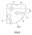
- the offset amount U of the vane groove 4 is represented by the distance between the center line L1 extending in the groove width direction and the linear line L2 extending in parallel with the center line L1 and passing through the axial line of the rotor R.
- aluminum or aluminum alloy As the material of the rotor R, aluminum or aluminum alloy is generally used.
- aluminum alloy consisting of Si: 14 to 16 mass%, Cu: 4 to 5 mass%, Mg: 0.45 to 0.65 mass%, Fe: 0.5 mass% or less, Mn: 0.1 mass% or less, Ti: 0.2 mass% or less, and the balance being Al and inevitable impurities can be exemplified.
- the production steps of the rotor in this embodiment mainly include a cutting step, a mass selection step, a forging step, a punching step, a heat treatment step, and an inspection step. Through these steps, a rotor product is shipped.
- the cutting step and the mass selection step are steps for obtaining a forging raw material.
- a continuously cast member is cut into a given length. After obtaining continuously cast members each having a predetermined length, each cast member is selected in accordance with the mass (weight) to obtain a desired forging raw material.
- the forging raw material is subjected to forge processing to obtain a rotor material. Thereafter, in the punching step, the excess thickness portions are removed form the rotor material to obtain a rotor.
- the rotor is subjected to a heat treatment and a quenching treatment to improve the hardness and the abrasion resistance to thereby obtain a rotor product.
- the inspection step the rotor product is subjected to a final inspection and then shipped when no defect is found.
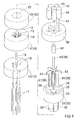
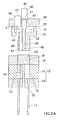
- Fig. 1 and Figs. 2A to 2D are views showing a forging die assembly as a forging device for use in forge processing of the first embodiment
- Fig. 3 is a view showing a rotor material 1 to be forged by the forging die assembly.
- the forging die assembly includes a lower die 10 and an upper die 30 for giving forming loads.
- the materials for these dies any well-known die steels can be used.
- the lower die 10 is divided into a lower die body 11 having a forming hole 12, a base 15 to be disposed at the lower side of the lower die body 11, and a bush 19 to be disposed at the upper side of the lower die body 11.
- the vane portion 13 is a thin plate-shaped member having one end circular in cross-section and has a cross-sectional shape corresponding to that of the vane groove 4.
- the base 15 is formed into a plate-shape, and has a center pin 16 for forming the center hole 3 of the rotor R fixed at the center of the base and through-holes 18 for knockout pins 17 surrounding the center pin 16.
- the bush 19 is an annular plate member provided with a loading hole 20 penetrated in the up-and-down direction and having the same diameter as that of the forming hole 12 of the lower die body 11.
- the center pin 16 is inserted into the forming hole 12 of the lower die body 11, forming the inner portion of the forming hole 12 into an inversion cross-sectional shape of the rotor R. Further, in this state, the loading hole 20 of the bush 19 communicates with the forming hole 12. Further, in the forging preparation step shown in Fig. 2A , the knockout pins 17 are inserted into the through-holes 18 of the base 15, and the tip end faces thereof are being held at the same height as the upper surface of the base 15.
- the upper die body 31 is divided into an upper die body 31 for applying a main load F to the forging raw material W, a cylindrical pin 40 for applying sub-loads F1 and F2, and flat plates 41.
- the lower-half punch portion 32 is formed into a generally cylindrical columnar member having an outer diameter corresponding to the through-hole 20 of the bush 19, and the larger-diameter upper half portion 33 is provided with a concave portion 34 at the upper surface thereof.
- a concave portion 34 Formed in this concaveportion 34 are a single circularhole 35 having a cross-section corresponding to the cross-section of the cylindrical pin 40 and configured to insert the cylindrical pin 40 in an advanceable and retractable manner and five flat holes 36 each having a cross-section corresponding to the cross-section of the flat plate 41 and configured to insert the flat plate 41 in an advanceable and retractable manner.
- the circular hole 35 and the flat holes 36 are penetrated up to the tip end face of the punch portion 32, respectively, and the flat holes 36 are opened to the outer peripheral surface of the punch portion 32.
- the position of the circular hole 35 and the positions of the flat holes 35 correspond to the position of the center pin 16 and the positions of the vane portions 13 of the lower die body 11, respectively.
- the cylindrical pin 40 is a cylindrical pin having a diameter larger than that of the center pin 16 in the lower die body 11, and is integrallyprovidedwith, at its upper end, a retaining portion 42 having a diameter larger than that of the circular hole 35.
- the flat plate 41 is a thin-plate member having a round portion at its tip end in the same manner as in the vane portion 13 of the lower die body 11, but the flat plate 41 is one size larger than the vane portion 13 and integrally provided with, at its upper end, a retaining portion 43 enlarged in cross-sectional area than the flat hole 36.
- the cylindrical pin 40 in a state in which the cylindrical pin 40 is fitted into the circular hole 35 from the concave portion 34 of the upper die body 31, and the flat plates 41 are fitted into the respective flat holes 36, the upper die body 31, the cylindrical pin 40, and the flat plates 41 form a single cylindrical columnar member having a continuous tip end face and a continuous peripheral surface.
- a gas cushion 45 for applying a load thereto is arranged above each of the cylindrical pin 40 and flat plates 41.
- a piston rod 47 is inserted into the cylinder 46 in an advanceable and retractable manner.
- the sealed compressed gas causes a force in the advancing direction equal to the force in the retracting direction.
- the cylinder 46 is fixed to the mounting board 48.
- the upper die body 31 and the mounting board 48 are assembled in a state in which the tip end of the piston rod 47 is in contact with the corresponding retaining portion 42 and 43 of the cylinder pin 40 and the flat plate 41 and an initial load by the advancing force of each pis ton rod 47 is applied to the corresponding cylindrical pin 40 and the flat plate 41.
- the cylindrical pin 40 and the flat plates 41 are moved upward to cause retraction movements of the piston rods thereof, a load corresponding to the retracted distance is applied to each of the cylindrical pin 40 and the flat plates 41. Therefore, the mounting board 48 is configured to move up and down together with the upper die 30, but the sub-loads F1 and F2 applied to the cylindrical pin 40 and the flat plate 41, respectively, are controlled by the gas cushions 45 independent from the main load F.
- the value of the first sub-load F1 and that of the second sub-load F2 can be adjusted by setting the operating load of the gas cushion 45. Furthermore, the cylindrical pin 40 and the flat plates 41 are each provided with the gas cushion 45, and therefore can be controlled in load independently. In other words, the main load F applied to the upper die body 32, the first sub-load F1 applied to the cylindrical pin 40 and the five second sub-loads F2 applied to the five flat plates 41 can be set independently.
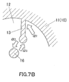
- the lower die body 10 and the upper die body 30 are arranged such that the cylindrical pin 40 and the flat plates 41 are arranged at the respective positions corresponding to the center pin 16 and the vane portions 13. Therefore, as shown in Figs. 7A and 7B , the first sub-load F1 is applied to directly above the center pin 16, and the second sub-load F2 is applied to directly above the vane portion 13.
- the main load F is applied to the portions other than the center pin 16 and the vane portions 13. Furthermore, in this invention, each of the first sub-load F1 and the second sub-load F2 is set to a value smaller than the main load F.
- lubricant agent is applied to required portions of the lower die 20 and the upper die 30, and a cylindrical forging raw material 49 is loaded in the loading hole 20 of the bush 19.
- the forging raw material W is a material produced by a method, such as, e.g., a method in which a continuous cast material is cut into a predetermined length, and heated to a predetermined temperature as needed.
- aqueous graphite lubricant agent and oil-graphite lubricant agent can be exemplified.
- the pre-heating temperature is preferably set to 400 to 450°C.
- the main load F is applied to the portions of the forging raw material W not corresponding to the cylindrical pin 40 and the flat plates 41, while the first sub-load F1 and the second sub-load F2 independent from the main load F are applied to the portions of the forging raw material W corresponding to the cylindrical pin 40 and the flat plates 41.
- the optimum value of the first sub-load F1 and that of the second sub-load F2 are appropriately set depending on the volume of the center pin 16 and that of the vane portion 13. As these volumes increase, the escape amount of material increases. Therefore, provided that the volume of the vane portion 13 is constant, the balance can be maintained by increasing the inflow amount into the circular hole 35 by decreasing the first sub-load F1 as the volume of the center pin 16 increases.
- first sub-load F1 and the second sub-road F2 are set to be smaller than the main load F, the materials pushed back by the cylindrical pin 16 and the vane portions 13 easily flow. This enables the upper die 30 to move downward to the height where the cylindrical pin 16 and the vane portions 13 break into the circular hole 35 and the flat holes 36, respectively.
- excess thickness portions 5 and 6 corresponding to the portions of the center hole 3 and the vane grooves 4 are formed on the upper end face (one end face 2a) of the rotor portion 2.
- the first sub-load F1 and the second sub-load F2 are applied separately. Therefore, the excess thickness portion 5 above the center hole 3 and the excess thickness portion 6 above the vane groove 4 are formed separately.
- the respective planner shapes of the excess thickness portions 5 and 6 become corresponding cross-sectional shapes of the cylindrical pin 40 and the flat plates 41.
- the rotor material 1 is constituted by the rotor portion 2 and the excess thickness portions 5 and 6, and the rotor portion 2 does not include the excess thickness portions 5 and 6.
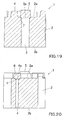
- the formed excess thickness portions 5 and 6 are, as shown in Figs. 10 and 11 , formed so that they protrude from one end face 2a of the rotor portion 2 toward the one end side and that the center hole 3 and the vane grooves 4 are formed up to the inside of each excess thickness portion 5 and 6.
- the center hole side excess thickness portion 5 includes a closing portion 5a closing one end face 3a of the center hole 3, and a peripheral wall portion 5b closing the peripheral side surface of the center hole 3, and is finished to have a generally reversed U-shape in cross-section.
- the vane groove side excess thickness portion 6 includes a closing portion 6a closing one end face 4a of the vane groove 4, and a peripheral wall portion 6b closing the peripheral side surface of the vane groove 4, and is finished to have a generally reversed U-shape in cross-section.
- the peripheral wall portions 5b and 6b of the excess thickness portion 5 are portions to be positioned within the range from one end face 2a of the rotor portion 2 to one end faces 3a and 4a of the center hole 3 and the vane groove 4.
- the closing portions 5a and 6a are portions to be positioned at the one end side outer than one end faces 3a and 4a of the center hole 3 and the vane groove 4.
- the main load F, the first and second sub-load F1 and f2 are adjusted so as to cause cracks 7 and 7 in the peripheral wall portions 5b and 6b of the excess thickness portions 5 and 6. These cracks 7 and 7 are formed to facilitate the removals of the excess thickness portions 5 and 6 during the punching step mentioned below.
- the excess thickness portions 5 and 6 are formed to have a specific structure to easily and accurately remove the excess thickness portions 5 and 6. The detail structures of the excess thickness portions 5 and 6 will be explained later.
- both the center hole 3 and the vane grooves 4 are opened.
- the main load F, the first sub-load F1, and the second sub-load F2 are appropriately set depending on the shape, the dimension of each portion, the material composition, the processing temperature, etc., of the rotor material 1.
- a first sub-load F1 and second sub-load F2: 29 to 89 MPa can be exemplified.
- first sub-load F1 and the second sub-load F2 are set too small, there is a possibility that the excess thickness portion 5 and 6 will be torn off. To the contrary, if they are set too large, the effects of reducing the force to be applied to the center pin 16 and the force to be applied to the vane portion 13 decrease.
- the first sub-load F1 and the second sub-load F2 so as to fall within the range of 29 to 89 MPa, more preferably 39 to 49 MPa, respectively.
- the first sub-load F1 and the second sub-load F2 increase as the upper die 30 goes downward.
- the load within the aforementioned preferable range is an initial load.
- the sub-load applying means for applying the first sub-load F1 and the second sub-load F2 are not specifically limited, but it is preferable to use a means which can apply a load in accordance with the raising and lowering operation of the upper die 30. From this aspect, a spring-type means such as a gas cushion is preferably used. As other sub-load applying means, a mechanical type spring, a hydraulic mechanism, and a shock absorber can be exemplified.
- the planner shape of each of the excess thickness portions 5 and 6 of the rotor 1 is preferably set to a shape in which an enlarged portion having a width "t": 0.1 to 3 mm is added to the periphery of each of the center pin 16 and the vane portion 13.
- the width "t" is less than 1 mm, the material flow during the forge processing deteriorates, causing breakages of the excess thickness portions 5 and 6, which in turn may cause deteriorated deformation preventing effects by breakages. If it exceeds 3 mm, there is a possibility that the circular hole 35 and the flat hole 36 in the upper die 30 interfere with each other.
- the most preferable gap "t" is 1 to 2 mm.
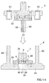
- Fig. 14 is a cross-sectional view schematically showing a punching device (die set) as an excess thickness portion removing device used in the punching step (excess thickness portion removing step).
- this punching device is equipped with a lower die 8 and an upper die 9, and configured to punch out the excess thickness portions 5 and 6 from the rotor material 1 by punching processing, as will be detailed below.
- the lower die 8 is equipped with a lower plate 81 and a lower die body 85 disposed on the upper surface of the lower plate 81.
- the lower plate 81 has, at its center portion, an excess thickness portion discharging hole 82 penetrated in the up-and-down direction. Further, at both side portions of the lower plate 81, guide bars 83 are formed so as to extend in the vertical direction.
- the lower die body 85 is fixed to the upper surface of the lower plate 81 so as to close the excess thickness discharging hole 82.
- the lower die body 85 is provided with a work mounting portion 86 corresponding to the excess thickness discharging hole 82 of the lower plate 81.
- the work mounting portion 86 is configured such that the rotor material 1 can be mounted with its one end face 2a facing downward.
- a center hole side punch-out hole 87 is formed corresponding to the center hole side excess thickness portion 5 and a vane groove side punch-out hole 88 is formed corresponding to the vane groove side excess thickness portion 6.
- This center hole side punch-out hole 87 is formed to have an inner peripheral shape corresponding to the outer peripheral shape of the center hole side excess thickness portion 5, so that the center hole side excess thickness portion 5 can be fitted therein in a closely fitted manner.
- the vane groove side punch-out holes 88 are formed to have an inner peripheral shape corresponding to the outer peripheral shape of the vane groove side excess thickness portion 6, so that the vane groove excess thickness portion 6 can be fitted therein in a closely fitted manner. Further, each punch-out hole 87 and 88 is penetrated in the up-and-down direction, and the lower end side thereof is communicated with the excess thickness discharging hole 82 of the lower plate 81.
- the rotor material 1 can be set on the work mounting portion 86 in a positioned state by fitting the excess thickness portions 5 and 6 of the rotor material 1 in the punch-out holes 87 and 88 in a closely fittedmanner, respectively, and disposing one end face 2a of the rotor portion 2 on the work mounting portion 86.
- the upper die 9 is equipped with an upper plate 91 and an upper die body 95 disposed on the lower surface of the upper plate 91.
- the upper plate 91 is configured to move upward and downward in the vertical direction by being driven upward and downward by a lifting and lowering driving means such as a hydraulic cylinder (not illustrated).
- a lifting and lowering driving means such as a hydraulic cylinder (not illustrated).
- guide holes 93 are formed corresponding to the guide bars 83 of the lower plate 81. As will be described later, when the upper plate 91 is moved downward, the guide bars 83 are inserted in the guide holes 93 to guide the descending movement of the upper plate 91.
- the upper die body 95 is fixed to the lower surface of the upper plate 91 so as to face the lower die body 85.
- a center hole side blanking punch 97 and vane groove side blanking punches 98 are attached to the upper die body 95 in a downwardly protruded manner, corresponding to the center hole side punch-out hole 87 and the vane groove side punch-out holes 88, respectively, i.e., corresponding to the center hole 3 and vane grooves 4 of the rotor material 1 set to the lower die 85.
- the blanking punches 97 and 98 are structured as an impactor.
- the rotor material 1 is mounted on the work mounting portion 86 of the lower die 8 of the punching device with the one end face 2a facing downward in a state in which each excess thickness portion 5 and 6 is fitted in the corresponding punch-out hole 87 and 88.
- the center hole side blanking punch 97 and vane groove side blanking punch 98 of the upper die body 85 are arranged so as to face the other end side openings of the center hole 3 and vane grooves 4 of the rotor material 1.
- the excess thickness portions 5 and 6 are formed on one end face 2a of the rotor portion 2 so as to protrude from one end side. Therefore, when the excess thickness portions 5 and 6 are punched out, the excess thickness portions 5 and 6 can be accurately broken at the positions of the peripheral wall portions 5a and 6a, thereby enabling accurate removals of the excess thickness portions 5 and 6 with high dimensional accuracy.
- the crack 7 and 7 is formed at the breakage scheduled portion, and therefore the punching load of the punch 97 can be concentrated at the position of the crack 7, resulting in assured breakage at the position.
- the excess thickness portion 5 and 6 can be punched out assuredly.
- the press working can be performed at a low load, it is possible to effectively prevent occurrence of harmful cracks and/or breakage in the rotor R, which in turn can produce a high quality rotor product.
- the punch load can be reduced into about 1/2 as compared with the case in which no crack is formed.
- the excess thickness portions 5 and 6 are partially formed at the vicinities of the center hole 3 and the vane groove 4 in the end face of the rotor material 1 by the forge processing, and it is configured to remove only the partial excess thickness portions 5 and 6. Therefore, the capacity of the excess thickness portions 5 and 6, or the excessive material, can be reduced, enabling improvement of the material yield ratio, which in turn can reduce the cost.
- the punching processing is performed as cold working since it is not especially required to heat the rotor material 1.
- the punching processing can be performed as hot processing by heating the rotor material 1 immediately before performing the punching processing.
- burrs 5c 6c are removed as the need arises.
- it can be configured to provide a burr removing step between the punching step and the heat treatment step to remove the burrs 5c and 6c or to provide a burr removing step between the heat treatment step and the inspection step.
- burrs 5c and 6c can be removed by the finish cutting work. Therefore, it is not required to dare to remove the burrs 5c and 6c during the production step of the rotor R.
- the breaking section at the time of removing the excess thickness portion 5 and 6 can be positioned at the same position as one end 2a of the rotor portion 2 or at the position inner than the one end 2a to prevent occurring the burrs 5c and 6c.
- the exemplified rotor R to be manufactured is set to 30 to 60 mm in axial direction length; 45 to 65 mm in outer diameter (diameter); 10 to 15 mm in diameter of the center hole 3; 2 to 4 mm in the width of the vane groove 4; and 15 to 20 mm in the depth of the vane groove 4 from the outer peripheral surface.
- the thickness of the center hole side closing portion 5a i.e., the dimension from the tip end of the excess thickness portion 5 to one end face 3a of the center hole 3
- the height of the peripheral wall portion 5b i.e., the dimension from one end face 5a of the center hole 5 to one end face 2a
- the protruded amount H5 of the excess thickness portion 5 becomes equal to "T5+Z5.”
- the center hole side excess thickness portion 5 is preferably set to: 3.5 to 12 mm in the protruded amount H5 of the excess thickness portion 5; 3 to 10 mm in the thickness T5 of the closing portion 5a; and 0.5 to 2 mm in the height T5 of the peripheral wall portion 5b.
- the closing portion thickness T5 is too small, the breaking position at the time of removing the excess thickness portion 5 becomes unstable, resulting in short die life and deteriorated dimensional accuracy.
- the closing portion thickness T5 is too large, the material yielding rate deteriorates.
- the draft angle ⁇ 5 of the excess thickness portion 5 is set to 0 to 10° and that the curvature radius r5 of the raising portion (basal portion) in the outer peripheral surface of the excess thickness portion 5 is set to 0.5 to 3 mm.
- the protruded amount H6 of the excess thickness portion 6 becomes equal to the value obtained by adding the height Z5 of the peripheral wall portion 6b to the thickness T6 of the closing portion 6a.
- the most preferable structure of the vane groove side excess thickness portion 6 is the same as mentioned above. That is, for the same reasons as mentioned above, it is preferable that the protruded amount H6 of the excess thickness portion 6 is set to 3.5 to 12 mm, the thickness T6 of the closing portion 6a is set to 3 to 10 mm, and the height Z6 of the peripheral wall portion 6b is set to 0.5 to 2 mm. Furthermore, in the same manner as mentioned above, it is preferable that the draft angle ⁇ 6 of the excess thickness portion 6 is set to 0 to 10° and that the curvature radius r6 of the raising portion (basal portion) in the outer peripheral surface of the excess thickness portion 6 is set to 0.5 to 3 mm.
- the excess thickness portions 5 and 6 can be accurately punched out with punches 97 and 98.
- the adjustments of the curvature radii r5 and r6 are important. That is, if the curvature radius r5 and r6 is decreased, cracks will be generated easily, which can enlarge the cracks. To the contrary, if the curvature radii r5 and r6 are increased, cracks 7 will be hardly generated, resulting in small cracks 7. Accordingly, by adjusting the curvature radius r5 and r6, the size, shape, position, etc., of the crack can be controlled appropriately, which enables assured removals of the excess thickness portions 5 and 6 with higher dimensional accuracy.
- the excess thickness portions 5 and 6 are removed by punching operation, as compared with the case in which the excess thickness portions are removed by machining process, such as, cutting work, which is poor in efficiency, the excess thickness portions 5 and 6 can be removed more efficiently, which in turn can improve the product efficiency.
- the excess thickness portions 5 and 6 are formed so as to protrude from one end face 2a of the rotor material 1, the excess thickness portions 5 and 6 can be easily removed with high dimensional accuracy by punching operation.
- the rotor R in which the excess thickness portions 5 and 6 have been removed at the punching step will be shipped through the heat treatment step and the inspection step after removal of the burrs 5c and 6c as need arises as mentioned above (see Fig. 9 ).
- each of the excess thickness portions 5 and 6 was structured by a protruded portion protruded from one end face 2a of the rotor portion 2 and each of the center hole 3 and the vane groove 4 was formed up to the position located at the outside of the one end face 2a in each of the excess thickness portions 5 and 6.
- each one end face 3a and 4a of the center hole 3 and the vane groove 4 is formed so as to be located at approximately the same position as one end face 2a of the rotor portion 2.
- the center hole 3 and the vane groove 4 can be formed such that each of one end faces 3a and 4a is positioned inner than one end face 2a of the rotor portion 2.
- cracks 7 and 7 are formed from the raising position of the outer peripheral surface of each of the excess thickness portion 5 and 6 to the end corner position of each of the center hole 3 and the vane groove 4, and each of the excess thickness portions 5 and 6 is broken at the position and removed. Therefore, at the removed positions of the excess thickness portions 5 and 6, chamfered cutout portions are formed at the center hole peripheral edge portion and the vane groove peripheral edge portion of one end face 2a of the rotor material 1. This assuredly prevents forming of burrs.
- the excess thickness portions 5 and 6 are punched out by the punches 97 and 98 inserted from the other end side of the center hole 3 and vane grooves 4.
- the removal processing of the excess thickness portions is not limited to the blanking processing by a punch.
- it can be configured such that an impact member such as a hammer is hit against the excess thickness portions from the outside of the rotor material 1, for example, in a direction perpendicular to the axis direction to remove the excess thickness portion by the impacts, or the basal ends (base end portions) of the excess thickness portions 5 and 6 are cut (sheared) along the plane perpendicular to the axial direction using an impact member such as a cutting tool.
- an impact member such as a hammer is hit against the excess thickness portions from the outside of the rotor material 1, for example, in a direction perpendicular to the axis direction to remove the excess thickness portion by the impacts, or the basal ends (base end portions) of the excess thickness portions 5 and 6 are cut (sheared) along the plane perpendicular to the axial direction using an impact member such as a cutting tool.
- the center pin 16 and vane groove forming vane portions 13 are formed in the lower die 10 and that the center hole 3 is formed simultaneously with the forming of the vane grooves 4.
- the forming method of the center hole is not limited to the above.
- it can be configured such that the center hole is formed in the forming raw material in advance before per forming the forge processing, or that only vane grooves are formed by forge processing using a die assembly with no center pin and then the center hole is formed in the rotor material with vane grooves at the post-processing.
- the forge processing and the excess thickness portion blanking processing are performed using separate devices.
- the forge processing and the excess thickness portion blanking processing can be performed with the same device.
- the vane portions 13 and the center pin 16 of the lower die 10 For example, in the forging device shown in Figs. 1 and 2 , as the vane portions 13 and the center pin 16 of the lower die 10, longer ones are used.
- the upper die 30 is moved downward at approximately the same stroke amount as in the aforementioned embodiment to thereby perform the same forge processing.
- the upper die 30 is subsequently moved downward at the stroke amount larger than in the forge processing to thereby punch out the excess thickness portions 5 and 6 by the vane portions 13 and the center pin 16.
- a forging device of the type in which the vane groove forming vane portions 13 and the center hole forming pin 16 are arranged in the fixed side die such as the lower die 10 is used.
- the present invention is not limited to it, and allows the use of a forging device of the type in which the vane groove forming vane portions (punches) and the center hole forming pin (punch) are arranged in the movable side die such as the upper die 30.
- the forging processing and the excess thickness portion blanking processing can be performed with a. single device (forging device).
- Figs. 21 to 26 show a rotor material 1 to be obtained by forge processing according to a second embodiment of the present invention.
- the rotor material 1 is constituted by a rotor portion 2 and excess thickness portions 5 and 6.
- the rotor portion 2 does not include the excess thickness portions 5 and 6.
- the excess thickness portions 5 and 6 are formed so as to protrude toward one end side from one end face 2a to the rotor portion 2.
- one end face 3a of the center hole 3 does not reach the inside of the excess thickness portion 5, and the one end face 3a is disposed inner than the one end face 2a of the rotor 2.
- one end face 4a of the vane groove 4 also does not reach the inside of the excess thickness portion 6, and the one end face 4a is disposed inner than the one end face 2a of the rotor 2.
- both the center hole 3 and the vane grooves 4 are opened.
- the end face difference (breaking length D3) between one end face 2a of the rotor portion 2 and one end face 3a of the center hole 3 is set to 0 to 2 mm
- the end face difference (breaking length D4) between one end face 2a of the rotor portion 2 and one end face 4a of the vane groove 4 is also set to 0 to 2 mm.
- the radius difference D5 between the outer peripheral surface of the excess thickness portion 5 and the inner peripheral surface of the center hole 3 is set to 0.01 to 0.1 mm, preferably 0. 05 to 0.1 mm.
- the radius difference D6 between the outer peripheral surface of the excess thickness portion 6 and the inner peripheral surface of the vane groove 4 is also set to 0.01 to 0.1 mm, preferably 0.05 to 0.1 mm.
- the radius difference D61 at the rotor portion outer peripheral side end portion and the radius difference D62 at the rotor portion inner peripheral side end portion are formed to be thicker than the radius difference D60 at the intermediate main portion.
- the curvature radius r3 between the inner periphery of the center hole 3 of the rotor material 1 and one end face 3a of the center hole 3 is set to 0.2 to 1 mm. Further, it is preferable that the curvature radius r4 between the inner periphery of the vane groove 4 and one end face 4a thereof is also set to 0.2 to 1 mm.
- the height B1 of the inner burr can be set to 1 mm or less. In cases where the height B1 of the inner burr exceeds 1 mm, the breaking position becomes unstable, resulting in difficult accuracy control of the inner side dimension of the center hole 3 and that of the vane groove 4.
- the curvature radius r3a (r4a) between the excess thickness portion 5 (6) of the rotor material 1 and one end fade 2a of the rotor material 1 is set to be equal to or less than the inner periphery side curvature radius r3 (r4) of the excess thickness portion 5 (6).
- the protruded burr height B2 can be set to 1 mm or less. Further, the breaking position can also be stabilized, resulting in smaller variation of the protruded burr height B2, which makes it easy to control the cut portion control at the post-processing and therefore makes it easy to control the dimensional accuracy of the center hole 3 and the vane groove 4. in cases where the height B2 of the inner burr exceeds 1 mm, the breaking position becomes unstable, which makes it difficult to control the accuracy of the inner size of the center hole 3 and the vane groove 4.
- the die used in the present invention is a die for forming a rotor material having the aforementioned shape in which the curvature radius r3a is formed at the circular hole 35 of the upper die, an inversion shape of the curvature radius r4a is formed at the flat hole 36, an inversion shape of the curvature radius r3 is formed at the center pin 16 of the lower die, and an inversion shape of the curvature radius r4 is formed at the vane portion 13.
- the rotor material 1 having the aforementioned structure is produced using the same forging device as in the first embodiment.
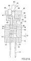
- a forging raw material 49 is mounted in the mounting hole 20 of the lower die 20 (see Fig. 2A showing the first embodiment). From this state, as shown in Fig. 27A , the upper die 30 is moved downward. Thus, when the upper die 30 has moved down to the bottom dead point, it is formed into a shape of the rotor material 1 as shown in Fig. 27B .
- the upper die 30 in a state in which the upper die 30 has reached the bottom dead point (in the die mated state), it is configured such that the level of the tip end face (upper end face) of the center pin 16 coincides with or distances from the level of the opening face (lower end face) of the circular hole 35.
- the one end face 3a of the center hole 3 in the rotor material 1 does not reach the inside of the excess thickness portion 5 and is positioned inner than the one end face 2a of the rotor portion 2, and that the one end face 4a of the vane groove 4 does not reach the inside of the excess thickness portion 6 and is positioned inner than the one end face 2a of the rotor portion 2.
- the distance (end face difference D3) between the tip end face of the center pin 16 and the opening face of the circular hole 35 is equal to the aforementioned center hole side breaking length D3 and set to 0 to 2 mm
- the distance (end face difference D4) between the tip end face of the vane portion 13 and the opening face of the flat hole 36 is equal to the aforementioned vane groove side breaking length and set to 0 to 2 mm (see Figs. 25 and 26 ).
- the clearance (diameter difference D5) between the outer periphery of the center pin 16 and the inner periphery of the circular hole 35 is equal to the radius difference D5 between the inner peripheral surface of the center hole 3 and the inner peripheral surface of the excess thickness portion 5 in the aforementioned rotor material 1, and set to 0.01 to 0.1 mm, preferably 0.05 to 0.1 mm
- the clearance (diameter difference D6) between the outer peripheral surface of the vane portion 13 and the outer peripheral surface of the flat hole 36 is equal to the diameter difference D6 between the inner periphery of the flat hole 36 and the inner periphery of the excess thickness portion 5 of the rotor material 1 and set to 0.01 to 0.1 mm, preferably 0.05 to 0.1 mm (see Figs. 25 and 26 ).
- the excess thickness portions 5 and 6 cannot be removed with a high degree of accuracy, which may cause adverse affects by the broken remains. To the contrary, if the radius differences D5 and D6 are too small, before the punching processing, the excess thickness portions 5 and 6 may drop improperly.
- the excess thickness portions 5 and 6 are removed using the punching device shown in Fig. 14 to produce a rotor R.
- the excess thickness portions 5 and 6 can be correctly removed at predetermined positions with high dimensional accuracy.
- the breaking length D3 and D4 of the excess thickness portions 5 and 6 are set to be small, the breaking area at the time of removing the excess thickness potions can be reduced and the removal operation can be performed easily with a low load, which can improve the production efficiency.
- the excess thickness portions 5 and 6 can be punched out by punches 97 and 98 with a low load. This effectively prevents occurring of harmful cracks and/or breakages in the rotor R due to a high load, and therefore a high quality rotor product can be produced.
- the processing can be performed with a low load, and therefore the abrasion of the punches 97 and 98 themselves can also be reduced, which can improve the durability of the punches 97 and 98. This in turn can further improve the durability of the punching device.
- the fracture remain (broken section) also becomes small.
- the adverse effects by the fracture remain can be avoided. Therefore, for example, it is not required to perform finish processing for finishing the fracture remain at the post-step, resulting in reduced steps, which can further improve the productivity and reduce the production cost.
- one ends 3a and 4a of the center hole 3 and the vane grooves 4 are positioned inner than one end face 2a of the rotor portion 2, and therefore the fraction remains after the removals of the excess thickness portions are positioned at the inner peripheries of the center hole 3 and vane groove 4 or at the inside of the rotor R. Also in this regard, adverse effects by the fracture remains can be prevented, assuredly making the post-finishing processing for the fracture remains unnecessary, which can further improve the productivity.
- the radius difference D61 at the rotor portion outer peripheral side end portion and the radius difference D62 at the rotor portion inner peripheral side end portion are formed to be thicker than the radius difference D60 at the intermediate main portion. Therefore, after the forge processing but before the punching processing, improper dropping of the excess thickness portion 6 can be prevented. For example, such a problem that the excess thickness portion 6 remains in the forge processing die can be prevented assuredly, which can maintain the high productivity.
- both endportions of the excess thickness portion 6 are formed to have large radius differences D61 and D62, improper breakage of these portions can be prevented assuredly, which can more assuredly prevent improper dropping of the excess thickness portion 6.
- both end portions of the excess thickness portion 6 often become breakage starting points at the time of dropping. Therefore, by forming both end portions to be thick, it becomes hard to cause the breakage, which prevents improper dropping more assuredly.
- the radius difference (D6) of the outer periphery of the excess thickness portion 6 at the side of the vane groove 4 is partially increased.
- the present invention is not limited to the above, and allows partially increasing the radius difference D5 of the outer periphery of the excess thickness portion 5 at the side of the center hole 3.
- a rotor material 1 shown in Fig. 3 was forged using a forging dies 10 and 30 shown in Figs. 1 and 2 .
- the rotor material 1 was a material for producing an aluminum alloy rotor R shown in Fig. 4 .
- the rotor R had an outer diameter: 52 mm, a height: 50 mm, a diameter of the center hole 3:10 mm, the number of vane grooves 4: 5, a groove width: 3 mm, a groove depth: 15 mm, an offset dimension U: 10 mm.
- the material alloy was A390 aluminum alloy.
- the clearance D5 between the center pin 16 of the lower die 10 and the circular hole 35 of the upper die 35 was set to 0.1 mm
- the clearance D6 between the vane portion 13 of the lower die 10 and the flat hole 36 of the upper die 30 was also set to 0.1 mm in the same manner as mentioned above.
- the distance (breaking length D3) between the center pin 16 of the lower die 10 and the opening face of the circular hole 35 of the upper die 30 was set to 1.5 mm
- the distance (breaking length D4) between the vane portion 13 of the lower die 10 and the opening face of the flat hole 36 of the upper die 30 was also set to 1.5 mm in the same manner as mentioned above.
- a forging raw material Wheated to 400 °C was mounted in the lower die 10 and formed into a rotor material 1 by applying the following forming loads. During this forging, the first sub-load F1 and the second sub-load F2 increased. Each of the final loads was 1.5 times of each initial load.
- the material yielding percentage of the rotor R with respect to the forging raw material W was 82.9 %.
- a rotor R was produced in the same manner as in the aforementioned Example 1 except that the breaking lengths D3 and D4 of the excess thickness portions 5 and 6 were set to "0 (zero)," respectively.
- a rotor R was produced in the same manner as in the aforementioned Example except that the breaking lengths D3 and D4 of the excess thickness portions 5 and 6 were set to "-2 mm,” respectively.
- a rotor R was produced in the same manner as in the aforementioned Example except that the breaking lengths D3 and D4 of the excess thickness portions 5 and 6 were set to "-2 mm,” respectively, and that the clearances D5 and D6 of the outer periphery of the excess thickness portions 5 and 6 were set to "2 mm,” respectively.
- Rotors R were produced in the same conditions as in the aforementioned Example 1 except that the curvature radiuses r3 and r3a of the center hole 3 were adjusted to the values as shown in Table 2. Then, the inner burrs and protruded burrs (see Fig. 26 ) were evaluated. The results are also shown in Table 2.
- the rotor production method according to the present invention can be applied in producing a rotor for use in, e.g., a compressor.
Landscapes
- Engineering & Computer Science (AREA)
- Mechanical Engineering (AREA)
- General Engineering & Computer Science (AREA)
- Rotary Pumps (AREA)
- Forging (AREA)
Abstract
Description
- The present invention relates to a rotor production method for producing a rotor having vane grooves at its outer peripheral portion, and its related technology.
- A rotor for a compressor or a rotor for a rotary type vacuum pump for use in a brake controller is generally provided with a plurality of vane grooves parallel to an axial center formed in an outer peripheral portion at equal intervals in the circumferential direction. Further, most of rotors for an air-conditioning rotary compressor and for a rotary vacuum pump for use in a brake controller, which are to be mounted on a vehicle, are aluminum alloy products for the purpose of attaining the weight saving, and generally produced by forge processing.
- For example, according to the rotor production method disclosed by the following
Patent Document 1, using a lower die having a forming hole in which vane portions for forming vane grooves are formed, a cylindrical columnar forging raw material set on the forming hole is downwardly pressed with an upper die to thereby fill the forging raw material in the forming hole. With this, a cylindrical columnar rotor material inwhich each vane groove extends from the lower end face near to the upper end face is formed can be obtained. The upper end portion (excess thickness portion) of the rotor material is removed by cutting along a plane perpendicular to the axial line to open one end side (upper end side) of each vane groove, resulting in vane grooves with both ends thereof opened. Thus, a rotor material is formed. - Further, according to the rotor production method disclosed by the following
Patent Document 2, using an upper die provided with groove forming punches for forming vane grooves at the forming surface of the upper die, the upper die with the groove forming punches are driven into a forging raw material set in the forming hole of the lower die, to thereby form vane grooves extending from the upper end face near to the lower end face. Subsequently thereafter, a groove forming punch is driven therein to punch out and remove the excess thickness portion closing the lower end side of the vane groove to open both ends of the vane groove. -
- Patent Document 1: Japanese Unexamined Laid-open Patent Publication No.
H11-230068 JP H11-230068, A - Patent Document 2 : Japanese Unexamined Laid-open Patent Publication No.
2000-220588 JP 2000-220588, A - In the conventional rotor producing method disclosed by the
aforementioned Patent Document 1, the excess thickness portions of the rotor material obtained by forge processing are removed. The machining process such as cutting work is, however, poor in production efficiency. Therefore, as long as such machining process low in production efficiency is used, it is difficult to perform to improve the overall production efficiency. - Further, in the conventional rotor production method disclosed by the
aforementioned Patent Document 2, the excess thickness portion blocking the lower end portion of the vane groove is punched out and removed with a groove formingpunch. It is, however, difficult to accurately control the breakingposition in the punching operation, and therefore there is a high probability of causing unexpected breaks or lacks. Accordingly, there is a problem that the excess thickness portion cannot be removed accurately. - The preferred embodiments of the present invention have been developed in view of the above-mentioned and/or other problems in the related art. The preferred embodiments of the present invention can significantly improve upon existing methods and/or apparatuses.
- The present invention was made in view of the aforementioned problems, and aims to provide a rotor production method capable of accurately removing an excess thickness portion while securing high production efficiency and its related technology.
- Other objects and advantages of the present invention will be apparent from the following preferred embodiments.
- In order to attain the aforementioned objects, the present invention is provided with the following structures.
- [1] A production method of a rotor, the method comprising:
- a forging step for obtaining a rotor material having a cylindrical columnar rotor portion in which a plurality of vane grooves extending along an axial direction are formed in an outer peripheral portion at intervals in a circumferential direction and an excess thickness portion integrally formed on one end face of the rotor portion so as to protrude toward one end side of the rotor portion and close one end side of the vane groove; and
- an excess thickness portion removing step for obtaining a rotor having the vane grooves opened at the one end side by hitting the excess thickness portion with an impact applying member to thereby remove the excess thickness portion from the rotor portion.
- [2] The production method of a rotor as recited in the
aforementioned Item 1, wherein, in the rotor material, the excess thickness portion is formed so as to protrude toward the one end side of the rotor portion beyond the one end face and the vane groove is formed so as to reach an inside of the excess thickness portion. - [3] The production method of a rotor as recited in the
aforementioned Item 2, wherein the excess thickness portion has a peripheral wall portion closing a peripheral side surface of the vane groove, and wherein, at the excess thickness portion removing step, the excess thickness portion is broken at the peripheral wall portion and removed. - [4] The production method of a rotor as recited in the
aforementioned Item - [5] The production method of a rotor as recited in any one of the
aforementioned Items 1 to 4, wherein, at the forging step, a crack is formed between the excess thickness portion and the rotor portion, and wherein, at the excess thickness portion removing step, the rotor material is broken along the crack. - [6] The production method of a rotor as recited in any one of the
aforementioned Items 1 to 5, wherein, at the excess thickness portion removing step, a blanking punch as an impactor is driven into the vane groove of the rotor material from the other end side opening to thereby punch out and remove the excess thickness portion toward the one end side. - [7] The production method of a rotor as recited in any one of the
aforementioned Items 1 to 6,
wherein, at the forging step, a vane groove forming die is relatively driven into a cylindrical columnar forging raw material from the other end face thereof to thereby form the vane groove extending from the other end face to the one end face, and
wherein, when the vane groove forming die is driven into the forging raw material, a back-pressure is applied to an area corresponding to the vane groove forming scheduled portion on the one end face of the forging raw material. - [8] The production method of a rotor as recited in any one of the
aforementioned Items 1 to 7,
wherein, when the excess thickness portion is defined as a vane groove side excess thickness portion and the impact applying member is defined as a vane groove side impact applying member,
wherein, at the forging processing, a shaft hole is formed in the rotor portion of the rotor material so as to extend in the axial direction, and a shaft hole side excess thickness portion closing the one end side of the shaft hole is integrally formed on the one end face of the rotor portion so as to protrude toward the one end side, and
wherein, at the excess thickness portion removing step, the shaft hole side impact applying member is hit against the shaft hole side excess thickness portion to remove the excess thickness portion from the rotor portion so that the shaft hole is opened at the one end side. - [9] The production method of a rotor as recited in the
aforementioned Item 8, wherein a blankingpunch as the impact applying member is driven into the shaft hole of the rotor material from the other end side opening to punch out and remove the shaft hole side excess thickness portion toward the one end side. - [10] The production method of a rotor as recited in the
aforementioned Item
wherein, at the forging step, a shaft hole forming die is relatively driven into a cylindrical columnar forging raw material from the other end face thereof to thereby form the shaft hole extending from the other end face to the one end face, and
wherein, when the shaft hole forming die is driven into the forging raw material, a back-pressure is applied to an area corresponding to the shaft hole forming scheduled portion on the one end face of the forging raw material. - [11] The production method of a rotor as recited in the
aforementioned Item 1,
wherein, in the rotor material, the excess thickness portion is integrally formed on the one end face of the rotor portion so as to protrude toward the one end side, and
wherein one end face of the vane groove does not reach the excess thickness portion and is positioned inner than the one end face of the rotor portion. - [12] The production method of a rotor as recited in the
aforementioned Item 11, wherein, when a distance between the one end face of the rotor portion and the one end face of the vane groove in the rotor material is defined as an end face difference, the end face difference at the vane groove side is set to 0 to 2 mm. - [13] The production method of a rotor as recited in the
aforementioned Item - [14] The production method of a rotor as recited in any one of the
aforementioned Items 11 to 13, wherein the vane groove side radius difference partially differs. - [15] The production method of a rotor as recited in the
aforementioned Item 13 or 14, wherein among the vane groove side radius differences, at least one of the radius difference at an inner peripheral side end portion of the vane groove and the radius difference at the outer peripheral side end portion of the vane groove is set to be larger than a radius difference at an intermediate portion of the vane groove. - [16] The production method of a rotor as recited in any one of the
aforementioned Items 11 to 15,
wherein, when the excess thickness portion is defined as a vane groove side excess thickness portion and the impact applying member is defined as a vane groove side impact applying member,
wherein, at the forging processing, a shaft hole is formed in the rotor portion of the rotor material so as to extend in the axial direction, and a shaft hole side excess thickness portion closing the one end side of the shaft hole is integrally formed on the one end face of the rotor portion so as to protrude toward the one end side,
wherein, at the excess thickness portion removing step, the shaft hole side impact applying member is hit against the shaft hole side excess thickness portion to remove the excess thickness portion from the rotor portion so that the shaft hole is opened at the one end side, and
wherein, in the rotor material produced by the forging processing, one end face of the shaft hole does not reach the shaft hole side excess thickness portion and is positioned inner than the one end face of the rotor portion. - [17] The production method of a rotor as recited in the
aforementioned Item 16, wherein, when a distance between the one end face of the rotor portion and the one end face of the shaft hole in the rotor material is defined as a shaft hole side end face difference, the shaft hole side end face difference is set to 0 to 2 mm. - [18] The production method of a rotor as recited in the
aforementioned Item - [19] The production method of a rotor as recited in any one of the
aforementioned Items 16 to 18, wherein the shaft hole side radius difference partially differs. - [20] A method of removing an excess thickness portion of a rotor material having a cylindrical columnar rotor portion in which a plurality of vane grooves extending along an axial direction are formed in an outer peripheral portion at intervals in a circumferential direction and the excess thickness portion integrally formed on one end face of the rotor portion so as to protrude toward one end side of the rotor portion and close one end side of the vane groove,
wherein an impact applying member is hit against the excess thickness portion to remove the excess thickness portion from the rotor portion to thereby open the vane groove at the one end side. - [21] A device for removing an excess thickness portion of a rotor material having a cylindrical columnar rotor portion in which a plurality of vane grooves extending along an axial direction are formed in an outer peripheral portion at intervals in a circumferential direction and the excess thickness portion integrally formed on one end face of the rotor portion so as to protrude toward one end side of the rotor portion and close one end side of the vane groove,
wherein the device is provided with a blanking punch configured to drive into the vane groove of the rotor material from the other end side opening of the vane groove and hit against the excess thickness portion to punch out and remove the excess thickness portion from the rotor portion to thereby open the vane groove at the one end side. - In the present invention, it is possible to replace the structures corresponding to the vane groove in the aforementioned items [2] - [7] with those corresponding to the shaft hole to limit to the structures of the aforementioned items [8], [20] and [21].
- Further, it is possible to limit the structures of aforementioned items [20] and [21] with the structures of the aforementioned items [11] - [19].
- According to the rotorproductionmethodof the invention [1], since the excess thickness portions are removed by hitting them with an impact applying member, high production efficiency can be secured. Further, since the excess thickness portion is protruded, hitting by the impact applying member enables assured removal of the excess thickness portions.
- According to the rotor production method of the invention [2] to [6], the aforementioned effects can be obtainedmore assuredly.
- According to the rotorproductionmethod of the invention [7], the excess thickness portions structured as mentioned above can be formed assuredly.
- According to the rotor product ion method of the invention [9], the shaft side excess thickness portion can be removed more assuredly.
- According to the rotor production method of the invention [10], in the same manner as mentioned above, the excess thickness portions can be removed accurately while maintaining the high production efficiency.
- According to therotorproductionmethodof the invention [11], since the radius difference between the vane groove inner peripheral surface and the excess thickness portion outer peripheral surface can be reduced, the vane groove side excess thickness portions can be removed simply and accurately, which can improve the production efficiency.
- According to the rotor production method of the invention [12] and [13], the aforementioned effects can be obtained assuredly.
- According to the rotor product ion method of the invention [14] to [15], it is possible to prevent improper dropping of the excess thickness portions.
- According to the rotorproductionmethodof the invention [16], since the radius difference between the shaft hole inner peripheral surface and the excess thickness portion outer peripheral surface can be reduced, the shaft hole side excess thickness portion can be removed simply and accurately, which can further improve the production efficiency.
- According to the rotorproductionmethodof the invention [17] and [18], the shaft side excess thickness portion can be removed more assuredly.
- According to the rotor production method of the invention [19], it is possible to prevent improper dropping of the shaft side excess thickness portion.
- According to the rotor material excess thickness portion removing method of the invention [20], the shaft hole side excess thickness portion can be removed accurately and efficiently.
- According to the rotor material excess thickness portion removing device of the invention [21], in the same manner as mentioned above, the excess thickness portions can be removed accurately while maintaining the high production efficiency.
-
- [
Fig. 1] Fig. 1 is an exploded perspective view showing a rotor material forging die assembly used in forge processing of a rotor producing method according to a first embodiment of the present invention. - [
Fig. 2A] Fig. 2A is a schematic cross-sectional view showing the forge processing at the stage of preparing the forge processing using the forging die assembly according to the first embodiment. - [
Fig. 2B] Fig. 2B is a schematic cross-sectional view showing the forge processing at the stage of descending the upper die using the forging die assembly according to the first embodiment. - [
Fig. 2C] Fig. 2C is a schematic cross-sectional view showing the forge processing at the processing completion stage using the forging die assembly according to the first embodiment. - [
Fig. 2D] Fig. 2D is a schematic cross-sectional view showing the forge processing at the stage of taking out the processed member using the forging die assembly according to the first embodiment. - [
Fig. 3] Fig. 3 a perspective view showing a rotor material obtained by the forge processing according to the first embodiment. - [
Fig. 4] Fig. 4 is a perspective view showing a rotor to be produced by the production method of the first embodiment. - [
Fig. 5] Fig. 5 is a plan view showing the offset amount of the vane groove of the rotor material shown inFig. 4 . - [
Fig. 6] Fig. 6 is a perspective view showing the assembled state of the upper die of the forging die assembly of the first embodiment. - [
Fig. 7A] Fig. 7A is a partially cut-out perspective view showing the load applying state to the lower die of the forging die assembly. - [
Fig. 7B] Fig. 7B is an explanatory view for explaining the metal flow in the forming die assembly during the forge processing. - [
Fig. 8] Fig. 8 is a plan view of the rotor material according to the first embodiment. - [
Fig. 9] Fig. 9 is a flowchart showing the step sequence of the production method in the first embodiment. - [
Fig. 10] Fig. 10 is a cross-sectional view showing the rotor material cut along the center hole according to the first embodiment. - [
Fig. 11] Fig. 11 is a cross-sectional view showing the rotor material cut along the vane groove according to the first embodiment. - [
Fig. 12] Fig. 12 is an enlarged cross-sectional view showing the portion surrounded by the alternate long and two short dashes line shown inFig. 10 . - [
Fig. 13] Fig. 13 is an enlarged cross-sectional view showing the portion surrounded by the alternate long and two short dashes line shown inFig. 11 . - [
Fig. 14] Fig. 14 is a schematic cross-sectional view of a punching device used at the excess thickness portion removing step in the production method according to the first embodiment. - [
Fig. 15] Fig. 15 is an enlarged cross-sectional view showing the vicinity of the center hole portion of the rotor material according to the first embodiment in which the excess thickness portion was removed. - [
Fig. 16] Fig. 16 is an enlarged cross-sectional view showing the vicinity of the vane groove portion of the rotor material according to the first embodiment in which the excess thickness portion was removed. - [
Fig. 17] Fig. 17 is a cross-sectional view showing the rotor material cut along the center hole according to a first modification of this invention. - [
Fig. 18] Fig. 18 is a cross-sectional view showing the rotor material cut along the vane groove according to the first modification of this invention. - [
Fig. 19] Fig. 19 is a cross-sectional view showing a rotor material cut along the center hole according to a second modification of this invention. - [
Fig. 20] Fig. 20 is a cross-sectional view showing the rotor material cut along the vane groove according to the second modification of this invention. - [
Fig. 21] Fig. 21 is a perspective view showing a rotor material obtained by the forge processing according to a second embodiment. - [
Fig. 22A] Fig. 22A is a plane view of the rotor material according to the second embodiment. - [
Fig. 22B] Fig. 22B is an enlarged cross-sectional view showing the vane groove portion of the rotor material according to the second embodiment. - [
Fig. 23] Fig. 23 is a cross-sectional view showing the rotor material cut along the center hole according to the second embodiment. - [
Fig. 24] Fig. 24 is a cross-sectional view showing the rotor material cut along the vane groove portion according to the second embodiment. - [
Fig. 25] Fig. 25 is an enlarged cross-sectional view showing the vicinity of the center hole side excess thickness portion shown inFig. 23 . - [
Fig. 26] Fig. 26 is an enlarged cross-sectional view showing the vicinity of the vane groove side excess thickness portion shown inFig. 24 . - [
Fig. 27A] Fig. 27A is a schematic cross-sectional view showing the upper die descending step in the forge processing using the forging die assembly according to the second embodiment. - [
Fig. 27B] Fig. 27B is a schematic cross-sectional view showing the process completion step in the forge processing using the forging die assembly according to the second embodiment. - Initially, the structure of a rotor R to be produced according to a first embodiment of the present invention will be explained. As shown in
Fig. 4 , the rotor R is a generally cylindrical columnar member in which acenter hole 3 as a shaft hole for inserting a shaft therein is formed at the center thereof and fivevane grooves 4 with a groove bottom enlarged into a round in cross-section are formed in the outer peripheral surface. Thesevane grooves 4 are arranged in parallel with the axial line of the cylindrical columnar member and communicated with both end surfaces thereof, and also formed so as to inwardly cut into the columnar member eccentrically with respect to thecenter hole 3. Furthermore, as shown inFig. 5 , the offset amount U of thevane groove 4 is represented by the distance between the center line L1 extending in the groove width direction and the linear line L2 extending in parallel with the center line L1 and passing through the axial line of the rotor R. - As the material of the rotor R, aluminum or aluminum alloy is generally used. As one example, aluminum alloy consisting of Si: 14 to 16 mass%, Cu: 4 to 5 mass%, Mg: 0.45 to 0.65 mass%, Fe: 0.5 mass% or less, Mn: 0.1 mass% or less, Ti: 0.2 mass% or less, and the balance being Al and inevitable impurities can be exemplified.
- As shown in
Fig. 9 , the production steps of the rotor in this embodiment mainly include a cutting step, a mass selection step, a forging step, a punching step, a heat treatment step, and an inspection step. Through these steps, a rotor product is shipped. - The cutting step and the mass selection step are steps for obtaining a forging raw material. In the cutting step, a continuously cast member is cut into a given length. After obtaining continuously cast members each having a predetermined length, each cast member is selected in accordance with the mass (weight) to obtain a desired forging raw material.
- In the subsequent forging step, the forging raw material is subjected to forge processing to obtain a rotor material. Thereafter, in the punching step, the excess thickness portions are removed form the rotor material to obtain a rotor.
- Thereafter, in the heat treatment step, the rotor is subjected to a heat treatment and a quenching treatment to improve the hardness and the abrasion resistance to thereby obtain a rotor product. Then, in the inspection step, the rotor product is subjected to a final inspection and then shipped when no defect is found.
- Hereinafter, the features of therotorproductionmethod according to the embodiment will be explained in detail.
-
Fig. 1 andFigs. 2A to 2D are views showing a forging die assembly as a forging device for use in forge processing of the first embodiment, andFig. 3 is a view showing arotor material 1 to be forged by the forging die assembly. - As shown in these figures, the forging die assembly includes a
lower die 10 and anupper die 30 for giving forming loads. As the materials for these dies, any well-known die steels can be used. - The
lower die 10 is divided into alower die body 11 having a forminghole 12, a base 15 to be disposed at the lower side of thelower die body 11, and abush 19 to be disposed at the upper side of thelower die body 11. - Within the forming
hole 12 of thelower die body 11, a total of fivevane portions 13 for formingvane grooves 4 are protruded from the hole peripheral wall surface. Thevane portion 13 is a thin plate-shaped member having one end circular in cross-section and has a cross-sectional shape corresponding to that of thevane groove 4. Thebase 15 is formed into a plate-shape, and has acenter pin 16 for forming thecenter hole 3 of the rotor R fixed at the center of the base and through-holes 18 for knockout pins 17 surrounding thecenter pin 16. Thebush 19 is an annular plate member provided with aloading hole 20 penetrated in the up-and-down direction and having the same diameter as that of the forminghole 12 of thelower die body 11. - By assembling the
base 15, thelower die body 11, and thebush 19, thecenter pin 16 is inserted into the forminghole 12 of thelower die body 11, forming the inner portion of the forminghole 12 into an inversion cross-sectional shape of the rotor R. Further, in this state, theloading hole 20 of thebush 19 communicates with the forminghole 12. Further, in the forging preparation step shown inFig. 2A , the knockout pins 17 are inserted into the through-holes 18 of thebase 15, and the tip end faces thereof are being held at the same height as the upper surface of thebase 15. - The
upper die body 31 is divided into anupper die body 31 for applying a main load F to the forging raw material W, acylindrical pin 40 for applying sub-loads F1 and F2, andflat plates 41. - In the
upper die body 31, the lower-half punch portion 32 is formed into a generally cylindrical columnar member having an outer diameter corresponding to the through-hole 20 of thebush 19, and the larger-diameterupper half portion 33 is provided with aconcave portion 34 at the upper surface thereof. Formed in thisconcaveportion 34 are asingle circularhole 35 having a cross-section corresponding to the cross-section of thecylindrical pin 40 and configured to insert thecylindrical pin 40 in an advanceable and retractable manner and fiveflat holes 36 each having a cross-section corresponding to the cross-section of theflat plate 41 and configured to insert theflat plate 41 in an advanceable and retractable manner. Thecircular hole 35 and theflat holes 36 are penetrated up to the tip end face of thepunch portion 32, respectively, and theflat holes 36 are opened to the outer peripheral surface of thepunch portion 32. The position of thecircular hole 35 and the positions of theflat holes 35 correspond to the position of thecenter pin 16 and the positions of thevane portions 13 of thelower die body 11, respectively. - The
cylindrical pin 40 is a cylindrical pin having a diameter larger than that of thecenter pin 16 in thelower die body 11, and is integrallyprovidedwith, at its upper end, a retainingportion 42 having a diameter larger than that of thecircular hole 35. Theflat plate 41 is a thin-plate member having a round portion at its tip end in the same manner as in thevane portion 13 of thelower die body 11, but theflat plate 41 is one size larger than thevane portion 13 and integrally provided with, at its upper end, a retainingportion 43 enlarged in cross-sectional area than theflat hole 36. - As shown in
Figs. 2A and6 , in a state in which thecylindrical pin 40 is fitted into thecircular hole 35 from theconcave portion 34 of theupper die body 31, and theflat plates 41 are fitted into the respectiveflat holes 36, theupper die body 31, thecylindrical pin 40, and theflat plates 41 form a single cylindrical columnar member having a continuous tip end face and a continuous peripheral surface. - Above each of the
cylindrical pin 40 andflat plates 41, agas cushion 45 for applying a load thereto is arranged. In thegas cushion 45, apiston rod 47 is inserted into thecylinder 46 in an advanceable and retractable manner. When a force in the retracting direction is applied to thepiston rod 47, the sealed compressed gas causes a force in the advancing direction equal to the force in the retracting direction. As the retraction distance increases, the force in the advancing direction increases. In eachgas cushion 45, thecylinder 46 is fixed to the mountingboard 48. Theupper die body 31 and the mountingboard 48 are assembled in a state in which the tip end of thepiston rod 47 is in contact with the corresponding retainingportion cylinder pin 40 and theflat plate 41 and an initial load by the advancing force of eachpis ton rod 47 is applied to the correspondingcylindrical pin 40 and theflat plate 41. When thecylindrical pin 40 and theflat plates 41 are moved upward to cause retraction movements of the piston rods thereof, a load corresponding to the retracted distance is applied to each of thecylindrical pin 40 and theflat plates 41. Therefore, the mountingboard 48 is configured to move up and down together with theupper die 30, but the sub-loads F1 and F2 applied to thecylindrical pin 40 and theflat plate 41, respectively, are controlled by the gas cushions 45 independent from the main load F. - The value of the first sub-load F1 and that of the second sub-load F2 can be adjusted by setting the operating load of the
gas cushion 45. Furthermore, thecylindrical pin 40 and theflat plates 41 are each provided with thegas cushion 45, and therefore can be controlled in load independently. In other words, the main load F applied to theupper die body 32, the first sub-load F1 applied to thecylindrical pin 40 and the five second sub-loads F2 applied to the fiveflat plates 41 can be set independently. - The
lower die body 10 and theupper die body 30 are arranged such that thecylindrical pin 40 and theflat plates 41 are arranged at the respective positions corresponding to thecenter pin 16 and thevane portions 13. Therefore, as shown inFigs. 7A and7B , the first sub-load F1 is applied to directly above thecenter pin 16, and the second sub-load F2 is applied to directly above thevane portion 13. The main load F is applied to the portions other than thecenter pin 16 and thevane portions 13. Furthermore, in this invention, each of the first sub-load F1 and the second sub-load F2 is set to a value smaller than the main load F. - Next, a method of forging a forging raw material W for producing a
rotor material 1 shown inFig. 4 using the forging die assembly will be explained with reference toFigs. 2A-2D ,Figs. 7A and7B , andFig. 8 . - As shown in
Fig. 2A , lubricant agent is applied to required portions of thelower die 20 and theupper die 30, and a cylindrical forging raw material 49 is loaded in theloading hole 20 of thebush 19. The forging raw material W is a material produced by a method, such as, e.g., a method in which a continuous cast material is cut into a predetermined length, and heated to a predetermined temperature as needed. As the aforementioned lubricant agent, aqueous graphite lubricant agent and oil-graphite lubricant agent can be exemplified. In order to prevent occurring of galling between the forging raw material W and the dies 10 and 30, it is preferable to use both the aqueous graphite lubricant agent and the oil-graphite lubricant agent. The application quantity thereof is about 2 to 10 g, respectively. Further, in cases where the forging raw material W is made of aluminum alloy, the pre-heating temperature is preferably set to 400 to 450°C. - From this state, as shown in
Fig. 2B , when theupper die 30 is moved downward with a main load F to forge the forging raw material W loaded in thelower die 10, thecylindrical pin 40 to which a first sub-load F1 smaller than the main load F is applied and theflat plates 41 to which a second sub-load F2 smaller than the main load F is applied are pushed up during the process during which the forging raw material W is being filled in the forminghole 12 to cause material inflow into thecircular hole 35 and the flat holes 36. As thecylindrical pin 40 andflat plates 41 move upward in accordance with the downward movement of theupper die 30 and therefore the retreat distance of thepiston rod 47 increases, the first sub-load F1 applied to thecylindrical pin 40 and the second sub-load F2 applied to theflat plate 41 increase. Thus, the main load F is applied to the portions of the forging raw material W not corresponding to thecylindrical pin 40 and theflat plates 41, while the first sub-load F1 and the second sub-load F2 independent from the main load F are applied to the portions of the forging raw material W corresponding to thecylindrical pin 40 and theflat plates 41. - As shown in
Fig. 2B , applying the first sub-load F1 and the second sub-load F2, which are smaller than the main load F, to thecylindrical pin 40 and theflat plates 41 causes upward movements of thecylindrical pin 40 and theflat plates 41, resulting in material inflow into thecircular hole 35 and the flat holes 36. The material inflow into thecircular hole 35 andflat holes 36 reduces the forces applied to thecenter pin 16 and thevane portions 13. As a result, as shown inFig. 7B , the metal flow α1 between the wall surface of the forminghole 12 and thevane portion 13 and the force α2 which causes an inward deformation of thevane portion 13 by the metal flow α1 are reduced, and further the metal flow α3 directed to the outer periphery at the time of forming thecenter hole 3 acts on in the direction opposite to the force α2 which causes an in ward deformation of thevane portion 13. Therefore, by keeping these forces α2 and α3 balanced, the flexural deformation and torsional deformation of thecenter pin 16 and thevane portions 13 can be restrained. - The optimum value of the first sub-load F1 and that of the second sub-load F2 are appropriately set depending on the volume of the
center pin 16 and that of thevane portion 13. As these volumes increase, the escape amount of material increases. Therefore, provided that the volume of thevane portion 13 is constant, the balance can be maintained by increasing the inflow amount into thecircular hole 35 by decreasing the first sub-load F1 as the volume of thecenter pin 16 increases. - Through the aforementioned steps, as shown in
Fig. 2C , when theupper die 30 goes down to the bottom dead point, the forming of therotor material 1 is completed. - Thereafter, as shown in
Fig. 2D , theupper die 30 is raised and the knockout pins 17 are raised to push up the forgedrotor material 1. When thecylindrical pin 40 and theflat plates 41 are detached from therotor 1 and the forces from below are removed, thepiston rods 47 of the gas cushions 45 return to the respective original positions. - In the aforementioned steps, the flexural deformation and torsional deformation of the
center pin 16 andvane portions 13 of thelower die 10 are reduced, and therefore therotor material 1 shown inFig. 3 becomes high in dimensional accuracy of thecenter hole 3 and that of thevane groove 4 and the die life will be extended due to the reduced deformation. Furthermore, it is not required to enlarge the outer diameter of the rotor material to prevent deformation of thevane portion 13, and therefore no portion is required to be removed by post-processing, which incurs no waste. - Furthermore, since the first sub-load F1 and the second sub-road F2 are set to be smaller than the main load F, the materials pushed back by the
cylindrical pin 16 and thevane portions 13 easily flow. This enables theupper die 30 to move downward to the height where thecylindrical pin 16 and thevane portions 13 break into thecircular hole 35 and theflat holes 36, respectively. Thus, by the movements of the materials of thecenter hole 3 and thevane grooves 4, in therotor material 1 to be produced,excess thickness portions center hole 3 and thevane grooves 4 are formed on the upper end face (oneend face 2a) of therotor portion 2. - Furthermore, the first sub-load F1 and the second sub-load F2are applied separately. Therefore, the
excess thickness portion 5 above thecenter hole 3 and theexcess thickness portion 6 above thevane groove 4 are formed separately. The respective planner shapes of theexcess thickness portions cylindrical pin 40 and theflat plates 41. - In this embodiment, the
rotor material 1 is constituted by therotor portion 2 and theexcess thickness portions rotor portion 2 does not include theexcess thickness portions - The formed
excess thickness portions Figs. 10 and 11 , formed so that they protrude from oneend face 2a of therotor portion 2 toward the one end side and that thecenter hole 3 and thevane grooves 4 are formed up to the inside of eachexcess thickness portion - Furthermore, as shown in
Fig. 12 , the center hole sideexcess thickness portion 5 includes aclosing portion 5a closing oneend face 3a of thecenter hole 3, and aperipheral wall portion 5b closing the peripheral side surface of thecenter hole 3, and is finished to have a generally reversed U-shape in cross-section. In the same manner, as shown inFig. 13 , the vane groove sideexcess thickness portion 6 includes aclosing portion 6a closing oneend face 4a of thevane groove 4, and aperipheral wall portion 6b closing the peripheral side surface of thevane groove 4, and is finished to have a generally reversed U-shape in cross-section. Theperipheral wall portions excess thickness portion 5 are portions to be positioned within the range from oneend face 2a of therotor portion 2 to one end faces 3a and 4a of thecenter hole 3 and thevane groove 4. Theclosing portions center hole 3 and thevane groove 4. - Furthermore, in this embodiment, during the forge processing, the main load F, the first and second sub-load F1 and f2 are adjusted so as to cause
cracks peripheral wall portions excess thickness portions cracks excess thickness portions excess thickness portions excess thickness portions excess thickness portions - Further, in this embodiment, back-pressures by the first and second sub-loads F1 and F2 are applied at the time of the forge processing. This assuredly prevents such drawbacks that the
excess thickness portions rotor portion 2. As a result, theexcess thickness portions rotor material 1. - Needless to say, at the other end face (
lower end face 2b) of therotor portion 2 of therotor material 1, both thecenter hole 3 and thevane grooves 4 are opened. - In the forge processing of this embodiment, the main load F, the first sub-load F1, and the second sub-load F2 are appropriately set depending on the shape, the dimension of each portion, the material composition, the processing temperature, etc., of the
rotor material 1. For example, as the set values in producing an aluminum or aluminum alloy rotor R having a diameter of 40 to 70 mm and a height of 30 to 60 mm, a main load F: 270 to 325 MPa, a first sub-load F1 and second sub-load F2: 29 to 89 MPa can be exemplified. - Further, if the first sub-load F1 and the second sub-load F2 are set too small, there is a possibility that the
excess thickness portion center pin 16 and the force to be applied to thevane portion 13 decrease. As mentioned above, in the case of forging the aluminum alloy rotor R, it is preferable to set the first sub-load F1 and the second sub-load F2 so as to fall within the range of 29 to 89 MPa, more preferably 39 to 49 MPa, respectively. In the case of using a spring-type sub-load applying means such as agas cushion 45, the first sub-load F1 and the second sub-load F2 increase as theupper die 30 goes downward. The load within the aforementioned preferable range is an initial load. - Further, the sub-load applying means for applying the first sub-load F1 and the second sub-load F2 are not specifically limited, but it is preferable to use a means which can apply a load in accordance with the raising and lowering operation of the
upper die 30. From this aspect, a spring-type means such as a gas cushion is preferably used. As other sub-load applying means, a mechanical type spring, a hydraulic mechanism, and a shock absorber can be exemplified. - Further, as shown in
Fig. 8 , the planner shape of each of theexcess thickness portions rotor 1 is preferably set to a shape in which an enlarged portion having a width "t": 0.1 to 3 mm is added to the periphery of each of thecenter pin 16 and thevane portion 13. In other words, it is preferable to set thecircular hole 35 and theflat hole 36 so that the gap "t" between thecenter hole 35 of theupper die body 31 and thecenter pin 16 and the gap "t" between theflat hole 36 and thevane portion 13 fall within the rang of 0.1 to 3 mm. If the width "t" is less than 1 mm, the material flow during the forge processing deteriorates, causing breakages of theexcess thickness portions circular hole 35 and theflat hole 36 in theupper die 30 interfere with each other. The most preferable gap "t" is 1 to 2 mm. -
Fig. 14 is a cross-sectional view schematically showing a punching device (die set) as an excess thickness portion removing device used in the punching step (excess thickness portion removing step). As shown in this figure, this punching device is equipped with alower die 8 and anupper die 9, and configured to punch out theexcess thickness portions rotor material 1 by punching processing, as will be detailed below. - The
lower die 8 is equipped with alower plate 81 and alower die body 85 disposed on the upper surface of thelower plate 81. - The
lower plate 81 has, at its center portion, an excess thicknessportion discharging hole 82 penetrated in the up-and-down direction. Further, at both side portions of thelower plate 81, guide bars 83 are formed so as to extend in the vertical direction. - The
lower die body 85 is fixed to the upper surface of thelower plate 81 so as to close the excessthickness discharging hole 82. - The
lower die body 85 is provided with awork mounting portion 86 corresponding to the excessthickness discharging hole 82 of thelower plate 81. Thework mounting portion 86 is configured such that therotor material 1 can be mounted with its oneend face 2a facing downward. In detail, in thiswork mounting portion 86, a center hole side punch-outhole 87 is formed corresponding to the center hole sideexcess thickness portion 5 and a vane groove side punch-outhole 88 is formed corresponding to the vane groove sideexcess thickness portion 6. This center hole side punch-outhole 87 is formed to have an inner peripheral shape corresponding to the outer peripheral shape of the center hole sideexcess thickness portion 5, so that the center hole sideexcess thickness portion 5 can be fitted therein in a closely fitted manner. Further, the vane groove side punch-outholes 88 are formed to have an inner peripheral shape corresponding to the outer peripheral shape of the vane groove sideexcess thickness portion 6, so that the vane grooveexcess thickness portion 6 can be fitted therein in a closely fitted manner. Further, each punch-outhole thickness discharging hole 82 of thelower plate 81. - It is configured such that the
rotor material 1 can be set on thework mounting portion 86 in a positioned state by fitting theexcess thickness portions rotor material 1 in the punch-outholes end face 2a of therotor portion 2 on thework mounting portion 86. - The
upper die 9 is equipped with anupper plate 91 and anupper die body 95 disposed on the lower surface of theupper plate 91. - The
upper plate 91 is configured to move upward and downward in the vertical direction by being driven upward and downward by a lifting and lowering driving means such as a hydraulic cylinder (not illustrated). - Further, at both side ends of the
upper plate 91, guide holes 93 are formed corresponding to the guide bars 83 of thelower plate 81. As will be described later, when theupper plate 91 is moved downward, the guide bars 83 are inserted in the guide holes 93 to guide the descending movement of theupper plate 91. - The
upper die body 95 is fixed to the lower surface of theupper plate 91 so as to face thelower die body 85. - A center hole
side blanking punch 97 and vane groove side blanking punches 98 are attached to theupper die body 95 in a downwardly protruded manner, corresponding to the center hole side punch-outhole 87 and the vane groove side punch-outholes 88, respectively, i.e., corresponding to thecenter hole 3 andvane grooves 4 of therotor material 1 set to thelower die 85. - In this embodiment, the blanking punches 97 and 98 are structured as an impactor.
- Next, a method of removing the
excess thickness portions rotor material 1 using the punching device structured mentioned above will be explained. - Initially, the
rotor material 1 is mounted on thework mounting portion 86 of thelower die 8 of the punching device with the oneend face 2a facing downward in a state in which eachexcess thickness portion hole side blanking punch 97 and vane grooveside blanking punch 98 of theupper die body 85 are arranged so as to face the other end side openings of thecenter hole 3 andvane grooves 4 of therotor material 1. - In a state in which the
rotor material 1 is set, when theupper die 85 is moved downward, thepunches upper die body 85 are inserted into thecenter hole 3 andvane grooves 4 from the upper end face (theother end face 2b) side of therotor material 1 and each punch 97 and 98 hits against theexcess thickness portion excess thickness portions excess thickness portions rotor portion 2, and the removedexcess thickness portions portion discharging hole 82. Thus, as shown inFigs. 15 and 16 , one end side of thecenter hole 3 and that of thevane groove 4 of therotor material 1 are opened, so that a rotor R in which both ends of thecenter hole 3 and thevane groove 4 are opened can be obtained. - Here, in this embodiment, the
excess thickness portions end face 2a of therotor portion 2 so as to protrude from one end side. Therefore, when theexcess thickness portions excess thickness portions peripheral wall portions excess thickness portions - Especially, in this embodiment, as shown in
Figs. 12 and 13 , sincecracks peripheral wall portion excess thickness portion crack 7. This enables removal of theexcess thickness portion - Furthermore, the
crack punch 97 can be concentrated at the position of thecrack 7, resulting in assured breakage at the position. Thus, even if the load of thepunch excess thickness portion - Furthermore, since press working can be performed with a low load, the abrasion of the punch itself can be reduced, resulting in extended durability of the
punch punch punch - Furthermore, in this embodiment, the
excess thickness portions center hole 3 and thevane groove 4 in the end face of therotor material 1 by the forge processing, and it is configured to remove only the partialexcess thickness portions excess thickness portions - In this embodiment, the punching processing is performed as cold working since it is not especially required to heat the
rotor material 1. In the present invention, however, the punching processing can be performed as hot processing by heating therotor material 1 immediately before performing the punching processing. - In the meantime, in cases where the
excess thickness portions peripheral wall portions Figs. 15 and 16 , althoughburrs 5cburrs burrs - Further, in cases where the end faces are subjected to finish cutting work at the shipped place, burrs 5c and 6c can be removed by the finish cutting work. Therefore, it is not required to dare to remove the
burrs - Furthermore, as will be mentioned later, the breaking section at the time of removing the
excess thickness portion end 2a of therotor portion 2 or at the position inner than the oneend 2a to prevent occurring theburrs - Next, one example of a rotor R according to this embodiment is exemplified, and the most preferable structure for assuredly removing the
excess thickness portions - The exemplified rotor R to be manufactured is set to 30 to 60 mm in axial direction length; 45 to 65 mm in outer diameter (diameter); 10 to 15 mm in diameter of the
center hole 3; 2 to 4 mm in the width of thevane groove 4; and 15 to 20 mm in the depth of thevane groove 4 from the outer peripheral surface. - In the
rotor material 1 used in producing the exemplified rotor R, as shown inFig. 12 , when the thickness of the center holeside closing portion 5a, i.e., the dimension from the tip end of theexcess thickness portion 5 to oneend face 3a of thecenter hole 3, is defined as "T5," and the height of theperipheral wall portion 5b, i.e., the dimension from oneend face 5a of thecenter hole 5 to oneend face 2a therotor portion 2 is defined as "Z5," the protruded amount H5 of theexcess thickness portion 5 becomes equal to "T5+Z5." - As the most preferable structure of the center hole side
excess thickness portion 5 at this time, it is preferably set to: 3.5 to 12 mm in the protruded amount H5 of theexcess thickness portion 5; 3 to 10 mm in the thickness T5 of the closingportion 5a; and 0.5 to 2 mm in the height T5 of theperipheral wall portion 5b. Especially, if the closing portion thickness T5 is too small, the breaking position at the time of removing theexcess thickness portion 5 becomes unstable, resulting in short die life and deteriorated dimensional accuracy. To the contrary, if the closing portion thickness T5 is too large, the material yielding rate deteriorates. - It is preferable that the draft angle θ5 of the
excess thickness portion 5 is set to 0 to 10° and that the curvature radius r5 of the raising portion (basal portion) in the outer peripheral surface of theexcess thickness portion 5 is set to 0.5 to 3 mm. - Further, as shown in
Fig. 13 , also in the vane groove sideexcess thickness portion 6, in the same manner as in the aforementioned case, the protruded amount H6 of theexcess thickness portion 6 becomes equal to the value obtained by adding the height Z5 of theperipheral wall portion 6b to the thickness T6 of the closingportion 6a. - The most preferable structure of the vane groove side
excess thickness portion 6 is the same as mentioned above. That is, for the same reasons as mentioned above, it is preferable that the protruded amount H6 of theexcess thickness portion 6 is set to 3.5 to 12 mm, the thickness T6 of the closingportion 6a is set to 3 to 10 mm, and the height Z6 of theperipheral wall portion 6b is set to 0.5 to 2 mm. Furthermore, in the same manner as mentioned above, it is preferable that the draft angle θ6 of theexcess thickness portion 6 is set to 0 to 10° and that the curvature radius r6 of the raising portion (basal portion) in the outer peripheral surface of theexcess thickness portion 6 is set to 0.5 to 3 mm. - In cases where the
excess thickness portions excess thickness portions punches small cracks 7. Accordingly, by adjusting the curvature radius r5 and r6, the size, shape, position, etc., of the crack can be controlled appropriately, which enables assured removals of theexcess thickness portions - As discussed above, in this embodiment, since the
excess thickness portions excess thickness portions - In addition, since the
excess thickness portions end face 2a of therotor material 1, theexcess thickness portions - On the other hand, the rotor R in which the
excess thickness portions burrs Fig. 9 ). - In the aforementioned embodiment, the explanation was directed to an example in which each of the
excess thickness portions end face 2a of therotor portion 2 and each of thecenter hole 3 and thevane groove 4 was formed up to the position located at the outside of the oneend face 2a in each of theexcess thickness portions end face center hole 3 and thevane groove 4 so as to be located at the outside of therotor portion 2. - For example, as shown in
Figs. 17 and 18 , it can be configured such that each oneend face center hole 3 and thevane groove 4 is formed so as to be located at approximately the same position as oneend face 2a of therotor portion 2. - In this case, corresponding to the position of one
end face 2a of therotor portion 2, cracks 7 and 7 are formed in theexcess thickness portions excess thickness portions burrs - Further, as shown in
Figs. 19 and 20 , thecenter hole 3 and thevane groove 4 can be formed such that each of one end faces 3a and 4a is positioned inner than oneend face 2a of therotor portion 2. - In this case, cracks 7 and 7 are formed from the raising position of the outer peripheral surface of each of the
excess thickness portion center hole 3 and thevane groove 4, and each of theexcess thickness portions excess thickness portions end face 2a of therotor material 1. This assuredly prevents forming of burrs. - Further, in the aforementioned embodiment, although cracks are formed in the
excess thickness portions cracks - On the other hand, in the aforementioned embodiment, the
excess thickness portions punches center hole 3 andvane grooves 4. In the present invention, however, the removal processing of the excess thickness portions is not limited to the blanking processing by a punch. - That is, it can be configured such that an impact member such as a hammer is hit against the excess thickness portions from the outside of the
rotor material 1, for example, in a direction perpendicular to the axis direction to remove the excess thickness portion by the impacts, or the basal ends (base end portions) of theexcess thickness portions - Furthermore, in the aforementioned embodiment, it is configured such that the
center pin 16 and vane groove formingvane portions 13 are formed in thelower die 10 and that thecenter hole 3 is formed simultaneously with the forming of thevane grooves 4. However, the forming method of the center hole is not limited to the above. For example, it can be configured such that the center hole is formed in the forming raw material in advance before per forming the forge processing, or that only vane grooves are formed by forge processing using a die assembly with no center pin and then the center hole is formed in the rotor material with vane grooves at the post-processing. - Furthermore, in the aforementioned embodiment, the forge processing and the excess thickness portion blanking processing are performed using separate devices. In the present invention, however, it is not limited to the above, and the forge processing and the excess thickness portion blanking processing can be performed with the same device.
- For example, in the forging device shown in
Figs. 1 and2 , as thevane portions 13 and thecenter pin 16 of thelower die 10, longer ones are used. At the time of forge processing, theupper die 30 is moved downward at approximately the same stroke amount as in the aforementioned embodiment to thereby perform the same forge processing. In the subsequent excess thickness portion blanking processing, theupper die 30 is subsequently moved downward at the stroke amount larger than in the forge processing to thereby punch out theexcess thickness portions vane portions 13 and thecenter pin 16. - Furthermore, in the aforementioned embodiment, as a forging device, a forging device of the type in which the vane groove forming
vane portions 13 and the centerhole forming pin 16 are arranged in the fixed side die such as thelower die 10 is used. The present invention, however, is not limited to it, and allows the use of a forging device of the type in which the vane groove forming vane portions (punches) and the center hole forming pin (punch) are arranged in the movable side die such as theupper die 30. Also in this case, by using longer vane groove forming punches and longer center hole forming punch, in the same manner as in the above case, both the forging processing and the excess thickness portion blanking processing can be performed with a. single device (forging device). -
Figs. 21 to 26 show arotor material 1 to be obtained by forge processing according to a second embodiment of the present invention. As shown in these figures, in this second embodiment, therotor material 1 is constituted by arotor portion 2 andexcess thickness portions rotor portion 2 does not include theexcess thickness portions - The
excess thickness portions end face 2a to therotor portion 2. - Furthermore, in the
rotor material 1 of this embodiment, oneend face 3a of thecenter hole 3 does not reach the inside of theexcess thickness portion 5, and the oneend face 3a is disposed inner than the oneend face 2a of therotor 2. - Furthermore, one
end face 4a of thevane groove 4 also does not reach the inside of theexcess thickness portion 6, and the oneend face 4a is disposed inner than the oneend face 2a of therotor 2. - At the other end face (
lower end face 2b) of therotor portion 2 of therotor material 1, both thecenter hole 3 and thevane grooves 4 are opened. - Here, as shown in
Figs. 25 and 26 , the end face difference (breaking length D3) between oneend face 2a of therotor portion 2 and oneend face 3a of thecenter hole 3 is set to 0 to 2 mm, and the end face difference (breaking length D4) between oneend face 2a of therotor portion 2 and oneend face 4a of thevane groove 4 is also set to 0 to 2 mm. - The radius difference D5 between the outer peripheral surface of the
excess thickness portion 5 and the inner peripheral surface of thecenter hole 3 is set to 0.01 to 0.1 mm, preferably 0. 05 to 0.1 mm. Further, the radius difference D6 between the outer peripheral surface of theexcess thickness portion 6 and the inner peripheral surface of thevane groove 4 is also set to 0.01 to 0.1 mm, preferably 0.05 to 0.1 mm. - On the other hand, as shown in
Fig. 22B , in this embodiment, among the radius differences between theexcess thickness portion 6 and thevane groove 4, the radius difference D61 at the rotor portion outer peripheral side end portion and the radius difference D62 at the rotor portion inner peripheral side end portion are formed to be thicker than the radius difference D60 at the intermediate main portion. - Further, as shown in
Figs. 25 and 26 , in this embodiment, the curvature radius r3 between the inner periphery of thecenter hole 3 of therotor material 1 and oneend face 3a of thecenter hole 3 is set to 0.2 to 1 mm. Further, it is preferable that the curvature radius r4 between the inner periphery of thevane groove 4 and oneend face 4a thereof is also set to 0.2 to 1 mm. By setting them within the aforementioned ranges, as shown inFig. 26 , at the time of removing theexcess thickness portion center hole 3 and thevane groove 4 from the inner periphery of thecenter hole 3 and thevane groove 4 to a preferred value. Concretely, the height B1 of the inner burr can be set to 1 mm or less. In cases where the height B1 of the inner burr exceeds 1 mm, the breaking position becomes unstable, resulting in difficult accuracy control of the inner side dimension of thecenter hole 3 and that of thevane groove 4. - Furthermore, in this embodiment, it is preferable that the curvature radius r3a (r4a) between the excess thickness portion 5 (6) of the
rotor material 1 and oneend fade 2a of therotor material 1 is set to be equal to or less than the inner periphery side curvature radius r3 (r4) of the excess thickness portion 5 (6). Concretely, it is preferable to satisfy the relation of "r3a≦r3" and "r4a≦ r4. " By setting them within the aforementioned ranges, at the time of removing theexcess thickness portions Fig. 26 , it is possible to adjust the average value of the protruded burr height B2 remained at oneend face 2a to a preferred value. Concretely, the protruded burr height B2 can be set to 1 mm or less. Further, the breaking position can also be stabilized, resulting in smaller variation of the protruded burr height B2, which makes it easy to control the cut portion control at the post-processing and therefore makes it easy to control the dimensional accuracy of thecenter hole 3 and thevane groove 4. in cases where the height B2 of the inner burr exceeds 1 mm, the breaking position becomes unstable, which makes it difficult to control the accuracy of the inner size of thecenter hole 3 and thevane groove 4. - The die used in the present invention is a die for forming a rotor material having the aforementioned shape in which the curvature radius r3a is formed at the
circular hole 35 of the upper die, an inversion shape of the curvature radius r4a is formed at theflat hole 36, an inversion shape of the curvature radius r3 is formed at thecenter pin 16 of the lower die, and an inversion shape of the curvature radius r4 is formed at thevane portion 13. - In this embodiment, the
rotor material 1 having the aforementioned structure is produced using the same forging device as in the first embodiment. - That is, a forging raw material 49 is mounted in the mounting
hole 20 of the lower die 20 (seeFig. 2A showing the first embodiment). From this state, as shown inFig. 27A , theupper die 30 is moved downward. Thus, when theupper die 30 has moved down to the bottom dead point, it is formed into a shape of therotor material 1 as shown inFig. 27B . - Thereafter, after the upward movement of the
upper die 30, in the same manner as mentioned above, therotor material 1 as a forged article is taken out. - In this embodiment, in a state in which the
upper die 30 has reached the bottom dead point (in the die mated state), it is configured such that the level of the tip end face (upper end face) of thecenter pin 16 coincides with or distances from the level of the opening face (lower end face) of thecircular hole 35. With this, as mentioned above, the oneend face 3a of thecenter hole 3 in therotor material 1 does not reach the inside of theexcess thickness portion 5 and is positioned inner than the oneend face 2a of therotor portion 2, and that the oneend face 4a of thevane groove 4 does not reach the inside of theexcess thickness portion 6 and is positioned inner than the oneend face 2a of therotor portion 2. - Here, in the die mated state, the distance (end face difference D3) between the tip end face of the
center pin 16 and the opening face of thecircular hole 35 is equal to the aforementioned center hole side breaking length D3 and set to 0 to 2 mm, and the distance (end face difference D4) between the tip end face of thevane portion 13 and the opening face of theflat hole 36 is equal to the aforementioned vane groove side breaking length and set to 0 to 2 mm (seeFigs. 25 and 26 ). - Furthermore, the clearance (diameter difference D5) between the outer periphery of the
center pin 16 and the inner periphery of thecircular hole 35 is equal to the radius difference D5 between the inner peripheral surface of thecenter hole 3 and the inner peripheral surface of theexcess thickness portion 5 in theaforementioned rotor material 1, and set to 0.01 to 0.1 mm, preferably 0.05 to 0.1 mm, and the clearance (diameter difference D6) between the outer peripheral surface of thevane portion 13 and the outer peripheral surface of theflat hole 36 is equal to the diameter difference D6 between the inner periphery of theflat hole 36 and the inner periphery of theexcess thickness portion 5 of therotor material 1 and set to 0.01 to 0.1 mm, preferably 0.05 to 0.1 mm (seeFigs. 25 and 26 ). - If the radius differences D5 and D6 and/or the broken lengths D3 and D4 of the outer peripheries of the excess thickness portions are too large, in the punching processing, the
excess thickness portions excess thickness portions - From the
obtainedrotormaterial 1 according to the second embodiment, for example, in the same manner as mentioned above, theexcess thickness portions Fig. 14 to produce a rotor R. - In the rotor production method according to the second embodiment, in addition to the effects of the first embodiment, the following effects can be obtained.
- In the
rotor material 1 as a forged article in the second embodiment, since the radius difference D5 between theexcess thickness portion 5 and thecenter hole 3 and the radius difference D6 between theexcess thickness portion 6 and thevane groove 4 are set to be small, respectively, theexcess thickness portions - Especially, in this embodiment, since the breaking length D3 and D4 of the
excess thickness portions - Furthermore, at the time of removing the
excess thickness portions excess thickness portions punches - In addition, the processing can be performed with a low load, and therefore the abrasion of the
punches punches - Furthermore, since the breakage area at the time of removing the excess thickness portion is small, the fracture remain (broken section) also becomes small. Thus, the adverse effects by the fracture remain can be avoided. Therefore, for example, it is not required to perform finish processing for finishing the fracture remain at the post-step, resulting in reduced steps, which can further improve the productivity and reduce the production cost.
- Further, in this embodiment, one ends 3a and 4a of the
center hole 3 and thevane grooves 4 are positioned inner than oneend face 2a of therotor portion 2, and therefore the fraction remains after the removals of the excess thickness portions are positioned at the inner peripheries of thecenter hole 3 andvane groove 4 or at the inside of the rotor R. Also in this regard, adverse effects by the fracture remains can be prevented, assuredly making the post-finishing processing for the fracture remains unnecessary, which can further improve the productivity. - Furthermore, in this embodiment, among the radius differences D6 between the
excess thickness portion 6 and thevane groove 4, the radius difference D61 at the rotor portion outer peripheral side end portion and the radius difference D62 at the rotor portion inner peripheral side end portion are formed to be thicker than the radius difference D60 at the intermediate main portion. Therefore, after the forge processing but before the punching processing, improper dropping of theexcess thickness portion 6 can be prevented. For example, such a problem that theexcess thickness portion 6 remains in the forge processing die can be prevented assuredly, which can maintain the high productivity. - In addition, in this embodiment, since both endportions of the
excess thickness portion 6 are formed to have large radius differences D61 and D62, improper breakage of these portions can be prevented assuredly, which can more assuredly prevent improper dropping of theexcess thickness portion 6. In other words, both end portions of theexcess thickness portion 6 often become breakage starting points at the time of dropping. Therefore, by forming both end portions to be thick, it becomes hard to cause the breakage, which prevents improper dropping more assuredly. - Furthermore, in this embodiment, the radius difference (D6) of the outer periphery of the
excess thickness portion 6 at the side of thevane groove 4 is partially increased. The present invention, however, is not limited to the above, and allows partially increasing the radius difference D5 of the outer periphery of theexcess thickness portion 5 at the side of thecenter hole 3. - A
rotor material 1 shown inFig. 3 was forged using a forging dies 10 and 30 shown inFigs. 1 and2 . Therotor material 1 was a material for producing an aluminum alloy rotor R shown inFig. 4 . - The rotor R had an outer diameter: 52 mm, a height: 50 mm, a diameter of the center hole 3:10 mm, the number of vane grooves 4: 5, a groove width: 3 mm, a groove depth: 15 mm, an offset dimension U: 10 mm. The material alloy was A390 aluminum alloy.
- As shown in the following Table 1, in the forging die, the clearance D5 between the
center pin 16 of thelower die 10 and thecircular hole 35 of theupper die 35 was set to 0.1 mm, and the clearance D6 between thevane portion 13 of thelower die 10 and theflat hole 36 of theupper die 30 was also set to 0.1 mm in the same manner as mentioned above. - Furthermore, the distance (breaking length D3) between the
center pin 16 of thelower die 10 and the opening face of thecircular hole 35 of theupper die 30 was set to 1.5 mm, and the distance (breaking length D4) between thevane portion 13 of thelower die 10 and the opening face of theflat hole 36 of theupper die 30 was also set to 1.5 mm in the same manner as mentioned above. - Then, a forging raw material Wheated to 400 °C was mounted in the
lower die 10 and formed into arotor material 1 by applying the following forming loads. During this forging, the first sub-load F1 and the second sub-load F2 increased. Each of the final loads was 1.5 times of each initial load. -
- Initial load of the first sub-load F1: 32.9 MPa (4.0 kg/mm2)
- Initial load of the second sub-load F2: 44.1 MPa (4.5 kg/mm2)
- The
excess thickness portions rotor material 1 using the punching device shown inFig. 14 to thereby obtain a rotor R. - The material yielding percentage of the rotor R with respect to the forging raw material W (weight of the rotor R / weight of the forging material W x 100) was 82.9 %.
-
[TABLE 1] D3, D4 D5, D6 Fracture during forging Fracture position Fracture area Example 1 1.5 mm 0.1 mm Nil Inner periphery Small Example 2 0 0.1 mm Nil Inner periphery Small Comparative Example 1 -2 mm 0.1 mm Yes Outer periphery Small Comparative Example 2 -2 mm 2 mm Nil Outer periphery Large - As shown in
Fig. 1 , a rotor R was produced in the same manner as in the aforementioned Example 1 except that the breaking lengths D3 and D4 of theexcess thickness portions - As shown in Table 1, a rotor R was produced in the same manner as in the aforementioned Example except that the breaking lengths D3 and D4 of the
excess thickness portions - As shown in Table 1, a rotor R was produced in the same manner as in the aforementioned Example except that the breaking lengths D3 and D4 of the
excess thickness portions excess thickness portions - As shown in Table 1, in the production methods of Examples 1 and 2, no breakage and/or dropping of the
excess thickness portions - Furthermore, in the production methods of Examples 1 and 2, the fracture section after the punching processing (after removal of the excess thickness portions) was small, and the fracture remain (fracture section) was formed in the
center hole 3 and thevane groove 4, respectively. Therefore, it is considered that there is no problem even if no finishing processing of the fracture remain is performed. - On the other hand, in the production method of Comparative Example 1, the
excess thickness portions - Furthermore, in the production method of Comparative Example 2, the fracture cross-section after the punching processing was large, and the fracture remain (fracture cross-section) was positioned so as to protrude outward. Therefore, in the case of the practical usage, it is considered to remove the fracture remains by finish processing.
- Rotors R were produced in the same conditions as in the aforementioned Example 1 except that the curvature radiuses r3 and r3a of the
center hole 3 were adjusted to the values as shown in Table 2. Then, the inner burrs and protruded burrs (seeFig. 26 ) were evaluated. The results are also shown in Table 2. -
[TABLE 2] r3 [mm] r3a [mm] Average height of protruded burrs [mm] Variation of protruded burrs Average height of inner burrs [mm] Test Example 1 1 0.1 0.1 Small 0.5 Test Example 2 1 0.5 0.5 Small 0.5 Test Example 3 1 1 1 Small 0.5 Test Example 4 0.5 0.1 0.1 Small 0.3 Test Example 5 0.2 0.1 0.1 Small 0.1 Test Example 6 0.2 0.5 0.5 Medium 0.1 Test Example 7 2 1 1 Small Fracture position was unstable - As will be apparent from the above Table, in the products in which the curvature radiuses r3 and r3a were adjusted to a specific value, the status of inner burrs and protruded burrs was stable.
- As to the products having vane groove 4 side curvature radiuses r4 and r4a, the same tests as mentioned above were performed, resulting in the same evaluation.
- This application claims priorities to Japanese Patent Application No.
2008-164327 filed on June 24, 2008 2009-47963 filed on March 2, 2009 - It should be understood that the terms and expressions used herein are used for explanation and have no intention to be used to construe in a limitedmanner, do not eliminate any equivalents of features shown and mentioned herein, and allow various modifications falling within the claimed scope of the present invention.
- While the present invention may be embodied in many different forms, a number of illustrative embodiments are described herein with the understanding that the present disclosure is to be considered as providing examples of the principles of the invention and such examples are not intended to limit the invention to preferred embodiments described herein and/or illustrated herein.
- While illustrative embodiments of the invention have been described herein, the present invention is not limited to the various preferred embodiments described herein, but includes any and all embodiments having equivalent elements, modifications, omissions, combinations (e.g., of aspects across various embodiments), adaptations and/or alterations as wouldbe appreciated by those in the art based on the present disclosure. The limitations in the claims are to be interpreted broadly based on the language employed in the claims and not limited to examples described in the present specification or during the prosecution of the application, which examples are to be construed as non-exclusive.
- The rotor production method according to the present invention can be applied in producing a rotor for use in, e.g., a compressor.
-
- 1:
- rotor material
- 2:
- rotor portion
- 2a:
- one end face
- 3:
- center hole (shaft hole)
- 3a:
- one end faces
- 4:
- vane groove
- 4a:
- one end face
- 5, 6
- excess thickness portion
- 5a:
- closing portion
- 5b:
- peripheral wall portion
- 7:
- cracks
- 13:
- vane portion (vane groove forming die)
- 97, 98:
- driving punch
- D3, D4:
- end face difference
- D5, D6:
- radius difference
- R:
- rotor
- T5:
- closing portion thickness
- W:
- forging raw material
Claims (21)
- A production method of a rotor, the method comprising:a forging step for obtaining a rotor material having a cylindrical columnar rotor portion in which a plurality of vane grooves extending along an axial direction are formed in an outer peripheral portion at intervals in a circumferential direction and an excess thickness portion integrally formed on one end face of the rotor portion so as to protrude toward one end side of the rotor portion and close one end side of the vane groove; andan excess thickness portion removing step for obtaining a rotor having the vane grooves opened at the one end side by hitting the excess thickness portion with an impact applying member to thereby remove the excess thickness portion from the rotor portion.
- The production method of a rotor as recited in claim 1, wherein, in the rotor material, the excess thickness portion is formed so as to protrude toward the one end side of the rotor portion beyond the one end face and the vane groove is formed so as to reach an inside of the excess thickness portion.
- The production method of a rotor as recited in claim 2, wherein the excess thickness portion has a peripheral wall portion closing a peripheral side surface of the vane groove, and wherein, at the excess thickness portion removing step, the excess thickness portion is broken at the peripheral wall portion and removed.
- The production method of a rotor as recited in claim 2 or 3, wherein, when a dimension from a tip end of the excess thickness portion to one end face of the vane groove is defined as a thickness of a closing portion, the thickness of the closing portion is set to 3 to 10 mm.
- The production method of a rotor as recited in any one of claims 1 to 4, wherein, at the forging step, a crack is formed between the excess thickness portion and the rotor portion, and wherein, at the excess thickness portion removing step, the rotor material is broken along the crack.
- The production method of a rotor as recited in any one of clams 1 to 5, wherein, at the excess thickness portion removing step, a blanking punch as an impactor is driven into the vane groove of the rotor material from the other end side opening to thereby punch out and remove the excess thickness portion toward the one end side.
- The production method of a rotor as recited in any one of claims 1 to 6,
wherein, at the forging step, a vane groove forming die is relatively driven into a cylindrical columnar forging raw material from the other end face thereof to thereby form the vane groove extending from the other end face to the one end face, and
wherein, when the vane groove forming die is driven into the forging raw material, a back-pressure is applied to an area corresponding to the vane groove forming scheduled portion on the one end face of the forging raw material. - The production method of a rotor as recited in any one of claims 1 to 7,
wherein, when the excess thickness portion is defined as a vane groove side excess thickness portion and the impact applying member is defined as a vane groove side impact applying member,
wherein, at the forging processing, a shaft hole is formed in the rotor portion of the rotor material so as to extend in the axial direction, and a shaft hole side excess thickness portion closing the one end side of the shaft hole is integrally formed on the one end face of the rotor portion so as to protrude toward the one end side, and
wherein, at the excess thickness portion removing step, the shaft hole side impact applying member is hit against the shaft hole side excess thickness portion to remove the excess thickness portion from the rotor portion so that the shaft hole is opened at the one end side. - The production method of a rotor as recited in claim 8, wherein a blanking punch as the impact applying member is driven into the shaft hole of the rotor material from the other end side opening to punch out and remove the shaft hole side excess thickness portion toward the one end side.
- The production method of a rotor as recited in claim 8 or 9,
wherein, at the forging step, a shaft hole forming die is relatively driven into a cylindrical columnar forging raw material from the other end face thereof to thereby form the shaft hole extending from the other end face to the one end face, and
wherein, when the shaft hole forming die is driven into the forging raw material, a back-pressure is applied to an area corresponding to the shaft hole forming scheduled portion on the one end face of the forging raw material. - The production method of a rotor as recited in claim 1,
wherein, in the rotor material, the excess thickness portion is integrally formed on the one end face of the rotor portion so as to protrude toward the one end side, and
wherein one end face of the vane groove does not reach the excess thickness portion and is positioned inner than the one end face of the rotor portion. - The production method of a rotor as recited in claim 11, wherein, when a distance between the one end face of the rotor portion and the one end face of the vane groove in the rotor material is defined as an end face difference, the end face difference at the vane groove side is set to 0 to 2 mm.
- The production method of a rotor as recited in claim 11 or 12, wherein, when a distance between the inner peripheral surface of the vane groove and an outer peripheral surface of the excess thickness portion of the rotor material is defined as a vane groove side radius difference, the vane groove side radius difference is set to 0.01 to 0.1 mm.
- The production method of a rotor as recited in any one of claims 11 to 13, wherein the vane groove side radius difference partially differs.
- The production method of a rotor as recited in claim 13 or 14, wherein among the vane groove side radius differences, at least one of the radius difference at an inner peripheral side end portion of the vane groove and the radius difference at the outer peripheral side end portion of the vane groove is set to be larger than a radius difference at an intermediate portion of the vane groove.
- The production method of a rotor as recited in any one of claims 11 to 15,
wherein, when the excess thickness portion is defined as a vane groove side excess thickness portion and the impact applying member is defined as a vane groove side impact applying member,
wherein, at the forging processing, a shaft hole is formed in the rotor portion of the rotor material so as to extend in the axial direction, and a shaft hole side excess thickness portion closing the one end side of the shaft hole is integrally formed on the one end face of the rotor portion so as to protrude toward the one end side,
wherein, at the excess thickness portion removing step, the shaft hole side impact applying member is hit against the shaft hole side excess thickness portion to remove the excess thickness portion from the rotor portion so that the shaft hole is opened at the one end side, and
wherein, in the rotor material produced by the forging processing, one end face of the shaft hole does not reach the shaft hole side excess thickness portion and is positioned inner than the one end face of the rotor portion. - The production method of a rotor as recited in claim 16, wherein, when a distance between the one end face of the rotor portion and the one end face of the shaft hole in the rotor material is defined as a shaft hole side end face difference, the shaft hole side end face difference is set to 0 to 2 mm.
- The production method of a rotor as recited in claim 16 or 17 , wherein, when a distance between the inner peripheral surface of the shaft hole and an outer peripheral surface of the shaft hole side excess thickness portion of the rotor material is defined as a shaft hole side radius difference, the shaft hole side radius difference is set to 0.01 to 0.1 mm.
- The production method of a rotor as recited in any one of claims 16 to 18, wherein the shaft hole side radius difference partially differs.
- A method of removing an excess thickness portion of a rotor material having a cylindrical columnar rotor portion in which a plurality of vane grooves extending along an axial direction are formed in an outer peripheral portion at intervals in a circumferential direction and the excess thickness portion integrally formed on one end face of the rotor portion so as to protrude toward one end side of the rotor portion and close one end side of the vane groove,
wherein an impact applying member is hit against the excess thickness portion to remove the excess thickness portion from the rotor portion to thereby open the vane groove at the one end side. - A device for removing an excess thickness portion of a rotor material having a cylindrical columnar rotor portion in which a plurality of vane grooves extending along an axial direction are formed in an outer peripheral portion at intervals in a circumferential direction and the excess thickness portion integrally formed on one end face of the rotor portion so as to protrude toward one end side of the rotor portion and close one end side of the vane groove,
wherein the device is provided with a blanking punch configured to drive into the vane groove of the rotor material from the other end side opening of the vane groove and hit against the excess thickness portion to punch out and remove the excess thickness portion from the rotor portion to thereby open the vane groove at the one end side.
Applications Claiming Priority (3)
| Application Number | Priority Date | Filing Date | Title |
|---|---|---|---|
| JP2008164327 | 2008-06-24 | ||
| JP2009047963 | 2009-03-02 | ||
| PCT/JP2009/061468 WO2009157470A1 (en) | 2008-06-24 | 2009-06-24 | Method for producing rotor |
Publications (2)
| Publication Number | Publication Date |
|---|---|
| EP2312165A1 true EP2312165A1 (en) | 2011-04-20 |
| EP2312165A4 EP2312165A4 (en) | 2012-11-21 |
Family
ID=41444534
Family Applications (1)
| Application Number | Title | Priority Date | Filing Date |
|---|---|---|---|
| EP09770180A Withdrawn EP2312165A4 (en) | 2008-06-24 | 2009-06-24 | Method for producing rotor |
Country Status (6)
| Country | Link |
|---|---|
| EP (1) | EP2312165A4 (en) |
| JP (1) | JP5468542B2 (en) |
| KR (1) | KR20110020275A (en) |
| CN (1) | CN102076965B (en) |
| MY (1) | MY154651A (en) |
| WO (1) | WO2009157470A1 (en) |
Families Citing this family (4)
| Publication number | Priority date | Publication date | Assignee | Title |
|---|---|---|---|---|
| KR101678459B1 (en) * | 2015-02-17 | 2016-11-23 | 희성정밀 주식회사 | Forging Device For Compressor Rotor And Forging Method Thereof |
| CN107654369B (en) * | 2017-09-26 | 2018-11-16 | 深圳市石金科技股份有限公司 | A kind of processing method and its special fixture of graphite vanes pump rotor |
| CN109513872A (en) * | 2018-11-12 | 2019-03-26 | 上海电气上重铸锻有限公司 | A kind of forging method of thermoelectricity rotor |
| CN111922268B (en) * | 2020-08-07 | 2022-03-18 | 温岭市东菱电机有限公司 | Water pump rotor forming method |
Family Cites Families (8)
| Publication number | Priority date | Publication date | Assignee | Title |
|---|---|---|---|---|
| JPH0230068A (en) | 1988-07-20 | 1990-01-31 | Fuji Electric Co Ltd | Fuel battery |
| US6250128B1 (en) * | 1997-04-22 | 2001-06-26 | Komatsu Industries Corporation | Forging die and upset forging method |
| JP4003147B2 (en) * | 1998-02-16 | 2007-11-07 | 株式会社ヴァレオサーマルシステムズ | Manufacturing method of rotor |
| JP2000117380A (en) * | 1998-10-08 | 2000-04-25 | Showa Denko Kk | Manufacture of aluminum alloy rotor stock |
| JP4187336B2 (en) * | 1999-02-03 | 2008-11-26 | 株式会社 ニッセイ | ROTOR MANUFACTURING METHOD AND ITS MANUFACTURING DEVICE |
| JP4844385B2 (en) | 2006-12-27 | 2011-12-28 | 株式会社村田製作所 | Wireless communication system |
| JP2009047963A (en) | 2007-08-21 | 2009-03-05 | Seiko Epson Corp | Liquid crystal device and electronic device |
| CN102076964B (en) * | 2008-06-24 | 2014-02-26 | 昭和电工株式会社 | Die for forging rotor material and method for forging rotor material |
-
2009
- 2009-06-24 CN CN200980124310.1A patent/CN102076965B/en not_active Expired - Fee Related
- 2009-06-24 JP JP2010518033A patent/JP5468542B2/en not_active Expired - Fee Related
- 2009-06-24 WO PCT/JP2009/061468 patent/WO2009157470A1/en not_active Ceased
- 2009-06-24 KR KR1020107028950A patent/KR20110020275A/en not_active Ceased
- 2009-06-24 EP EP09770180A patent/EP2312165A4/en not_active Withdrawn
- 2009-06-24 MY MYPI2010006029A patent/MY154651A/en unknown
Also Published As
| Publication number | Publication date |
|---|---|
| MY154651A (en) | 2015-07-15 |
| EP2312165A4 (en) | 2012-11-21 |
| JPWO2009157470A1 (en) | 2011-12-15 |
| CN102076965B (en) | 2014-11-26 |
| JP5468542B2 (en) | 2014-04-09 |
| KR20110020275A (en) | 2011-03-02 |
| CN102076965A (en) | 2011-05-25 |
| WO2009157470A1 (en) | 2009-12-30 |
Similar Documents
| Publication | Publication Date | Title |
|---|---|---|
| EP2306025B1 (en) | Die for forging rotor material and method for forging rotor material | |
| EP2412993B1 (en) | Crankshaft and method for producing the same | |
| EP1648633B1 (en) | Forging method | |
| US8413479B2 (en) | Core rod forging for precise internal geometry | |
| CN108506457A (en) | Gear and balance shaft for balance shaft | |
| JP5468542B2 (en) | Manufacturing method of rotor | |
| US8806912B2 (en) | Powder metal forging and method and apparatus of manufacture | |
| JP4428581B1 (en) | Forging tool design method and forging tool | |
| JP5010407B2 (en) | Rotor material forging die and rotor material forging method | |
| CN1256199C (en) | Sheet Metal Stamping and Inner Edge Extrusion Strengthening Technology | |
| CN212857580U (en) | Differential bevel gear upsetting-extruding and back pressure composite forming die | |
| CN121222987A (en) | Composite mold and forging press based on large connecting rod forgings | |
| JP4944293B2 (en) | Method for forging and rolling cylindrical members | |
| JP5075033B2 (en) | Manufacturing method of rotor material | |
| JPH05171213A (en) | Equipment for forming spiral aluminum powder forged parts | |
| JP2005088084A (en) | Rocker arm and manufacturing method thereof | |
| JP2005088084A5 (en) | ||
| JP2010137248A (en) | Manufacturing method of connecting rod, and connecting rod |
Legal Events
| Date | Code | Title | Description |
|---|---|---|---|
| PUAI | Public reference made under article 153(3) epc to a published international application that has entered the european phase |
Free format text: ORIGINAL CODE: 0009012 |
|
| 17P | Request for examination filed |
Effective date: 20110113 |
|
| AK | Designated contracting states |
Kind code of ref document: A1 Designated state(s): AT BE BG CH CY CZ DE DK EE ES FI FR GB GR HR HU IE IS IT LI LT LU LV MC MK MT NL NO PL PT RO SE SI SK TR |
|
| AX | Request for extension of the european patent |
Extension state: AL BA RS |
|
| DAX | Request for extension of the european patent (deleted) | ||
| A4 | Supplementary search report drawn up and despatched |
Effective date: 20121024 |
|
| RIC1 | Information provided on ipc code assigned before grant |
Ipc: B21J 5/02 20060101ALI20121019BHEP Ipc: B21K 3/00 20060101ALI20121019BHEP Ipc: F04C 18/344 20060101AFI20121019BHEP Ipc: F04C 2/344 20060101ALI20121019BHEP Ipc: B23P 15/00 20060101ALI20121019BHEP Ipc: F04C 29/00 20060101ALI20121019BHEP Ipc: B21J 5/00 20060101ALI20121019BHEP Ipc: F01C 21/08 20060101ALI20121019BHEP |
|
| 17Q | First examination report despatched |
Effective date: 20180131 |
|
| STAA | Information on the status of an ep patent application or granted ep patent |
Free format text: STATUS: THE APPLICATION IS DEEMED TO BE WITHDRAWN |
|
| 18D | Application deemed to be withdrawn |
Effective date: 20200625 |