EP2312097A2 - Double-lock type vehicle door lock device - Google Patents
Double-lock type vehicle door lock device Download PDFInfo
- Publication number
- EP2312097A2 EP2312097A2 EP20100180692 EP10180692A EP2312097A2 EP 2312097 A2 EP2312097 A2 EP 2312097A2 EP 20100180692 EP20100180692 EP 20100180692 EP 10180692 A EP10180692 A EP 10180692A EP 2312097 A2 EP2312097 A2 EP 2312097A2
- Authority
- EP
- European Patent Office
- Prior art keywords
- lever
- lock
- door
- double
- open
- Prior art date
- Legal status (The legal status is an assumption and is not a legal conclusion. Google has not performed a legal analysis and makes no representation as to the accuracy of the status listed.)
- Granted
Links
- 229910000639 Spring steel Inorganic materials 0.000 description 1
- 238000005452 bending Methods 0.000 description 1
- 230000003111 delayed effect Effects 0.000 description 1
- 230000002542 deteriorative effect Effects 0.000 description 1
- 239000000463 material Substances 0.000 description 1
- 230000001012 protector Effects 0.000 description 1
- 238000000926 separation method Methods 0.000 description 1
Images



Classifications
-
- E—FIXED CONSTRUCTIONS
- E05—LOCKS; KEYS; WINDOW OR DOOR FITTINGS; SAFES
- E05B—LOCKS; ACCESSORIES THEREFOR; HANDCUFFS
- E05B77/00—Vehicle locks characterised by special functions or purposes
- E05B77/22—Functions related to actuation of locks from the passenger compartment of the vehicle
- E05B77/30—Functions related to actuation of locks from the passenger compartment of the vehicle allowing opening by means of an inner door handle, even if the door is locked
-
- E—FIXED CONSTRUCTIONS
- E05—LOCKS; KEYS; WINDOW OR DOOR FITTINGS; SAFES
- E05B—LOCKS; ACCESSORIES THEREFOR; HANDCUFFS
- E05B77/00—Vehicle locks characterised by special functions or purposes
- E05B77/22—Functions related to actuation of locks from the passenger compartment of the vehicle
- E05B77/24—Functions related to actuation of locks from the passenger compartment of the vehicle preventing use of an inner door handle, sill button, lock knob or the like
- E05B77/28—Functions related to actuation of locks from the passenger compartment of the vehicle preventing use of an inner door handle, sill button, lock knob or the like for anti-theft purposes, e.g. double-locking or super-locking
-
- E—FIXED CONSTRUCTIONS
- E05—LOCKS; KEYS; WINDOW OR DOOR FITTINGS; SAFES
- E05B—LOCKS; ACCESSORIES THEREFOR; HANDCUFFS
- E05B77/00—Vehicle locks characterised by special functions or purposes
- E05B77/32—Vehicle locks characterised by special functions or purposes allowing simultaneous actuation of locking or unlocking elements and a handle, e.g. preventing interference between an unlocking and an unlatching action
-
- E—FIXED CONSTRUCTIONS
- E05—LOCKS; KEYS; WINDOW OR DOOR FITTINGS; SAFES
- E05B—LOCKS; ACCESSORIES THEREFOR; HANDCUFFS
- E05B81/00—Power-actuated vehicle locks
- E05B81/12—Power-actuated vehicle locks characterised by the function or purpose of the powered actuators
- E05B81/16—Power-actuated vehicle locks characterised by the function or purpose of the powered actuators operating on locking elements for locking or unlocking action
-
- E—FIXED CONSTRUCTIONS
- E05—LOCKS; KEYS; WINDOW OR DOOR FITTINGS; SAFES
- E05B—LOCKS; ACCESSORIES THEREFOR; HANDCUFFS
- E05B81/00—Power-actuated vehicle locks
- E05B81/24—Power-actuated vehicle locks characterised by constructional features of the actuator or the power transmission
- E05B81/32—Details of the actuator transmission
- E05B81/34—Details of the actuator transmission of geared transmissions
- E05B81/36—Geared sectors, e.g. fan-shaped gears
-
- E—FIXED CONSTRUCTIONS
- E05—LOCKS; KEYS; WINDOW OR DOOR FITTINGS; SAFES
- E05B—LOCKS; ACCESSORIES THEREFOR; HANDCUFFS
- E05B81/00—Power-actuated vehicle locks
- E05B81/02—Power-actuated vehicle locks characterised by the type of actuators used
- E05B81/04—Electrical
- E05B81/06—Electrical using rotary motors
Definitions
- the disclosure relates to a vehicle door lock device, and more particularly, to a double-lock type vehicle door lock device that includes a lock mechanism and a double-lock mechanism.
- JP-A-2002-38797 discloses a vehicle door lock device including a latch mechanism, an inside open lever, an open link, a lock mechanism, and a double-lock mechanism.
- the latch mechanism is assembled to a door of a vehicle and holds the door in a closed state with respect to a body.
- the inside open lever is rotatably linked to the door and is driven with the operation of an inside door handle that is provided on the door inside the vehicle.
- the open link is rotatably linked to the door, is provided between the inside open lever and a lift lever of the latch mechanism, and is switchable between an unlock position where the door opening operation of the inside open lever is transmitted to the lift lever and a lock position where the door opening operation is not transmitted to the lift lever, with a door opening operation of the inside door handle.
- the lock mechanism switches the open link between the unlock position and the lock position.
- the double-lock mechanism is switchable between a double-lock set state where an operation of the lock mechanism is restricted and a double-lock unset state where the
- JP-A-2006-233507 discloses a door lock device which can smoothly perform the switching to the unlock state even though the door opening operation of a door handle (an inside door handle provided on a door inside a vehicle or an outside door handle provided on a door outside a vehicle) and the unlocking operation of a locking/unlocking member (a member for moving the open link to the unlock position or the lock position, for example, a locking/unlocking operation switch) are simultaneously performed in a lock state, so that a panic state occurs.
- a door handle an inside door handle provided on a door inside a vehicle or an outside door handle provided on a door outside a vehicle
- a locking/unlocking member a member for moving the open link to the unlock position or the lock position, for example, a locking/unlocking operation switch
- the door lock device includes an active lever that is rotatably linked to a door and can be held at the unlock position or the lock position; a panic lever (which is described as a sub-lever in JP-A-2006-233507 ) that is assembled to the active lever to be rotated relative to the active lever by a predetermined amount, is linked to the open link, and can switch the open link between the unlock position and the lock position; a stopper that is provided at the active lever and restricts the rotation of the panic lever at a fixed position in an unlocking direction; and an urging member that urges the panic lever toward the fixed position in the unlocking direction.
- a panic lever which is described as a sub-lever in JP-A-2006-233507
- the open link is positioned at the lock position and the inside open lever is operated in a door opening direction with the door opening operation of the inside door handle when the double-lock mechanism is in the double-lock unset state and the operation of the lock mechanism is allowed in the vehicle door lock device disclosed in JP-A-2002-38797 , a so-called one-motion operation (or a double-pulling operation) is performed at the lock mechanism and the open link is switched to the unlock position from the lock position. Accordingly, the door can be opened by the door opening operation of the inside door handle. Further, since a locking knob is linked to an active lever, the open link may be switched between a lock position and an unlock position by the operation of the locking knob.
- the vehicle door lock device disclosed in JP-A-2002-38797 is set so that the one-motion operation is obtained, and employs the following structure. That is, the active lever (which is linked to the open link and can switch the open link between the unlock position and the lock position) is moved to the unlock position from the lock position by a locking lever and a hooked lever.
- the locking lever (the component of the lock mechanism that is described as the locking operation lever in JP-A-2002-38797 ) is rotationally driven to the unlock position from the lock position by the door opening operation of the inside open lever or the lock releasing operation of the locking knob.
- the hooked lever (which is made of linear spring steel and is a component of the lock mechanism which is elastically deformable when a force is transmitted between the active lever of the lock mechanism and the hooked lever) is assembled to the locking lever and can be rotationally driven integrally with the locking lever.
- the hooked lever is elastically deformed and transmits a force to the active lever while being bent and the delay of the door opening operation of the inside door handle or the operation of the locking knob occurs at the early stage of the movement of the active lever to the unlock position from the lock position. Accordingly, there is a concern that the operation feeling deteriorates. Meanwhile, it may be possible to reduce the bending of the above-described hooked lever by changing the shape, the material, and the like of the hooked lever. However, in this case, there is a concern that the size or cost of the device is increased.
- a mechanical operation member an inside door handle or a locking knob
- a double-lock type vehicle door lock device includes: a latch mechanism that is assembled to a door of a vehicle and is configured to hold the door in a closed state with respect to a body; an inside open lever that is rotatably linked to the door and is driven with the operation of an inside door handle provided on the door inside the vehicle; an open link that is rotatably linked to the door, is provided between the inside open lever and a lift lever of the latch mechanism, and is switchable between an unlock position where a door opening operation of the inside open lever is transmitted to the lift lever and a lock position where the door opening operation is not transmitted to the lift lever, with a door opening operation of the inside door handle; a lock mechanism that switches the open link between the unlock position and the lock position; and a double-lock mechanism that is switchable between a double-lock set state where an operation of the lock mechanism is restricted and a double-lock unset state where the operation of the lock mechanism is allowed.
- the lock mechanism includes: an active lever that is rotatably linked to the door, is held at either one of the unlock position and the lock position, and is moved to the unlock position from the lock position while being linked to the door opening operation of the inside open lever or a lock releasing operation of a locking knob provided on the door inside the vehicle; a panic lever that is assembled to the active lever to be rotatable relative to the active lever by a predetermined amount, is linked to the open link, and switches the open link between the unlock position and the lock position; a stopper that is provided at the active lever and restricts the rotation of the panic lever in an unlocking direction at a fixed position; and an urging member that urges the panic lever toward the fixed position in the unlocking direction.
- the double-lock mechanism includes a double-lock lever that is rotatably linked to the door and is switchable between an unset position corresponding to the double-lock unset state and a set position corresponding to the double-lock set state.
- the active lever may be engaged with the inside open lever moved to the unlock position from the lock position by the door opening operation of the inside open lever.
- the door lock device when the door lock device is in the lock state, the door lock device may be set so that a so-called one-motion operation or double-pulling operation is performed by the door opening operation of the inside door handle.
- the door opening operation of the inside door handle is performed when the open link is positioned at the unlock position by the lock mechanism, the lock mechanism is in the unlock state, and the double-lock mechanism is in the double-lock unset state (at the time of unlocking) in the above-described double-lock type vehicle door lock device, the door opening operation of the inside open lever is transmitted to the lift lever of the latch mechanism through the open link that is positioned at the unlock position, with the door opening operation. Accordingly, the opening operation of the latch mechanism is performed and the door can be opened by the door opening operation of the inside door handle.
- a general vehicle door lock device also includes an outside open lever that is driven with the operation of an outside door handle provided on a door outside of a vehicle.
- the open link is set so as to be driven by not only the door opening operation of the inside open lever accompanying the door opening operation of the inside door handle but also the door opening operation of the outside open lever accompanying the door opening operation of the outside door handle. For this reason, if the door opening operation of the outside door handle is performed in this case (at the time of unlocking), the door opening operation of the outside open lever is transmitted to the lift lever of the latch mechanism through the open link, which is positioned at the unlock position, with the door opening operation and the opening operation of the latch mechanism is performed. Accordingly, the door can be opened even by the door opening operation of the outside door handle.
- the door lock device is set so that a so-called double-pulling operation is set to be obtained with the door opening operation of the inside door handle, when the open link is positioned at the lock position by the lock mechanism, the lock mechanism is in the lock state, and the double-lock mechanism is in the double-lock unset state (at the time of locking), the opening operation of the latch mechanism is performed by the double-pulling operation of the inside door handle (a first pulling operation and a second pulling operation after the inside door handle is temporarily returned). Accordingly, the door can be opened.
- the active lever, the panic lever, and the like are not switched to the unlock position from the lock position and the open link positioned at the lock position is driven by the door opening operation of the inside open lever with the door opening operation of the inside door handle, at the early and middle stages of the first door opening operation of the inside door handle (first pulling operation). Further, the active lever, the panic lever, and the like are switched to the unlock position from the lock position and the open link continues to be driven by the door opening operation of the inside open lever at the latter stage of the first pulling operation.
- the movement of the open link is not transmitted to the lift lever of the latch mechanism and the latch mechanism is maintained in the closed state (latched state), so that the door cannot be opened.
- the active lever, the panic lever, and the like are switched to the unlock position from the lock position at the latter stage of the first pulling operation, so that the open link is switched to the unlock position from the lock position.
- the open link is driven by a predetermined distance and is in a so-called panic state. Accordingly, since a driving force is not transmitted to the lift lever of the latch mechanism from the open link, the opening operation of the latch mechanism is not performed, so that the door cannot be opened.
- the active lever is switched to the unlock position and held.
- the panic lever is rotated relative to the active lever against the urging force of the urging member by a predetermined amount, the panic lever is not switched to the unlock position.
- the panic lever is rotated relative to the active lever in the unlocking direction by the urging force of the urging member while the open link is moved to the return position when the inside door handle is temporarily returned, the above-described panic state is released, so that the panic lever and the open link are switched to the unlock position.
- the door opening operation of the inside open lever is transmitted to the lift lever of the latch mechanism through the open link, which is positioned at the unlock position, with the door opening operation of the inside door handle like at the time of unlocking. Therefore, the opening operation of the latch mechanism is performed, so that the door can be opened by the second door opening operation of the inside door handle.
- the lock mechanism when the open link is positioned at the lock position by the lock mechanism, the lock mechanism is in the lock state, and the double-lock mechanism is in the double-lock set state (at the time of double-locking), the panic lever and the open link are positioned at the lock position, the double-lock lever is positioned at the set position, the movement of the panic lever and the open link to the unlock position is restricted by the double-lock lever, and the movement of the active lever from the fixed position against the urging force of the urging member (the movement in the unlocking direction) is allowed.
- the active lever misses the panic lever and the open link at the latter stage of the door opening operation, so that the panic lever and the open link positioned at the lock position are not rotated toward the unlock position. Accordingly, the panic lever of the lock mechanism is maintained in the lock state in this case, so that the door cannot be opened by the door opening operation of the inside door handle.
- the active lever, the panic lever, and the like are not switched to the unlock position from the lock position and the open link is maintained at the lock position. For this reason, if the door opening operation of the outside door handle is performed at the time of the above-described locking and double-locking, the door opening operation of the outside open lever is transmitted to the open link, which is positioned at the lock position, along with the door opening operation but is not transmitted to the lift lever of the latch mechanism from the open link that is positioned at the lock position. Accordingly, the opening operation of the latch mechanism is not performed in this case, so that the door cannot be opened by the door opening operation of the outside door handle.
- the door lock device is set so that a so-called double-pulling operation is obtained with the door opening operation of the inside door handle at the time of the locking of the door lock device has been described above.
- the above-described door lock device may be set so that a so-called one-motion operation is obtained with the door opening operation of the inside door handle.
- the opening operation of the latch mechanism is performed by a single pulling operation of the inside door handle (one pulling operation), so that the door can be opened.
- the above-described door lock device may be set so that a so-called one-motion operation (or a double-pulling operation) is not obtained, and the active lever may be moved to the unlock position from the lock position while being linked to a lock releasing operation of a locking knob provided on the door inside a vehicle.
- the panic lever is rotated relative to the double-lock lever while being connected to the active lever by the urging member and the stopper provided at the active lever so as to be rotated integrally with the active lever. Accordingly, when the active lever is rotated in the unlocking direction while being linked to the door opening operation of the inside open lever with the door opening operation of the inside door handle or the lock releasing operation of the locking knob provided on the door inside a vehicle, the panic lever is rotated integrally with the active lever in the unlocking direction. Therefore, the delay of the door opening operation of the inside door handle or the lock releasing operation of the locking knob does not occur at the early stage of the movement of the active lever and the panic lever to the unlock position from the lock position. As a result, the operation feeling does not deteriorate at the time of the door opening operation of the inside door handle or the lock releasing operation of the locking knob.
- the above-described door lock device may include a locking lever that is rotatably linked to the door and is connected to the active lever so as to interlock with the active lever, and position detecting unit that detects a position where the active lever is held (the unlock position or the lock position).
- a position where the active lever is held the unlock position or the lock position.
- the door lock device may be set so that the attack made against the door lock device from the outside of a vehicle is detected by the position detecting unit and, for example, the alarm is sounded at the time of the attack. Accordingly, it is possible to improve the security of the door lock device.
- the double-lock lever be engageable with and disengageable from the panic lever held at the lock position.
- the moving space of a portion capable of being engaged/disengaged with/from the double-lock lever is secured, although being small, as compared to when a portion capable of being engaged/disengaged with/from the double-lock lever is formed at the open link (a member which is movable between the unlock position and the lock position, is movable between a pressing position where the open link may be engaged with the lift lever and a return position where the open link is separated from the lift lever, and is movable in a range wider than the moving range of the panic lever). Accordingly, it is possible to reduce the size of the door lock device.
- door lock device may include a key lever that is rotatably linked to the door and is mechanically rotated by an operation member such as a key blade, and may be set so that the double-lock lever is moved to the unset position from the set position and the active lever is moved to the unlock position from the lock position by the rotation of the key lever from a lock position toward an unlock position.
- the key lever may be rotated toward the unlock position from the look position by the mechanical rotation performed by the operation member such as the key blade.
- the double-lock lever may be moved to the unset position from the set position, and the active lever may be moved to the unlock position from the lock position. Therefore, for example, the emergency release of the door lock device may be carried out by the mechanical rotation performed by the operation member such as the key blade.
- double-lock type vehicle door lock device may further include a housing that houses the inside open lever, the open link, the lock mechanism and the double-lock mechanism, and the housing may be assembled to the door together with the latch mechanism.
- Figs. 1 to 7 show a double-lock type vehicle door lock device Ao according to a first embodiment.
- the vehicle door lock device Ao is mounted on a right rear door (not shown) that is provided on the right rear portion of a vehicle, and includes a latch mechanism A1 and a housing 10 that is assembled to the door together with the latch mechanism A1. Further, the vehicle door lock device Ao includes an opening mechanism A2, a lock mechanism A3, and a double-lock mechanism A4 that are assembled to the housing 10.
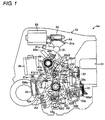
- Fig. 1 shows the internal structure of the vehicle door lock device Ao when a vehicle interior member (cover) of the housing 10 is removed.
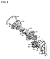
- the latch mechanism A1 is configured to hold the door in a closed state (a state where the door is closed) with respect to a body (a vehicle body (not shown)), and includes a latch 21 that is detachably engaged with a striker (not shown) fixed to the body as shown in Fig. 4 .
- a body a vehicle body (not shown)
- a latch 21 that is detachably engaged with a striker (not shown) fixed to the body as shown in Fig. 4 .
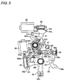
- other components of the latch mechanism A1 other than a lift lever 23 are not shown in Figs. 3 and Figs. 5 to 7 , but the exploded latch mechanism A1 is shown in Fig. 4 .
- the latch mechanism is assembled to the door while being assembled to the housing 10.
- the latch 21 is engaged with the striker, so that the latch mechanism A1 can hold the door in a closed state (can latch the door). Further, if the latch 21 is disengaged from the striker when the door is closed, the latch mechanism A1 changes the state of the door from a closed state to an open state (a state where the door can be opened with respect to the body) (the latch mechanism may unlatch the door).
- the latch mechanism A1 includes the latch 21, a pole 22, the lift lever 23, and a stopper 24, cushions C1 and C2, a torsion spring S1 for the latch, and a torsion spring S2 for the pole. These components are assembled to a base plate 25, a case 26, and a sub-base plate 27 by a screw 28 and a pin 29. Meanwhile, the base plate 25 is assembled to the door with a seal member 91 shown in Fig. 4 interposed therebetween.
- the opening mechanism A2 operates the latch mechanism A1 to an unlatched state from a latched state in order to allow the door to be opened with respect to the body.
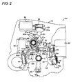
- the opening mechanism includes an outside open lever 31 (see Figs. 1 , 2 , and 4 ), an inside open lever 32 (see Fig. 1 ), and an open link 33 (see Figs. 1 to 3 and Figs. 5 to 7 ).
- the outside open lever 31 is rotatably assembled to the housing 10 together with a torsion spring S3 (a spring for urging the outside open lever 31 toward the initial position (return position) in a clockwise direction of Fig. 4 ). Further, as is known, the outside open lever is directly linked to a lower end portion 33a of the open link 33 (see Figs. 2 and 3 ) at a housing inner end portion 31a (see Figs. 2 and 4 ), and is linked to an outside door handle (not shown), which is provided on the door outside the vehicle through a link mechanism (not shown), at a housing outer end portion 31b (see Fig. 4 ) as is known.
- a torsion spring S3 a spring for urging the outside open lever 31 toward the initial position (return position) in a clockwise direction of Fig. 4 .
- the outside open lever 31 is rotated against the urging force of a torsion spring S3 by the pulling operation of the outside door handle (door opening operation). Meanwhile, a clip 31c (see Fig. 4 ) is assembled to the outside open lever 31.
- the inside open lever 32 is rotatably linked to the door, and includes first and second inside open levers 32A and 32B as shown in Fig. 1 . Further, the inside open lever includes a connecting pin 32C and a slider 32D that can connect/separate the first inside open lever with/from the second inside open lever.
- the first inside open lever 32A is rotatably assembled to a support shaft 11 provided in the housing 10, is linked to an inside door handle (not shown) that is provided on the door inside a vehicle by a known structure, and is rotated in the counterclockwise direction of Fig. 1 by the pulling operation of the inside door handle (door opening operation).
- the first inside open lever 32A includes an arc-shaped elongated hole 32a1 the center of which corresponds to the support shaft 11, and a linear elongated hole 32a2 that is formed at one end of the arc-shaped elongated hole 32a1 and extends in a radial direction of the support shaft 11. Further, the first inside open lever 32A includes a connection portion 32a3 that is connected to an inside door handle (not shown), and a protrusion 32a4 (bent portion) that can be engaged/disengaged with/from an engaging protrusion portion 41c of an active lever 41 of the lock mechanism A3 to be described below.
- the second inside open lever 32B is rotatably assembled to the support shaft 11 that is provided in the housing 10, can be rotated integrally with the first inside open lever 32A when the connecting pin 32C and the slider 32D are held at a position of Fig. 1 (connection position) (child-proof OFF state), and is separated from the first inside open lever 32A and cannot be rotated when the connecting pin 32C and the slider 32D are held at a position moved upward from the position of Fig. 1 (separation position) by a predetermined distance (child-proof ON state).
- the second inside open lever 32B can be engaged/disengaged with/from the lower surface of an L-shaped pressing portion 33c of the open link 33 at the tip portion 32b1 thereof (which is covered with a child-proof lever 32E in the state shown in Fig. 1 . Accordingly, when the first inside open lever 32A is rotated in the counterclockwise direction of Fig. 1 in the state shown in Fig. 1 , the second inside open lever is rotated integrally with the first inside open lever 32A and may press the open link 33 toward the upper side in Fig. 1 . Further, the second inside open lever 32B includes a linear arm portion 32b2 which extends in the radial direction of the support shaft 11 and to which the slider 32D is slidably fitted.
- the connecting pin 32C is integrally assembled to the slider 32D, and is fitted to the arc-shaped elongated hole 32a1 or the linear elongated hole 32a2 of the first inside open lever 32A. Accordingly, the connecting pin can be moved together with the slider 32D along the linear arm portion 32b2 of the second inside open lever 32B by the child-proof lever 32E.
- the child-proof lever 32E moves the connecting pin 32C and the slider 32D along the linear arm portion 32b2 of the second inside open lever 32B, and is tiltably assembled to the housing 10 at the middle portion thereof.
- the child-proof lever includes an operation knob 32el that protrudes to the outside of the housing 10 and may be manually operated, and an arc-shaped elongated hole 32e2 the center of which corresponds to the support shaft 11 in the child-proof OFF state shown in Fig. 1 .
- the child-proof lever 32E may be tilted to a predetermined position from the state shown in Fig. 1 in a clockwise direction.
- the connecting pin 32C is fitted to the linear elongated hole 32a2 of the first inside open lever 32A in the state shown in Fig. 1 , so that the first inside open lever 32A and the second inside open lever 32B are integrally connected to each other. For this reason, during the pulling operation of the inside door handle (not shown), the first inside open lever 32A is rotated integrally with the second inside open lever 32B and the connecting pin 32C and the slider 32D are moved along the arc-shaped elongated hole 32e2 of the child-proof lever 32E.
- the connecting pin 32C is fitted to the arc-shaped elongated hole 32a1 of the first inside open lever 32A and the connection between the first and second inside open levers 32A and 32B performed by the connecting pin 32C and the slider 32D is released. For this reason, during the pulling operation of the inside door handle (not shown), only the first inside open lever 32A is rotated and the second inside open lever 32B is not rotated.
- the open link 33 is provided between the lift lever 23 of the latch mechanism 20 and the open levers 31 and 32, and is rotatably connected to and supported by the housing inner end portion 31 a of the outside open lever 31 at the lower end portion 33a thereof. Accordingly, the open link may be rotated (moved) between an unlock position shown in Figs. 1 to 3 and a lock position shown in Figs. 5 to 7 by a panic lever 43 that is a component of the lock mechanism A3.
- the open link 33 includes an elongated hole 33b that extends in the vertical direction in the state shown in Figs. 1 to 3 and is formed between an upper end of the open link and the middle portion thereof, and a L-shaped pressing portion 33c at the middle portion.
- the pressing portion 33c can be engaged with the lift lever 23 of the latch mechanism 20 (can transmit the door opening operation of each of the open levers 31 and 32 to the lift lever 23) in order to set the door in an open state.
- the open link 33 is positioned at the lock position shown in Figs. 5 to 7 , the pressing portion cannot be engaged with the lift lever 23 of the latch mechanism 20 (cannot transmit the door opening operation of each of the open levers 31 and 32 to the lift lever 23).
- the open link 33 receives the door opening operation of the outside open lever 31 (the pulling operation of the outside door handle) at the lower end portion 33a, or receives the door opening operation of the inside open lever 32 (the pulling operation of the inside door handle) at the pressing portion 33c (in detail, the lower surface of the pressing portion). Accordingly, the open link is moved to a pressing position that is positioned on the upper side by a predetermined distance in the drawing from the shown position (return position). For this reason, when the open link 33 receives the door opening operation of the outside open lever 31 or the inside open lever 32 at the lower end portion 33a or the pressing portion 33c at the unlock position shown in Figs.
- the open link 33 receives the door opening operation of the outside open lever 31 or the inside open lever 32 at the lower end portion 33a or the pressing portion 33c at the lock position shown in Figs. 5 to 7 in the closed state of the door and is moved upward, the upper end of the pressing portion 33c of the open link 33 is not engaged with the lift lever 23 of the latch mechanism A1 and the latch mechanism At is held in the latched state. Accordingly, the door is held at the closed state. That is, when the open link 33 is positioned at the lock position shown in Figs. 5 to 7 , the door is locked.
- the lock mechanism A3 switches the open link 33 between the unlock position shown in Figs. 1 to 3 and the lock position shown in Figs. 5 to 7 .
- the lock mechanism includes an active lever 41, a locking lever 42, a panic lever 43, and a torsion spring 44.
- the active lever 41 is assembled to a support shaft 12, which is provided in the housing 10, together with the panic lever 43 and the torsion spring 44, and is rotatably supported by the support shaft 12.
- the active lever 41 includes an engagement pin portion 41a that is linked to the locking lever 42, and a stopper 41b that can be engaged/disengaged with/from a protrusion 43b of the panic lever 43. Further, the active lever 41 includes the engaging protrusion portion 41c that can be engaged/disengaged with/from the protrusion 32a4 of the first inside open lever 32A, and a locking portion 4I d that is engaged with one end of the torsion spring 44.
- the stopper 41b is formed integrally with the active lever 41, and restricts the rotation of the panic lever 43 with respect to the active lever 41 in an unlocking direction (a counterclockwise direction in the drawing) at a fixed position shown in Figs. 1 to 3 and Figs. 5 and 6 .
- the locking lever 42 is rotatably assembled to the support shaft 11.
- the locking lever includes a sector gear 42a that meshes with a worm 45, and an engagement elongated hole 42b that is linked to the engagement pin portion 41a of the active lever 41.
- the worm 45 may be rotationally driven by an electric motor 46 that can be driven in a normal direction and a reverse direction.
- the active lever 41 is adapted to be held at the unlock position (the position shown in Figs. 1 to 3 and Fig. 7 ) or the lock position (the position shown in Figs. 5 and 6 ) by a spring (not shown) that is assembled in the housing 10.
- the locking lever 42 is tilted in the locking direction and the active lever 41 is rotationally driven to the lock position shown in Figs. 5 and 6 from the unlock position shown in Figs. 1 to 3 and is held at the lock position.
- the electric motor 46 is a known electric motor that is driven according to a locking operation and an unlocking operation (for example, the remote control operation of a lock/unlock switch provided at a key blade (not shown) outside a vehicle).
- the locking lever 42 includes an operation portion 42c that is linked to a locking knob (not shown) provided on the door inside a vehicle.
- the operation portion 42c is adapted to be tilted integrally with the sector gear 42a and the engagement elongated hole 42b. Accordingly, when a locking knob (not shown), which is provided on the door inside a vehicle, is operated and the operation portion 42c is tilted, the engagement elongated hole 42b of the locking lever 42 is integrally tilted and the active lever 41 is rotationally driven. Meanwhile, the sector gear 42a is also integrally rotated in this case, so that the worm 45 and the electric motor 46 are rotated together with each other.
- the panic lever 43 is rotatably assembled to the support shaft 12 and can be rotated relative to the active lever 41 by a predetermined amount.
- the sub-lever includes an engagement pin portion 43a that is linked to the elongated hole 33b of the open link 33.
- the panic lever 43 includes a protrusion 43b that can be engaged/disengaged with/from the stopper 41b of the active lever 41 and a locking portion 43c with which the other end of the torsion spring 44 is engaged.
- the panic lever 43 includes an arm portion 43d that extends in the radial direction of the support shaft 12.
- the torsion spring 44 is provided between the active lever 41 and the panic lever 43, and urges the panic lever so that the panic lever 43 is rotated relative to the active lever 41 in the counterclockwise direction shown in Figs. 1 to 3 and Figs. 5 to 7 (unlocking direction). For this reason, in the state shown in Figs. 1 to 3 and Figs. 5 and 6 , the protrusion 43b of the panic lever 43 is elastically engaged with the stopper 41b of the active lever 41.
- the panic lever 43 is rotated integrally with the active lever 41.
- the panic lever 43 is rotated while interlocking with the active lever 41 through the torsion spring 44.
- the double-lock mechanism A4 can be switched between a double-lock set state where the operation of the lock mechanism A3 is restricted and a double-lock unset state where the operation of the lock mechanism A3 is allowed.
- the double-lock mechanism includes a double-lock lever 51.
- the double-lock lever 51 is provided in the housing 10, and is rotatably assembled to the housing 10.
- the double-lock lever can be switched between an unset position corresponding to the double-lock unset state (the position shown in Figs. 1 to 3 or Fig. 5 ) and to a set position corresponding to the double-lock set state (the position shown in Fig. 6 or 7 ).
- the double-lock lever 51 includes a sector gear 51a that meshes with a worm 52, an arm portion 51b that extends from a rotation center to the outside in the radial direction, and a protrusion 51c that is formed at the tip portion of the arm portion 51b and can be engaged/disengaged with/from the arm portion 43d of the panic lever 43 positioned at the lack position.
- the worm 52 may be rotationally driven by an electric motor 53 that can be driven in a normal direction and a reverse direction.
- the double-lock lever 51 is adapted to be held at the unset position (the position shown in Figs. 1 to 3 and Fig. 5 ) or the set position (the position shown in Figs. 6 and 7 ) by a spring (not shown) that is assembled in the housing 10.
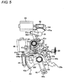
- the double-lock lever 51 is rotationally driven to the set position shown in Fig. 6 from the unset position shown in Fig. 5 and is held at the set position.
- the electric motor 53 is a known electric motor that is driven according to a setting operation and an unsetting operation (for example, the remote control operation of a set/unset switch provided at a key blade outside a vehicle).
- the movement of the panic lever 43 and the lift lever 33 to the unlock position from the lock position is set to be allowed and the movement of the active lever 41 and the locking lever 42 to the unlock position from the lock position is set to be allowed.
- the panic lever 43 and the lift lever 33 are positioned at the lock position and the double-lock lever 51 is positioned at the set position ( Fig. 6 or 7 )
- the movement of the panic lever 43 and the lift lever 33 to the unlock position from the lock position is set to be restricted and the movement of the active lever 41 and the locking lever 42 to the unlock position from the lock position is set to be allowed.
- engagement timing where the protrusion 32a4 of the first inside open lever 32A and the engaging protrusion portion 41c of the active lever 41 are engaged with each other (drive start timing where the active lever 41 starts to be driven by the inside open lever 32) is set to be delayed by a predetermined time as compared to press timing where the open link 33 is pressed by the tip portion 32b1 of the second inside open lever 32B (drive start timing where the open link 33 starts to be driven by the inside open lever 32) (set to delay timing where the open link 33 positioned at the lock position is moved to the unlock position) so that a so-called double-pulling operation is obtained with the door opening operation of the inside door handle.
- a position switch SW as position detecting unit, which can detect a position where the active lever 41 is held (the unlock position or the lock position), is provided in the housing 10.
- the position switch SW includes a contactor SWa that can be engaged/disengaged with/from a protrusion 41e formed at the active lever 41.
- the position switch is set as follows: when the active lever 41 is positioned at the unlock position (see Figs. 1 to 3 and Fig. 7 ), the protrusion 41e of the active lever 41 is engaged with the contactor SWa, so that the position switch is turned on.
- the protrusion 41e of the active lever 41 is disengaged from the contactor SWa, so that the position switch is turned off.
- the position switch SW is connected to a lock state indication lamp (not shown) or a drive circuit (not shown) of the electric motor 46 through an electrical control device (not shown) and is connected to an alarm buzzer (not shown).
- the position switch is set to stop the driving of the electric motor 46 and to turn off (or on) an indication lamp (not shown) when the electric motor 46 is driven according to a normal operation (for example, a locking operation or an unlocking operation) and the active lever 41 positioned at a lock position (or an unlock position) is moved to an unlock position (or a lock position).
- the position switch SW is set as follows: when the locking lever 42 and the active lever 41 positioned at the lock position are rotated toward the unlock position (see Fig. 7 ) in the door lock device that is in a lock state (a state shown in Fig. 5 ) or a double-lock state (a state shown in Fig. 6 ) due to an attack from the outside of a vehicle (an illegal act at the time of a burglary), an alarm buzzer (not shown) sounds the alarm. That is, in the first embodiment, the position switch SW is set so as to function even during the attack.
- the door opening operation of the inside door handle is performed when the open link 33 is positioned at the unlock position by the lock mechanism A3, the lock mechanism A3 is in the unlock state, and the double-lock mechanism A4 is in the double-lock unset state (at the time of unlocking) as shown in Figs. 1 , 2 , and 3 , the door opening operation of the inside open lever 32 is transmitted to the lift lever 23 of the latch mechanism .A1 through the open link 33, which is positioned at the unlock position, along with the door opening operation and the opening operation of the latch mechanism A1 is performed. Accordingly, the door can be opened by the door opening operation of the inside door handle.
- the door opening operation of the outside door handle is performed in this case (at the time of unlocking)
- the door opening operation of the outside open lever 31 is transmitted to the lift lever 23 of the latch mechanism A1 through the open link 33, which is positioned at the unlock position, with the door opening operation and the opening operation of the latch mechanism A1 is performed. Accordingly, the door can be opened even by the door opening operation of the outside door handle.
- the lock mechanism A3 is in the lock state
- the double-lock mechanism A4 is in the double-lock unset state (at the time of locking) as shown in Fig. 5
- a so-called double-pulling operation is obtained along with the door opening operation of the inside door handle and the opening operation of the latch mechanism A1 is performed by the double-pulling operation of the inside door handle (a first pulling operation and a second pulling operation after the inside door handle is temporarily returned). Accordingly, the door can be opened by the door opening operation of the outside door handle.
- the active lever 41, the panic lever 43, and the like are not switched to the unlock position from the lock position and the open link 33 positioned at the lock position is driven (is pressed upward) by the door opening operation of the inside open lever 32 with the door opening operation of the inside door handle, at the early and middle stages of the first door opening operation of the inside door handle (first pulling operation). Further, the active lever 41, the panic lever 43, and the like are switched to the unlock position from the lock position and the open link 33 continues to be driven (is pressed upward) by the door opening operation of the inside open lever 32 at the latter stage of the first pulling operation.
- the movement of the open link 33 is not transmitted to the lift lever 23 of the latch mechanism A1 and the latch mechanism A1 is maintained in the closed state (latched state), so that the door cannot be opened.
- the active lever 41, the panic lever 43, and the like are switched to the unlock position from the lock position at the latter stage of the first pulling operation, so that the open link 33 is switched to the unlock position from the lock position.
- the open link 33 is driven (is pressed upward) by a predetermined distance and is in a so-called panic state (a state where the side surface of the pressing portion 33c of the open link 33 is engaged with the side portion of the lift lever 23). Accordingly, since a driving force is not transmitted to the lift lever 23 of the latch mechanism A1 from the open link 33, the opening operation of the latch mechanism A1 is not performed, so that the door cannot be opened.
- the active lever 41 is switched to the unlock position and held.
- the panic lever 43 is rotated relative to the active lever 41 against the urging force of the torsion spring 44 by a predetermined amount, the panic lever 43 is not switched to the unlock position.
- the panic lever 43 is rotated relative to the active lever 41 in the unlocking direction by the urging force of the torsion spring 44 while the open link 33 is moved to the return position when the inside door handle is temporarily returned, the above-described panic state is released, so that the panic lever 43 and the open link 33 are switched to the unlock position.
- the door opening operation of the inside open lever 32 is transmitted to the lift lever 23 of the latch mechanism A1 through the open link 33, which is positioned at the unlock position, with the door opening operation of the inside door handle like at the time of the above-described unlocking. Therefore, the opening operation of the latch mechanism A1 is performed, so that the door can be opened by the second door opening operation of the inside door handle.
- the lock mechanism A3 is in the lock state
- the double-lock mechanism A4 is in the double-lock set state (at the time of double-locking) as shown in Fig. 6
- the panic lever 43 and the open link 33 are positioned at the lock position
- the double-lock lever 51 is positioned at the set position
- the movement of the panic lever 43 to the unlock position is restricted by the double-look lever 51
- the movement of the active lever 41 from the fixed position (the position shown in Fig. 6 ) against the urging force of the torsion spring 44 (the movement in the unlocking direction) is allowed.
- the active lever 41 misses the panic lever 43 and the open link 33, so that the panic lever 43 and the open link 33 positioned at the lock position are not rotated toward the unlock position. Accordingly, the panic lever 43 of the lock mechanism A3 is maintained in the lock state in this case, so that the door cannot be opened by the door opening operation of the inside door handle.
- the active lever 41, the panic lever 43, and the like are not switched to the unlock position from the lock position and the open link 33 is maintained at the lock position.
- the door opening operation of the outside door handle is performed at the time of the above-described locking and double-locking, the door opening operation of the outside open lever 31 is transmitted to the open link 33, which is positioned at the lock position, with the door opening operation but is not transmitted to the lift lever 23 of the latch mechanism A1 from the open link 33 that is positioned at the look position. Accordingly, the opening operation of the latch mechanism A1 is not performed in this case, so that the door cannot be opened by the door opening operation of the outside door handle.
- the panic lever 43 may be rotated relative to the double-lock lever 51 while being connected to the active lever by the torsion spring 44 and the stopper 41b provided at the active lever 41 so as to be rotated integrally with the active lever 41. Accordingly, when the active lever 41 is rotated in the unlocking direction by the door opening operation of the inside open lever 32 with the door opening operation of the inside door handle, the panic lever 43 is rotated integrally with the active lever 41 in the unlocking direction. Therefore, the delay of the door opening operation of the inside door handle does not occur at the early stage of the movement of the active lever 41 and the panic lever 43 to the unlock position from the lock position. As a result, the operation feeling does not deteriorate at the time of the door opening operation of the inside door handle.
- the position switch SW as position detecting unit, which can detect a position where the active lever 41 is held (the unlock position or the lock position), is provided in the first embodiment.
- the position switch SW is connected to the alarm buzzer (not shown) through the electrical control device (not shown).
- the position switch SW is set so as to sound the alarm when the active lever 41 and the locking lever 42 are rotated toward the unlock position in the lock state (the state shown in Fig. 5 ) or the double-lock state (the state shown in Fig. 6 ) (for example, see Fig. 7 ).
- an attack made against the door lock device from the outside of a vehicle for example, an attack made against the locking lever 42 (connected to the locking knob that may be attacked from the outside of the vehicle), which is connected to the active lever 41 so as to be capable of interlocking with the active lever, from the outside of a vehicle may be detected by the position switch SW.
- the attack made against the door lock device from the outside of a vehicle may be detected by the position switch SW and the alarm may be sounded at the time of the attack, it is possible to improve the security of the door lock device.
- the double-lock lever 51 may be engaged/disengaged with/from the arm portion 43d of the panic lever 43 (that is movable only between the unlock position and the lock position in the housing 10) that is held at the lock position. For this reason, like in a second embodiment shown in Fig.
- the moving space of a portion (arm portion 33d) capable of being engaged/disengaged with/from the double-lock lever 51 is secured, although being small, as compared to when a portion (arm portion) capable of being engaged/disengaged with/from the double-lock lever 51 through a link 52 is formed at the open link 33 (a member which is movable between the unlock position and the lock position in the housing 10, is movable between a pressing position where the open link may be engaged with the lift lever 23 and a return position where the open link is separated from the lift lever 23, and is movable in a range wider than the moving range of the panic lever 43). Accordingly, it is possible to reduce the size of the door lock device.
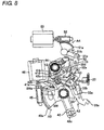
- the arm portion 33d is formed at the open link 33 in the second embodiment shown in Fig. 8 .
- a link 52 is provided between the double-lock lever 51 and the arm portion 33d of the open link 33.
- the link 52 is rotatably assembled to a support pin 13 that is provided at the housing 10, is rotatably connected to the protrusion 51c of the double-lock lever 51 at one end thereof, and can be engaged/disengaged with/from the arm portion 33d of the open link 33 at a protrusion 52a that is formed at the other end thereof.
- the inventive concept is applied to the vehicle door lock device Ao, which is adapted to obtain a so-called double-pulling operation with the door opening operation of the inside door handle.
- the inventive concept may also be applied to a vehicle door lock device, which is adapted to obtain a so-called one-motion operation along with the door opening operation of the inside door handle (is adapted to advance timing, where the open link 33 positioned at the lock position is moved to the unlock position, as compared to the above-described embodiment), in the same manner.
- the inventive concept may be adapted not to obtain the above-described double-pulling operation or one-motion operation, and may be adapted so that the active lever 41 is rotated in the unlocking direction while being linked to the lock releasing operation of the locking knob provided on the door inside a vehicle.
- the first and second inside open levers 32A and 32B of the inside open lever 32 are connected/separated to/from each other by the connecting pin 32C and the slider 32D that are moved by the child-proof lever 32E.
- the inventive concept may be applied to a vehicle door lock device, where a portion corresponding to the first inside open lever 32A of the inside open lever and a portion corresponding to the second inside open lever 32B of the inside open lever are formed integrally with each other, (a vehicle door lock device where a child-proof function is not set) in the same manner.
- the locking lever 42 is connected to the locking knob (not shown), which is provided on the door inside a vehicle, so as to be capable of interlocking with the locking knob.
- the locking lever 42 may not be connected to the locking knob (the locking knob may not be provided).
- the inventive concept is applied to the vehicle door lock device Ao that is mounted on a right rear door provided on the right rear portion of a vehicle.
- the inventive concept may also be applied to not only a vehicle door lock device that is mounted on a left rear door but also a vehicle door lock device that is mounted on a right front door or left front door, in the same manner.
- the housing 10 is employed in the above-described first embodiment.
- a base plate to which the latch mechanism A1, the opening mechanism A2, the lock mechanism A3, the double-lock mechanism A4, and the like are assembled; and a protector that protects the latch mechanism A1, the opening mechanism A2, the lock mechanism A3, the double-lock mechanism A4, and the like may be employed instead of the housing.
- the active lever 41 could be directly engaged with the inside open lever 32 (the protrusion 32a4 of the first inside open lever 32A) in the above-described first embodiment.
- the active lever may be indirectly engaged with and linked to the inside open lever, for example, through the locking lever.
- the lock mechanism A3 is adapted to be locked or unlocked by the operation of the locking knob (not shown) or the electric motor 46 and the double-lock mechanism A4 is adapted to be set or unset by the operation of the electric motor 53.
- an emergency release mechanism A5 which is operated through the mechanical rotation performed by the operation member (not shown) such as a key blade, may be provided like in a third embodiment shown in Fig. 9 .
- the emergency release mechanism A5 shown in Fig. 9 is rotatably assembled to the housing 10, and includes a key lever 61 that may be mechanically rotated.
- the emergency release mechanism is set as follows: the key lever 61 is rotated from the lock position (the position of Fig. 9 ) toward the unlock position (in a direction of an arrow shown in Fig. 9 ), so that the double-lock lever 51 is moved to the unset position from the set position and the active lever 41 is moved to the unlock position from the lock position.
- the key lever 61 is provided on a door.
- the key lever is connected to a key cylinder (not shown), which may be rotated by a mechanical operation performed by a key blade (not shown) from the outside of a vehicle, through a link mechanism (not shown). Accordingly, the key lever may be mechanically rotated by the key blade (not shown).
- the key lever 61 includes a long arm portion 61a and a short arm portion 61b. In the state shown in Fig. 9 , the long arm portion 61a is engaged with a protrusion 51e that is formed at a second arm portion 51d of the double-lock lever 51, and is engaged with a protrusion 41g, which is formed at an arm portion 41f of the active lever 41, through a link 62. Accordingly, when the key lever 61 is rotated in the direction of the arrow shown in Fig. 9 , the double-lock lever 51 is moved to the unset position from the set position and the active lever 41 is moved to the unlock position from the lock position.
- the link 62 is rotatably assembled to a support shaft 14 that is provided at the housing 10.
- the link is connected to the protrusion 41g of the active lever 41 at an elongated hole 62a that is formed at one end of the link, and is adapted to be capable of being engaged/disengaged with/from the long arm portion 61a of the key lever 61 at a protrusion 62b that is formed at the other end of the link.
- the protrusion 62b of the link 62 is also adapted to be capable of being engaged/disengaged with/from the short arm portion 61b of the key lever 61.
- the emergency release of the door lock device which is in the state shown in Fig. 9 (double-lock state), (the release operation of the door lock device to the unlock state) may be performed by the mechanical rotation of a key blade (not shown) (the rotation in the counterclockwise direction of Fig. 9 ).
- the locking operation of the door lock device, which is in the unlock state (the operation of the door lock device to the lock state) may be performed by the mechanical rotation of a key blade (not shown) (the rotation of the key blade in the clockwise direction of Fig. 9 ).
- the key lever 61 is adapted to be capable of being rotated even by the mechanical operation that is performed by a tool (not shown) from the inside of a vehicle, the emergency release may also be performed from the inside of a vehicle.
Landscapes
- Lock And Its Accessories (AREA)
Abstract
Description
- The disclosure relates to a vehicle door lock device, and more particularly, to a double-lock type vehicle door lock device that includes a lock mechanism and a double-lock mechanism.
-
JP-A-2002-38797 - Further,
JP-A-2006-233507 JP-A-2006-233507 - If the open link is positioned at the lock position and the inside open lever is operated in a door opening direction with the door opening operation of the inside door handle when the double-lock mechanism is in the double-lock unset state and the operation of the lock mechanism is allowed in the vehicle door lock device disclosed in
JP-A-2002-38797 - The vehicle door lock device disclosed in
JP-A-2002-38797 JP-A-2002-38797 - Therefore, at the time of the above-described one-motion operation or the operation of the locking knob, the hooked lever is elastically deformed and transmits a force to the active lever while being bent and the delay of the door opening operation of the inside door handle or the operation of the locking knob occurs at the early stage of the movement of the active lever to the unlock position from the lock position. Accordingly, there is a concern that the operation feeling deteriorates. Meanwhile, it may be possible to reduce the bending of the above-described hooked lever by changing the shape, the material, and the like of the hooked lever. However, in this case, there is a concern that the size or cost of the device is increased.
- A need thus exists for a double-lock type vehicle door lock device that can be smoothly switched to an unlock state even in a panic state without deteriorating the operation feeling of a mechanical operation member (an inside door handle or a locking knob) capable of moving an active lever to an unlock position from a lock position.
- Accoridng to an aspect of this disclosure, a double-lock type vehicle door lock device includes: a latch mechanism that is assembled to a door of a vehicle and is configured to hold the door in a closed state with respect to a body; an inside open lever that is rotatably linked to the door and is driven with the operation of an inside door handle provided on the door inside the vehicle; an open link that is rotatably linked to the door, is provided between the inside open lever and a lift lever of the latch mechanism, and is switchable between an unlock position where a door opening operation of the inside open lever is transmitted to the lift lever and a lock position where the door opening operation is not transmitted to the lift lever, with a door opening operation of the inside door handle; a lock mechanism that switches the open link between the unlock position and the lock position; and a double-lock mechanism that is switchable between a double-lock set state where an operation of the lock mechanism is restricted and a double-lock unset state where the operation of the lock mechanism is allowed. The lock mechanism includes: an active lever that is rotatably linked to the door, is held at either one of the unlock position and the lock position, and is moved to the unlock position from the lock position while being linked to the door opening operation of the inside open lever or a lock releasing operation of a locking knob provided on the door inside the vehicle; a panic lever that is assembled to the active lever to be rotatable relative to the active lever by a predetermined amount, is linked to the open link, and switches the open link between the unlock position and the lock position; a stopper that is provided at the active lever and restricts the rotation of the panic lever in an unlocking direction at a fixed position; and an urging member that urges the panic lever toward the fixed position in the unlocking direction. When the open link is switched to the lock position from the unlock position by a movement of the active lever to the lock position from the unlock position, the panic lever is operated integrally with the active lever. When the open link is switched to the unlock position from the lock position by a movement of the active lever to the unlock position from the lock position, the panic lever is set to interlock with the active lever through the urging member. The double-lock mechanism includes a double-lock lever that is rotatably linked to the door and is switchable between an unset position corresponding to the double-lock unset state and a set position corresponding to the double-lock set state. When the panic lever and the open link are positioned at the lock position and the double-lock lever is positioned at the unset position, a movement of the panic lever and the open link to the unlock position from the lock position is allowed and a movement of the active lever to the unlock position from the lock position is allowed. When the panic lever and the open link are positioned at the lock position and the double-lock lever is positioned at the set position, the movement of the panic lever and the open link to the unlock position from the lock position is restricted and the movement of the active lever to the unlock position from the lock position is allowed.
- It is noted that, when the double-lock mechanism is in the double-lock unset state (when the door lock device is in the lock state), the active lever may be engaged with the inside open lever moved to the unlock position from the lock position by the door opening operation of the inside open lever. In this case, when the door lock device is in the lock state, the door lock device may be set so that a so-called one-motion operation or double-pulling operation is performed by the door opening operation of the inside door handle.
- If the door opening operation of the inside door handle is performed when the open link is positioned at the unlock position by the lock mechanism, the lock mechanism is in the unlock state, and the double-lock mechanism is in the double-lock unset state (at the time of unlocking) in the above-described double-lock type vehicle door lock device, the door opening operation of the inside open lever is transmitted to the lift lever of the latch mechanism through the open link that is positioned at the unlock position, with the door opening operation. Accordingly, the opening operation of the latch mechanism is performed and the door can be opened by the door opening operation of the inside door handle.
- Meanwhile, a general vehicle door lock device also includes an outside open lever that is driven with the operation of an outside door handle provided on a door outside of a vehicle. The open link is set so as to be driven by not only the door opening operation of the inside open lever accompanying the door opening operation of the inside door handle but also the door opening operation of the outside open lever accompanying the door opening operation of the outside door handle. For this reason, if the door opening operation of the outside door handle is performed in this case (at the time of unlocking), the door opening operation of the outside open lever is transmitted to the lift lever of the latch mechanism through the open link, which is positioned at the unlock position, with the door opening operation and the opening operation of the latch mechanism is performed. Accordingly, the door can be opened even by the door opening operation of the outside door handle.
- Further, if the door lock device is set so that a so-called double-pulling operation is set to be obtained with the door opening operation of the inside door handle, when the open link is positioned at the lock position by the lock mechanism, the lock mechanism is in the lock state, and the double-lock mechanism is in the double-lock unset state (at the time of locking), the opening operation of the latch mechanism is performed by the double-pulling operation of the inside door handle (a first pulling operation and a second pulling operation after the inside door handle is temporarily returned). Accordingly, the door can be opened.
- In this case (at the time of locking), the active lever, the panic lever, and the like are not switched to the unlock position from the lock position and the open link positioned at the lock position is driven by the door opening operation of the inside open lever with the door opening operation of the inside door handle, at the early and middle stages of the first door opening operation of the inside door handle (first pulling operation). Further, the active lever, the panic lever, and the like are switched to the unlock position from the lock position and the open link continues to be driven by the door opening operation of the inside open lever at the latter stage of the first pulling operation.
- For this reason, at the early and middle stages of the first pulling operation, the movement of the open link is not transmitted to the lift lever of the latch mechanism and the latch mechanism is maintained in the closed state (latched state), so that the door cannot be opened. Further, the active lever, the panic lever, and the like are switched to the unlock position from the lock position at the latter stage of the first pulling operation, so that the open link is switched to the unlock position from the lock position. However, in this case, the open link is driven by a predetermined distance and is in a so-called panic state. Accordingly, since a driving force is not transmitted to the lift lever of the latch mechanism from the open link, the opening operation of the latch mechanism is not performed, so that the door cannot be opened.
- In the above-described panic state, the active lever is switched to the unlock position and held. However, since the panic lever is rotated relative to the active lever against the urging force of the urging member by a predetermined amount, the panic lever is not switched to the unlock position. For this reason, if the panic lever is rotated relative to the active lever in the unlocking direction by the urging force of the urging member while the open link is moved to the return position when the inside door handle is temporarily returned, the above-described panic state is released, so that the panic lever and the open link are switched to the unlock position.
- Accordingly, since the active lever, the panic lever, and the like are switched to the unlock position and the open link is moved to the unlock position at the time of the second pulling operation of the inside door handle, the door opening operation of the inside open lever is transmitted to the lift lever of the latch mechanism through the open link, which is positioned at the unlock position, with the door opening operation of the inside door handle like at the time of unlocking. Therefore, the opening operation of the latch mechanism is performed, so that the door can be opened by the second door opening operation of the inside door handle.
- Further, when the open link is positioned at the lock position by the lock mechanism, the lock mechanism is in the lock state, and the double-lock mechanism is in the double-lock set state (at the time of double-locking), the panic lever and the open link are positioned at the lock position, the double-lock lever is positioned at the set position, the movement of the panic lever and the open link to the unlock position is restricted by the double-lock lever, and the movement of the active lever from the fixed position against the urging force of the urging member (the movement in the unlocking direction) is allowed.
- For this reason, regardless of which door opening operation of the inside door handle is performed in this case (at the time of double-locking), the active lever misses the panic lever and the open link at the latter stage of the door opening operation, so that the panic lever and the open link positioned at the lock position are not rotated toward the unlock position. Accordingly, the panic lever of the lock mechanism is maintained in the lock state in this case, so that the door cannot be opened by the door opening operation of the inside door handle.
- Meanwhile, regardless of which door opening operation of the outside door handle is performed at the time of the above-described locking and double-locking, the active lever, the panic lever, and the like are not switched to the unlock position from the lock position and the open link is maintained at the lock position. For this reason, if the door opening operation of the outside door handle is performed at the time of the above-described locking and double-locking, the door opening operation of the outside open lever is transmitted to the open link, which is positioned at the lock position, along with the door opening operation but is not transmitted to the lift lever of the latch mechanism from the open link that is positioned at the lock position. Accordingly, the opening operation of the latch mechanism is not performed in this case, so that the door cannot be opened by the door opening operation of the outside door handle.
- A case where the door lock device is set so that a so-called double-pulling operation is obtained with the door opening operation of the inside door handle at the time of the locking of the door lock device has been described above. However, the above-described door lock device may be set so that a so-called one-motion operation is obtained with the door opening operation of the inside door handle. In this case, the opening operation of the latch mechanism is performed by a single pulling operation of the inside door handle (one pulling operation), so that the door can be opened. Further, the above-described door lock device may be set so that a so-called one-motion operation (or a double-pulling operation) is not obtained, and the active lever may be moved to the unlock position from the lock position while being linked to a lock releasing operation of a locking knob provided on the door inside a vehicle.
- Meanwhile, in the above-described the door lock, the panic lever is rotated relative to the double-lock lever while being connected to the active lever by the urging member and the stopper provided at the active lever so as to be rotated integrally with the active lever. Accordingly, when the active lever is rotated in the unlocking direction while being linked to the door opening operation of the inside open lever with the door opening operation of the inside door handle or the lock releasing operation of the locking knob provided on the door inside a vehicle, the panic lever is rotated integrally with the active lever in the unlocking direction. Therefore, the delay of the door opening operation of the inside door handle or the lock releasing operation of the locking knob does not occur at the early stage of the movement of the active lever and the panic lever to the unlock position from the lock position. As a result, the operation feeling does not deteriorate at the time of the door opening operation of the inside door handle or the lock releasing operation of the locking knob.
- Further, when a panic state is generated with the door opening operation of the inside door handle in the lock state in the above-described door lock device, it is possible to switch the panic lever to the unlock position by temporarily returning the inside door handle as described above and to easily release the panic state.
- The above-described door lock device may include a locking lever that is rotatably linked to the door and is connected to the active lever so as to interlock with the active lever, and position detecting unit that detects a position where the active lever is held (the unlock position or the lock position). In this case, an attack made against the door lock device from the outside of a vehicle (an illegal act at the time of a burglary), for example, an attack made against the locking lever (connected to the locking knob that may be attacked from the outside of a vehicle), which is connected to the active lever so as to interlock with the active lever, from the outside of a vehicle may be detected by the position detecting unit. For this reason, the door lock device may be set so that the attack made against the door lock device from the outside of a vehicle is detected by the position detecting unit and, for example, the alarm is sounded at the time of the attack. Accordingly, it is possible to improve the security of the door lock device.
- Further, in the above-described door lock device, it is preferable that the double-lock lever be engageable with and disengageable from the panic lever held at the lock position. In this case (that is, when a portion capable of being engaged/disengaged with/from the double-look lever is formed at the panic lever that is movable only between the unlock position and the lock position), the moving space of a portion capable of being engaged/disengaged with/from the double-lock lever is secured, although being small, as compared to when a portion capable of being engaged/disengaged with/from the double-lock lever is formed at the open link (a member which is movable between the unlock position and the lock position, is movable between a pressing position where the open link may be engaged with the lift lever and a return position where the open link is separated from the lift lever, and is movable in a range wider than the moving range of the panic lever). Accordingly, it is possible to reduce the size of the door lock device.
- Furthermore, in the above-described door lock device may include a key lever that is rotatably linked to the door and is mechanically rotated by an operation member such as a key blade, and may be set so that the double-lock lever is moved to the unset position from the set position and the active lever is moved to the unlock position from the lock position by the rotation of the key lever from a lock position toward an unlock position. In this case, the key lever may be rotated toward the unlock position from the look position by the mechanical rotation performed by the operation member such as the key blade. Accordingly, the double-lock lever may be moved to the unset position from the set position, and the active lever may be moved to the unlock position from the lock position. Therefore, for example, the emergency release of the door lock device may be carried out by the mechanical rotation performed by the operation member such as the key blade.
- In the above-described double-lock type vehicle door lock device may further include a housing that houses the inside open lever, the open link, the lock mechanism and the double-lock mechanism, and the housing may be assembled to the door together with the latch mechanism.
- The foregoing and additional features and characteristics of this disclosure will become more apparent from the following detailed description considered with the reference to the accompanying drawings, wherein:
-
Fig. 1 is a side view of a double-lock type vehicle door lock device according to a first embodiment disclosed here as seen from the inside of a vehicle when a vehicle interior member of a housing is removed; -
Fig. 2 is a side view showing a state where an inside open lever is removed from the vehicle door lock device shown inFig. 1 ; -
Fig. 3 is a side view of the structure of main parts of the vehicle door lock device when a lock mechanism of the vehicle door lock device shown inFig. 2 is in an unlock state and a double-lock mechanism is in a double-lock unset state (at the time of unlocking), as seen from the inside of a vehicle; -
Fig. 4 is an exploded perspective view of a latch mechanism of the vehicle door lock device shown inFig. 1 . -
Fig. 5 is a side view of the structure of main parts of the vehicle door lock device when the lock mechanism of the vehicle door lock device shown inFig. 2 is in a lock state and the double-lock mechanism is in a double-lock unset state (at the time of locking), as seen from the inside of a vehicle; -
Fig. 6 is a side view of the structure of main parts of the vehicle door lock device when the lock mechanism of the vehicle door lock device shown inFig. 2 is in a lock state and the double-lock mechanism is in a double-lock set state (at the time of double locking), as seen from the inside of a vehicle; -
Fig. 7 is a side view of the vehicle door lock device when an inside door handle is operated to open a door in the state shown inFig. 6 or when a locking lever is operated to be in an unlock position; -
Fig. 8 is a side view of the structure of main parts of a double-lock type vehicle door lock device according to a second embodiment disclosed here as seen from the inside of a vehicle, wherein a portion capable of being engaged with a double-lock lever is formed at an open link; and -
Fig. 9 is a side view of the structure of main parts of a double-lock type vehicle door lock device according to a third embodiment disclosed here as seen from the inside of a vehicle, wherein a key lever capable of being mechanically rotated is provided, and the key lever is rotated toward an unlock position from a lock position, so that a double-lock lever is moved to an unset position from a set position and an active lever is moved to an unlock position from a lock position. - Embodiments disclosed here will be described below.
Figs. 1 to 7 show a double-lock type vehicle door lock device Ao according to a first embodiment. The vehicle door lock device Ao is mounted on a right rear door (not shown) that is provided on the right rear portion of a vehicle, and includes a latch mechanism A1 and ahousing 10 that is assembled to the door together with the latch mechanism A1. Further, the vehicle door lock device Ao includes an opening mechanism A2, a lock mechanism A3, and a double-lock mechanism A4 that are assembled to thehousing 10. Meanwhile,Fig. 1 shows the internal structure of the vehicle door lock device Ao when a vehicle interior member (cover) of thehousing 10 is removed. - The latch mechanism A1 is configured to hold the door in a closed state (a state where the door is closed) with respect to a body (a vehicle body (not shown)), and includes a
latch 21 that is detachably engaged with a striker (not shown) fixed to the body as shown inFig. 4 . Meanwhile, for example, other components of the latch mechanism A1 other than alift lever 23 are not shown inFigs. 3 andFigs. 5 to 7 , but the exploded latch mechanism A1 is shown inFig. 4 . The latch mechanism is assembled to the door while being assembled to thehousing 10. - The
latch 21 is engaged with the striker, so that the latch mechanism A1 can hold the door in a closed state (can latch the door). Further, if thelatch 21 is disengaged from the striker when the door is closed, the latch mechanism A1 changes the state of the door from a closed state to an open state (a state where the door can be opened with respect to the body) (the latch mechanism may unlatch the door). - As shown in
Fig. 4 , the latch mechanism A1 includes thelatch 21, a pole 22, thelift lever 23, and astopper 24, cushions C1 and C2, a torsion spring S1 for the latch, and a torsion spring S2 for the pole. These components are assembled to abase plate 25, acase 26, and asub-base plate 27 by ascrew 28 and apin 29. Meanwhile, thebase plate 25 is assembled to the door with aseal member 91 shown inFig. 4 interposed therebetween. - The opening mechanism A2 operates the latch mechanism A1 to an unlatched state from a latched state in order to allow the door to be opened with respect to the body. The opening mechanism includes an outside open lever 31 (see
Figs. 1 ,2 , and4 ), an inside open lever 32 (seeFig. 1 ), and an open link 33 (seeFigs. 1 to 3 andFigs. 5 to 7 ). - The outside
open lever 31 is rotatably assembled to thehousing 10 together with a torsion spring S3 (a spring for urging the outsideopen lever 31 toward the initial position (return position) in a clockwise direction ofFig. 4 ). Further, as is known, the outside open lever is directly linked to alower end portion 33a of the open link 33 (seeFigs. 2 and3 ) at a housinginner end portion 31a (seeFigs. 2 and4 ), and is linked to an outside door handle (not shown), which is provided on the door outside the vehicle through a link mechanism (not shown), at a housingouter end portion 31b (seeFig. 4 ) as is known. For this reason, the outsideopen lever 31 is rotated against the urging force of a torsion spring S3 by the pulling operation of the outside door handle (door opening operation). Meanwhile, aclip 31c (seeFig. 4 ) is assembled to the outsideopen lever 31. - The inside
open lever 32 is rotatably linked to the door, and includes first and second insideopen levers 32A and 32B as shown inFig. 1 . Further, the inside open lever includes a connectingpin 32C and aslider 32D that can connect/separate the first inside open lever with/from the second inside open lever. The first inside open lever 32A is rotatably assembled to asupport shaft 11 provided in thehousing 10, is linked to an inside door handle (not shown) that is provided on the door inside a vehicle by a known structure, and is rotated in the counterclockwise direction ofFig. 1 by the pulling operation of the inside door handle (door opening operation). - The first inside open lever 32A includes an arc-shaped elongated hole 32a1 the center of which corresponds to the
support shaft 11, and a linear elongated hole 32a2 that is formed at one end of the arc-shaped elongated hole 32a1 and extends in a radial direction of thesupport shaft 11. Further, the first inside open lever 32A includes a connection portion 32a3 that is connected to an inside door handle (not shown), and a protrusion 32a4 (bent portion) that can be engaged/disengaged with/from an engagingprotrusion portion 41c of anactive lever 41 of the lock mechanism A3 to be described below. - The second inside
open lever 32B is rotatably assembled to thesupport shaft 11 that is provided in thehousing 10, can be rotated integrally with the first inside open lever 32A when the connectingpin 32C and theslider 32D are held at a position ofFig. 1 (connection position) (child-proof OFF state), and is separated from the first inside open lever 32A and cannot be rotated when the connectingpin 32C and theslider 32D are held at a position moved upward from the position ofFig. 1 (separation position) by a predetermined distance (child-proof ON state). - As is known, the second inside
open lever 32B can be engaged/disengaged with/from the lower surface of an L-shapedpressing portion 33c of theopen link 33 at the tip portion 32b1 thereof (which is covered with a child-proof lever 32E in the state shown inFig. 1 . Accordingly, when the first inside open lever 32A is rotated in the counterclockwise direction ofFig. 1 in the state shown inFig. 1 , the second inside open lever is rotated integrally with the first inside open lever 32A and may press theopen link 33 toward the upper side inFig. 1 . Further, the second insideopen lever 32B includes a linear arm portion 32b2 which extends in the radial direction of thesupport shaft 11 and to which theslider 32D is slidably fitted. - The connecting
pin 32C is integrally assembled to theslider 32D, and is fitted to the arc-shaped elongated hole 32a1 or the linear elongated hole 32a2 of the first inside open lever 32A. Accordingly, the connecting pin can be moved together with theslider 32D along the linear arm portion 32b2 of the second insideopen lever 32B by the child-proof lever 32E. - The child-
proof lever 32E moves the connectingpin 32C and theslider 32D along the linear arm portion 32b2 of the second insideopen lever 32B, and is tiltably assembled to thehousing 10 at the middle portion thereof. The child-proof lever includes an operation knob 32el that protrudes to the outside of thehousing 10 and may be manually operated, and an arc-shaped elongated hole 32e2 the center of which corresponds to thesupport shaft 11 in the child-proof OFF state shown inFig. 1 . - The child-
proof lever 32E may be tilted to a predetermined position from the state shown inFig. 1 in a clockwise direction. The connectingpin 32C is fitted to the linear elongated hole 32a2 of the first inside open lever 32A in the state shown inFig. 1 , so that the first inside open lever 32A and the second insideopen lever 32B are integrally connected to each other. For this reason, during the pulling operation of the inside door handle (not shown), the first inside open lever 32A is rotated integrally with the second insideopen lever 32B and the connectingpin 32C and theslider 32D are moved along the arc-shaped elongated hole 32e2 of the child-proof lever 32E. - Further, when the child-
proof lever 32E is tilted to a predetermined position, the connectingpin 32C is fitted to the arc-shaped elongated hole 32a1 of the first inside open lever 32A and the connection between the first and second insideopen levers 32A and 32B performed by the connectingpin 32C and theslider 32D is released. For this reason, during the pulling operation of the inside door handle (not shown), only the first inside open lever 32A is rotated and the second insideopen lever 32B is not rotated. - The
open link 33 is provided between thelift lever 23 of the latch mechanism 20 and theopen levers inner end portion 31 a of the outsideopen lever 31 at thelower end portion 33a thereof. Accordingly, the open link may be rotated (moved) between an unlock position shown inFigs. 1 to 3 and a lock position shown inFigs. 5 to 7 by apanic lever 43 that is a component of the lock mechanism A3. - The
open link 33 includes anelongated hole 33b that extends in the vertical direction in the state shown inFigs. 1 to 3 and is formed between an upper end of the open link and the middle portion thereof, and a L-shapedpressing portion 33c at the middle portion. When theopen link 33 is positioned at the unlock position shown inFigs. 1 to 3 , thepressing portion 33c can be engaged with thelift lever 23 of the latch mechanism 20 (can transmit the door opening operation of each of theopen levers open link 33 is positioned at the lock position shown inFigs. 5 to 7 , the pressing portion cannot be engaged with thelift lever 23 of the latch mechanism 20 (cannot transmit the door opening operation of each of theopen levers - Further, the
open link 33 receives the door opening operation of the outside open lever 31 (the pulling operation of the outside door handle) at thelower end portion 33a, or receives the door opening operation of the inside open lever 32 (the pulling operation of the inside door handle) at thepressing portion 33c (in detail, the lower surface of the pressing portion). Accordingly, the open link is moved to a pressing position that is positioned on the upper side by a predetermined distance in the drawing from the shown position (return position). For this reason, when theopen link 33 receives the door opening operation of the outsideopen lever 31 or the insideopen lever 32 at thelower end portion 33a or thepressing portion 33c at the unlock position shown inFigs. 1 to 3 in the closed state of the door and is moved upward, thelift lever 23 of the latch mechanism A1 is pushed and rotated by the upper end of thepressing portion 33c of theopen link 33 and the latch mechanism A1 is operated to the unlatched state from the latched state. Accordingly, the state of the door is changed to the open state from the closed state. That is, when theopen link 33 is positioned at the unlock position shown inFigs. 1 to 3 , the door is unlocked. - Meanwhile, when the
open link 33 receives the door opening operation of the outsideopen lever 31 or the insideopen lever 32 at thelower end portion 33a or thepressing portion 33c at the lock position shown inFigs. 5 to 7 in the closed state of the door and is moved upward, the upper end of thepressing portion 33c of theopen link 33 is not engaged with thelift lever 23 of the latch mechanism A1 and the latch mechanism At is held in the latched state. Accordingly, the door is held at the closed state. That is, when theopen link 33 is positioned at the lock position shown inFigs. 5 to 7 , the door is locked. - The lock mechanism A3 switches the
open link 33 between the unlock position shown inFigs. 1 to 3 and the lock position shown inFigs. 5 to 7 . The lock mechanism includes anactive lever 41, a lockinglever 42, apanic lever 43, and atorsion spring 44. Theactive lever 41 is assembled to asupport shaft 12, which is provided in thehousing 10, together with thepanic lever 43 and thetorsion spring 44, and is rotatably supported by thesupport shaft 12. - The
active lever 41 includes anengagement pin portion 41a that is linked to the lockinglever 42, and astopper 41b that can be engaged/disengaged with/from aprotrusion 43b of thepanic lever 43. Further, theactive lever 41 includes the engagingprotrusion portion 41c that can be engaged/disengaged with/from the protrusion 32a4 of the first inside open lever 32A, and a locking portion 4I d that is engaged with one end of thetorsion spring 44. Thestopper 41b is formed integrally with theactive lever 41, and restricts the rotation of thepanic lever 43 with respect to theactive lever 41 in an unlocking direction (a counterclockwise direction in the drawing) at a fixed position shown inFigs. 1 to 3 andFigs. 5 and6 . - The locking
lever 42 is rotatably assembled to thesupport shaft 11. The locking lever includes asector gear 42a that meshes with aworm 45, and an engagement elongatedhole 42b that is linked to theengagement pin portion 41a of theactive lever 41. Accordingly, theworm 45 may be rotationally driven by anelectric motor 46 that can be driven in a normal direction and a reverse direction. Meanwhile, theactive lever 41 is adapted to be held at the unlock position (the position shown inFigs. 1 to 3 andFig. 7 ) or the lock position (the position shown inFigs. 5 and6 ) by a spring (not shown) that is assembled in thehousing 10. - Accordingly, when the
worm 45 is rotationally driven in a locking direction by theelectric motor 46, the lockinglever 42 is tilted in the locking direction and theactive lever 41 is rotationally driven to the lock position shown inFigs. 5 and6 from the unlock position shown inFigs. 1 to 3 and is held at the lock position. Further, when theworm 45 is rotationally driven in an unlocking direction by theelectric motor 46, the lockinglever 42 is tilted in the unlocking direction and theactive lever 41 is rotationally driven to the unlock position shown inFigs. 1 to 3 from the lock position shown inFigs. 5 and6 and is held at the unlock position. Meanwhile, theelectric motor 46 is a known electric motor that is driven according to a locking operation and an unlocking operation (for example, the remote control operation of a lock/unlock switch provided at a key blade (not shown) outside a vehicle). - Further, the locking
lever 42 includes anoperation portion 42c that is linked to a locking knob (not shown) provided on the door inside a vehicle. Theoperation portion 42c is adapted to be tilted integrally with thesector gear 42a and the engagement elongatedhole 42b. Accordingly, when a locking knob (not shown), which is provided on the door inside a vehicle, is operated and theoperation portion 42c is tilted, the engagement elongatedhole 42b of the lockinglever 42 is integrally tilted and theactive lever 41 is rotationally driven. Meanwhile, thesector gear 42a is also integrally rotated in this case, so that theworm 45 and theelectric motor 46 are rotated together with each other. - The
panic lever 43 is rotatably assembled to thesupport shaft 12 and can be rotated relative to theactive lever 41 by a predetermined amount. The sub-lever includes anengagement pin portion 43a that is linked to theelongated hole 33b of theopen link 33. Further, thepanic lever 43 includes aprotrusion 43b that can be engaged/disengaged with/from thestopper 41b of theactive lever 41 and a lockingportion 43c with which the other end of thetorsion spring 44 is engaged. Furthermore, thepanic lever 43 includes anarm portion 43d that extends in the radial direction of thesupport shaft 12. - The
torsion spring 44 is provided between theactive lever 41 and thepanic lever 43, and urges the panic lever so that thepanic lever 43 is rotated relative to theactive lever 41 in the counterclockwise direction shown inFigs. 1 to 3 andFigs. 5 to 7 (unlocking direction). For this reason, in the state shown inFigs. 1 to 3 andFigs. 5 and6 , theprotrusion 43b of thepanic lever 43 is elastically engaged with thestopper 41b of theactive lever 41. - Accordingly, when the
open link 33 is switched to the lock position shown inFigs. 5 to 7 from the unlock position shown inFigs. 1 to 3 with the rotation of theactive lever 41 in the locking direction (the movement of the active lever to the lock position from the unlock position), thepanic lever 43 is rotated integrally with theactive lever 41. When theopen link 33 is switched to the unlock position shown inFigs. 1 to 3 from the lock position shown inFigs. 5 to 7 with the rotation of theactive lever 41 in the unlocking direction (the movement of the active lever to the unlock position from the lock position), thepanic lever 43 is rotated while interlocking with theactive lever 41 through thetorsion spring 44. - The double-lock mechanism A4 can be switched between a double-lock set state where the operation of the lock mechanism A3 is restricted and a double-lock unset state where the operation of the lock mechanism A3 is allowed. The double-lock mechanism includes a double-
lock lever 51. The double-lock lever 51 is provided in thehousing 10, and is rotatably assembled to thehousing 10. The double-lock lever can be switched between an unset position corresponding to the double-lock unset state (the position shown inFigs. 1 to 3 orFig. 5 ) and to a set position corresponding to the double-lock set state (the position shown inFig. 6 or7 ). - The double-
lock lever 51 includes asector gear 51a that meshes with aworm 52, anarm portion 51b that extends from a rotation center to the outside in the radial direction, and aprotrusion 51c that is formed at the tip portion of thearm portion 51b and can be engaged/disengaged with/from thearm portion 43d of thepanic lever 43 positioned at the lack position. Theworm 52 may be rotationally driven by anelectric motor 53 that can be driven in a normal direction and a reverse direction. Meanwhile, the double-lock lever 51 is adapted to be held at the unset position (the position shown inFigs. 1 to 3 andFig. 5 ) or the set position (the position shown inFigs. 6 and7 ) by a spring (not shown) that is assembled in thehousing 10. - Accordingly, when the
worm 52 is rotationally driven in a set direction in the lock state shown inFig. 5 by theelectric motor 53, the double-lock lever 51 is rotationally driven to the set position shown inFig. 6 from the unset position shown inFig. 5 and is held at the set position. Further, when theworm 52 is rotationally driven in an unset direction in a double-lock state shown inFig. 6 by theelectric motor 53, the double-lock lever 51 is rotationally driven to the unset position shown inFig. 5 from the set position shown inFig. 6 and is held at the unset position. Meanwhile, theelectric motor 53 is a known electric motor that is driven according to a setting operation and an unsetting operation (for example, the remote control operation of a set/unset switch provided at a key blade outside a vehicle). - Meanwhile, when the
panic lever 43 and thelift lever 33 are positioned at the lock position and the double-lock lever 51 is positioned at the unset position (Fig. 5 ) in the first embodiment, the movement of thepanic lever 43 and thelift lever 33 to the unlock position from the lock position is set to be allowed and the movement of theactive lever 41 and the lockinglever 42 to the unlock position from the lock position is set to be allowed. Further, when thepanic lever 43 and thelift lever 33 are positioned at the lock position and the double-lock lever 51 is positioned at the set position (Fig. 6 or7 ), the movement of thepanic lever 43 and thelift lever 33 to the unlock position from the lock position is set to be restricted and the movement of theactive lever 41 and the lockinglever 42 to the unlock position from the lock position is set to be allowed. - Furthermore, in the first embodiment, when the lock mechanism A3 is in the lock state and the double-lock mechanism A4 is the double-lock unset state (at the time of locking) as shown in
Fig. 5 , engagement timing where the protrusion 32a4 of the first inside open lever 32A and the engagingprotrusion portion 41c of theactive lever 41 are engaged with each other (drive start timing where theactive lever 41 starts to be driven by the inside open lever 32) is set to be delayed by a predetermined time as compared to press timing where theopen link 33 is pressed by the tip portion 32b1 of the second insideopen lever 32B (drive start timing where theopen link 33 starts to be driven by the inside open lever 32) (set to delay timing where theopen link 33 positioned at the lock position is moved to the unlock position) so that a so-called double-pulling operation is obtained with the door opening operation of the inside door handle. - Moreover, in the first embodiment, a position switch SW as position detecting unit, which can detect a position where the
active lever 41 is held (the unlock position or the lock position), is provided in thehousing 10. The position switch SW includes a contactor SWa that can be engaged/disengaged with/from aprotrusion 41e formed at theactive lever 41. The position switch is set as follows: when theactive lever 41 is positioned at the unlock position (seeFigs. 1 to 3 andFig. 7 ), theprotrusion 41e of theactive lever 41 is engaged with the contactor SWa, so that the position switch is turned on. When theactive lever 41 is positioned at the lock position (seeFigs. 5 and6 ), theprotrusion 41e of theactive lever 41 is disengaged from the contactor SWa, so that the position switch is turned off. - Further, the position switch SW is connected to a lock state indication lamp (not shown) or a drive circuit (not shown) of the
electric motor 46 through an electrical control device (not shown) and is connected to an alarm buzzer (not shown). The position switch is set to stop the driving of theelectric motor 46 and to turn off (or on) an indication lamp (not shown) when theelectric motor 46 is driven according to a normal operation (for example, a locking operation or an unlocking operation) and theactive lever 41 positioned at a lock position (or an unlock position) is moved to an unlock position (or a lock position). - Further, the position switch SW is set as follows: when the locking
lever 42 and theactive lever 41 positioned at the lock position are rotated toward the unlock position (seeFig. 7 ) in the door lock device that is in a lock state (a state shown inFig. 5 ) or a double-lock state (a state shown inFig. 6 ) due to an attack from the outside of a vehicle (an illegal act at the time of a burglary), an alarm buzzer (not shown) sounds the alarm. That is, in the first embodiment, the position switch SW is set so as to function even during the attack. - In the first embodiment, if the door opening operation of the inside door handle is performed when the
open link 33 is positioned at the unlock position by the lock mechanism A3, the lock mechanism A3 is in the unlock state, and the double-lock mechanism A4 is in the double-lock unset state (at the time of unlocking) as shown inFigs. 1 ,2 , and3 , the door opening operation of the insideopen lever 32 is transmitted to thelift lever 23 of the latch mechanism .A1 through theopen link 33, which is positioned at the unlock position, along with the door opening operation and the opening operation of the latch mechanism A1 is performed. Accordingly, the door can be opened by the door opening operation of the inside door handle. - Meanwhile, if the door opening operation of the outside door handle is performed in this case (at the time of unlocking), the door opening operation of the outside
open lever 31 is transmitted to thelift lever 23 of the latch mechanism A1 through theopen link 33, which is positioned at the unlock position, with the door opening operation and the opening operation of the latch mechanism A1 is performed. Accordingly, the door can be opened even by the door opening operation of the outside door handle. - Further, when the
open link 33 is positioned at the lock position by the lock mechanism A3, the lock mechanism A3 is in the lock state, and the double-lock mechanism A4 is in the double-lock unset state (at the time of locking) as shown inFig. 5 , a so-called double-pulling operation is obtained along with the door opening operation of the inside door handle and the opening operation of the latch mechanism A1 is performed by the double-pulling operation of the inside door handle (a first pulling operation and a second pulling operation after the inside door handle is temporarily returned). Accordingly, the door can be opened by the door opening operation of the outside door handle. - In this case (at the time of locking), the
active lever 41, thepanic lever 43, and the like are not switched to the unlock position from the lock position and theopen link 33 positioned at the lock position is driven (is pressed upward) by the door opening operation of the insideopen lever 32 with the door opening operation of the inside door handle, at the early and middle stages of the first door opening operation of the inside door handle (first pulling operation). Further, theactive lever 41, thepanic lever 43, and the like are switched to the unlock position from the lock position and theopen link 33 continues to be driven (is pressed upward) by the door opening operation of the insideopen lever 32 at the latter stage of the first pulling operation. - For this reason, at the early and middle stages of the first pulling operation, the movement of the
open link 33 is not transmitted to thelift lever 23 of the latch mechanism A1 and the latch mechanism A1 is maintained in the closed state (latched state), so that the door cannot be opened. Further, theactive lever 41, thepanic lever 43, and the like are switched to the unlock position from the lock position at the latter stage of the first pulling operation, so that theopen link 33 is switched to the unlock position from the lock position. However, in this case, theopen link 33 is driven (is pressed upward) by a predetermined distance and is in a so-called panic state (a state where the side surface of thepressing portion 33c of theopen link 33 is engaged with the side portion of the lift lever 23). Accordingly, since a driving force is not transmitted to thelift lever 23 of the latch mechanism A1 from theopen link 33, the opening operation of the latch mechanism A1 is not performed, so that the door cannot be opened. - In the above-described panic state, the
active lever 41 is switched to the unlock position and held. However, since thepanic lever 43 is rotated relative to theactive lever 41 against the urging force of thetorsion spring 44 by a predetermined amount, thepanic lever 43 is not switched to the unlock position. For this reason, if thepanic lever 43 is rotated relative to theactive lever 41 in the unlocking direction by the urging force of thetorsion spring 44 while theopen link 33 is moved to the return position when the inside door handle is temporarily returned, the above-described panic state is released, so that thepanic lever 43 and theopen link 33 are switched to the unlock position. - Accordingly, since the
active lever 41, thepanic lever 43, and the like are switched to the unlock position and theopen link 33 is moved to the unlock position at the time of the second pulling operation of the inside door handle, the door opening operation of the insideopen lever 32 is transmitted to thelift lever 23 of the latch mechanism A1 through theopen link 33, which is positioned at the unlock position, with the door opening operation of the inside door handle like at the time of the above-described unlocking. Therefore, the opening operation of the latch mechanism A1 is performed, so that the door can be opened by the second door opening operation of the inside door handle. - Further, when the
open link 33 is positioned at the lock position by the lock mechanism A3, the lock mechanism A3 is in the lock state, and the double-lock mechanism A4 is in the double-lock set state (at the time of double-locking) as shown inFig. 6 , thepanic lever 43 and theopen link 33 are positioned at the lock position, the double-lock lever 51 is positioned at the set position, the movement of thepanic lever 43 to the unlock position is restricted by the double-look lever 51, and the movement of theactive lever 41 from the fixed position (the position shown inFig. 6 ) against the urging force of the torsion spring 44 (the movement in the unlocking direction) is allowed. - For this reason, regardless of which door opening operation of the inside door handle is performed in this case (at the time of double-locking), the
active lever 41 misses thepanic lever 43 and theopen link 33, so that thepanic lever 43 and theopen link 33 positioned at the lock position are not rotated toward the unlock position. Accordingly, thepanic lever 43 of the lock mechanism A3 is maintained in the lock state in this case, so that the door cannot be opened by the door opening operation of the inside door handle. - Meanwhile, regardless of which door opening operation of the outside door handle is performed at the time of the above-described locking and double-locking, the
active lever 41, thepanic lever 43, and the like are not switched to the unlock position from the lock position and theopen link 33 is maintained at the lock position. For this reason, if the door opening operation of the outside door handle is performed at the time of the above-described locking and double-locking, the door opening operation of the outsideopen lever 31 is transmitted to theopen link 33, which is positioned at the lock position, with the door opening operation but is not transmitted to thelift lever 23 of the latch mechanism A1 from theopen link 33 that is positioned at the look position. Accordingly, the opening operation of the latch mechanism A1 is not performed in this case, so that the door cannot be opened by the door opening operation of the outside door handle. - Meanwhile, at the time of locking of the first embodiment, the
panic lever 43 may be rotated relative to the double-lock lever 51 while being connected to the active lever by thetorsion spring 44 and thestopper 41b provided at theactive lever 41 so as to be rotated integrally with theactive lever 41. Accordingly, when theactive lever 41 is rotated in the unlocking direction by the door opening operation of the insideopen lever 32 with the door opening operation of the inside door handle, thepanic lever 43 is rotated integrally with theactive lever 41 in the unlocking direction. Therefore, the delay of the door opening operation of the inside door handle does not occur at the early stage of the movement of theactive lever 41 and thepanic lever 43 to the unlock position from the lock position. As a result, the operation feeling does not deteriorate at the time of the door opening operation of the inside door handle. - Further, when a panic state is generated along with the door opening operation of the inside door handle in the lock state in the first embodiment, it is possible to switch the
panic lever 43 to the unlock position by temporarily returning the inside door handle as described above and to easily release the panic state. - Furthermore, the position switch SW as position detecting unit, which can detect a position where the
active lever 41 is held (the unlock position or the lock position), is provided in the first embodiment. The position switch SW is connected to the alarm buzzer (not shown) through the electrical control device (not shown). Moreover, the position switch SW is set so as to sound the alarm when theactive lever 41 and the lockinglever 42 are rotated toward the unlock position in the lock state (the state shown inFig. 5 ) or the double-lock state (the state shown inFig. 6 ) (for example, seeFig. 7 ). - Accordingly, an attack made against the door lock device from the outside of a vehicle (an illegal act at the time of a burglary), for example, an attack made against the locking lever 42 (connected to the locking knob that may be attacked from the outside of the vehicle), which is connected to the
active lever 41 so as to be capable of interlocking with the active lever, from the outside of a vehicle may be detected by the position switch SW. For this reason, since the attack made against the door lock device from the outside of a vehicle may be detected by the position switch SW and the alarm may be sounded at the time of the attack, it is possible to improve the security of the door lock device. - Further, in the first embodiment, the double-
lock lever 51 may be engaged/disengaged with/from thearm portion 43d of the panic lever 43 (that is movable only between the unlock position and the lock position in the housing 10) that is held at the lock position. For this reason, like in a second embodiment shown inFig. 8 , the moving space of a portion (arm portion 33d) capable of being engaged/disengaged with/from the double-lock lever 51 is secured, although being small, as compared to when a portion (arm portion) capable of being engaged/disengaged with/from the double-lock lever 51 through alink 52 is formed at the open link 33 (a member which is movable between the unlock position and the lock position in thehousing 10, is movable between a pressing position where the open link may be engaged with thelift lever 23 and a return position where the open link is separated from thelift lever 23, and is movable in a range wider than the moving range of the panic lever 43). Accordingly, it is possible to reduce the size of the door lock device. - Meanwhile, instead of the structure where the
arm portion 43d is formed at the panic lever 43 (the structure of the first embodiment), thearm portion 33d is formed at theopen link 33 in the second embodiment shown inFig. 8 . Further, alink 52 is provided between the double-lock lever 51 and thearm portion 33d of theopen link 33. Thelink 52 is rotatably assembled to asupport pin 13 that is provided at thehousing 10, is rotatably connected to theprotrusion 51c of the double-lock lever 51 at one end thereof, and can be engaged/disengaged with/from thearm portion 33d of theopen link 33 at aprotrusion 52a that is formed at the other end thereof. - In the above-described first embodiment, the inventive concept is applied to the vehicle door lock device Ao, which is adapted to obtain a so-called double-pulling operation with the door opening operation of the inside door handle. However, the inventive concept may also be applied to a vehicle door lock device, which is adapted to obtain a so-called one-motion operation along with the door opening operation of the inside door handle (is adapted to advance timing, where the
open link 33 positioned at the lock position is moved to the unlock position, as compared to the above-described embodiment), in the same manner. Meanwhile, the inventive concept may be adapted not to obtain the above-described double-pulling operation or one-motion operation, and may be adapted so that theactive lever 41 is rotated in the unlocking direction while being linked to the lock releasing operation of the locking knob provided on the door inside a vehicle. - Further, in the above-described first embodiment, the first and second inside
open levers 32A and 32B of the insideopen lever 32 are connected/separated to/from each other by the connectingpin 32C and theslider 32D that are moved by the child-proof lever 32E. However, the inventive concept may be applied to a vehicle door lock device, where a portion corresponding to the first inside open lever 32A of the inside open lever and a portion corresponding to the second insideopen lever 32B of the inside open lever are formed integrally with each other, (a vehicle door lock device where a child-proof function is not set) in the same manner. - Furthermore, in the above-described first embodiment, the locking
lever 42 is connected to the locking knob (not shown), which is provided on the door inside a vehicle, so as to be capable of interlocking with the locking knob. However, the lockinglever 42 may not be connected to the locking knob (the locking knob may not be provided). Moreover, in the above-described first embodiment, the inventive concept is applied to the vehicle door lock device Ao that is mounted on a right rear door provided on the right rear portion of a vehicle. However, the inventive concept may also be applied to not only a vehicle door lock device that is mounted on a left rear door but also a vehicle door lock device that is mounted on a right front door or left front door, in the same manner. - Further, the
housing 10 is employed in the above-described first embodiment. However, for example, a base plate to which the latch mechanism A1, the opening mechanism A2, the lock mechanism A3, the double-lock mechanism A4, and the like are assembled; and a protector that protects the latch mechanism A1, the opening mechanism A2, the lock mechanism A3, the double-lock mechanism A4, and the like may be employed instead of the housing. Furthermore, theactive lever 41 could be directly engaged with the inside open lever 32 (the protrusion 32a4 of the first inside open lever 32A) in the above-described first embodiment. However, the active lever may be indirectly engaged with and linked to the inside open lever, for example, through the locking lever. - Moreover, in the above-described first embodiment, the lock mechanism A3 is adapted to be locked or unlocked by the operation of the locking knob (not shown) or the
electric motor 46 and the double-lock mechanism A4 is adapted to be set or unset by the operation of theelectric motor 53. Meanwhile, an emergency release mechanism A5, which is operated through the mechanical rotation performed by the operation member (not shown) such as a key blade, may be provided like in a third embodiment shown inFig. 9 . - The emergency release mechanism A5 shown in
Fig. 9 is rotatably assembled to thehousing 10, and includes akey lever 61 that may be mechanically rotated. The emergency release mechanism is set as follows: thekey lever 61 is rotated from the lock position (the position ofFig. 9 ) toward the unlock position (in a direction of an arrow shown inFig. 9 ), so that the double-lock lever 51 is moved to the unset position from the set position and theactive lever 41 is moved to the unlock position from the lock position. - The
key lever 61 is provided on a door. The key lever is connected to a key cylinder (not shown), which may be rotated by a mechanical operation performed by a key blade (not shown) from the outside of a vehicle, through a link mechanism (not shown). Accordingly, the key lever may be mechanically rotated by the key blade (not shown). Further, thekey lever 61 includes along arm portion 61a and ashort arm portion 61b. In the state shown inFig. 9 , thelong arm portion 61a is engaged with aprotrusion 51e that is formed at asecond arm portion 51d of the double-lock lever 51, and is engaged with aprotrusion 41g, which is formed at anarm portion 41f of theactive lever 41, through alink 62. Accordingly, when thekey lever 61 is rotated in the direction of the arrow shown inFig. 9 , the double-lock lever 51 is moved to the unset position from the set position and theactive lever 41 is moved to the unlock position from the lock position. - The
link 62 is rotatably assembled to asupport shaft 14 that is provided at thehousing 10. The link is connected to theprotrusion 41g of theactive lever 41 at anelongated hole 62a that is formed at one end of the link, and is adapted to be capable of being engaged/disengaged with/from thelong arm portion 61a of thekey lever 61 at aprotrusion 62b that is formed at the other end of the link. Meanwhile, theprotrusion 62b of thelink 62 is also adapted to be capable of being engaged/disengaged with/from theshort arm portion 61b of thekey lever 61. - Accordingly, in the third embodiment, the emergency release of the door lock device, which is in the state shown in
Fig. 9 (double-lock state), (the release operation of the door lock device to the unlock state) may be performed by the mechanical rotation of a key blade (not shown) (the rotation in the counterclockwise direction ofFig. 9 ). Further, the locking operation of the door lock device, which is in the unlock state, (the operation of the door lock device to the lock state) may be performed by the mechanical rotation of a key blade (not shown) (the rotation of the key blade in the clockwise direction ofFig. 9 ). Meanwhile, since thekey lever 61 is adapted to be capable of being rotated even by the mechanical operation that is performed by a tool (not shown) from the inside of a vehicle, the emergency release may also be performed from the inside of a vehicle.
Claims (6)
- A double-lock type vehicle door lock device comprising:a latch mechanism that is assembled to a door of a vehicle and is configured to hold the door in a closed state with respect to a body;an inside open lever that is rotatably linked to the door and is driven with the operation of an inside door handle provided on the door inside the vehicle;an open link that is rotatably linked to the door, is provided between the inside open lever and a lift lever of the latch mechanism, and is switchable between an unlock position where a door opening operation of the inside open lever is transmitted to the lift lever and a lock position where the door opening operation is not transmitted to the lift lever, with a door opening operation of the inside door handle;a lock mechanism that switches the open link between the unlock position and the lock position; anda double-lock mechanism that is switchable between a double-lock set state where an operation of the lock mechanism is restricted and a double-lock unset state where the operation of the lock mechanism is allowed,wherein the lock mechanism includes:an active lever that is rotatably linked to the door, is held at either one of the unlock position and the lock position, and is moved to the unlock position from the lock position while being linked to the door opening operation of the inside open lever or a lock releasing operation of a locking knob provided on the door inside the vehicle;a panic lever that is assembled to the active lever to be rotatable relative to the active lever by a predetermined amount, is linked to the open link, and switches the open link between the unlock position and the lock position;a stopper that is provided at the active lever and restricts the rotation of the panic lever in an unlocking direction at a fixed position; andan urging member that urges the panic lever toward the fixed position in the unlocking direction,wherein when the open link is switched to the lock position from the unlock position by a movement of the active lever to the lock position from the unlock position, the panic lever is operated integrally with the active lever,wherein when the open link is switched to the unlock position from the lock position by a movement of the active lever to the unlock position from the lock position, the panic lever is set to interlock with the active lever through the urging member,wherein the double-lock mechanism includes a double-lock lever that is rotatably linked to the door and is switchable between an unset position corresponding to the double-lock unset state and a set position corresponding to the double-lock set state,wherein when the panic lever and the open link are positioned at the lock position and the double-lock lever is positioned at the unset position, a movement of the panic lever and the open link to the unlock position from the lock position is allowed and a movement of the active lever to the unlock position from the lock position is allowed, andwherein when the panic lever and the open link are positioned at the lock position and the double-lock lever is positioned at the set position, the movement of the panic lever and the open link to the unlock position from the lock position is restricted and the movement of the active lever to the unlock position from the lock position is allowed.
- The double-lock type vehicle door lock device according to claim 1,
wherein when the double-lock mechanism is in the double-lock unset state, the active lever is engaged with the inside open lever and moved to the unlock position from the lock position by the door opening operation of the inside open lever. - The double-lock type vehicle door lock device according to claim 1 or 2, further comprising:a locking lever that is rotatably linked to the door and is connected to the active lever so as to interlock with the active lever; anda position detecting unit that is configured to detect a position where the active lever is held.
- The double-lock type vehicle door lock device according to any one of claims1 to 3,
wherein the double-lock lever is engageable with and disengageable from the panic lever that is held at the lock position. - The double-lock type vehicle door lock device according to any one of claims 1 to 4, further comprising:a key lever that is rotatably linked to the door and is mechanically rotated by an operation member,wherein the double-lock lever is moved to the unset position from the set position and the active lever is moved to the unlock position from the lock position by the rotation of the key lever from a lock position toward an unlock position.
- The double-lock type vehicle door lock device according to any one of claims 1 to 5, further comprising:a housing that houses the inside open lever, the open link, the lock mechanism and the double-lock mechanism,wherein the housing is assembled to the door together with the latch mechanism.
Applications Claiming Priority (1)
| Application Number | Priority Date | Filing Date | Title |
|---|---|---|---|
| JP2009238934A JP5310474B2 (en) | 2009-10-16 | 2009-10-16 | Double lock type vehicle door lock device |
Publications (3)
| Publication Number | Publication Date |
|---|---|
| EP2312097A2 true EP2312097A2 (en) | 2011-04-20 |
| EP2312097A3 EP2312097A3 (en) | 2017-03-15 |
| EP2312097B1 EP2312097B1 (en) | 2018-07-11 |
Family
ID=43585743
Family Applications (1)
| Application Number | Title | Priority Date | Filing Date |
|---|---|---|---|
| EP10180692.5A Not-in-force EP2312097B1 (en) | 2009-10-16 | 2010-09-28 | Double-lock type vehicle door lock device |
Country Status (3)
| Country | Link |
|---|---|
| EP (1) | EP2312097B1 (en) |
| JP (1) | JP5310474B2 (en) |
| CN (1) | CN102041931B (en) |
Cited By (2)
| Publication number | Priority date | Publication date | Assignee | Title |
|---|---|---|---|---|
| US11085204B2 (en) | 2015-11-26 | 2021-08-10 | Mitsui Kinzoku Act Corporation | Automobile door locking device |
| CN117927101A (en) * | 2022-10-25 | 2024-04-26 | 北京车和家汽车科技有限公司 | Emergency opening and closing device and vehicle |
Families Citing this family (3)
| Publication number | Priority date | Publication date | Assignee | Title |
|---|---|---|---|---|
| JP5923784B2 (en) * | 2011-06-21 | 2016-05-25 | 三井金属アクト株式会社 | Door latch device for automobile |
| CN105822156B (en) * | 2015-01-09 | 2019-09-17 | 德昌电机(深圳)有限公司 | The actuator and its driving mechanism of car door dual lock locking system |
| CN117967153A (en) * | 2022-10-25 | 2024-05-03 | 北京车和家汽车科技有限公司 | External opening device and vehicle |
Citations (2)
| Publication number | Priority date | Publication date | Assignee | Title |
|---|---|---|---|---|
| JP2002038797A (en) | 2000-07-27 | 2002-02-06 | Aisin Seiki Co Ltd | Door lock device for automobile |
| JP2006233507A (en) | 2005-02-23 | 2006-09-07 | Aisin Seiki Co Ltd | Vehicle door lock device |
Family Cites Families (10)
| Publication number | Priority date | Publication date | Assignee | Title |
|---|---|---|---|---|
| JP2000160903A (en) * | 1998-11-30 | 2000-06-13 | Aisin Seiki Co Ltd | Door lock actuator |
| JP4239265B2 (en) * | 1998-12-22 | 2009-03-18 | アイシン精機株式会社 | Remote control device |
| US6511106B2 (en) * | 2000-12-14 | 2003-01-28 | Delphi Technologies, Inc. | Vehicle door latch with double lock |
| JP4196617B2 (en) * | 2002-05-24 | 2008-12-17 | アイシン精機株式会社 | Door lock device |
| JP2004251106A (en) * | 2003-01-30 | 2004-09-09 | Aisin Seiki Co Ltd | Door lock device |
| JP2005126923A (en) * | 2003-10-21 | 2005-05-19 | Aisin Seiki Co Ltd | Vehicle door lock device |
| US7441815B2 (en) * | 2003-12-25 | 2008-10-28 | Mitsui Mining & Smelting Co., Ltd. | Door lock device |
| US7827836B2 (en) * | 2004-08-10 | 2010-11-09 | Magna Closures Inc. | Power release double-locking latch |
| DE102007035218A1 (en) * | 2007-07-25 | 2009-01-29 | Keba Ag | Electrically automated unlocking lock, especially for locker-like storage systems |
| GB2458574B (en) * | 2008-03-26 | 2011-06-08 | Mitsui Mining & Smelting Co | Door lock apparatus |
-
2009
- 2009-10-16 JP JP2009238934A patent/JP5310474B2/en not_active Expired - Fee Related
-
2010
- 2010-09-28 EP EP10180692.5A patent/EP2312097B1/en not_active Not-in-force
- 2010-09-29 CN CN201010502198.5A patent/CN102041931B/en not_active Expired - Fee Related
Patent Citations (2)
| Publication number | Priority date | Publication date | Assignee | Title |
|---|---|---|---|---|
| JP2002038797A (en) | 2000-07-27 | 2002-02-06 | Aisin Seiki Co Ltd | Door lock device for automobile |
| JP2006233507A (en) | 2005-02-23 | 2006-09-07 | Aisin Seiki Co Ltd | Vehicle door lock device |
Cited By (2)
| Publication number | Priority date | Publication date | Assignee | Title |
|---|---|---|---|---|
| US11085204B2 (en) | 2015-11-26 | 2021-08-10 | Mitsui Kinzoku Act Corporation | Automobile door locking device |
| CN117927101A (en) * | 2022-10-25 | 2024-04-26 | 北京车和家汽车科技有限公司 | Emergency opening and closing device and vehicle |
Also Published As
| Publication number | Publication date |
|---|---|
| EP2312097B1 (en) | 2018-07-11 |
| CN102041931A (en) | 2011-05-04 |
| EP2312097A3 (en) | 2017-03-15 |
| CN102041931B (en) | 2014-10-08 |
| JP5310474B2 (en) | 2013-10-09 |
| JP2011084952A (en) | 2011-04-28 |
Similar Documents
| Publication | Publication Date | Title |
|---|---|---|
| US8267444B2 (en) | Door lock apparatus for vehicle | |
| EP2412903B1 (en) | Door lock device for vehicle | |
| EP2105559A2 (en) | Electric door latch apparatus | |
| EP2423415A1 (en) | Vehicle door locking device | |
| US6932393B2 (en) | Motor vehicle doorlock with combined central locking and opening actuator | |
| US8393187B2 (en) | Remotely operated locking paddle handle latch assembly | |
| EP1786999B1 (en) | Power release double-locking latch | |
| US20100327609A1 (en) | Vehicle door lock device | |
| EP2460960B1 (en) | Door lock device for vehicle | |
| US20100026014A1 (en) | Door latch apparatus for vehicle | |
| WO2006099730A1 (en) | Global side door latch | |
| EP2620569B1 (en) | Latch releasing system for vehicle door | |
| US8485571B2 (en) | Door lock apparatus for vehicle | |
| CN102108813A (en) | Door opening and closing apparatus for vehicle | |
| EP2312097B1 (en) | Double-lock type vehicle door lock device | |
| CN101086192A (en) | Door opening/closing device | |
| EP2369103A2 (en) | Double-locking door lock apparatus for vehicle | |
| US20090212577A1 (en) | Vehicle door lock device | |
| EP2312096B1 (en) | Double-lock type vehicle door lock device | |
| JP7556189B2 (en) | Operation transmission structure, detection device having said structure, and automobile door lock device having said detection device | |
| US20230366247A1 (en) | Vehicle door lock apparatus | |
| US20250290358A1 (en) | Door handle device | |
| US20250290352A1 (en) | Vehicle door handle device | |
| JP2001248347A (en) | Door lock device for automobile | |
| JP4638514B2 (en) | Vehicle door lock device |
Legal Events
| Date | Code | Title | Description |
|---|---|---|---|
| PUAI | Public reference made under article 153(3) epc to a published international application that has entered the european phase |
Free format text: ORIGINAL CODE: 0009012 |
|
| AK | Designated contracting states |
Kind code of ref document: A2 Designated state(s): AL AT BE BG CH CY CZ DE DK EE ES FI FR GB GR HR HU IE IS IT LI LT LU LV MC MK MT NL NO PL PT RO SE SI SK SM TR |
|
| AX | Request for extension of the european patent |
Extension state: BA ME RS |
|
| PUAL | Search report despatched |
Free format text: ORIGINAL CODE: 0009013 |
|
| AK | Designated contracting states |
Kind code of ref document: A3 Designated state(s): AL AT BE BG CH CY CZ DE DK EE ES FI FR GB GR HR HU IE IS IT LI LT LU LV MC MK MT NL NO PL PT RO SE SI SK SM TR |
|
| AX | Request for extension of the european patent |
Extension state: BA ME RS |
|
| RIC1 | Information provided on ipc code assigned before grant |
Ipc: E05B 65/20 00000000AFI20170206BHEP |
|
| 17P | Request for examination filed |
Effective date: 20170720 |
|
| RBV | Designated contracting states (corrected) |
Designated state(s): AL AT BE BG CH CY CZ DE DK EE ES FI FR GB GR HR HU IE IS IT LI LT LU LV MC MK MT NL NO PL PT RO SE SI SK SM TR |
|
| REG | Reference to a national code |
Ref country code: DE Ref legal event code: R079 Ref document number: 602010051774 Country of ref document: DE Free format text: PREVIOUS MAIN CLASS: E05B0065200000 Ipc: E05B0077280000 |
|
| RIC1 | Information provided on ipc code assigned before grant |
Ipc: E05B 77/30 20140101ALI20171207BHEP Ipc: E05B 81/16 20140101ALI20171207BHEP Ipc: E05B 77/32 20140101ALI20171207BHEP Ipc: E05B 77/28 20140101AFI20171207BHEP Ipc: E05B 81/36 20140101ALI20171207BHEP Ipc: E05B 81/06 20140101ALN20171207BHEP |
|
| GRAP | Despatch of communication of intention to grant a patent |
Free format text: ORIGINAL CODE: EPIDOSNIGR1 |
|
| INTG | Intention to grant announced |
Effective date: 20180122 |
|
| GRAS | Grant fee paid |
Free format text: ORIGINAL CODE: EPIDOSNIGR3 |
|
| GRAA | (expected) grant |
Free format text: ORIGINAL CODE: 0009210 |
|
| AK | Designated contracting states |
Kind code of ref document: B1 Designated state(s): AL AT BE BG CH CY CZ DE DK EE ES FI FR GB GR HR HU IE IS IT LI LT LU LV MC MK MT NL NO PL PT RO SE SI SK SM TR |
|
| REG | Reference to a national code |
Ref country code: GB Ref legal event code: FG4D |
|
| REG | Reference to a national code |
Ref country code: CH Ref legal event code: EP |
|
| REG | Reference to a national code |
Ref country code: AT Ref legal event code: REF Ref document number: 1017050 Country of ref document: AT Kind code of ref document: T Effective date: 20180715 |
|
| REG | Reference to a national code |
Ref country code: IE Ref legal event code: FG4D |
|
| REG | Reference to a national code |
Ref country code: DE Ref legal event code: R096 Ref document number: 602010051774 Country of ref document: DE |
|
| REG | Reference to a national code |
Ref country code: FR Ref legal event code: PLFP Year of fee payment: 9 |
|
| REG | Reference to a national code |
Ref country code: NL Ref legal event code: MP Effective date: 20180711 |
|
| REG | Reference to a national code |
Ref country code: LT Ref legal event code: MG4D |
|
| REG | Reference to a national code |
Ref country code: AT Ref legal event code: MK05 Ref document number: 1017050 Country of ref document: AT Kind code of ref document: T Effective date: 20180711 |
|
| PG25 | Lapsed in a contracting state [announced via postgrant information from national office to epo] |
Ref country code: NL Free format text: LAPSE BECAUSE OF FAILURE TO SUBMIT A TRANSLATION OF THE DESCRIPTION OR TO PAY THE FEE WITHIN THE PRESCRIBED TIME-LIMIT Effective date: 20180711 |
|
| PG25 | Lapsed in a contracting state [announced via postgrant information from national office to epo] |
Ref country code: PL Free format text: LAPSE BECAUSE OF FAILURE TO SUBMIT A TRANSLATION OF THE DESCRIPTION OR TO PAY THE FEE WITHIN THE PRESCRIBED TIME-LIMIT Effective date: 20180711 Ref country code: BG Free format text: LAPSE BECAUSE OF FAILURE TO SUBMIT A TRANSLATION OF THE DESCRIPTION OR TO PAY THE FEE WITHIN THE PRESCRIBED TIME-LIMIT Effective date: 20181011 Ref country code: LT Free format text: LAPSE BECAUSE OF FAILURE TO SUBMIT A TRANSLATION OF THE DESCRIPTION OR TO PAY THE FEE WITHIN THE PRESCRIBED TIME-LIMIT Effective date: 20180711 Ref country code: NO Free format text: LAPSE BECAUSE OF FAILURE TO SUBMIT A TRANSLATION OF THE DESCRIPTION OR TO PAY THE FEE WITHIN THE PRESCRIBED TIME-LIMIT Effective date: 20181011 Ref country code: AT Free format text: LAPSE BECAUSE OF FAILURE TO SUBMIT A TRANSLATION OF THE DESCRIPTION OR TO PAY THE FEE WITHIN THE PRESCRIBED TIME-LIMIT Effective date: 20180711 Ref country code: SE Free format text: LAPSE BECAUSE OF FAILURE TO SUBMIT A TRANSLATION OF THE DESCRIPTION OR TO PAY THE FEE WITHIN THE PRESCRIBED TIME-LIMIT Effective date: 20180711 Ref country code: IS Free format text: LAPSE BECAUSE OF FAILURE TO SUBMIT A TRANSLATION OF THE DESCRIPTION OR TO PAY THE FEE WITHIN THE PRESCRIBED TIME-LIMIT Effective date: 20181111 Ref country code: GR Free format text: LAPSE BECAUSE OF FAILURE TO SUBMIT A TRANSLATION OF THE DESCRIPTION OR TO PAY THE FEE WITHIN THE PRESCRIBED TIME-LIMIT Effective date: 20181012 Ref country code: FI Free format text: LAPSE BECAUSE OF FAILURE TO SUBMIT A TRANSLATION OF THE DESCRIPTION OR TO PAY THE FEE WITHIN THE PRESCRIBED TIME-LIMIT Effective date: 20180711 |
|
| REG | Reference to a national code |
Ref country code: CH Ref legal event code: PK Free format text: BERICHTIGUNGEN |
|
| RIC2 | Information provided on ipc code assigned after grant |
Ipc: E05B 81/16 20140101ALI20171207BHEP Ipc: E05B 77/28 20140101AFI20171207BHEP Ipc: E05B 77/32 20140101ALI20171207BHEP Ipc: E05B 77/30 20140101ALI20171207BHEP Ipc: E05B 81/06 20140101ALN20171207BHEP Ipc: E05B 81/36 20140101ALI20171207BHEP |
|
| PG25 | Lapsed in a contracting state [announced via postgrant information from national office to epo] |
Ref country code: AL Free format text: LAPSE BECAUSE OF FAILURE TO SUBMIT A TRANSLATION OF THE DESCRIPTION OR TO PAY THE FEE WITHIN THE PRESCRIBED TIME-LIMIT Effective date: 20180711 Ref country code: ES Free format text: LAPSE BECAUSE OF FAILURE TO SUBMIT A TRANSLATION OF THE DESCRIPTION OR TO PAY THE FEE WITHIN THE PRESCRIBED TIME-LIMIT Effective date: 20180711 Ref country code: HR Free format text: LAPSE BECAUSE OF FAILURE TO SUBMIT A TRANSLATION OF THE DESCRIPTION OR TO PAY THE FEE WITHIN THE PRESCRIBED TIME-LIMIT Effective date: 20180711 Ref country code: LV Free format text: LAPSE BECAUSE OF FAILURE TO SUBMIT A TRANSLATION OF THE DESCRIPTION OR TO PAY THE FEE WITHIN THE PRESCRIBED TIME-LIMIT Effective date: 20180711 |
|
| REG | Reference to a national code |
Ref country code: DE Ref legal event code: R097 Ref document number: 602010051774 Country of ref document: DE |
|
| PG25 | Lapsed in a contracting state [announced via postgrant information from national office to epo] |
Ref country code: CZ Free format text: LAPSE BECAUSE OF FAILURE TO SUBMIT A TRANSLATION OF THE DESCRIPTION OR TO PAY THE FEE WITHIN THE PRESCRIBED TIME-LIMIT Effective date: 20180711 Ref country code: MC Free format text: LAPSE BECAUSE OF FAILURE TO SUBMIT A TRANSLATION OF THE DESCRIPTION OR TO PAY THE FEE WITHIN THE PRESCRIBED TIME-LIMIT Effective date: 20180711 Ref country code: IT Free format text: LAPSE BECAUSE OF FAILURE TO SUBMIT A TRANSLATION OF THE DESCRIPTION OR TO PAY THE FEE WITHIN THE PRESCRIBED TIME-LIMIT Effective date: 20180711 Ref country code: EE Free format text: LAPSE BECAUSE OF FAILURE TO SUBMIT A TRANSLATION OF THE DESCRIPTION OR TO PAY THE FEE WITHIN THE PRESCRIBED TIME-LIMIT Effective date: 20180711 Ref country code: RO Free format text: LAPSE BECAUSE OF FAILURE TO SUBMIT A TRANSLATION OF THE DESCRIPTION OR TO PAY THE FEE WITHIN THE PRESCRIBED TIME-LIMIT Effective date: 20180711 |
|
| REG | Reference to a national code |
Ref country code: CH Ref legal event code: PL |
|
| PLBE | No opposition filed within time limit |
Free format text: ORIGINAL CODE: 0009261 |
|
| STAA | Information on the status of an ep patent application or granted ep patent |
Free format text: STATUS: NO OPPOSITION FILED WITHIN TIME LIMIT |
|
| PG25 | Lapsed in a contracting state [announced via postgrant information from national office to epo] |
Ref country code: SK Free format text: LAPSE BECAUSE OF FAILURE TO SUBMIT A TRANSLATION OF THE DESCRIPTION OR TO PAY THE FEE WITHIN THE PRESCRIBED TIME-LIMIT Effective date: 20180711 Ref country code: SM Free format text: LAPSE BECAUSE OF FAILURE TO SUBMIT A TRANSLATION OF THE DESCRIPTION OR TO PAY THE FEE WITHIN THE PRESCRIBED TIME-LIMIT Effective date: 20180711 Ref country code: DK Free format text: LAPSE BECAUSE OF FAILURE TO SUBMIT A TRANSLATION OF THE DESCRIPTION OR TO PAY THE FEE WITHIN THE PRESCRIBED TIME-LIMIT Effective date: 20180711 |
|
| REG | Reference to a national code |
Ref country code: BE Ref legal event code: MM Effective date: 20180930 |
|
| 26N | No opposition filed |
Effective date: 20190412 |
|
| GBPC | Gb: european patent ceased through non-payment of renewal fee |
Effective date: 20181011 |
|
| REG | Reference to a national code |
Ref country code: IE Ref legal event code: MM4A |
|
| PG25 | Lapsed in a contracting state [announced via postgrant information from national office to epo] |
Ref country code: LU Free format text: LAPSE BECAUSE OF NON-PAYMENT OF DUE FEES Effective date: 20180928 |
|
| PG25 | Lapsed in a contracting state [announced via postgrant information from national office to epo] |
Ref country code: IE Free format text: LAPSE BECAUSE OF NON-PAYMENT OF DUE FEES Effective date: 20180928 |
|
| PG25 | Lapsed in a contracting state [announced via postgrant information from national office to epo] |
Ref country code: LI Free format text: LAPSE BECAUSE OF NON-PAYMENT OF DUE FEES Effective date: 20180930 Ref country code: CH Free format text: LAPSE BECAUSE OF NON-PAYMENT OF DUE FEES Effective date: 20180930 Ref country code: BE Free format text: LAPSE BECAUSE OF NON-PAYMENT OF DUE FEES Effective date: 20180930 Ref country code: SI Free format text: LAPSE BECAUSE OF FAILURE TO SUBMIT A TRANSLATION OF THE DESCRIPTION OR TO PAY THE FEE WITHIN THE PRESCRIBED TIME-LIMIT Effective date: 20180711 |
|
| PG25 | Lapsed in a contracting state [announced via postgrant information from national office to epo] |
Ref country code: GB Free format text: LAPSE BECAUSE OF NON-PAYMENT OF DUE FEES Effective date: 20181011 |
|
| PGFP | Annual fee paid to national office [announced via postgrant information from national office to epo] |
Ref country code: DE Payment date: 20190917 Year of fee payment: 10 Ref country code: FR Payment date: 20190815 Year of fee payment: 10 |
|
| PG25 | Lapsed in a contracting state [announced via postgrant information from national office to epo] |
Ref country code: MT Free format text: LAPSE BECAUSE OF NON-PAYMENT OF DUE FEES Effective date: 20180928 |
|
| PG25 | Lapsed in a contracting state [announced via postgrant information from national office to epo] |
Ref country code: TR Free format text: LAPSE BECAUSE OF FAILURE TO SUBMIT A TRANSLATION OF THE DESCRIPTION OR TO PAY THE FEE WITHIN THE PRESCRIBED TIME-LIMIT Effective date: 20180711 |
|
| PG25 | Lapsed in a contracting state [announced via postgrant information from national office to epo] |
Ref country code: HU Free format text: LAPSE BECAUSE OF FAILURE TO SUBMIT A TRANSLATION OF THE DESCRIPTION OR TO PAY THE FEE WITHIN THE PRESCRIBED TIME-LIMIT; INVALID AB INITIO Effective date: 20100928 Ref country code: PT Free format text: LAPSE BECAUSE OF FAILURE TO SUBMIT A TRANSLATION OF THE DESCRIPTION OR TO PAY THE FEE WITHIN THE PRESCRIBED TIME-LIMIT Effective date: 20180711 |
|
| PG25 | Lapsed in a contracting state [announced via postgrant information from national office to epo] |
Ref country code: MK Free format text: LAPSE BECAUSE OF NON-PAYMENT OF DUE FEES Effective date: 20180711 Ref country code: CY Free format text: LAPSE BECAUSE OF FAILURE TO SUBMIT A TRANSLATION OF THE DESCRIPTION OR TO PAY THE FEE WITHIN THE PRESCRIBED TIME-LIMIT Effective date: 20180711 |
|
| REG | Reference to a national code |
Ref country code: DE Ref legal event code: R119 Ref document number: 602010051774 Country of ref document: DE |
|
| PG25 | Lapsed in a contracting state [announced via postgrant information from national office to epo] |
Ref country code: DE Free format text: LAPSE BECAUSE OF NON-PAYMENT OF DUE FEES Effective date: 20210401 Ref country code: FR Free format text: LAPSE BECAUSE OF NON-PAYMENT OF DUE FEES Effective date: 20200930 |