EP2311690A2 - Vehicle body structure for fitting pillar garnish and fender panel - Google Patents
Vehicle body structure for fitting pillar garnish and fender panel Download PDFInfo
- Publication number
- EP2311690A2 EP2311690A2 EP10188093A EP10188093A EP2311690A2 EP 2311690 A2 EP2311690 A2 EP 2311690A2 EP 10188093 A EP10188093 A EP 10188093A EP 10188093 A EP10188093 A EP 10188093A EP 2311690 A2 EP2311690 A2 EP 2311690A2
- Authority
- EP
- European Patent Office
- Prior art keywords
- pillar garnish
- garnish
- fender panel
- vehicle body
- seal member
- Prior art date
- Legal status (The legal status is an assumption and is not a legal conclusion. Google has not performed a legal analysis and makes no representation as to the accuracy of the status listed.)
- Granted
Links
Images


Classifications
-
- B—PERFORMING OPERATIONS; TRANSPORTING
- B60—VEHICLES IN GENERAL
- B60R—VEHICLES, VEHICLE FITTINGS, OR VEHICLE PARTS, NOT OTHERWISE PROVIDED FOR
- B60R13/00—Elements for body-finishing, identifying, or decorating; Arrangements or adaptations for advertising purposes
- B60R13/04—External Ornamental or guard strips; Ornamental inscriptive devices thereon
-
- B—PERFORMING OPERATIONS; TRANSPORTING
- B60—VEHICLES IN GENERAL
- B60R—VEHICLES, VEHICLE FITTINGS, OR VEHICLE PARTS, NOT OTHERWISE PROVIDED FOR
- B60R13/00—Elements for body-finishing, identifying, or decorating; Arrangements or adaptations for advertising purposes
- B60R13/06—Sealing strips
Definitions
- the present invention relates to a vehicle body structure for fitting a pillar garnish and a fender panel to a vehicle body.
- the fender panel is also smoothly merged with a front hood on one side of the fender panel.
- a space may be formed between the fender panel and the bottom of the A-pillar garnish in some cases.
- Such a space is not desirable for a vehicle body with a stream-lined contour because it is viewed as black through human eyes, and gets attention.
- the blackness of the space can be suppressed by sealing the space by a seal member. However, it is necessary to surely hold the seal member so that the seal member does not fall in the space.
- An object of the present invention is to provide a vehicle body structure for fitting a pillar garnish and a fender panel which can surely prevent a space formed in a surface of a vehicle body from being viewed as black.
- the seal member for sealing the space can be seen as an integral piece with the hinge cover, the seal member does not stand out, thereby improving the design characteristics.
- a fifth aspect of the present invention provides the vehicle body structure of the present invention, further including an external garnish which is made of resin and which is arranged adjacent to the fender panel and the pillar garnish, and the external garnish is provided with a shade which is formed by injection molding in a merged part that faces the pillar garnish, and which extends inwardly of the vehicle body from a rear face of an external surface of the external garnish.
- the space (merged part) formed between the external garnish made of resin and the pillar garnish may be large. Even in such a case, it is possible to prevent such a space from being viewed as black by the shade extending inwardly of the vehicle body from the rear face of the external surface of the external garnish. This is because the shade is arranged at a position where the shade can be seen through the space, light entering from the space illuminates the shade, and reflected light from the shade prevents the space from being viewed as black. Also, the shade is formed by injection molding, and thereby it can be surely retained.
- a vehicle body structure for fitting a pillar garnish and a fender panel which can surely prevent a space formed in a surface of a vehicle body from being viewed as black.
- FIG. 1 shows a vehicle body 1 having a vehicle body structure for fitting a pillar garnish and a fender panel according to the embodiment of the present invention.
- a stream-lined contour is formed from a window panel 7 to a front hood 4.
- a hinge cover 5 is provided across both sides of the vehicle body, and covers a hinge (not shown) that supports the front hood 4 to be openable,
- resin-made A-pillar garnishes 2 are provided on the surface of respective A-pillars at both sides of the window panel 7.
- Each A-pillar garnish 2 has an external surface having one side smoothly merged with an external surface of the window panel 7, and another side smoothly merged with a door sash where a window glass 12 of a door 11 is provided. Also, provided between a lower end of the A-pillar garnish 2 and a fender panel 6 is a seal member 3, and the A-pillar garnish 2 has the lower end where the external surface of the A-pillar garnish 2 is smoothly merged with the fender panel 6 made of steel through the seal member 3.
- the seal member 3 is arranged continuously to the hinge cover 5 in a direction in which the hinge cover 5 extends. Accordingly, a strearn-lined contour from the A-pillar garnish 2 to the fender panel 6 is formed.
- the fender panels 6 are provided at both sides of the front hood 4, and each fender panel 6 and the front hood 4 have respective external surfaces smoothly merged with each other.
- a door garnish 9 where a side mirror 10 is provided, and an external garnish 8 are provided in a traveling direction of the vehicle body 1 from the window glass 12. Individual edges of the door sash where the window glass 12 is provided, the door garnish 9, and of the external garnish 8 are formed continuously to produce a stream-lined contour.
- the door garnish 9 is fixed to the door 11, and the external garnish 8 is fixed to an outer panel of the vehicle body 1.
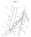
- FIG. 2 is an enlarged view around the external garnish 8 shown in FIG. 1 .
- An external surface S1 of the external garnish 8, an external surface S2 of the door garnish 9, and the external surface of the window glass 12 are parallel to one another, and are arranged on a substantially same plane, and the external surfaces S1, S2 of the external garnish 8 and the door garnish 9 are provided along a direction in which the window glass 12 extends- Since the external garnish 8, the door garnish 9, and the door sash where the window glass 12 is provided can be viewed as being integral, a stream-lined contour formed by those members can be clearly impressed.
- the external garnish 8 is made of resin, and has a base part 8a having the external surface S1, and a lip 8b closely contacting the fender panel 6 on a part of the upper side of the end of the external garnish 8.
- the lip 8b has an upper part arranged so as to face a part of the side of the A-pillar garnish 2. A space between the upper part of the lip 8b and the side of the A-pillar garnish 2 is prevented from being viewed as black according to this embodiment.
- a space formed between the lower end of the A-pillar garnish 2 and the fender panel 6 is sealed by the seal member 3, so as to be prevented from being viewed as black.
- the seal member 3 will be explained in more detail, and then an effect of preventing the space formed between the upper part of the lip 8b and the side of the A-pillar garnish 2 from being viewed as black will be explained.
- the upper end of the fender panel 6 is provided below the lower end of the A-pillar garnish 2.
- the seal member 3 is provided in order to seal the space between the end of the A-pillar garnish 2 and the end of the fender panel 6.
- the A-pillar garnish 2 is provided with a first extending portion 2b and a second extending portion 2c both extending in a direction from the lower end of the A-pillar garnish 2 toward the upper end of the fender panel 6.
- the fender panel 6 is provided with a flange 6a extending in a direction from the upper end of the fender panel 6 toward the lower end of the A-pillar garnish 2.
- the seal member 3 is mounted on and supported by the first extending portion 2b, the second extending portion 2c, the flange 6a, and the extending part 5a of the hinge cover 5.
- the width of the seal member 3 on a part of the first and second extending portions 2b, 2c is wider than the width of the seal member on a part of the flange 6a.
- the reason of this arrangement is the following.
- the A-pillar garnish 2 is made of resin and therefore the first and second extending portions 2b, 2c extending therefrom are also made of resin.
- the fender panel 6 is made of steel and therefore the flange 6a extending therefrom is also made of steel. Resin has a higher formability than that of steel. Therefore, a large extending portion can be easily formed.
- the hollow structure 2a extends from the main body of the A-pillar garnish 2 to the first extending portion 2b.
- the double-face tapes 18, 19, and 20 can be put on either one of the A-pillar garnish 2 and the seal member 3 at first, they are put on the seal-member-3 side at first in FIG. 7 .
- the double-face tapes 18, 19, and 20 are then put on the A-pillar garnish 2 at portions corresponding to respective leading ends of arrows.
- the double-face tape 18 is put on the exposed-surface-S side of the support member 3a, and put on the rear face of the main body of the A-pillar garnish 2 other than the first and second extending portions 2b, 2c.
- the double-face tape 19 is put on the rear-face side of the exposed surface S of the seal member 3, and put on the front surface of the first extending portion 2b of the A-pillar garnish 2.
- the double-face tape 20 is put on the side-face side of the seal member 3 successive from the exposed surface S, and put on the side face (upstanding face) of the second extending portion 2c of the A-pillar garnish 2.
- FIG. 8 shows the A-pillar garnish 2 to which the seal member 3 is attached. In FIG. 8 , those pieces are viewed from the front of the exposed surface S.
- the seal member 3 is mounted on the first and second extending portions 2b, 2c, and hung by the support member 3 a.
- FIG. 9 is a cross-sectional view along a line D-D in FIG. 3 .
- a side 2d of the A-pillar garnish 2 and the lip 8b of the external garnish 8 are arranged so as to face each other, thereby forming the merged part 21.
- the first shade 8c extending inwardly of the vehicle body I from the rear face of the external surface of the external garnish 8 can be seen through the space formed between the lip 8b and the side 2d of the A-pillar garnish 2 of the merged part 21.
- a second shade 8d is provided behind the first shade 8c.
- the second shade 8d also extends inwardly of the vehicle body 1 from the rear face of the external surface of the external garnish 8, but is longer than the first shade 8c in an inward direction from the vehicle body 1. Accordingly, the second shade 8d can be seen behind the first shade 8c through the space of the merged part 21. Since the first shade 8c and the second shade 8d can be seen through the merged part 21 (the space), it is possible to prevent the space from being viewed as black.
- the lip 8b, the first shade 8c, and the second shade 8d are supported by a lip base part 8e.
- the lip 8b, the first shade 8c, the second shade 8d, and the lip base part 8e are all made of resin, and are integrally formed by injection molding.
- the lip base part 8e is fixed to the base part 8a of the external garnish 8.
- the base part 8a forms the external surface S1 which has been explained with reference to FIG. 2 , and a door-facing side face 8f of the base part 8a faces the door 11.
- the lip 8b has a portion, which is not in the merged part 21, closely contacting the fender panel 6 as shown in FIG. 10 .
- the lip 8b is supported by the lip base part 8e, and the lip base part 8e is fixed to the base part 8a of the external garnish 8.
- the lip base part 8e is formed along the external surface of the fender panel 6.
- FIG. 11 is a top view showing the external garnish 8.
- the lip 8b is provided on the upper side of the external garnish 8 behind (rearwardly of) the base part 8a, the first shade 8c is provided behind the lip 8b, and the second shade 8d is provided behind the first shade 8c.
- the second shade 8d is joined with the door-facing side face 8f.
- FIG. 12 is a rear view showing the upper part of the external garnish 8.
- the door-facing side face 8f is formed by the base part 8a and the lip base part 8e, which are bonded so as to overlap with each other in the vicinity of the second shade 8d.
- the lip base part 8e forming the door-facing side face 8f and the second shade 8d are joined together on a side of the second shade 8d.
- the lip base part 8e is provided from the door-facing side face 8f along another side of the second shade 8d, the first shade 8c, and the lip 8b.
- the lip base part 8e, the second shade 8d, the first shade 8c, and the lip 8b are integrally formed by injection molding.
- a vehicle body structure for fitting a pillar garnish and a fender panel which surely prevents a space formed in the surface of a vehicle body from being viewed as black.
- the vehicle body structure includes a resin-made pillar garnish on a front surface side of a pillar of a vehicle body, a steel-made fender panel having an end on an end of the pillar garnish, and a seal member sealing a space between respective ends of the pillar garnish and the fender panel.
- the pillar garnish has an extending portion which extends in a direction from the end of the pillar garnish to the end of the fender panel.
- the fender panel has a flange which extends in a direction from the end of the fender panel to the end of the pillar garnish.
- the seal member is mounted on the extending portion and the flange.
Landscapes
- Engineering & Computer Science (AREA)
- Mechanical Engineering (AREA)
- Body Structure For Vehicles (AREA)
- Vehicle Interior And Exterior Ornaments, Soundproofing, And Insulation (AREA)
Abstract
Description
- The present application claims priority under 35 USC 119 to Japanese Patent Application No.
2009-239954 filed on October 19, 2009 - The present invention relates to a vehicle body structure for fitting a pillar garnish and a fender panel to a vehicle body.
- According to conventional vehicle body structures, a pillar garnish (an A-pillar garnish) has, at both sides thereof, one side being smoothly merged with a window panel, and another side being also smoothly merged with a window glass. Also, the A-pillar garnish has a lower end smoothly merged with a fender panel. Accordingly, a stream-lined contour of a vehicle body is formed. There is proposed a technology related to fitting of an A-pillar garnish to a fender panel (see, for example,
JP 2000-177506 A - As the pillar garnish is smoothly merged with the window panel at one side of the pillar garnish, the fender panel is also smoothly merged with a front hood on one side of the fender panel. In a design which gives priority to the fitting of the fender panel to the front hood, a space may be formed between the fender panel and the bottom of the A-pillar garnish in some cases. Such a space is not desirable for a vehicle body with a stream-lined contour because it is viewed as black through human eyes, and gets attention. The blackness of the space can be suppressed by sealing the space by a seal member. However, it is necessary to surely hold the seal member so that the seal member does not fall in the space.
- Moreover, when a design of an external garnish fitting to the shape of the edge of the window glass is prioritized, a space may be formed between the external garnish and the pillar garnish. As in the case of the foregoing space, this space is also viewed as black through human eyes and easily gets attention. This is not desirable for the vehicle body with a stream-lined contour. The reason why the space is viewed as black is that no light entering in the space comes out from that space at all. If a shade which reflects incoming light is provided right below the space, reflected light from the shade can prevent such a space from being viewed as black. However, as in the case of the foregoing seal member, it is necessary to surely hold the shade so that the shade does not fall in the space.
- An object of the present invention is to provide a vehicle body structure for fitting a pillar garnish and a fender panel which can surely prevent a space formed in a surface of a vehicle body from being viewed as black.
- In order to achieve the above object, a first aspect of the present invention provides a vehicle body structure for fitting a pillar garnish and a fender panel, and the vehicle body structure includes: a pillar garnish which is made of resin and which is provided on a front surface side of a pillar of a vehicle body; a fender panel which is made of steel and which has an end provided on an end of the pillar garnish; and a seal member which seals a space between respective ends of the pillar garnish and the fender panel, in which the pillar garnish is provided with an extending portion which extends in a direction from the end of the pillar garnish to the end of the fender panel, the fender panel is provided with a flange which extends in a direction from the end of the fender panel to the end of the pillar garnish, and the seal member is mounted on the extending portion and the flange.
- According to this aspect, a space formed between the pillar garnish and the fender panel is sealed by the seal member. Accordingly, it is possible to prevent such a space from being viewed as black. Also, the seal member is mounted on the flange extending from the fender panel and the extending portion extending from the pillar garnish. Accordingly, the seal member is supported from both sides of the space, thereby enhancing the retaining strength of the seal member. That is, even if the width of the space is large, the seal member supported from both sides of the space is stably and surely retained, and can be retained regardless of the shape of the space.
- Preferably, a second aspect of the present invention provides the vehicle body structure of the present invention, in which the width of a portion of the space where the extending portion is provided is wider than the width of a portion of the space where the flange is provided. According to this aspect, even if the space has a shape with a different width depending on a location, the extending portion of the pillar garnish made of resin having a high formability is enlarged according to the width of a wide portion and is provided at the wide portion, and thereby an area sufficient for mounting the seal member can be secured even in the wide portion.
- Preferably, a third aspect of the present invention provides the vehicle body structure of the present invention, in which the extending portion has a hollow structure. According to this aspect, the strength of the extending portion can be enhanced, and the seal member can be surely retained. Also, since the pillar garnish is made of resin, the hollow structure can be easily formed in the extending portion of the pillar garnish.
- A fourth aspect of the present invention provides the vehicle body structure of the present invention, further including a hinge cover which covers a hinge that supports a front hood to be openable, and the seal member is mounted continuously from the hinge cover in a direction in which the hinge cover extends.
- According to this aspect, the seal member for sealing the space can be seen as an integral piece with the hinge cover, the seal member does not stand out, thereby improving the design characteristics.
- A fifth aspect of the present invention provides the vehicle body structure of the present invention, further including an external garnish which is made of resin and which is arranged adjacent to the fender panel and the pillar garnish, and the external garnish is provided with a shade which is formed by injection molding in a merged part that faces the pillar garnish, and which extends inwardly of the vehicle body from a rear face of an external surface of the external garnish.
- According to this aspect, in order to conform the shape to the fender panel made of steel, the space (merged part) formed between the external garnish made of resin and the pillar garnish may be large. Even in such a case, it is possible to prevent such a space from being viewed as black by the shade extending inwardly of the vehicle body from the rear face of the external surface of the external garnish. This is because the shade is arranged at a position where the shade can be seen through the space, light entering from the space illuminates the shade, and reflected light from the shade prevents the space from being viewed as black. Also, the shade is formed by injection molding, and thereby it can be surely retained.
- According to the present invention, a vehicle body structure for fitting a pillar garnish and a fender panel is provided which can surely prevent a space formed in a surface of a vehicle body from being viewed as black.
-
-
FIG. 1 is a perspective view showing a part of a vehicle body including a vehicle body structure for fitting a pillar garnish and a fender panel according to an embodiment of the present invention; -
FIG. 2 is an enlarged view around an external garnish shown inFIG. 1 ; -
FIG. 3 is an enlarged view around a seal member in the vicinity of the external garnish shown inFIG. 2 ; -
FIG. 4 is a cross-sectional view along a line A-A inFIG. 3 ; -
FIG. 5 is a cross-sectional view along a line B-B inFIG. 3 ; -
FIG. 6 is a cross-sectional view along a line C-C inFIG. 3 ; -
FIG. 7 is a diagram showing how to attach the seal member to an A-pillar garnish; -
FIG. 8 is a perspective view of the A-pillar garnish to which the seal member is attached; -
FIG. 9 is a cross-sectional view along a line D-D inFIG. 3 ; -
FIG. 10 is a cross-sectional view along a line E-E inFIG. 3 ; -
FIG. 11 is a top view of the external garnish; and -
FIG. 12 is a rear view showing a top part of the external garnish. - A detailed explanation will be given of an embodiment of the present invention with reference to the accompanying drawings accordingly. The same structural element will be denoted by the same reference numeral through the whole drawings, and the duplicated explanation will be omitted below.
-
FIG. 1 shows avehicle body 1 having a vehicle body structure for fitting a pillar garnish and a fender panel according to the embodiment of the present invention. In thevehicle body 1, a stream-lined contour is formed from awindow panel 7 to afront hood 4. Ahinge cover 5 is provided across both sides of the vehicle body, and covers a hinge (not shown) that supports thefront hood 4 to be openable, In order to protect respective A-pillars (not shown) made of steel, resin-made A-pillargarnishes 2 are provided on the surface of respective A-pillars at both sides of thewindow panel 7. Each A-pillargarnish 2 has an external surface having one side smoothly merged with an external surface of thewindow panel 7, and another side smoothly merged with a door sash where awindow glass 12 of adoor 11 is provided. Also, provided between a lower end of theA-pillar garnish 2 and afender panel 6 is aseal member 3, and theA-pillar garnish 2 has the lower end where the external surface of theA-pillar garnish 2 is smoothly merged with thefender panel 6 made of steel through theseal member 3. Theseal member 3 is arranged continuously to thehinge cover 5 in a direction in which thehinge cover 5 extends. Accordingly, a strearn-lined contour from theA-pillar garnish 2 to thefender panel 6 is formed. Thefender panels 6 are provided at both sides of thefront hood 4, and eachfender panel 6 and thefront hood 4 have respective external surfaces smoothly merged with each other. - In order to also give a stream-lined contour to the
window glass 12 arranged along theA-pillar garnish 2, adoor garnish 9 where aside mirror 10 is provided, and anexternal garnish 8 are provided in a traveling direction of thevehicle body 1 from thewindow glass 12. Individual edges of the door sash where thewindow glass 12 is provided, thedoor garnish 9, and of theexternal garnish 8 are formed continuously to produce a stream-lined contour. Thedoor garnish 9 is fixed to thedoor 11, and theexternal garnish 8 is fixed to an outer panel of thevehicle body 1. -
FIG. 2 is an enlarged view around theexternal garnish 8 shown inFIG. 1 . An external surface S1 of theexternal garnish 8, an external surface S2 of thedoor garnish 9, and the external surface of thewindow glass 12 are parallel to one another, and are arranged on a substantially same plane, and the external surfaces S1, S2 of theexternal garnish 8 and thedoor garnish 9 are provided along a direction in which thewindow glass 12 extends- Since theexternal garnish 8, thedoor garnish 9, and the door sash where thewindow glass 12 is provided can be viewed as being integral, a stream-lined contour formed by those members can be clearly impressed. Theexternal garnish 8 is made of resin, and has abase part 8a having the external surface S1, and alip 8b closely contacting thefender panel 6 on a part of the upper side of the end of theexternal garnish 8. Thelip 8b has an upper part arranged so as to face a part of the side of theA-pillar garnish 2. A space between the upper part of thelip 8b and the side of theA-pillar garnish 2 is prevented from being viewed as black according to this embodiment. - Also, according to this embodiment, a space formed between the lower end of the
A-pillar garnish 2 and thefender panel 6 is sealed by theseal member 3, so as to be prevented from being viewed as black. In the following explanation, first, theseal member 3 will be explained in more detail, and then an effect of preventing the space formed between the upper part of thelip 8b and the side of theA-pillar garnish 2 from being viewed as black will be explained. -
FIG. 3 is an enlarged view around theseal member 3 shown inFIG. 2 . Theseal member 3 is arranged continuously from thehinge cover 5 in a direction in which thehinge cover 5 extends. An extendingpart 5a of thehinge cover 5 is thinner than portions other than the extendingpart 5a of thehinge cover 5, and theseal member 3 is mounted so as to overlap the upper side (external side) of the thin extendingpart 5a, thereby supporting theseal member 3. Also, as theseal member 3 is mounted on the upper side (external side) of the thin extendingpart 5a, theseal member 3 is designed so as to have a thickness substantially equal to the thickness of a portion of thehinge cover 5 other than the extendingpart 5a. According to this structure, since theseal member 3 and thehinge cover 5 can be seen as an integral piece, theseal member 3 does not stand out, thereby improving the design characteristics. - The upper end of the
fender panel 6 is provided below the lower end of theA-pillar garnish 2. Theseal member 3 is provided in order to seal the space between the end of theA-pillar garnish 2 and the end of thefender panel 6. - The
A-pillar garnish 2 is provided with a first extendingportion 2b and a second extendingportion 2c both extending in a direction from the lower end of theA-pillar garnish 2 toward the upper end of thefender panel 6. Thefender panel 6 is provided with aflange 6a extending in a direction from the upper end of thefender panel 6 toward the lower end of theA-pillar garnish 2. Theseal member 3 is mounted on and supported by the first extendingportion 2b, the second extendingportion 2c, theflange 6a, and the extendingpart 5a of thehinge cover 5. - The
seal member 3 seals the space formed between theA-pillar garnish 2 and thefender panel 6 so as to prevent such a space from being viewed as black, and an exposed surface S of theseal member 3 gives the smooth merging of respective external surfaces from theA-pillar garnish 2 to thefender panel 6. Since theseal member 3 is mounted on theflange 6a extending from thefender panel 6 and on the first and second extendingportions A-pillar garnish 2, theseal member 3 is supported from both sides thereof. Since theseal member 3 is mounted on theflange 6a extending from thefender panel 6 and on the extendingpart 5a of thehinge cover 5, theseal member 3 is supported from both ends thereof. Also, asupport 3a extends from theseal member 3 to the rear surface of theA-pillar garnish 2. Thesupport 3a is integrated with the main body of theseal member 3, and is fixed to the rear surface of theA-pillar garnish 2. Thesupport 3a hangs up the main body of theseal member 3 so as not to be detached. Accordingly, the retained strength of theseal member 3 is enhanced. - The width of the
seal member 3 on a part of the first and second extendingportions flange 6a. The reason of this arrangement is the following. TheA-pillar garnish 2 is made of resin and therefore the first and second extendingportions fender panel 6 is made of steel and therefore theflange 6a extending therefrom is also made of steel. Resin has a higher formability than that of steel. Therefore, a large extending portion can be easily formed. - Note that it will be discussed later but the side of the
A-pillar garnish 2 and thelip 8b of theexternal garnish 8 are arranged so as to face each other, thereby forming amerged part 21. Afirst shade 8c extending inwardly of thevehicle body 1 from the rear face of the external surface of theexternal garnish 8 can be seen through a space between thelip 8b and the side of theA-pillar garnish 2 of themerged part 21. Accordingly, it is possible to prevent the space from being viewed as black. -
FIG. 4 is a cross-sectional view along a line A-A inFIG. 3 . Thewindow panel 7 is supported by apillar 13 through amolding 16, and is fixed thereto by means of abond 17. TheA-pillar garnish 2 is supported by thepillar 13 through asupport member 14 such as a clip. Aseal member 15 is provided on thepillar 13 and the lip of themolding 16 extending on thepillar 13. TheA-pillar garnish 2 is provided with ahollow structure 2a that passes all the way through from the upper end of theA-pillar garnish 2 to the lower end thereof along the vertical (lengthwise) direction. Thehollow structure 2a enhances the strength of theA-pillar garnish 2. - The
support 3a of theseal member 3 is bonded and fixed on the rear face of the external surface of the lower end of theA-pillar garnish 2 using a double-face tape 18. Theseal member 3 is so formed as to be integral from thesupport 3a on the rear side of theA-pillar garnish 2 to thelip 3b that runs onto the front surface of theflange 6a of thefender panel 6. The external surface of thelip 3b corresponds to a part of the exposed surface S shown inFIG. 3 . Thelip 3b of theseal member 3 is supported by theflange 6a from underneath, and is hung by thesupport 3 a. Thereby, theseal member 3 can be surely supported. Note that thelip 8b of theexternal garnish 8 closely contacts thefender panel 6. -
FIG. 5 is a cross-sectional view along a line B-B inFIG. 3 . Theseal member 3 is bonded and fixed on the first extendingportion 2b of theA-pillar garnish 2 using a double-face tape 19. The foregoinghollow structure 2a extends in the first extendingportion 2b. Thehollow structure 2a can enhance the strength of the first extendingportion 2b, and the joining strength between the first extendingportion 2b and the main body of theA-pillar garnish 2, thereby surely retaining theseal member 3. Also, since theA-pillar garnish 2 is made of resin, a hollow structure can be easily formed in the first extendingportion 2b which is made of resin and which is integrally formed with theA-pillar garnish 2. -
FIG. 6 is a cross-sectional view along a line C-C inFIG. 3 . Theseal member 3 is bonded and fixed on the second extendingportion 2c of theA-pillar garnish 2 using a double-face tape 20. Also, theseal member 3 is supported by the extendingpart 5a of thehinge cover 5 from underneath. Accordingly, theseal member 3 is surely retained. - Next, with reference to
FIG. 7 , an explanation will be given of how to attach theseal member 3 to theA-pillar garnish 2. Thehollow structure 2a extends from the main body of theA-pillar garnish 2 to the first extendingportion 2b. Although the double-face tapes A-pillar garnish 2 and theseal member 3 at first, they are put on the seal-member-3 side at first inFIG. 7 . The double-face tapes A-pillar garnish 2 at portions corresponding to respective leading ends of arrows. The double-face tape 18 is put on the exposed-surface-S side of thesupport member 3a, and put on the rear face of the main body of theA-pillar garnish 2 other than the first and second extendingportions face tape 19 is put on the rear-face side of the exposed surface S of theseal member 3, and put on the front surface of the first extendingportion 2b of theA-pillar garnish 2. The double-face tape 20 is put on the side-face side of theseal member 3 successive from the exposed surface S, and put on the side face (upstanding face) of the second extendingportion 2c of theA-pillar garnish 2.
FIG. 8 shows theA-pillar garnish 2 to which theseal member 3 is attached. InFIG. 8 , those pieces are viewed from the front of the exposed surface S. As is clear from this figure, theseal member 3 is mounted on the first and second extendingportions support member 3 a. - Next, an explanation will be given of an effect of preventing the space formed between the upper part of the
lip 8b of theexternal garnish 8 and the side of theA-pillar garnish 2 from being viewed as black which has been explained with reference toFIG. 3 . -
FIG. 9 is a cross-sectional view along a line D-D inFIG. 3 . Aside 2d of theA-pillar garnish 2 and thelip 8b of theexternal garnish 8 are arranged so as to face each other, thereby forming themerged part 21. Thefirst shade 8c extending inwardly of the vehicle body I from the rear face of the external surface of theexternal garnish 8 can be seen through the space formed between thelip 8b and theside 2d of theA-pillar garnish 2 of themerged part 21. Also, relative to thelip 8b (the merged part 21), asecond shade 8d is provided behind thefirst shade 8c. Thesecond shade 8d also extends inwardly of thevehicle body 1 from the rear face of the external surface of theexternal garnish 8, but is longer than thefirst shade 8c in an inward direction from thevehicle body 1. Accordingly, thesecond shade 8d can be seen behind thefirst shade 8c through the space of themerged part 21. Since thefirst shade 8c and thesecond shade 8d can be seen through the merged part 21 (the space), it is possible to prevent the space from being viewed as black. - The
lip 8b, thefirst shade 8c, and thesecond shade 8d are supported by alip base part 8e. Thelip 8b, thefirst shade 8c, thesecond shade 8d, and thelip base part 8e are all made of resin, and are integrally formed by injection molding. Thelip base part 8e is fixed to thebase part 8a of theexternal garnish 8. Thebase part 8a forms the external surface S1 which has been explained with reference toFIG. 2 , and a door-facingside face 8f of thebase part 8a faces thedoor 11. Thelip 8b has a portion, which is not in themerged part 21, closely contacting thefender panel 6 as shown inFIG. 10 . Thelip 8b is supported by thelip base part 8e, and thelip base part 8e is fixed to thebase part 8a of theexternal garnish 8. Thelip base part 8e is formed along the external surface of thefender panel 6. -
FIG. 11 is a top view showing theexternal garnish 8. Thelip 8b is provided on the upper side of theexternal garnish 8 behind (rearwardly of) thebase part 8a, thefirst shade 8c is provided behind thelip 8b, and thesecond shade 8d is provided behind thefirst shade 8c. Thesecond shade 8d is joined with the door-facingside face 8f. -
FIG. 12 is a rear view showing the upper part of theexternal garnish 8. The door-facingside face 8f is formed by thebase part 8a and thelip base part 8e, which are bonded so as to overlap with each other in the vicinity of thesecond shade 8d. Thelip base part 8e forming the door-facingside face 8f and thesecond shade 8d are joined together on a side of thesecond shade 8d. Thelip base part 8e is provided from the door-facingside face 8f along another side of thesecond shade 8d, thefirst shade 8c, and thelip 8b. Thelip base part 8e, thesecond shade 8d, thefirst shade 8c, and thelip 8b are integrally formed by injection molding.
When thefirst shade 8c is extended and elongated inwardly of thevehicle body 1 so as to abut theside 2d of theA-pillar garnish 2 or when thesecond shade 8d is extended and elongated inwardly of thevehicle body 1 so as to abut thepillar 13, it is possible to further prevent the space of themerged part 21 from being viewed as black. - A vehicle body structure for fitting a pillar garnish and a fender panel is provided which surely prevents a space formed in the surface of a vehicle body from being viewed as black. The vehicle body structure includes a resin-made pillar garnish on a front surface side of a pillar of a vehicle body, a steel-made fender panel having an end on an end of the pillar garnish, and a seal member sealing a space between respective ends of the pillar garnish and the fender panel. The pillar garnish has an extending portion which extends in a direction from the end of the pillar garnish to the end of the fender panel. The fender panel has a flange which extends in a direction from the end of the fender panel to the end of the pillar garnish. The seal member is mounted on the extending portion and the flange.
Claims (5)
- A vehicle body structure for fitting a pillar garnish and a fender panel, comprising:a pillar garnish which is made of resin and which is provided on a front surface side of a pillar of a vehicle body;a fender panel which is made of steel and which has an end provided on an end of the pillar garnish; anda seal member which seals a space between respective ends of the pillar garnish and the fender panel, whereinthe pillar garnish is provided with an extending portion which extends in a direction from the end of the pillar garnish to the end of the fender panel,the fender panel is provided with a flange which extends in a direction from the end of the fender panel to the end of the pillar garnish, andthe seal member is mounted on the extending portion and the flange.
- The vehicle body structure according to claim 1, wherein a width of a portion of the space where the extending portion is provided is wider than a width of a portion of the space where the flange is provided.
- The vehicle body structure according to claim 1 or 2, wherein the extending portion has a hollow structure.
- The vehicle body structure according to any one of claims 1-3, further comprising a hinge cover which covers a hinge that supports a front hood to be openable,
wherein the seal member is mounted continuously from the hinge cover in a direction in which the hinge cover extends. - The vehicle body structure according to any one of claims 1-4, further comprising an external garnish which is made of resin and which is arranged adjacent to the fender panel and the pillar garnish,
wherein the external garnish is provided with a shade which is formed by injection molding in a merged part that faces the pillar garnish, and which extends inwardly of the vehicle body from a rear face of an external surface of the external garnish.
Applications Claiming Priority (1)
| Application Number | Priority Date | Filing Date | Title |
|---|---|---|---|
| JP2009239954A JP4996665B2 (en) | 2009-10-19 | 2009-10-19 | Body structure of pillar garnish and fender panel |
Publications (3)
| Publication Number | Publication Date |
|---|---|
| EP2311690A2 true EP2311690A2 (en) | 2011-04-20 |
| EP2311690A3 EP2311690A3 (en) | 2012-10-10 |
| EP2311690B1 EP2311690B1 (en) | 2013-02-20 |
Family
ID=43302972
Family Applications (1)
| Application Number | Title | Priority Date | Filing Date |
|---|---|---|---|
| EP10188093A Not-in-force EP2311690B1 (en) | 2009-10-19 | 2010-10-19 | Vehicle body structure for fitting pillar garnish and fender panel |
Country Status (4)
| Country | Link |
|---|---|
| US (1) | US8348321B2 (en) |
| EP (1) | EP2311690B1 (en) |
| JP (1) | JP4996665B2 (en) |
| CN (1) | CN102039855B (en) |
Cited By (1)
| Publication number | Priority date | Publication date | Assignee | Title |
|---|---|---|---|---|
| EP3524495A1 (en) * | 2018-02-08 | 2019-08-14 | Toyota Jidosha Kabushiki Kaisha | Pillar structure |
Families Citing this family (12)
| Publication number | Priority date | Publication date | Assignee | Title |
|---|---|---|---|---|
| JP4996665B2 (en) * | 2009-10-19 | 2012-08-08 | 本田技研工業株式会社 | Body structure of pillar garnish and fender panel |
| FR2965771B1 (en) * | 2010-10-12 | 2012-12-28 | Faurecia Bloc Avant | FRONT OR REAR ASSEMBLY OF A MOTOR VEHICLE COMPRISING A FIXING ELEMENT FOR FIXING ELEMENTS TO THE VEHICLE BODY |
| JP5994568B2 (en) * | 2012-10-26 | 2016-09-21 | マツダ株式会社 | Car side structure |
| BR112015033048B1 (en) * | 2013-07-03 | 2021-12-07 | Honda Motor Co., Ltd | DECORATIVE STRUCTURE FOR VEHICLE |
| DE102015004413A1 (en) * | 2015-04-02 | 2016-10-06 | GM Global Technology Operations LLC (n. d. Ges. d. Staates Delaware) | vehicle body |
| DE102015005895A1 (en) * | 2015-05-08 | 2016-11-10 | GM Global Technology Operations LLC (n. d. Ges. d. Staates Delaware) | Motor vehicle body with packing |
| US9738318B2 (en) * | 2016-01-08 | 2017-08-22 | Honda Motor Co., Ltd. | Vehicle frame assembly |
| DE102016114353A1 (en) * | 2016-08-03 | 2018-02-08 | Daimler Ag | End cap for an illuminated trim strip arrangement and trim strip arrangement |
| US10703178B2 (en) * | 2016-11-07 | 2020-07-07 | Ford Global Technologies, Llc | Windshield wrapped vehicle pillar |
| DE102016015675A1 (en) | 2016-12-23 | 2018-06-28 | GM Global Technology Operations LLC (n. d. Ges. d. Staates Delaware) | vehicle body |
| US11511610B2 (en) | 2018-11-12 | 2022-11-29 | Shape Corp. | Vehicle door carrier with integrated edge seal and method of manufacture |
| KR20250014925A (en) * | 2023-07-24 | 2025-02-03 | 현대자동차주식회사 | Structure for Quadrant Cover |
Citations (2)
| Publication number | Priority date | Publication date | Assignee | Title |
|---|---|---|---|---|
| JP2000177506A (en) | 1998-12-21 | 2000-06-27 | Nissan Motor Co Ltd | Car front side molding mounting structure |
| JP2009239954A (en) | 2009-07-06 | 2009-10-15 | Advantest Corp | Cycle shift detection device between serial data |
Family Cites Families (20)
| Publication number | Priority date | Publication date | Assignee | Title |
|---|---|---|---|---|
| JPH0620812B2 (en) * | 1985-09-20 | 1994-03-23 | 日産自動車株式会社 | Structure of the front window glass mole and front wing mating part in automobiles |
| JP3413284B2 (en) * | 1994-07-07 | 2003-06-03 | 本田技研工業株式会社 | Front fender reinforcement structure |
| JP2001074011A (en) * | 1999-09-02 | 2001-03-23 | Honda Motor Co Ltd | Joint fastening structure of members |
| JP3299230B2 (en) * | 1999-09-03 | 2002-07-08 | 本田技研工業株式会社 | Pillar garnish mounting structure |
| JP3974097B2 (en) | 2003-10-16 | 2007-09-12 | 本田技研工業株式会社 | Cowl top garnish structure |
| JP3845093B2 (en) * | 2004-01-22 | 2006-11-15 | 東海興業株式会社 | Front pillar garnish |
| JP4405327B2 (en) * | 2004-06-30 | 2010-01-27 | 本田技研工業株式会社 | Front fender structure |
| JP4260159B2 (en) * | 2005-11-28 | 2009-04-30 | トヨタ車体株式会社 | Mounting structure of vehicle pillar garnish |
| JP4923724B2 (en) * | 2006-05-18 | 2012-04-25 | マツダ株式会社 | Body structure |
| US7651158B2 (en) * | 2006-05-10 | 2010-01-26 | Mazda Motor Corporation | Vehicle body structure |
| JP4226622B2 (en) * | 2006-09-27 | 2009-02-18 | 本田技研工業株式会社 | Vehicle garnish mounting structure |
| JP4778936B2 (en) * | 2007-06-22 | 2011-09-21 | 株式会社豊田自動織機 | Pillar structure in automobile |
| JP4450064B2 (en) * | 2007-12-17 | 2010-04-14 | 日産自動車株式会社 | Fender protector structure |
| JP4500858B2 (en) * | 2008-02-29 | 2010-07-14 | 本田技研工業株式会社 | Resin garnish mounting structure |
| JP5029499B2 (en) * | 2008-06-10 | 2012-09-19 | トヨタ車体株式会社 | Fender panel fixing structure for passenger cars |
| US7980613B2 (en) * | 2008-08-07 | 2011-07-19 | Honda Motor Co., Ltd. | Rear garnish clip |
| US8408622B2 (en) * | 2008-09-19 | 2013-04-02 | Aisin Seiki Kabushiki Kaisha | Frame molding |
| US7841636B2 (en) * | 2009-02-02 | 2010-11-30 | Honda Motor Co., Ltd. | Garnish seal and assembly for a vehicle |
| JP4996665B2 (en) * | 2009-10-19 | 2012-08-08 | 本田技研工業株式会社 | Body structure of pillar garnish and fender panel |
| FR2956068B1 (en) * | 2010-02-08 | 2012-04-20 | Hutchinson | EXTERIOR COVER FOR AUTOMOTIVE VEHICLE DOOR FRAME, AND INCORPORATING SEALING MODULE |
-
2009
- 2009-10-19 JP JP2009239954A patent/JP4996665B2/en not_active Expired - Fee Related
-
2010
- 2010-10-09 CN CN201010503431.1A patent/CN102039855B/en not_active Expired - Fee Related
- 2010-10-18 US US12/906,297 patent/US8348321B2/en not_active Expired - Fee Related
- 2010-10-19 EP EP10188093A patent/EP2311690B1/en not_active Not-in-force
Patent Citations (2)
| Publication number | Priority date | Publication date | Assignee | Title |
|---|---|---|---|---|
| JP2000177506A (en) | 1998-12-21 | 2000-06-27 | Nissan Motor Co Ltd | Car front side molding mounting structure |
| JP2009239954A (en) | 2009-07-06 | 2009-10-15 | Advantest Corp | Cycle shift detection device between serial data |
Cited By (1)
| Publication number | Priority date | Publication date | Assignee | Title |
|---|---|---|---|---|
| EP3524495A1 (en) * | 2018-02-08 | 2019-08-14 | Toyota Jidosha Kabushiki Kaisha | Pillar structure |
Also Published As
| Publication number | Publication date |
|---|---|
| US20110089719A1 (en) | 2011-04-21 |
| US8348321B2 (en) | 2013-01-08 |
| CN102039855A (en) | 2011-05-04 |
| EP2311690B1 (en) | 2013-02-20 |
| JP4996665B2 (en) | 2012-08-08 |
| JP2011084226A (en) | 2011-04-28 |
| CN102039855B (en) | 2013-06-19 |
| EP2311690A3 (en) | 2012-10-10 |
Similar Documents
| Publication | Publication Date | Title |
|---|---|---|
| EP2311690B1 (en) | Vehicle body structure for fitting pillar garnish and fender panel | |
| CN101622145B (en) | car door | |
| CN100509492C (en) | Structure for attaching interior trim panel around automotive front pillar | |
| CN101578217B (en) | car pillar structure | |
| US7651158B2 (en) | Vehicle body structure | |
| US10150512B2 (en) | Automobile pillar structure | |
| CN108725159A (en) | Vehicle sealing strip | |
| US10086876B2 (en) | Motor vehicle body | |
| CN104602932B (en) | car door | |
| MXPA06011574A (en) | One-piece plastic retainer with integrated water management feature. | |
| CN104010924A (en) | body side structure | |
| CN101132940A (en) | Vehicle glass guide structure | |
| KR20100039338A (en) | Arrangement for fastening a motor vehicle body surface liner in the vicinity of a window glass | |
| JP6083750B2 (en) | Car mirror mounting structure | |
| KR20250124634A (en) | Roof side rail for vehicle | |
| US11731494B2 (en) | Vehicle door assembly | |
| JP2008285057A (en) | Fixed window structure of automobile | |
| CN205736838U (en) | Motor vehicles tail-gate | |
| JP5948137B2 (en) | Vehicle door frame | |
| US20210188055A1 (en) | Fixed window for vehicle | |
| JP2600442B2 (en) | Peripheral structure of window panel | |
| JP2021160443A (en) | Vehicular glass module and attachment member | |
| CN105539096A (en) | Guide rail cover structure for sliding door | |
| JP4300860B2 (en) | Automotive back door seal structure | |
| JP5659528B2 (en) | Windshield structure of vehicle |
Legal Events
| Date | Code | Title | Description |
|---|---|---|---|
| PUAI | Public reference made under article 153(3) epc to a published international application that has entered the european phase |
Free format text: ORIGINAL CODE: 0009012 |
|
| 17P | Request for examination filed |
Effective date: 20101019 |
|
| AK | Designated contracting states |
Kind code of ref document: A2 Designated state(s): AL AT BE BG CH CY CZ DE DK EE ES FI FR GB GR HR HU IE IS IT LI LT LU LV MC MK MT NL NO PL PT RO RS SE SI SK SM TR |
|
| AX | Request for extension of the european patent |
Extension state: BA ME |
|
| RIC1 | Information provided on ipc code assigned before grant |
Ipc: B60R 13/04 20060101AFI20120518BHEP Ipc: B60R 13/06 20060101ALI20120518BHEP |
|
| PUAL | Search report despatched |
Free format text: ORIGINAL CODE: 0009013 |
|
| AK | Designated contracting states |
Kind code of ref document: A3 Designated state(s): AL AT BE BG CH CY CZ DE DK EE ES FI FR GB GR HR HU IE IS IT LI LT LU LV MC MK MT NL NO PL PT RO RS SE SI SK SM TR |
|
| AX | Request for extension of the european patent |
Extension state: BA ME |
|
| RIC1 | Information provided on ipc code assigned before grant |
Ipc: B60R 13/06 20060101ALI20120904BHEP Ipc: B60R 13/04 20060101AFI20120904BHEP |
|
| GRAP | Despatch of communication of intention to grant a patent |
Free format text: ORIGINAL CODE: EPIDOSNIGR1 |
|
| GRAS | Grant fee paid |
Free format text: ORIGINAL CODE: EPIDOSNIGR3 |
|
| GRAA | (expected) grant |
Free format text: ORIGINAL CODE: 0009210 |
|
| AK | Designated contracting states |
Kind code of ref document: B1 Designated state(s): AL AT BE BG CH CY CZ DE DK EE ES FI FR GB GR HR HU IE IS IT LI LT LU LV MC MK MT NL NO PL PT RO RS SE SI SK SM TR |
|
| REG | Reference to a national code |
Ref country code: GB Ref legal event code: FG4D |
|
| REG | Reference to a national code |
Ref country code: CH Ref legal event code: EP |
|
| REG | Reference to a national code |
Ref country code: AT Ref legal event code: REF Ref document number: 597397 Country of ref document: AT Kind code of ref document: T Effective date: 20130315 |
|
| REG | Reference to a national code |
Ref country code: IE Ref legal event code: FG4D |
|
| REG | Reference to a national code |
Ref country code: DE Ref legal event code: R096 Ref document number: 602010005082 Country of ref document: DE Effective date: 20130411 |
|
| REG | Reference to a national code |
Ref country code: AT Ref legal event code: MK05 Ref document number: 597397 Country of ref document: AT Kind code of ref document: T Effective date: 20130220 |
|
| REG | Reference to a national code |
Ref country code: NL Ref legal event code: VDEP Effective date: 20130220 |
|
| REG | Reference to a national code |
Ref country code: LT Ref legal event code: MG4D |
|
| PG25 | Lapsed in a contracting state [announced via postgrant information from national office to epo] |
Ref country code: AT Free format text: LAPSE BECAUSE OF FAILURE TO SUBMIT A TRANSLATION OF THE DESCRIPTION OR TO PAY THE FEE WITHIN THE PRESCRIBED TIME-LIMIT Effective date: 20130220 Ref country code: ES Free format text: LAPSE BECAUSE OF FAILURE TO SUBMIT A TRANSLATION OF THE DESCRIPTION OR TO PAY THE FEE WITHIN THE PRESCRIBED TIME-LIMIT Effective date: 20130531 Ref country code: IS Free format text: LAPSE BECAUSE OF FAILURE TO SUBMIT A TRANSLATION OF THE DESCRIPTION OR TO PAY THE FEE WITHIN THE PRESCRIBED TIME-LIMIT Effective date: 20130620 Ref country code: LT Free format text: LAPSE BECAUSE OF FAILURE TO SUBMIT A TRANSLATION OF THE DESCRIPTION OR TO PAY THE FEE WITHIN THE PRESCRIBED TIME-LIMIT Effective date: 20130220 Ref country code: SE Free format text: LAPSE BECAUSE OF FAILURE TO SUBMIT A TRANSLATION OF THE DESCRIPTION OR TO PAY THE FEE WITHIN THE PRESCRIBED TIME-LIMIT Effective date: 20130220 Ref country code: NO Free format text: LAPSE BECAUSE OF FAILURE TO SUBMIT A TRANSLATION OF THE DESCRIPTION OR TO PAY THE FEE WITHIN THE PRESCRIBED TIME-LIMIT Effective date: 20130520 Ref country code: BG Free format text: LAPSE BECAUSE OF FAILURE TO SUBMIT A TRANSLATION OF THE DESCRIPTION OR TO PAY THE FEE WITHIN THE PRESCRIBED TIME-LIMIT Effective date: 20130520 |
|
| PG25 | Lapsed in a contracting state [announced via postgrant information from national office to epo] |
Ref country code: LV Free format text: LAPSE BECAUSE OF FAILURE TO SUBMIT A TRANSLATION OF THE DESCRIPTION OR TO PAY THE FEE WITHIN THE PRESCRIBED TIME-LIMIT Effective date: 20130220 Ref country code: FI Free format text: LAPSE BECAUSE OF FAILURE TO SUBMIT A TRANSLATION OF THE DESCRIPTION OR TO PAY THE FEE WITHIN THE PRESCRIBED TIME-LIMIT Effective date: 20130220 Ref country code: BE Free format text: LAPSE BECAUSE OF FAILURE TO SUBMIT A TRANSLATION OF THE DESCRIPTION OR TO PAY THE FEE WITHIN THE PRESCRIBED TIME-LIMIT Effective date: 20130220 Ref country code: PT Free format text: LAPSE BECAUSE OF FAILURE TO SUBMIT A TRANSLATION OF THE DESCRIPTION OR TO PAY THE FEE WITHIN THE PRESCRIBED TIME-LIMIT Effective date: 20130620 Ref country code: PL Free format text: LAPSE BECAUSE OF FAILURE TO SUBMIT A TRANSLATION OF THE DESCRIPTION OR TO PAY THE FEE WITHIN THE PRESCRIBED TIME-LIMIT Effective date: 20130220 Ref country code: GR Free format text: LAPSE BECAUSE OF FAILURE TO SUBMIT A TRANSLATION OF THE DESCRIPTION OR TO PAY THE FEE WITHIN THE PRESCRIBED TIME-LIMIT Effective date: 20130521 Ref country code: SI Free format text: LAPSE BECAUSE OF FAILURE TO SUBMIT A TRANSLATION OF THE DESCRIPTION OR TO PAY THE FEE WITHIN THE PRESCRIBED TIME-LIMIT Effective date: 20130220 |
|
| PG25 | Lapsed in a contracting state [announced via postgrant information from national office to epo] |
Ref country code: HR Free format text: LAPSE BECAUSE OF FAILURE TO SUBMIT A TRANSLATION OF THE DESCRIPTION OR TO PAY THE FEE WITHIN THE PRESCRIBED TIME-LIMIT Effective date: 20130220 Ref country code: RS Free format text: LAPSE BECAUSE OF FAILURE TO SUBMIT A TRANSLATION OF THE DESCRIPTION OR TO PAY THE FEE WITHIN THE PRESCRIBED TIME-LIMIT Effective date: 20130220 |
|
| PG25 | Lapsed in a contracting state [announced via postgrant information from national office to epo] |
Ref country code: NL Free format text: LAPSE BECAUSE OF FAILURE TO SUBMIT A TRANSLATION OF THE DESCRIPTION OR TO PAY THE FEE WITHIN THE PRESCRIBED TIME-LIMIT Effective date: 20130220 Ref country code: EE Free format text: LAPSE BECAUSE OF FAILURE TO SUBMIT A TRANSLATION OF THE DESCRIPTION OR TO PAY THE FEE WITHIN THE PRESCRIBED TIME-LIMIT Effective date: 20130220 Ref country code: CZ Free format text: LAPSE BECAUSE OF FAILURE TO SUBMIT A TRANSLATION OF THE DESCRIPTION OR TO PAY THE FEE WITHIN THE PRESCRIBED TIME-LIMIT Effective date: 20130220 Ref country code: SK Free format text: LAPSE BECAUSE OF FAILURE TO SUBMIT A TRANSLATION OF THE DESCRIPTION OR TO PAY THE FEE WITHIN THE PRESCRIBED TIME-LIMIT Effective date: 20130220 Ref country code: RO Free format text: LAPSE BECAUSE OF FAILURE TO SUBMIT A TRANSLATION OF THE DESCRIPTION OR TO PAY THE FEE WITHIN THE PRESCRIBED TIME-LIMIT Effective date: 20130220 Ref country code: DK Free format text: LAPSE BECAUSE OF FAILURE TO SUBMIT A TRANSLATION OF THE DESCRIPTION OR TO PAY THE FEE WITHIN THE PRESCRIBED TIME-LIMIT Effective date: 20130220 |
|
| PLBE | No opposition filed within time limit |
Free format text: ORIGINAL CODE: 0009261 |
|
| STAA | Information on the status of an ep patent application or granted ep patent |
Free format text: STATUS: NO OPPOSITION FILED WITHIN TIME LIMIT |
|
| PG25 | Lapsed in a contracting state [announced via postgrant information from national office to epo] |
Ref country code: IT Free format text: LAPSE BECAUSE OF FAILURE TO SUBMIT A TRANSLATION OF THE DESCRIPTION OR TO PAY THE FEE WITHIN THE PRESCRIBED TIME-LIMIT Effective date: 20130220 |
|
| 26N | No opposition filed |
Effective date: 20131121 |
|
| REG | Reference to a national code |
Ref country code: DE Ref legal event code: R097 Ref document number: 602010005082 Country of ref document: DE Effective date: 20131121 |
|
| PG25 | Lapsed in a contracting state [announced via postgrant information from national office to epo] |
Ref country code: MC Free format text: LAPSE BECAUSE OF FAILURE TO SUBMIT A TRANSLATION OF THE DESCRIPTION OR TO PAY THE FEE WITHIN THE PRESCRIBED TIME-LIMIT Effective date: 20130220 |
|
| REG | Reference to a national code |
Ref country code: IE Ref legal event code: MM4A |
|
| REG | Reference to a national code |
Ref country code: FR Ref legal event code: ST Effective date: 20140630 |
|
| PG25 | Lapsed in a contracting state [announced via postgrant information from national office to epo] |
Ref country code: FR Free format text: LAPSE BECAUSE OF NON-PAYMENT OF DUE FEES Effective date: 20131031 |
|
| PG25 | Lapsed in a contracting state [announced via postgrant information from national office to epo] |
Ref country code: IE Free format text: LAPSE BECAUSE OF NON-PAYMENT OF DUE FEES Effective date: 20131019 |
|
| PGFP | Annual fee paid to national office [announced via postgrant information from national office to epo] |
Ref country code: DE Payment date: 20141014 Year of fee payment: 5 Ref country code: GB Payment date: 20141015 Year of fee payment: 5 |
|
| PG25 | Lapsed in a contracting state [announced via postgrant information from national office to epo] |
Ref country code: SM Free format text: LAPSE BECAUSE OF FAILURE TO SUBMIT A TRANSLATION OF THE DESCRIPTION OR TO PAY THE FEE WITHIN THE PRESCRIBED TIME-LIMIT Effective date: 20130220 |
|
| REG | Reference to a national code |
Ref country code: CH Ref legal event code: PL |
|
| PG25 | Lapsed in a contracting state [announced via postgrant information from national office to epo] |
Ref country code: CY Free format text: LAPSE BECAUSE OF FAILURE TO SUBMIT A TRANSLATION OF THE DESCRIPTION OR TO PAY THE FEE WITHIN THE PRESCRIBED TIME-LIMIT Effective date: 20130220 Ref country code: TR Free format text: LAPSE BECAUSE OF FAILURE TO SUBMIT A TRANSLATION OF THE DESCRIPTION OR TO PAY THE FEE WITHIN THE PRESCRIBED TIME-LIMIT Effective date: 20130220 |
|
| PG25 | Lapsed in a contracting state [announced via postgrant information from national office to epo] |
Ref country code: CH Free format text: LAPSE BECAUSE OF NON-PAYMENT OF DUE FEES Effective date: 20141031 Ref country code: HU Free format text: LAPSE BECAUSE OF FAILURE TO SUBMIT A TRANSLATION OF THE DESCRIPTION OR TO PAY THE FEE WITHIN THE PRESCRIBED TIME-LIMIT; INVALID AB INITIO Effective date: 20101019 Ref country code: LU Free format text: LAPSE BECAUSE OF NON-PAYMENT OF DUE FEES Effective date: 20131019 Ref country code: LI Free format text: LAPSE BECAUSE OF NON-PAYMENT OF DUE FEES Effective date: 20141031 Ref country code: MK Free format text: LAPSE BECAUSE OF FAILURE TO SUBMIT A TRANSLATION OF THE DESCRIPTION OR TO PAY THE FEE WITHIN THE PRESCRIBED TIME-LIMIT Effective date: 20130220 |
|
| PG25 | Lapsed in a contracting state [announced via postgrant information from national office to epo] |
Ref country code: MT Free format text: LAPSE BECAUSE OF FAILURE TO SUBMIT A TRANSLATION OF THE DESCRIPTION OR TO PAY THE FEE WITHIN THE PRESCRIBED TIME-LIMIT Effective date: 20130220 |
|
| REG | Reference to a national code |
Ref country code: DE Ref legal event code: R119 Ref document number: 602010005082 Country of ref document: DE |
|
| GBPC | Gb: european patent ceased through non-payment of renewal fee |
Effective date: 20151019 |
|
| PG25 | Lapsed in a contracting state [announced via postgrant information from national office to epo] |
Ref country code: GB Free format text: LAPSE BECAUSE OF NON-PAYMENT OF DUE FEES Effective date: 20151019 Ref country code: DE Free format text: LAPSE BECAUSE OF NON-PAYMENT OF DUE FEES Effective date: 20160503 |
|
| PG25 | Lapsed in a contracting state [announced via postgrant information from national office to epo] |
Ref country code: AL Free format text: LAPSE BECAUSE OF FAILURE TO SUBMIT A TRANSLATION OF THE DESCRIPTION OR TO PAY THE FEE WITHIN THE PRESCRIBED TIME-LIMIT Effective date: 20130220 |