EP2311670A1 - Système de suspension - Google Patents
Système de suspension Download PDFInfo
- Publication number
- EP2311670A1 EP2311670A1 EP09173137A EP09173137A EP2311670A1 EP 2311670 A1 EP2311670 A1 EP 2311670A1 EP 09173137 A EP09173137 A EP 09173137A EP 09173137 A EP09173137 A EP 09173137A EP 2311670 A1 EP2311670 A1 EP 2311670A1
- Authority
- EP
- European Patent Office
- Prior art keywords
- suspension system
- torsional spring
- bar
- connection
- roll bar
- Prior art date
- Legal status (The legal status is an assumption and is not a legal conclusion. Google has not performed a legal analysis and makes no representation as to the accuracy of the status listed.)
- Granted
Links
- 239000000725 suspension Substances 0.000 title claims abstract description 79
- 239000000463 material Substances 0.000 claims description 3
- 238000005452 bending Methods 0.000 description 5
- 230000000694 effects Effects 0.000 description 3
- 238000004519 manufacturing process Methods 0.000 description 2
- 230000007935 neutral effect Effects 0.000 description 2
- 235000004240 Triticum spelta Nutrition 0.000 description 1
- 239000006096 absorbing agent Substances 0.000 description 1
- 230000008878 coupling Effects 0.000 description 1
- 238000010168 coupling process Methods 0.000 description 1
- 238000005859 coupling reaction Methods 0.000 description 1
- 238000012986 modification Methods 0.000 description 1
- 230000004048 modification Effects 0.000 description 1
- 230000035939 shock Effects 0.000 description 1
Images


Classifications
-
- B—PERFORMING OPERATIONS; TRANSPORTING
- B60—VEHICLES IN GENERAL
- B60G—VEHICLE SUSPENSION ARRANGEMENTS
- B60G21/00—Interconnection systems for two or more resiliently-suspended wheels, e.g. for stabilising a vehicle body with respect to acceleration, deceleration or centrifugal forces
- B60G21/02—Interconnection systems for two or more resiliently-suspended wheels, e.g. for stabilising a vehicle body with respect to acceleration, deceleration or centrifugal forces permanently interconnected
- B60G21/04—Interconnection systems for two or more resiliently-suspended wheels, e.g. for stabilising a vehicle body with respect to acceleration, deceleration or centrifugal forces permanently interconnected mechanically
- B60G21/05—Interconnection systems for two or more resiliently-suspended wheels, e.g. for stabilising a vehicle body with respect to acceleration, deceleration or centrifugal forces permanently interconnected mechanically between wheels on the same axle but on different sides of the vehicle, i.e. the left and right wheel suspensions being interconnected
- B60G21/051—Trailing arm twist beam axles
-
- B—PERFORMING OPERATIONS; TRANSPORTING
- B60—VEHICLES IN GENERAL
- B60G—VEHICLE SUSPENSION ARRANGEMENTS
- B60G11/00—Resilient suspensions characterised by arrangement, location or kind of springs
- B60G11/18—Resilient suspensions characterised by arrangement, location or kind of springs having torsion-bar springs only
- B60G11/183—Resilient suspensions characterised by arrangement, location or kind of springs having torsion-bar springs only arranged in a plane transverse to the longitudinal axis of the vehicle
-
- B—PERFORMING OPERATIONS; TRANSPORTING
- B60—VEHICLES IN GENERAL
- B60G—VEHICLE SUSPENSION ARRANGEMENTS
- B60G11/00—Resilient suspensions characterised by arrangement, location or kind of springs
- B60G11/18—Resilient suspensions characterised by arrangement, location or kind of springs having torsion-bar springs only
- B60G11/20—Resilient suspensions characterised by arrangement, location or kind of springs having torsion-bar springs only characterised by means specially adapted for attaching the spring to axle or sprung part of the vehicle
-
- B—PERFORMING OPERATIONS; TRANSPORTING
- B60—VEHICLES IN GENERAL
- B60G—VEHICLE SUSPENSION ARRANGEMENTS
- B60G17/00—Resilient suspensions having means for adjusting the spring or vibration-damper characteristics, for regulating the distance between a supporting surface and a sprung part of vehicle or for locking suspension during use to meet varying vehicular or surface conditions, e.g. due to speed or load
- B60G17/02—Spring characteristics, e.g. mechanical springs and mechanical adjusting means
- B60G17/025—Spring characteristics, e.g. mechanical springs and mechanical adjusting means the mechanical spring being a torsion spring
-
- B—PERFORMING OPERATIONS; TRANSPORTING
- B60—VEHICLES IN GENERAL
- B60G—VEHICLE SUSPENSION ARRANGEMENTS
- B60G2202/00—Indexing codes relating to the type of spring, damper or actuator
- B60G2202/10—Type of spring
- B60G2202/13—Torsion spring
- B60G2202/135—Stabiliser bar and/or tube
-
- B—PERFORMING OPERATIONS; TRANSPORTING
- B60—VEHICLES IN GENERAL
- B60G—VEHICLE SUSPENSION ARRANGEMENTS
- B60G2202/00—Indexing codes relating to the type of spring, damper or actuator
- B60G2202/10—Type of spring
- B60G2202/13—Torsion spring
- B60G2202/135—Stabiliser bar and/or tube
- B60G2202/1351—Stabiliser bar and/or tube comprising at least two stabiliser bars parallel to each other
-
- B—PERFORMING OPERATIONS; TRANSPORTING
- B60—VEHICLES IN GENERAL
- B60G—VEHICLE SUSPENSION ARRANGEMENTS
- B60G2202/00—Indexing codes relating to the type of spring, damper or actuator
- B60G2202/10—Type of spring
- B60G2202/13—Torsion spring
- B60G2202/136—Twist-beam type arrangement
- B60G2202/1362—Twist-beam type arrangement including a second torsional element, e.g. second beam, stabiliser bar or tube
-
- B—PERFORMING OPERATIONS; TRANSPORTING
- B60—VEHICLES IN GENERAL
- B60G—VEHICLE SUSPENSION ARRANGEMENTS
- B60G2204/00—Indexing codes related to suspensions per se or to auxiliary parts
- B60G2204/10—Mounting of suspension elements
- B60G2204/12—Mounting of springs or dampers
- B60G2204/122—Mounting of torsion springs
- B60G2204/1222—Middle mounts of stabiliser on vehicle body or chassis
Definitions
- the invention relates to a suspension system for a vehicle having a frame and a pair of wheels positioned adjacent said frame, said suspension system comprising an anti-roll bar and a torsional spring bar.
- Suspension systems are commonly used in vehicles, such as cars or trucks.
- the suspension systems permit resilient suspension of the wheel to provide good comfort and good road holding.
- front wheels have wheel suspensions comprising coil springs on top of or side by side with a shock absorber.
- the coil springs need a certain space, which also influences the design of the hood of the car.
- the design of the hood in its turn influences the pedestrian protection.
- coils springs normally do not deform in case of a crash and thereby restrict the size of a possible deformation zone.
- the object of the present invention is to overcome or ameliorate at least one of the disadvantages of the prior art, or to provide a useful alternative.
- a suspension system intended for a vehicle having a frame and a pair of wheel positioned adjacent the frame, with each wheel suspended in a wheel suspension.
- the suspension system comprises:
- the anti-roll bar is connected to the torsional spring bar by a third connection adapted to transfer rotational and/or twisting movement of the anti-roll bar into a torque of the torsional spring bar.
- the central portion of the anti-roll bar will be subjected to a rotational and/or twisting movement around its longitudinal axis. If the left-hand and right-hand wheels are subjected to the same vertical movement, the anti-roll bar will rotate. However, if the left-hand and right-hand wheels are subjected to different vertical movements the anti-roll bar will be subjected to a combination of rotation and twist.
- the third connection transfers this movement into a torque of the torsional spring bar.
- the total resilient effect will be a function of the torsional resistance of the combination of the anti-roll bar, the third connection and the torsional spring bar.
- coil springs may be omitted. It is therefore possible to make the hood of the car lower, which may provide better pedestrian protection and/or improve driver sight. The crash performance may be improved, since the deformation zone can be designed without having to take the coil springs into account. It is also possible to use wheels of a larger diameter.
- the decking of the vehicle, i.e. the joining of the chassis components to the car body, may be simpler as compared to a vehicle with a conventional suspension system using coil springs.
- the front end of the vehicle may be designed with a smaller turning diameter as compared to a similar vehicle having a traditional wheel suspension system.
- the above-mentioned third connection may for example be a link arrangement, a gear wheel arrangement or a joint between the torsional spring bar and the anti-roll bar.
- the third connection is located somewhere along the central portion of the anti-roll bar, such as essentially at the midpoint of the anti-roll bar. In that case, the left and right half of the suspension system can be made symmetric to each other.
- the third connection is arranged to transfer rotational and/or twisting movement of the anti-roll bar into a torque of the torsional spring bar, while keeping the risk of causing bending of the torsional spring bar is as low as possible. This could be facilitated using a pivotal connection as the third connection.
- the third connection may be radially offset from the longitudinal axis of the anti-roll bar.
- the third connection may comprise at least one bracket, which is fixed to the anti-roll bar and/or the torsional spring bar.
- One or more extra connections permitting rotational movement in relation to the frame of the anti-roll bar around its longitudinal axis, may be located in between the first connections. There may also be located one or more extra connections in between the second connections, the extra connections permitting rotational movement in relation to the frame of the torsional spring bar around its longitudinal axis. These extra connections may be helpful to prevent bending of the respective bars.
- At least the central portion of the anti-roll bar may be parallel to at least the central portion of the torsional spring bar.
- the torsional spring bar is a straight bar. In another embodiment, a portion of the torsional spring bar has a U-shaped geometry. The U-shaped geometry may be used instead of using brackets, as mentioned above.
- the torsional spring bar may extend transversally in relation to the frame.
- the torsional spring bar may extend essentially from one side of the frame to the opposite side.
- the end of the anti-roll bar may be connected to a lower link arm of the wheel suspension.
- a link may connect the wheel suspension and the anti-roll bar.
- the link may be adapted to transfer vertical wheel movement into rotational movement of the anti-roll bar.
- the link may further have an adjustable length, thereby for example permitting adjustment of vehicle ground clearance and/or ride height.
- connection block may be attached at one side of the frame and another connection block at the opposite side of the frame, wherein each of the connection blocks comprises a first connection and a second connection of the kind mentioned above. Thereby the same connection block can be used to retain both the anti-roll bar and the torsional spring bar.
- the spring constant of the suspension system may be selectable by adjustment of the length, cross-section, material and/or geometry of the anti-roll bar, the torsional spring bar and/or the third connection.
- an actuator which is adapted to apply a torque to the torsional spring bar, may be connected to the torsional spring bar.
- the actuator may be used for pre-tensioning of the torsional spring bar, for instance in order to be able to increase or decrease ground clearance and/or act as a self-levelling system.
- the amount of pre-tensioning may be automatically set by the vehicle information system or may be set by the driver.
- a vehicle wherein the front and/or rear wheels are suspended by a suspension system as mentioned above.
- suspension systems in cars
- the systems may also be used in other vehicles such as trucks or buses.
- suspension systems according to the invention are used for light vehicles.
- the suspension system may be used for one or more pairs of wheels. Even if the disclosed examples illustrate front wheel suspensions, the suspension system may also be used for rear wheel suspension, especially if the rear wheels are non-driving.
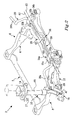
- FIG. 1 illustrates a suspension system 2 for a vehicle according to a first embodiment the invention.
- the vehicle has a frame 4, whereof only a portion is shown.
- the frame 4 has a front end 5, a right-hand side 6 and a left-hand side 8.
- the wheel suspension 10 comprises a lower link arm 12 and an upper link arm 14.
- the wheel (not illustrated) is connected by means of a knuckle (not illustrated) between the distal end 16 of the lower link arm 12 and the joint 17 of the upper link arm 14.
- the lower link arm 12 is pivotally connected to a damper 18 around axis A1.
- An anti-roll bar 20 connects the left-hand side wheel suspension 10 to the right-hand side wheel suspension.
- the anti-roll bar 20 is further connected to the frame 4 at a first connection 22a, 22b at each side of the frame 4 permitting rotational movement in relation to the frame around the longitudinal axis A2 of the anti-roll bar 20.
- the function of an anti-roll bar is to increase the stiffness of the suspension system in order to increase the resistance of the vehicle to roll in turns.
- the anti-roll bar 20 is U-shaped and comprises two lever portions 26a, 26b at each side with a central portion 28 along the longitudinal axis A2 in between.
- the lever portions 26a, 26b are located outside of the first connections 22a, 22b, while the central portion 28 is located in between the first connections 22a, 22b.
- a vertical motion of the wheel when e.g. driving over a hole in the road, is transferred via the lever portion 26a into a rotation and/or twist of the central portion 28 of the anti-roll bar 20.
- An outer link 29 is adapted to transfer the vertical movement of the wheel to the lever portion 26a, 26b of the anti-roll bar 20.
- the suspension system 2 further comprises a torsional spring bar 30, which is fixedly connected to the frame 4 at second connections 32a, 32b at each side of the frame 4.
- the torsional spring bar 30 extends parallel to the central portion 28 of the anti-roll bar 20.
- the first connection 22a, 22b at each side is combined with the second connection 32a, 32b at each side to form a common connection block 34a, 34b at each side, but the first and second connection may also be separate from each other.
- the anti-roll bar 20 is connected to the torsional spring bar 30 by means of a third connection 36.
- the third connection 36 is able to transfer a rotational and/or twisting movement of the anti-roll bar 20 into a torque of the torsional spring bar 30.
- the third connection 36 is located at essentially the mid-point of the anti-roll bar.
- the third connection 36 comprises a first bracket 38 fixed to the anti-roll bar 20, a second bracket 40 fixed to the torsional spring bar 30, and a link 42 connecting the first 38 and second 40 bracket.
- the link 42 is pivotally connected to the first bracket 38 around the axis A4, and to the second bracket 40 around the axis A5.
- the first 38 and second brackets 40 extend parallel to each other, in this case upwards when the wheels are in a neutral position.
- One or more extra connections (not illustrated) permitting rotational movement of the anti-roll bar 20 around the longitudinal axis A2 may be located in between the first connections 22a, 22b. There may also be located one or more extra connections (not illustrated) permitting rotational movement of the torsional spring bar 30 around the longitudinal axis A3 in between the second connections 32a, 32b. These extra connections may be helpful to prevent bending of the respective bars, since they connect the respective bar 20, 30 to the frame 4.
- the lower link arm 12 transfers the vertical movement via the outer link 29 to the lever arm 26a.
- the lever arm 26a transfers the movement into a rotational movement of the central portion 28 of the anti-roll bar 20 around the longitudinal axis A2. The same occurs at the other side of the vehicle.
- the rotational movement is further transferred via the third connection 36 to a torque of the torsional spring bar 30.
- the total resilient effect will be a function of the torsional resistance of the combination of the anti-roll bar 20, the third connection 36 and the torsional spring bar 30.
- the spring constant of the combined spring can be varied by varying lengths, cross-sections, geometries and material characteristics of the anti-roll bar 20, the third connection 36 and the torsional spring bar 30. Often the simplest way to select the spring constant is by adjustment of the lengths and geometry of the brackets 38, 40 and the link 42 of the third connection 36.
- the lever arms 26a and 26b will transfer two different amounts of vertical movement.
- the central portion 28 of the anti-roll bar 20 will thereby be subjected to a combination of rotation and twist around its longitudinal axis A2.
- these movements will be transferred as a torque to the torsional spring bar 30 via the third connection 36.
- the total resilient effect will be a function of the torsional resistance of the combination of the anti-roll bar 20, the third connection 36 and the torsional spring bar 30.
- the third connection 36 may be of any kind being able to transfer rotational and/or twisting movement of the central portion 28 of the anti-roll bar 20 into a torque of the torsional spring bar 30. Moreover, with an arrangement as in Figure 1 , it is possible to transfer the rotational and/or twisting movement of the anti-roll bar 20 into a torque of the torsional spring bar 30 without subjecting the torsional spring bar 30 to a bending force.
- a coil spring In a traditional suspension system, a coil spring would have been located on top of the damper 18, here indicated by dashed lines. However, according to the invention, that coil spring can be omitted and thus the height of the suspension is lowered.
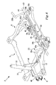
- FIG 2 illustrates a second embodiment of the invention. Since many parts are similar to in Figure 1 , the description will focus on the differences.
- the anti-roll bar 20 has a double U-shape.
- the outer U-shape is similar to in Figure 1 , permitting the lever arms 26a, 26b to transfer vertical motion into rotational motion.
- the central portion 28 is in itself U-shaped with the U essentially centred around the midpoint of the central portion 28.
- the torsional spring bar 30 has a similar U-shape as the central portion 28 of the anti-roll bar 20.
- the U of the anti-roll bar 20 and the U of the torsional spring bar 30 both extend downwards when the wheel suspension is in a neutral position. The U shapes are thus parallel.
- connection 36 in the form of the link 42 transfers movement between the anti-roll bar 20 and the torsional spring bar 30 at the bottom of the U. Due to the U-shape, no brackets as in Figure 1 are needed. As an alternative, it would also possible to have the U-shapes directed upwards.
- the central portion 28 of the anti-roll bar 20 and the torsional spring bar 30 may have different shapes, but in that case the shapes should be adapted to each other, so that one bar does not collide with the other during rotation and/or twist. The shapes should further be coordinated, so that the distance between the bars will be the same at the third connection 36.
- the second connection comprises an actuator 44a, 44b at each end of the torsional spring bar 30.
- the actuators 44a, 44b are able to twist the torsional spring bar 30 around its longitudinal axis A3.
- the actuators may be used for pre-tensioning of the torsional spring bar 30.
- the third connection 36 will transfer the movement into rotation of the central portion 28 of the anti-roll bar 20.
- the lever arms 26a, 26b Via the lever arms 26a, 26b, the movement is further transferred into a vertical movement of the wheel suspension 10.
- different load weights in the vehicle or different road conditions may make it desirable to be able to increase or decrease ground clearance of the vehicle. Increase and decrease, respectively, are chosen by the twisting direction of the pre-tensioning.
- the amount of pre-tensioning may be automatically set by the vehicle information system or may be set by the driver via a control unit.
- Figure 3 shows an embodiment with two actuators.
- a single actuator or two or more actuators may also be located anywhere along the torsional spring bar 30, and in that case the ends of the torsional spring bar 30 may be fixed by the second connection as described above.
- the actuator may be driven by an electrical motor.
- the length of the outer links 29 may also in that case be adjusted by the vehicle information system or may be adjusted by the driver via a control unit. It may also be possible to set the length of one or both of the outer links 29 at the production plant in order to compensate for a height difference between the left-hand side and right-hand side of the car, which may be a result of production tolerances.
- FIGs 1 to 3 illustrate the suspension system according to the invention for a double-wishbone suspension.
- the suspension system according to the invention is also applicable for other kinds of suspensions, such as for example a McPherson suspension, sometimes spelt MacPherson, as illustrated in Figure 4 .
- Figure 4 shows the wheel suspension 10 of the left-hand side 8 of the front end 5 of a vehicle.
- the wheel (not illustrated) is connected to the hub carrier 46, which in turn is pivotally connected to the lower link arm 12 and to the damper 18.
- the damper 18 is connected by a link 48 to the lever portion 26a of the anti-roll bar 20.
- the function of the suspension system is similar as explained above.
- the vertical movement of the wheel (not illustrated) is transferred by the link 48 to the lever portion 26a.
- the link 48 may have an adjustable length.
- Figures 1 - 4 disclose embodiments with a torsional spring bar 30 extending over the full width of the vehicle, parallel to the central portion of the anti-roll bar 20. It would be possible to instead use two or more torsional spring bars, for example one torsional spring bar for each wheel.
- the anti-roll bar 20 could in that case anyway typically extend over the full width of the vehicle.
- two or more torsional spring bars preferably extending essentially in parallel to each other, and which are coupled to each other and/ or to the anti-roll bar.
- two torsional spring bars having a small diameter may replace one torsional spring bar 30 with a large diameter.
- the coupling between the anti-roll bar 20 and the torsional spring bar 30 is by means of a link arrangement, but other arrangements are also possible, for example a gear wheel arrangement or a joint. If one of the bars 20, 30 is hollow, the other bar may be located inside the hollow bar. Such an arrangement would be space-efficient.
- the outer bar may be provided with slots, and the number and geometry of the slots may then be varied to select the desired spring characteristics.
Landscapes
- Engineering & Computer Science (AREA)
- Mechanical Engineering (AREA)
- Vehicle Body Suspensions (AREA)
Priority Applications (1)
| Application Number | Priority Date | Filing Date | Title |
|---|---|---|---|
| EP20090173137 EP2311670B1 (fr) | 2009-10-15 | 2009-10-15 | Système de suspension |
Applications Claiming Priority (1)
| Application Number | Priority Date | Filing Date | Title |
|---|---|---|---|
| EP20090173137 EP2311670B1 (fr) | 2009-10-15 | 2009-10-15 | Système de suspension |
Publications (2)
| Publication Number | Publication Date |
|---|---|
| EP2311670A1 true EP2311670A1 (fr) | 2011-04-20 |
| EP2311670B1 EP2311670B1 (fr) | 2012-08-15 |
Family
ID=41818331
Family Applications (1)
| Application Number | Title | Priority Date | Filing Date |
|---|---|---|---|
| EP20090173137 Active EP2311670B1 (fr) | 2009-10-15 | 2009-10-15 | Système de suspension |
Country Status (1)
| Country | Link |
|---|---|
| EP (1) | EP2311670B1 (fr) |
Cited By (2)
| Publication number | Priority date | Publication date | Assignee | Title |
|---|---|---|---|---|
| EP3354497A4 (fr) * | 2015-09-22 | 2019-06-19 | Beylin, Georgiy Volodimirovich | Suspension de véhicule « afw » (et variantes) |
| FR3096612A1 (fr) * | 2019-05-28 | 2020-12-04 | Renault S.A.S. | Train roulant de véhicule automobile comportant des moyens de réglage de la garde au sol |
Families Citing this family (1)
| Publication number | Priority date | Publication date | Assignee | Title |
|---|---|---|---|---|
| WO2022086502A1 (fr) * | 2020-10-20 | 2022-04-28 | Ford Global Technologies, Llc | Système de déconnexion arb à gradient de roulis amélioré et caractéristiques de sous-virage |
Citations (6)
| Publication number | Priority date | Publication date | Assignee | Title |
|---|---|---|---|---|
| US2688495A (en) * | 1951-04-05 | 1954-09-07 | Hubertus Josephus Van Doorne | Torsion rod suspension system for vehicles |
| EP0156705A1 (fr) * | 1984-03-08 | 1985-10-02 | AEROSPATIALE Société Nationale Industrielle | Suspension à bras oscillants pour un train de deux roues d'un véhicule et ensemble de tubes parallèles pour une telle suspension |
| EP0649764A1 (fr) * | 1993-10-22 | 1995-04-26 | Regie Nationale Des Usines Renault S.A. | Suspension de train arrière pour véhicule automobile |
| FR2794689A1 (fr) * | 1999-06-10 | 2000-12-15 | Peugeot Citroen Automobiles Sa | Suspension pour train de roues de vehicules |
| EP1679209A1 (fr) * | 2005-01-10 | 2006-07-12 | Renault S.A.S. | Dispositif de suspension pour barres de torsion |
| EP1837212A1 (fr) * | 2006-03-15 | 2007-09-26 | Bayerische Motoren Werke Aktiengesellschaft | Système de ressort pour une suspension de roue de véhicule |
-
2009
- 2009-10-15 EP EP20090173137 patent/EP2311670B1/fr active Active
Patent Citations (6)
| Publication number | Priority date | Publication date | Assignee | Title |
|---|---|---|---|---|
| US2688495A (en) * | 1951-04-05 | 1954-09-07 | Hubertus Josephus Van Doorne | Torsion rod suspension system for vehicles |
| EP0156705A1 (fr) * | 1984-03-08 | 1985-10-02 | AEROSPATIALE Société Nationale Industrielle | Suspension à bras oscillants pour un train de deux roues d'un véhicule et ensemble de tubes parallèles pour une telle suspension |
| EP0649764A1 (fr) * | 1993-10-22 | 1995-04-26 | Regie Nationale Des Usines Renault S.A. | Suspension de train arrière pour véhicule automobile |
| FR2794689A1 (fr) * | 1999-06-10 | 2000-12-15 | Peugeot Citroen Automobiles Sa | Suspension pour train de roues de vehicules |
| EP1679209A1 (fr) * | 2005-01-10 | 2006-07-12 | Renault S.A.S. | Dispositif de suspension pour barres de torsion |
| EP1837212A1 (fr) * | 2006-03-15 | 2007-09-26 | Bayerische Motoren Werke Aktiengesellschaft | Système de ressort pour une suspension de roue de véhicule |
Cited By (2)
| Publication number | Priority date | Publication date | Assignee | Title |
|---|---|---|---|---|
| EP3354497A4 (fr) * | 2015-09-22 | 2019-06-19 | Beylin, Georgiy Volodimirovich | Suspension de véhicule « afw » (et variantes) |
| FR3096612A1 (fr) * | 2019-05-28 | 2020-12-04 | Renault S.A.S. | Train roulant de véhicule automobile comportant des moyens de réglage de la garde au sol |
Also Published As
| Publication number | Publication date |
|---|---|
| EP2311670B1 (fr) | 2012-08-15 |
Similar Documents
| Publication | Publication Date | Title |
|---|---|---|
| EP0844935B1 (fr) | Amelioration des mecanismes de stabilisation en roulis pour systemes de suspension de vehicules | |
| US6793228B2 (en) | Anti-roll suspension for automobiles | |
| CA2913353C (fr) | Systeme de suspension semi-independante pour vehicule a plancher surbaisse | |
| US8746713B2 (en) | Wheel suspension for motor vehicles | |
| JP4592732B2 (ja) | 車両用サスペンション装置 | |
| US6672605B2 (en) | Vehicle suspension systems | |
| US8033556B2 (en) | Combined tramp rod and anti-roll bar | |
| US8573617B2 (en) | Wheel suspension for motor vehicles | |
| EP2255981A1 (fr) | Dispositif de suspension à barres de torsion pour véhicule | |
| US20090033142A1 (en) | Powered motor vehicle rear axle of a twist-beam axle type | |
| WO2003078185A1 (fr) | Suspension automobile anti-roulis a controle de direction | |
| WO2003074303A1 (fr) | Suspension anti-dévers pour véhicules | |
| US11186132B2 (en) | Suspension system for vehicle | |
| EP2311670B1 (fr) | Système de suspension | |
| EP1910108B1 (fr) | Suspension de roue individuelle | |
| EP1522433B1 (fr) | Anneau de serrage pour fixation axiale d'un stabilisateur | |
| EP0316285B1 (fr) | Suspensions du type McPherson pour des véhicules automobiles | |
| KR20160125410A (ko) | 개선된 결합구를 구비한 결합 가능한 차량 | |
| KR100527720B1 (ko) | 버스용 후륜 현가장치 | |
| US20220219503A1 (en) | Rear axle for a two-track vehicle and two-track vehicle with a rear axle | |
| CN115923427A (zh) | 主动稳定杆总成和具有其的车辆 | |
| KR19990059837A (ko) | 자동차의 토션빔 축형 리어 현가장치 | |
| CN109808439A (zh) | 机动车辆底盘的横向稳定装置 | |
| CN115610499A (zh) | 麦弗逊式独立悬架及车辆 | |
| Heißing et al. | Axles and Suspensions |
Legal Events
| Date | Code | Title | Description |
|---|---|---|---|
| PUAI | Public reference made under article 153(3) epc to a published international application that has entered the european phase |
Free format text: ORIGINAL CODE: 0009012 |
|
| AK | Designated contracting states |
Kind code of ref document: A1 Designated state(s): AT BE BG CH CY CZ DE DK EE ES FI FR GB GR HR HU IE IS IT LI LT LU LV MC MK MT NL NO PL PT RO SE SI SK SM TR |
|
| AX | Request for extension of the european patent |
Extension state: AL BA RS |
|
| RAP1 | Party data changed (applicant data changed or rights of an application transferred) |
Owner name: VOLVO CAR CORPORATION |
|
| 17P | Request for examination filed |
Effective date: 20111020 |
|
| 17Q | First examination report despatched |
Effective date: 20111109 |
|
| RIC1 | Information provided on ipc code assigned before grant |
Ipc: B60G 11/20 20060101ALI20120312BHEP Ipc: B60G 11/18 20060101AFI20120312BHEP Ipc: B60G 21/05 20060101ALI20120312BHEP Ipc: B60G 17/02 20060101ALI20120312BHEP |
|
| GRAP | Despatch of communication of intention to grant a patent |
Free format text: ORIGINAL CODE: EPIDOSNIGR1 |
|
| GRAS | Grant fee paid |
Free format text: ORIGINAL CODE: EPIDOSNIGR3 |
|
| GRAA | (expected) grant |
Free format text: ORIGINAL CODE: 0009210 |
|
| AK | Designated contracting states |
Kind code of ref document: B1 Designated state(s): AT BE BG CH CY CZ DE DK EE ES FI FR GB GR HR HU IE IS IT LI LT LU LV MC MK MT NL NO PL PT RO SE SI SK SM TR |
|
| REG | Reference to a national code |
Ref country code: GB Ref legal event code: FG4D Ref country code: CH Ref legal event code: EP Ref country code: AT Ref legal event code: REF Ref document number: 570621 Country of ref document: AT Kind code of ref document: T Effective date: 20120815 |
|
| REG | Reference to a national code |
Ref country code: IE Ref legal event code: FG4D |
|
| REG | Reference to a national code |
Ref country code: DE Ref legal event code: R096 Ref document number: 602009008946 Country of ref document: DE Effective date: 20121018 |
|
| REG | Reference to a national code |
Ref country code: SE Ref legal event code: TRGR |
|
| REG | Reference to a national code |
Ref country code: NL Ref legal event code: VDEP Effective date: 20120815 |
|
| REG | Reference to a national code |
Ref country code: AT Ref legal event code: MK05 Ref document number: 570621 Country of ref document: AT Kind code of ref document: T Effective date: 20120815 |
|
| PG25 | Lapsed in a contracting state [announced via postgrant information from national office to epo] |
Ref country code: NO Free format text: LAPSE BECAUSE OF FAILURE TO SUBMIT A TRANSLATION OF THE DESCRIPTION OR TO PAY THE FEE WITHIN THE PRESCRIBED TIME-LIMIT Effective date: 20121115 Ref country code: HR Free format text: LAPSE BECAUSE OF FAILURE TO SUBMIT A TRANSLATION OF THE DESCRIPTION OR TO PAY THE FEE WITHIN THE PRESCRIBED TIME-LIMIT Effective date: 20120815 Ref country code: IS Free format text: LAPSE BECAUSE OF FAILURE TO SUBMIT A TRANSLATION OF THE DESCRIPTION OR TO PAY THE FEE WITHIN THE PRESCRIBED TIME-LIMIT Effective date: 20121215 Ref country code: FI Free format text: LAPSE BECAUSE OF FAILURE TO SUBMIT A TRANSLATION OF THE DESCRIPTION OR TO PAY THE FEE WITHIN THE PRESCRIBED TIME-LIMIT Effective date: 20120815 Ref country code: AT Free format text: LAPSE BECAUSE OF FAILURE TO SUBMIT A TRANSLATION OF THE DESCRIPTION OR TO PAY THE FEE WITHIN THE PRESCRIBED TIME-LIMIT Effective date: 20120815 Ref country code: LT Free format text: LAPSE BECAUSE OF FAILURE TO SUBMIT A TRANSLATION OF THE DESCRIPTION OR TO PAY THE FEE WITHIN THE PRESCRIBED TIME-LIMIT Effective date: 20120815 |
|
| PG25 | Lapsed in a contracting state [announced via postgrant information from national office to epo] |
Ref country code: LV Free format text: LAPSE BECAUSE OF FAILURE TO SUBMIT A TRANSLATION OF THE DESCRIPTION OR TO PAY THE FEE WITHIN THE PRESCRIBED TIME-LIMIT Effective date: 20120815 Ref country code: BE Free format text: LAPSE BECAUSE OF FAILURE TO SUBMIT A TRANSLATION OF THE DESCRIPTION OR TO PAY THE FEE WITHIN THE PRESCRIBED TIME-LIMIT Effective date: 20120815 Ref country code: GR Free format text: LAPSE BECAUSE OF FAILURE TO SUBMIT A TRANSLATION OF THE DESCRIPTION OR TO PAY THE FEE WITHIN THE PRESCRIBED TIME-LIMIT Effective date: 20121116 Ref country code: PT Free format text: LAPSE BECAUSE OF FAILURE TO SUBMIT A TRANSLATION OF THE DESCRIPTION OR TO PAY THE FEE WITHIN THE PRESCRIBED TIME-LIMIT Effective date: 20121217 Ref country code: SI Free format text: LAPSE BECAUSE OF FAILURE TO SUBMIT A TRANSLATION OF THE DESCRIPTION OR TO PAY THE FEE WITHIN THE PRESCRIBED TIME-LIMIT Effective date: 20120815 Ref country code: PL Free format text: LAPSE BECAUSE OF FAILURE TO SUBMIT A TRANSLATION OF THE DESCRIPTION OR TO PAY THE FEE WITHIN THE PRESCRIBED TIME-LIMIT Effective date: 20120815 |
|
| PG25 | Lapsed in a contracting state [announced via postgrant information from national office to epo] |
Ref country code: NL Free format text: LAPSE BECAUSE OF FAILURE TO SUBMIT A TRANSLATION OF THE DESCRIPTION OR TO PAY THE FEE WITHIN THE PRESCRIBED TIME-LIMIT Effective date: 20120815 |
|
| PG25 | Lapsed in a contracting state [announced via postgrant information from national office to epo] |
Ref country code: RO Free format text: LAPSE BECAUSE OF FAILURE TO SUBMIT A TRANSLATION OF THE DESCRIPTION OR TO PAY THE FEE WITHIN THE PRESCRIBED TIME-LIMIT Effective date: 20120815 Ref country code: CZ Free format text: LAPSE BECAUSE OF FAILURE TO SUBMIT A TRANSLATION OF THE DESCRIPTION OR TO PAY THE FEE WITHIN THE PRESCRIBED TIME-LIMIT Effective date: 20120815 Ref country code: DK Free format text: LAPSE BECAUSE OF FAILURE TO SUBMIT A TRANSLATION OF THE DESCRIPTION OR TO PAY THE FEE WITHIN THE PRESCRIBED TIME-LIMIT Effective date: 20120815 Ref country code: ES Free format text: LAPSE BECAUSE OF FAILURE TO SUBMIT A TRANSLATION OF THE DESCRIPTION OR TO PAY THE FEE WITHIN THE PRESCRIBED TIME-LIMIT Effective date: 20121126 Ref country code: EE Free format text: LAPSE BECAUSE OF FAILURE TO SUBMIT A TRANSLATION OF THE DESCRIPTION OR TO PAY THE FEE WITHIN THE PRESCRIBED TIME-LIMIT Effective date: 20120815 |
|
| PG25 | Lapsed in a contracting state [announced via postgrant information from national office to epo] |
Ref country code: SK Free format text: LAPSE BECAUSE OF FAILURE TO SUBMIT A TRANSLATION OF THE DESCRIPTION OR TO PAY THE FEE WITHIN THE PRESCRIBED TIME-LIMIT Effective date: 20120815 Ref country code: IT Free format text: LAPSE BECAUSE OF FAILURE TO SUBMIT A TRANSLATION OF THE DESCRIPTION OR TO PAY THE FEE WITHIN THE PRESCRIBED TIME-LIMIT Effective date: 20120815 Ref country code: MC Free format text: LAPSE BECAUSE OF NON-PAYMENT OF DUE FEES Effective date: 20121031 |
|
| PLBE | No opposition filed within time limit |
Free format text: ORIGINAL CODE: 0009261 |
|
| STAA | Information on the status of an ep patent application or granted ep patent |
Free format text: STATUS: NO OPPOSITION FILED WITHIN TIME LIMIT |
|
| REG | Reference to a national code |
Ref country code: IE Ref legal event code: MM4A |
|
| 26N | No opposition filed |
Effective date: 20130516 |
|
| REG | Reference to a national code |
Ref country code: FR Ref legal event code: ST Effective date: 20130628 |
|
| PG25 | Lapsed in a contracting state [announced via postgrant information from national office to epo] |
Ref country code: BG Free format text: LAPSE BECAUSE OF FAILURE TO SUBMIT A TRANSLATION OF THE DESCRIPTION OR TO PAY THE FEE WITHIN THE PRESCRIBED TIME-LIMIT Effective date: 20121115 Ref country code: IE Free format text: LAPSE BECAUSE OF NON-PAYMENT OF DUE FEES Effective date: 20121015 |
|
| PG25 | Lapsed in a contracting state [announced via postgrant information from national office to epo] |
Ref country code: FR Free format text: LAPSE BECAUSE OF NON-PAYMENT OF DUE FEES Effective date: 20121031 |
|
| REG | Reference to a national code |
Ref country code: DE Ref legal event code: R097 Ref document number: 602009008946 Country of ref document: DE Effective date: 20130516 |
|
| PG25 | Lapsed in a contracting state [announced via postgrant information from national office to epo] |
Ref country code: MT Free format text: LAPSE BECAUSE OF FAILURE TO SUBMIT A TRANSLATION OF THE DESCRIPTION OR TO PAY THE FEE WITHIN THE PRESCRIBED TIME-LIMIT Effective date: 20120815 Ref country code: CY Free format text: LAPSE BECAUSE OF FAILURE TO SUBMIT A TRANSLATION OF THE DESCRIPTION OR TO PAY THE FEE WITHIN THE PRESCRIBED TIME-LIMIT Effective date: 20120815 |
|
| PG25 | Lapsed in a contracting state [announced via postgrant information from national office to epo] |
Ref country code: TR Free format text: LAPSE BECAUSE OF FAILURE TO SUBMIT A TRANSLATION OF THE DESCRIPTION OR TO PAY THE FEE WITHIN THE PRESCRIBED TIME-LIMIT Effective date: 20120815 |
|
| PG25 | Lapsed in a contracting state [announced via postgrant information from national office to epo] |
Ref country code: LU Free format text: LAPSE BECAUSE OF NON-PAYMENT OF DUE FEES Effective date: 20121015 Ref country code: SM Free format text: LAPSE BECAUSE OF FAILURE TO SUBMIT A TRANSLATION OF THE DESCRIPTION OR TO PAY THE FEE WITHIN THE PRESCRIBED TIME-LIMIT Effective date: 20120815 |
|
| REG | Reference to a national code |
Ref country code: CH Ref legal event code: PL |
|
| PG25 | Lapsed in a contracting state [announced via postgrant information from national office to epo] |
Ref country code: HU Free format text: LAPSE BECAUSE OF FAILURE TO SUBMIT A TRANSLATION OF THE DESCRIPTION OR TO PAY THE FEE WITHIN THE PRESCRIBED TIME-LIMIT Effective date: 20091015 Ref country code: CH Free format text: LAPSE BECAUSE OF NON-PAYMENT OF DUE FEES Effective date: 20131031 Ref country code: LI Free format text: LAPSE BECAUSE OF NON-PAYMENT OF DUE FEES Effective date: 20131031 |
|
| PG25 | Lapsed in a contracting state [announced via postgrant information from national office to epo] |
Ref country code: MK Free format text: LAPSE BECAUSE OF FAILURE TO SUBMIT A TRANSLATION OF THE DESCRIPTION OR TO PAY THE FEE WITHIN THE PRESCRIBED TIME-LIMIT Effective date: 20120815 |
|
| PGFP | Annual fee paid to national office [announced via postgrant information from national office to epo] |
Ref country code: SE Payment date: 20181211 Year of fee payment: 10 |
|
| PGFP | Annual fee paid to national office [announced via postgrant information from national office to epo] |
Ref country code: GB Payment date: 20181011 Year of fee payment: 10 |
|
| PG25 | Lapsed in a contracting state [announced via postgrant information from national office to epo] |
Ref country code: SE Free format text: LAPSE BECAUSE OF NON-PAYMENT OF DUE FEES Effective date: 20191016 |
|
| GBPC | Gb: european patent ceased through non-payment of renewal fee |
Effective date: 20191015 |
|
| PG25 | Lapsed in a contracting state [announced via postgrant information from national office to epo] |
Ref country code: GB Free format text: LAPSE BECAUSE OF NON-PAYMENT OF DUE FEES Effective date: 20191015 |
|
| P01 | Opt-out of the competence of the unified patent court (upc) registered |
Effective date: 20231212 |
|
| PGFP | Annual fee paid to national office [announced via postgrant information from national office to epo] |
Ref country code: DE Payment date: 20230920 Year of fee payment: 15 |