EP2311657A2 - Profil de bande de roulement d'un pneu de véhicule - Google Patents
Profil de bande de roulement d'un pneu de véhicule Download PDFInfo
- Publication number
- EP2311657A2 EP2311657A2 EP10178576A EP10178576A EP2311657A2 EP 2311657 A2 EP2311657 A2 EP 2311657A2 EP 10178576 A EP10178576 A EP 10178576A EP 10178576 A EP10178576 A EP 10178576A EP 2311657 A2 EP2311657 A2 EP 2311657A2
- Authority
- EP
- European Patent Office
- Prior art keywords
- groove
- rib
- radial
- radially
- tire
- Prior art date
- Legal status (The legal status is an assumption and is not a legal conclusion. Google has not performed a legal analysis and makes no representation as to the accuracy of the status listed.)
- Granted
Links
Images


Classifications
-
- B—PERFORMING OPERATIONS; TRANSPORTING
- B60—VEHICLES IN GENERAL
- B60C—VEHICLE TYRES; TYRE INFLATION; TYRE CHANGING; CONNECTING VALVES TO INFLATABLE ELASTIC BODIES IN GENERAL; DEVICES OR ARRANGEMENTS RELATED TO TYRES
- B60C11/00—Tyre tread bands; Tread patterns; Anti-skid inserts
- B60C11/03—Tread patterns
- B60C11/0306—Patterns comprising block rows or discontinuous ribs
- B60C11/0309—Patterns comprising block rows or discontinuous ribs further characterised by the groove cross-section
-
- B—PERFORMING OPERATIONS; TRANSPORTING
- B60—VEHICLES IN GENERAL
- B60C—VEHICLE TYRES; TYRE INFLATION; TYRE CHANGING; CONNECTING VALVES TO INFLATABLE ELASTIC BODIES IN GENERAL; DEVICES OR ARRANGEMENTS RELATED TO TYRES
- B60C11/00—Tyre tread bands; Tread patterns; Anti-skid inserts
- B60C11/03—Tread patterns
- B60C11/04—Tread patterns in which the raised area of the pattern consists only of continuous circumferential ribs, e.g. zig-zag
- B60C11/042—Tread patterns in which the raised area of the pattern consists only of continuous circumferential ribs, e.g. zig-zag further characterised by the groove cross-section
- B60C11/045—Tread patterns in which the raised area of the pattern consists only of continuous circumferential ribs, e.g. zig-zag further characterised by the groove cross-section the groove walls having a three-dimensional shape
-
- B—PERFORMING OPERATIONS; TRANSPORTING
- B60—VEHICLES IN GENERAL
- B60C—VEHICLE TYRES; TYRE INFLATION; TYRE CHANGING; CONNECTING VALVES TO INFLATABLE ELASTIC BODIES IN GENERAL; DEVICES OR ARRANGEMENTS RELATED TO TYRES
- B60C11/00—Tyre tread bands; Tread patterns; Anti-skid inserts
- B60C11/03—Tread patterns
- B60C11/13—Tread patterns characterised by the groove cross-section, e.g. for buttressing or preventing stone-trapping
- B60C11/1307—Tread patterns characterised by the groove cross-section, e.g. for buttressing or preventing stone-trapping with special features of the groove walls
- B60C11/1315—Tread patterns characterised by the groove cross-section, e.g. for buttressing or preventing stone-trapping with special features of the groove walls having variable inclination angles, e.g. warped groove walls
-
- B—PERFORMING OPERATIONS; TRANSPORTING
- B60—VEHICLES IN GENERAL
- B60C—VEHICLE TYRES; TYRE INFLATION; TYRE CHANGING; CONNECTING VALVES TO INFLATABLE ELASTIC BODIES IN GENERAL; DEVICES OR ARRANGEMENTS RELATED TO TYRES
- B60C11/00—Tyre tread bands; Tread patterns; Anti-skid inserts
- B60C11/03—Tread patterns
- B60C11/13—Tread patterns characterised by the groove cross-section, e.g. for buttressing or preventing stone-trapping
- B60C11/1307—Tread patterns characterised by the groove cross-section, e.g. for buttressing or preventing stone-trapping with special features of the groove walls
- B60C11/1323—Tread patterns characterised by the groove cross-section, e.g. for buttressing or preventing stone-trapping with special features of the groove walls asymmetric
Definitions
- the invention relates to a tread pattern of a pneumatic vehicle tire with at least one radially extending ribs axially delimited over the circumference of the tire and extending over the circumference of the tire, oriented in the circumferential direction U, which are formed with a maximum groove depth T and in the radial direction R is bounded in each case by a groove bottom and in both axial directions of extension in each case by a groove wall, each of which forms a groove edge facing rib of one of the two ribs, wherein the two groove walls respectively from the groove bottom radially outward to the respective rib edge radially outward extending boundary surface and each having a radially inner and a radially outer extension region, of which the radially inner extension region is formed starting from the groove bottom in the radial direction with an extension height h (0.07T) ⁇ h ⁇ (0.45T), where at the rib flanks in the radially inner extension region in all sectional planes that include the tire axis, either each form
- Such tread profiles are known. For good aquaplaning properties, it is desirable to form such rectilinear circumferential grooves without interference. Especially in the case of profiles with circumferential ribs, in which the ribs prevent a lateral outflow, the trouble-free flow through the circumferential groove to achieve good aquaplaning properties is particularly important. However, such straightforward exists Circumferential grooves the risk of the formation of standing waves in the air flow, which may cause unpleasant whistling or hissing noise to human hearing.
- stiffening short extension portions in which from the groove wall by means of suitable surfaces stiffening areas are formed, which extend into the groove.
- stiffening elements can also hinder the flow of water as disruptive elements, whereby the aquaplaning properties can be adversely affected.
- large, completely rectilinear sections are formed between the stiffening sections, which are distributed in isolated fashion over the circumference, which furthermore allow the formation of standing waves in the case of air flow.
- the invention has for its object to provide a tread pattern of a pneumatic vehicle tire according to the features of the preamble, are made possible with simple means despite circumferential ribs and circumferential groove good aquaplaning properties while avoiding disturbing noise.
- the object is achieved by forming a tread pattern of a pneumatic vehicle tire with at least one axially extending over the circumference of the tire radially raised ribs and extending over the circumference of the tire, aligned in the circumferential direction U groove formed with a maximum groove depth T and in the radial Direction R is limited inwardly by a groove bottom and in both axial directions of extension in each case by a groove wall, the in each case a rib flank facing the groove forms one of the two ribs, wherein the two groove walls each extend radially outward from the groove bottom up to the lateral surface delimiting the respective rib flank and each have a radially inner and a radially outer extent region, of which the radially inner extension region is formed starting from the groove bottom in the radial direction with an extension height h of (0.07T) ⁇ h ⁇ (0.45T), wherein the rib flanks in the radially inner extension region either in each of the cutting planes which include the tire axi
- the training allows despite circumferential ribs formed between them circumferential groove trouble-free with uniform large, open flow cross-section over the entire circumference, whereby water over the entire life cycle can be smoothly derived from the profile and the risk of aquaplaning is reduced.
- the alternately changing over the entire circumference inclined surfaces of the radially inner extension region hinder the formation of a uniform air flow and the emergence of standing waves, whereby the risk of noise is reduced.
- each one opposite the first and second peripheral portion shorter transition portion is formed in which at both rib edges in each case in the radially inner extension region of the inclination angle or the radius of curvature along the extent of the groove steadily - especially continuously - changes.
- the smooth transitions lead to further reduction of turbulence, which further promotes positive aquaplaning properties.
- the one rib edge in its radially inner extension region respectively in the first peripheral portions with inclination angles ⁇ 1 and in the second peripheral portions with inclination angles ⁇ 2 relative to the radial R and the other rib edge in its radial inner extension region is respectively formed in the first peripheral sections with inclination angles ⁇ 1 and in the second peripheral sections with inclination angles ⁇ 2 with respect to the radial R with ⁇ 1 > ⁇ 2 and with ⁇ 1 ⁇ 2 , with 35 ° ⁇ 1 ⁇ 45 °, 35 ° ⁇ ⁇ 2 ⁇ 45 °, 35 ° ⁇ ⁇ 1 ⁇ 45 ° and 35 ° ⁇ 2 ⁇ 45 °.
- the radially outer extension region of the first rib edge in all the tire axis having cutting planes has a substantially rectilinear sectional contour with inclination angles ⁇ to the radial R and the radially outer extent of the second rib edge in all the tire axis Sectional planes has a substantially straight-line sectional contour with inclination angles ⁇ to the radial R, wherein in particular 0 ° ⁇ ⁇ ⁇ 15 ° and 0 ° ⁇ ⁇ ⁇ 15 °.
- the radially outer extension portion of the first rib edge is formed in the first peripheral portions of the groove with inclination angles ⁇ 1 to the radial R and in the second peripheral portions of the groove with inclination angles ⁇ 2 to the radial R
- the radially outer extension portion of the second rib edge is formed in the first peripheral portions of the groove with inclination angles ⁇ 1 to the radial R and in the second circumferential portions of the groove with inclination angles ⁇ 2 to the radial R, ⁇ 1 ⁇ 2 and ⁇ 1 > ⁇ 2 .
- the advantages of the alternately formed peripheral sections can be implemented in a simple manner with a uniform course of the circumferential outer surface and groove flank forming the bottom contact surface and edge edge profiles formed from the groove flank and groove bottom. For new tires this allows a further improved noise reduction with improved aquaplaning properties.
- the noise is further minimized by the minimized risk of vibration excitation on the lateral surface.
- the Figure 1 to 5 show a section of a tread pattern of a pneumatic vehicle tire for passenger car tires of radial design with two in the axial direction A of the pneumatic vehicle tire within the ground contact surface side by side, over the entire circumference of the vehicle pneumatic tire extending and aligned in the circumferential direction U circumferential ribs 2 and 3, in the axial direction A through a circumferentially extending over the entire circumference of the pneumatic vehicle tire and aligned in the circumferential direction U circumferential groove 1 are spaced from each other.
- the circumferential groove 1 is in a known manner from a over the entire circumference of the pneumatic vehicle tire, aligned in the circumferential direction U and the circumferential groove 1 radially inward toward the tire limiting groove bottom 4, from a in the axial direction A, the circumferential groove 1 to the circumferential rib 2 towards limiting the rib flank 5 of the circumferential rib 2 forming groove wall and formed from a in the axial direction A, the circumferential groove 1 to the circumferential rib 3 towards limiting the rib edge 6 of the circumferential rib 3 forming groove wall.
- the rib flank 5 is formed from a radially inner extension region 8 and from a radially outer extension region 7.
- the groove flank 6 is formed from a radially inner extension region 10 and a radially outer extension region 9.
- the two radial inner extension regions 8 and 10 extend starting from the groove bottom 4 of the circumferential groove 1 in the radial direction R of the pneumatic vehicle tire to the outside over an extension height h.
- the radially outer extension region 7 of the rib flank 5 extends in the radial direction R, starting from the radially inner extension region 8 to the circumferential rib 2 radially outwardly delimiting, the road contact surface forming lateral surface and intersects this in a sectional contour line 14.
- the radially outer extension region 9 of Rib edge 6 extends in the radial direction R outward from the radially inner extension region 10 to the peripheral rib 3 radially outwardly bounding, the road contact surface forming lateral surface and intersects them in a sectional contour line 15.
- the sectional contour lines 14 and 15 are respectively rectilinear over the Entire circumference of the pneumatic vehicle tire extends aligned in the circumferential direction U.
- the radially inner extension region 8 of the rib flank 5 intersects the groove bottom 4 in a sectional contour line 16.
- the radially inner extension region 10 of the rib flank 6 intersects the groove bottom 4 in a sectional contour line 17.
- the cut contour lines 16 and 17 are each aligned rectilinearly parallel to one another in the circumferential direction U and extend over the entire circumference of the pneumatic vehicle tire.
- the radial extension height h of the radially inner extension regions 8 and 9 is formed with (0.07 T) ⁇ h ⁇ (0.45 T), where T is the groove depth of the circumferential groove 1, which is the maximum distance between the radial direction R measured
- T is the groove depth of the circumferential groove 1, which is the maximum distance between the radial direction R measured
- the lateral surface of the profile in the region of the circumferential groove 1 and the groove bottom 4 indicates the new tire.
- the groove depth T is chosen so that 6.5 mm T ⁇ 9 mm.
- the extension height h is selected so that 0.5 mm ⁇ h ⁇ 4 mm.
- the circumferential groove 1 is formed in the circumferential direction U over the entire circumference of the vehicle pneumatic tire in an alternating order formed first peripheral portions 11 of the circumferential length L 1 and second peripheral portions 12 of the circumferential length L 2 and short with respect to the circumferential lengths L 1 and L 2 between the alternating circumferential sections 11 and 12 formed transition sections 13 of length L 3rd
- the circumferential lengths L 1 and L 2 are selected with a length from a range between 20 and 100 mm inclusive.
- the circumferential length L 3 is L 3 > 1 mm, but significantly smaller than L 1 and L 2 and extends more than 1/5 of the shorter of the two extension lengths L 1 and L 2 , the first and second peripheral portions 11 separated from the respective transition section 13 and 12.
- a first circumferential section 11 with a length L 1 50 mm
- the transition section 13 with a length L 3 separating the two peripheral sections 11 and 12 in the circumferential direction U 5 mm formed.
- peripheral portions 11 and 12 are formed in accordance with a suitable Pitch réellever whatsoever the tire tread with over the circumference of the tire of different lengths.
- the radially outer extension regions 7 and the radially inner extension region 8 of the rib flank 5 and the radially outer extension region 9 and the radially inner extension region 10 of the rib flank 6 are in this case in the radial direction R outwardly inclined in each case from the axial position of the groove center.
- ⁇ 1 > ⁇ 2 , ⁇ 1 ⁇ 2 , ⁇ 1 ⁇ 2 and ⁇ 1 > ⁇ 2 are in this case in the radial direction R outwardly inclined in each case from the axial position of the groove center.
- ⁇ 1 (1/2) (90 ° - ⁇ 1 )
- ⁇ 2 (1/2) (90 ° - ⁇ 2 )
- ⁇ 1 (1/2) (90 ° - ⁇ 1 )
- ⁇ 2 (1/2) (90 ° - ⁇ 2 ).
- angles ⁇ 1 , ⁇ 2 , ⁇ 1 and ⁇ 2 are each selected from an angle range between 0 ° and 15 ° inclusive.
- angles ⁇ 1 , ⁇ 2 , ⁇ 1 and ⁇ 2 are chosen so that 35 ° ⁇ 1 ⁇ 45 °, 35 ° ⁇ ⁇ 2 ⁇ 45 °, 35 ° ⁇ 1 ⁇ 45 ° and 35 ° ⁇ 2 ⁇ 45 °.
- ⁇ 1 40 °
- ⁇ 2 37 °
- ⁇ 1 37 ° and ⁇ 2 40 °.
- the radially inner extension portions 8 and 10 are respectively formed over the entire circumference of the tire in all the tire axis having cut planes with a measured in the axial direction A extension width b, wherein b in both the first peripheral portions 11 and in the second peripheral portions 12 and in the Transition portions 13 each have at least 2mm and at most the value of (B / 2), wherein B is the respective measure of the axial extent of the groove on the radially outer surface of the tire, with 4 mm ⁇ B ⁇ 25 mm.
- the radially outer extension region 7 is formed with a continuously changing angle of inclination ⁇ flowing in this transition section 13, starting from the inclination angle ⁇ 1 of the adjacent first peripheral section 11 up to the inclination angle ⁇ 2 of the adjacent second peripheral section 12, a smooth transition of the inclination angle ⁇ he follows.
- the radially inner extension region 10 is formed with a continuously changed inclination angle ⁇ starting from the inclination angle ⁇ 1 of the adjacent first peripheral section 11 up to the inclination angle ⁇ 2 of the adjacent second peripheral section 12.
- the radially outer extension section 9 in the transition section 13, starting from the inclination angle ⁇ 1 of the adjacent first peripheral section 11 to the inclination angle ⁇ 2 of the adjacent second peripheral portion 12 formed with a continuously changing inclination angle ⁇ .
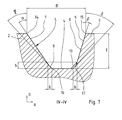
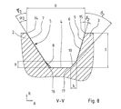
- FIGS. 6 to 8 show an embodiment in which ⁇ 1 > ⁇ 2 , ⁇ 1 ⁇ 2 , ⁇ 1 ⁇ 2 and ⁇ 1 > ⁇ 2 and ⁇ 1 > ⁇ 2 , ⁇ 2 > ⁇ 1 , ⁇ 1 ⁇ 2 and ⁇ 2 ⁇ 1 is selected.
- This embodiment causes an asymmetrical cross section of the circumferential groove over the entire circumference of the pneumatic vehicle tire.
- the in the FIGS. 3 to 5 shown embodiment show a contrast symmetrical structure of the circumferential groove.
- angles ⁇ 1 , ⁇ 2 , ⁇ 1 and ⁇ 2 are chosen so that 35 ° ⁇ 2 ⁇ 45 ° and 35 ° ⁇ 2 ⁇ 45 °.
- ⁇ 1 40 °
- ⁇ 2 35 °
- ⁇ 1 37 °
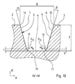
- FIGS. 9 to 12 show a different embodiment of the circumferential groove 1 as shown in the FIGS. 3 to 5 .
- the radially inner extending portion 8 of the rib flank 5 in the first peripheral portion 11 has a curved contour with radius of curvature R1 to a center of curvature M 1 on the side facing away from the rib flank 5 side of the tread and in the second circumferential extension portion 12 has a curved contour with a radius R 3 around a center of curvature M 3 with R 1 > R 3 .
- the radial inner extension region 10 of the rib flank 6 has in the first peripheral portion 11 a curved contour with a radius of curvature R 2 around a center of curvature M 2 and in the second circumferential portion 12 a curved contour with a radius of curvature R 4 around a center of curvature M 4 on with R 4 > R 2 ,
- the radially inner extension portion 8 of the rib flank 5 extends in the first peripheral portion 11 - as in FIG. 9 is shown on a basis of the groove bottom 4 measured radial extension height h 1 and in the second peripheral portion 12 - as in FIG. 11 is shown over a radial extent h 3 from the groove bottom 14 with h 1 > h 3 .
- the radially inner extension portion 10 of the rib flank 6 extends in the first peripheral portion 11 - as in FIG. 9 is shown in each case via a measured from the bottom of the groove 4 radial extension height h 2 and in the second peripheral portion 12 - as in FIG. 11 is shown - over a height h 4 with h 4 > h 2 .
- transition portion 13 proceeds from the adjacent first peripheral portion 11 to the adjacent second peripheral portion 12 with continuous decrease in the radial extension height h of the radially inner extension region 8, starting from the height h 1 in the first peripheral portion 11 to the height h 3 in the second peripheral portion 12 of the radius of curvature R. K continuously from the radius of curvature R 1 in the first peripheral portion 11 to the radius of curvature R 3 in the second peripheral portion 12 via.
- the radius of curvature R K continuously from the radius of curvature R 2 in the first peripheral portion 11 to the radius of curvature R 4 in the second peripheral portion 12 via.
- the radii of curvature R 1 , R 2 , R 3 and R 4 are formed from a value range between 0.5mm and 4mm.
Landscapes
- Engineering & Computer Science (AREA)
- Mechanical Engineering (AREA)
- Tires In General (AREA)
Applications Claiming Priority (1)
| Application Number | Priority Date | Filing Date | Title |
|---|---|---|---|
| DE200910044244 DE102009044244A1 (de) | 2009-10-14 | 2009-10-14 | Laufstreifenprofil eines Fahrzeugluftreifens |
Publications (3)
| Publication Number | Publication Date |
|---|---|
| EP2311657A2 true EP2311657A2 (fr) | 2011-04-20 |
| EP2311657A3 EP2311657A3 (fr) | 2013-02-27 |
| EP2311657B1 EP2311657B1 (fr) | 2016-08-31 |
Family
ID=43466388
Family Applications (1)
| Application Number | Title | Priority Date | Filing Date |
|---|---|---|---|
| EP10178576.4A Not-in-force EP2311657B1 (fr) | 2009-10-14 | 2010-09-23 | Profil de bande de roulement d'un pneu de véhicule |
Country Status (2)
| Country | Link |
|---|---|
| EP (1) | EP2311657B1 (fr) |
| DE (1) | DE102009044244A1 (fr) |
Citations (1)
| Publication number | Priority date | Publication date | Assignee | Title |
|---|---|---|---|---|
| US20050076986A1 (en) | 2002-01-18 | 2005-04-14 | Bridgestone Corporation | Pneumatic tire |
Family Cites Families (3)
| Publication number | Priority date | Publication date | Assignee | Title |
|---|---|---|---|---|
| US4550756A (en) * | 1984-01-16 | 1985-11-05 | The Goodyear Tire & Rubber Company | Pneumatic tire tread |
| DE4416435A1 (de) * | 1994-05-10 | 1996-02-01 | Uniroyal Englebert Gmbh | Laufflächenprofil |
| JP4562137B2 (ja) * | 2003-12-16 | 2010-10-13 | 株式会社ブリヂストン | 重荷重用空気入りタイヤ |
-
2009
- 2009-10-14 DE DE200910044244 patent/DE102009044244A1/de not_active Withdrawn
-
2010
- 2010-09-23 EP EP10178576.4A patent/EP2311657B1/fr not_active Not-in-force
Patent Citations (1)
| Publication number | Priority date | Publication date | Assignee | Title |
|---|---|---|---|---|
| US20050076986A1 (en) | 2002-01-18 | 2005-04-14 | Bridgestone Corporation | Pneumatic tire |
Also Published As
| Publication number | Publication date |
|---|---|
| EP2311657B1 (fr) | 2016-08-31 |
| DE102009044244A1 (de) | 2011-05-12 |
| EP2311657A3 (fr) | 2013-02-27 |
Similar Documents
| Publication | Publication Date | Title |
|---|---|---|
| EP1926610B1 (fr) | Profil de surface de roulement presentant des rainures circonferentielles asymetriques | |
| DE102015202613A1 (de) | Fahrzeugluftreifen | |
| EP3388256A1 (fr) | Pneumatique de véhicule | |
| EP2636544A1 (fr) | Pneus de véhicule | |
| EP2864137B1 (fr) | Bande de roulement de pneumatique | |
| EP2560830A1 (fr) | Pneu de véhicule | |
| EP3194183B1 (fr) | Pneumatique de véhicule | |
| EP2455235B1 (fr) | Profil de bande de roulement d'un bandage pneumatique de véhicule | |
| EP2377696B1 (fr) | Profil de bande de roulement d'un bandage pneumatique de véhicule | |
| EP2457745B1 (fr) | Pneus de véhicule | |
| DE102019206654A1 (de) | Fahrzeugluftreifen | |
| EP3100872B1 (fr) | Pneumatiques de véhicule | |
| EP3628511B1 (fr) | Pneumatiques de véhicule | |
| EP3560735B1 (fr) | Pneu de véhicule utilitaire | |
| EP2119574A1 (fr) | Profil de surface de roulement d'un pneu de véhicule | |
| DE102012105120A1 (de) | Fahrzeugluftreifen | |
| EP2390116B1 (fr) | Profil de bande de roulement d'un bandage pneumatique de véhicule | |
| EP2311657B1 (fr) | Profil de bande de roulement d'un pneu de véhicule | |
| DE102012101760A1 (de) | Fahrzeugluftreifen | |
| EP2914448B1 (fr) | Pneumatiques de véhicule | |
| DE102020205836A1 (de) | Fahrzeugluftreifen | |
| EP2253485B1 (fr) | Profil de bande de roulement d'une bande pneumatique de véhicule | |
| EP3890994B1 (fr) | Profil de bande de roulement d'un pneu de véhicule | |
| EP2500186B1 (fr) | Pneus de véhicule avec base de rainure partiellement élévée | |
| EP2676813B1 (fr) | Bande de roulement pour pneu de véhicule |
Legal Events
| Date | Code | Title | Description |
|---|---|---|---|
| PUAI | Public reference made under article 153(3) epc to a published international application that has entered the european phase |
Free format text: ORIGINAL CODE: 0009012 |
|
| AK | Designated contracting states |
Kind code of ref document: A2 Designated state(s): AL AT BE BG CH CY CZ DE DK EE ES FI FR GB GR HR HU IE IS IT LI LT LU LV MC MK MT NL NO PL PT RO SE SI SK SM TR |
|
| AX | Request for extension of the european patent |
Extension state: BA ME RS |
|
| PUAL | Search report despatched |
Free format text: ORIGINAL CODE: 0009013 |
|
| AK | Designated contracting states |
Kind code of ref document: A3 Designated state(s): AL AT BE BG CH CY CZ DE DK EE ES FI FR GB GR HR HU IE IS IT LI LT LU LV MC MK MT NL NO PL PT RO SE SI SK SM TR |
|
| AX | Request for extension of the european patent |
Extension state: BA ME RS |
|
| RIC1 | Information provided on ipc code assigned before grant |
Ipc: B60C 11/04 20060101AFI20130124BHEP Ipc: B60C 11/13 20060101ALI20130124BHEP Ipc: B60C 11/03 20060101ALI20130124BHEP |
|
| 17P | Request for examination filed |
Effective date: 20130827 |
|
| RBV | Designated contracting states (corrected) |
Designated state(s): AL AT BE BG CH CY CZ DE DK EE ES FI FR GB GR HR HU IE IS IT LI LT LU LV MC MK MT NL NO PL PT RO SE SI SK SM TR |
|
| GRAP | Despatch of communication of intention to grant a patent |
Free format text: ORIGINAL CODE: EPIDOSNIGR1 |
|
| INTG | Intention to grant announced |
Effective date: 20160510 |
|
| INTG | Intention to grant announced |
Effective date: 20160517 |
|
| GRAS | Grant fee paid |
Free format text: ORIGINAL CODE: EPIDOSNIGR3 |
|
| GRAA | (expected) grant |
Free format text: ORIGINAL CODE: 0009210 |
|
| AK | Designated contracting states |
Kind code of ref document: B1 Designated state(s): AL AT BE BG CH CY CZ DE DK EE ES FI FR GB GR HR HU IE IS IT LI LT LU LV MC MK MT NL NO PL PT RO SE SI SK SM TR |
|
| REG | Reference to a national code |
Ref country code: CH Ref legal event code: EP Ref country code: GB Ref legal event code: FG4D Free format text: NOT ENGLISH |
|
| REG | Reference to a national code |
Ref country code: IE Ref legal event code: FG4D Free format text: LANGUAGE OF EP DOCUMENT: GERMAN Ref country code: FR Ref legal event code: PLFP Year of fee payment: 7 |
|
| REG | Reference to a national code |
Ref country code: DE Ref legal event code: R096 Ref document number: 502010012288 Country of ref document: DE |
|
| REG | Reference to a national code |
Ref country code: AT Ref legal event code: REF Ref document number: 824653 Country of ref document: AT Kind code of ref document: T Effective date: 20161015 |
|
| REG | Reference to a national code |
Ref country code: LT Ref legal event code: MG4D |
|
| REG | Reference to a national code |
Ref country code: NL Ref legal event code: MP Effective date: 20160831 |
|
| PG25 | Lapsed in a contracting state [announced via postgrant information from national office to epo] |
Ref country code: LT Free format text: LAPSE BECAUSE OF FAILURE TO SUBMIT A TRANSLATION OF THE DESCRIPTION OR TO PAY THE FEE WITHIN THE PRESCRIBED TIME-LIMIT Effective date: 20160831 Ref country code: FI Free format text: LAPSE BECAUSE OF FAILURE TO SUBMIT A TRANSLATION OF THE DESCRIPTION OR TO PAY THE FEE WITHIN THE PRESCRIBED TIME-LIMIT Effective date: 20160831 Ref country code: NO Free format text: LAPSE BECAUSE OF FAILURE TO SUBMIT A TRANSLATION OF THE DESCRIPTION OR TO PAY THE FEE WITHIN THE PRESCRIBED TIME-LIMIT Effective date: 20161130 Ref country code: HR Free format text: LAPSE BECAUSE OF FAILURE TO SUBMIT A TRANSLATION OF THE DESCRIPTION OR TO PAY THE FEE WITHIN THE PRESCRIBED TIME-LIMIT Effective date: 20160831 |
|
| PG25 | Lapsed in a contracting state [announced via postgrant information from national office to epo] |
Ref country code: ES Free format text: LAPSE BECAUSE OF FAILURE TO SUBMIT A TRANSLATION OF THE DESCRIPTION OR TO PAY THE FEE WITHIN THE PRESCRIBED TIME-LIMIT Effective date: 20160831 Ref country code: NL Free format text: LAPSE BECAUSE OF FAILURE TO SUBMIT A TRANSLATION OF THE DESCRIPTION OR TO PAY THE FEE WITHIN THE PRESCRIBED TIME-LIMIT Effective date: 20160831 Ref country code: BE Free format text: LAPSE BECAUSE OF NON-PAYMENT OF DUE FEES Effective date: 20160930 Ref country code: LV Free format text: LAPSE BECAUSE OF FAILURE TO SUBMIT A TRANSLATION OF THE DESCRIPTION OR TO PAY THE FEE WITHIN THE PRESCRIBED TIME-LIMIT Effective date: 20160831 Ref country code: GR Free format text: LAPSE BECAUSE OF FAILURE TO SUBMIT A TRANSLATION OF THE DESCRIPTION OR TO PAY THE FEE WITHIN THE PRESCRIBED TIME-LIMIT Effective date: 20161201 Ref country code: SE Free format text: LAPSE BECAUSE OF FAILURE TO SUBMIT A TRANSLATION OF THE DESCRIPTION OR TO PAY THE FEE WITHIN THE PRESCRIBED TIME-LIMIT Effective date: 20160831 |
|
| PG25 | Lapsed in a contracting state [announced via postgrant information from national office to epo] |
Ref country code: EE Free format text: LAPSE BECAUSE OF FAILURE TO SUBMIT A TRANSLATION OF THE DESCRIPTION OR TO PAY THE FEE WITHIN THE PRESCRIBED TIME-LIMIT Effective date: 20160831 Ref country code: RO Free format text: LAPSE BECAUSE OF FAILURE TO SUBMIT A TRANSLATION OF THE DESCRIPTION OR TO PAY THE FEE WITHIN THE PRESCRIBED TIME-LIMIT Effective date: 20160831 |
|
| REG | Reference to a national code |
Ref country code: CH Ref legal event code: PL |
|
| PG25 | Lapsed in a contracting state [announced via postgrant information from national office to epo] |
Ref country code: PL Free format text: LAPSE BECAUSE OF FAILURE TO SUBMIT A TRANSLATION OF THE DESCRIPTION OR TO PAY THE FEE WITHIN THE PRESCRIBED TIME-LIMIT Effective date: 20160831 Ref country code: PT Free format text: LAPSE BECAUSE OF FAILURE TO SUBMIT A TRANSLATION OF THE DESCRIPTION OR TO PAY THE FEE WITHIN THE PRESCRIBED TIME-LIMIT Effective date: 20170102 Ref country code: SK Free format text: LAPSE BECAUSE OF FAILURE TO SUBMIT A TRANSLATION OF THE DESCRIPTION OR TO PAY THE FEE WITHIN THE PRESCRIBED TIME-LIMIT Effective date: 20160831 Ref country code: SM Free format text: LAPSE BECAUSE OF FAILURE TO SUBMIT A TRANSLATION OF THE DESCRIPTION OR TO PAY THE FEE WITHIN THE PRESCRIBED TIME-LIMIT Effective date: 20160831 Ref country code: BG Free format text: LAPSE BECAUSE OF FAILURE TO SUBMIT A TRANSLATION OF THE DESCRIPTION OR TO PAY THE FEE WITHIN THE PRESCRIBED TIME-LIMIT Effective date: 20161130 Ref country code: DK Free format text: LAPSE BECAUSE OF FAILURE TO SUBMIT A TRANSLATION OF THE DESCRIPTION OR TO PAY THE FEE WITHIN THE PRESCRIBED TIME-LIMIT Effective date: 20160831 Ref country code: CZ Free format text: LAPSE BECAUSE OF FAILURE TO SUBMIT A TRANSLATION OF THE DESCRIPTION OR TO PAY THE FEE WITHIN THE PRESCRIBED TIME-LIMIT Effective date: 20160831 |
|
| REG | Reference to a national code |
Ref country code: DE Ref legal event code: R097 Ref document number: 502010012288 Country of ref document: DE |
|
| REG | Reference to a national code |
Ref country code: IE Ref legal event code: MM4A |
|
| PLBE | No opposition filed within time limit |
Free format text: ORIGINAL CODE: 0009261 |
|
| STAA | Information on the status of an ep patent application or granted ep patent |
Free format text: STATUS: NO OPPOSITION FILED WITHIN TIME LIMIT |
|
| PG25 | Lapsed in a contracting state [announced via postgrant information from national office to epo] |
Ref country code: LI Free format text: LAPSE BECAUSE OF NON-PAYMENT OF DUE FEES Effective date: 20160930 Ref country code: IE Free format text: LAPSE BECAUSE OF NON-PAYMENT OF DUE FEES Effective date: 20160923 Ref country code: CH Free format text: LAPSE BECAUSE OF NON-PAYMENT OF DUE FEES Effective date: 20160930 |
|
| 26N | No opposition filed |
Effective date: 20170601 |
|
| PG25 | Lapsed in a contracting state [announced via postgrant information from national office to epo] |
Ref country code: SI Free format text: LAPSE BECAUSE OF FAILURE TO SUBMIT A TRANSLATION OF THE DESCRIPTION OR TO PAY THE FEE WITHIN THE PRESCRIBED TIME-LIMIT Effective date: 20160831 Ref country code: LU Free format text: LAPSE BECAUSE OF NON-PAYMENT OF DUE FEES Effective date: 20160923 |
|
| REG | Reference to a national code |
Ref country code: FR Ref legal event code: PLFP Year of fee payment: 8 |
|
| REG | Reference to a national code |
Ref country code: AT Ref legal event code: MM01 Ref document number: 824653 Country of ref document: AT Kind code of ref document: T Effective date: 20160923 |
|
| REG | Reference to a national code |
Ref country code: BE Ref legal event code: MM Effective date: 20160930 |
|
| PG25 | Lapsed in a contracting state [announced via postgrant information from national office to epo] |
Ref country code: AT Free format text: LAPSE BECAUSE OF NON-PAYMENT OF DUE FEES Effective date: 20160923 |
|
| PG25 | Lapsed in a contracting state [announced via postgrant information from national office to epo] |
Ref country code: CY Free format text: LAPSE BECAUSE OF FAILURE TO SUBMIT A TRANSLATION OF THE DESCRIPTION OR TO PAY THE FEE WITHIN THE PRESCRIBED TIME-LIMIT Effective date: 20160831 Ref country code: HU Free format text: LAPSE BECAUSE OF FAILURE TO SUBMIT A TRANSLATION OF THE DESCRIPTION OR TO PAY THE FEE WITHIN THE PRESCRIBED TIME-LIMIT; INVALID AB INITIO Effective date: 20100923 |
|
| PG25 | Lapsed in a contracting state [announced via postgrant information from national office to epo] |
Ref country code: TR Free format text: LAPSE BECAUSE OF FAILURE TO SUBMIT A TRANSLATION OF THE DESCRIPTION OR TO PAY THE FEE WITHIN THE PRESCRIBED TIME-LIMIT Effective date: 20160831 Ref country code: MC Free format text: LAPSE BECAUSE OF FAILURE TO SUBMIT A TRANSLATION OF THE DESCRIPTION OR TO PAY THE FEE WITHIN THE PRESCRIBED TIME-LIMIT Effective date: 20160831 Ref country code: MT Free format text: LAPSE BECAUSE OF FAILURE TO SUBMIT A TRANSLATION OF THE DESCRIPTION OR TO PAY THE FEE WITHIN THE PRESCRIBED TIME-LIMIT Effective date: 20160831 Ref country code: MK Free format text: LAPSE BECAUSE OF FAILURE TO SUBMIT A TRANSLATION OF THE DESCRIPTION OR TO PAY THE FEE WITHIN THE PRESCRIBED TIME-LIMIT Effective date: 20160831 Ref country code: IS Free format text: LAPSE BECAUSE OF FAILURE TO SUBMIT A TRANSLATION OF THE DESCRIPTION OR TO PAY THE FEE WITHIN THE PRESCRIBED TIME-LIMIT Effective date: 20160831 |
|
| REG | Reference to a national code |
Ref country code: FR Ref legal event code: PLFP Year of fee payment: 9 |
|
| PG25 | Lapsed in a contracting state [announced via postgrant information from national office to epo] |
Ref country code: AL Free format text: LAPSE BECAUSE OF FAILURE TO SUBMIT A TRANSLATION OF THE DESCRIPTION OR TO PAY THE FEE WITHIN THE PRESCRIBED TIME-LIMIT Effective date: 20160831 |
|
| PGFP | Annual fee paid to national office [announced via postgrant information from national office to epo] |
Ref country code: IT Payment date: 20180925 Year of fee payment: 9 Ref country code: FR Payment date: 20180925 Year of fee payment: 9 |
|
| PGFP | Annual fee paid to national office [announced via postgrant information from national office to epo] |
Ref country code: GB Payment date: 20180919 Year of fee payment: 9 |
|
| PGFP | Annual fee paid to national office [announced via postgrant information from national office to epo] |
Ref country code: DE Payment date: 20180930 Year of fee payment: 9 |
|
| REG | Reference to a national code |
Ref country code: DE Ref legal event code: R119 Ref document number: 502010012288 Country of ref document: DE |
|
| PG25 | Lapsed in a contracting state [announced via postgrant information from national office to epo] |
Ref country code: DE Free format text: LAPSE BECAUSE OF NON-PAYMENT OF DUE FEES Effective date: 20200401 |
|
| PG25 | Lapsed in a contracting state [announced via postgrant information from national office to epo] |
Ref country code: IT Free format text: LAPSE BECAUSE OF NON-PAYMENT OF DUE FEES Effective date: 20190923 |
|
| GBPC | Gb: european patent ceased through non-payment of renewal fee |
Effective date: 20190923 |
|
| PG25 | Lapsed in a contracting state [announced via postgrant information from national office to epo] |
Ref country code: FR Free format text: LAPSE BECAUSE OF NON-PAYMENT OF DUE FEES Effective date: 20190930 Ref country code: GB Free format text: LAPSE BECAUSE OF NON-PAYMENT OF DUE FEES Effective date: 20190923 |