EP2311588A1 - Member for lathe machining - Google Patents
Member for lathe machining Download PDFInfo
- Publication number
- EP2311588A1 EP2311588A1 EP09805089A EP09805089A EP2311588A1 EP 2311588 A1 EP2311588 A1 EP 2311588A1 EP 09805089 A EP09805089 A EP 09805089A EP 09805089 A EP09805089 A EP 09805089A EP 2311588 A1 EP2311588 A1 EP 2311588A1
- Authority
- EP
- European Patent Office
- Prior art keywords
- core portion
- lathe machining
- cutting
- free
- lathe
- Prior art date
- Legal status (The legal status is an assumption and is not a legal conclusion. Google has not performed a legal analysis and makes no representation as to the accuracy of the status listed.)
- Withdrawn
Links
Images

Classifications
-
- B—PERFORMING OPERATIONS; TRANSPORTING
- B23—MACHINE TOOLS; METAL-WORKING NOT OTHERWISE PROVIDED FOR
- B23B—TURNING; BORING
- B23B1/00—Methods for turning or working essentially requiring the use of turning-machines; Use of auxiliary equipment in connection with such methods
-
- B—PERFORMING OPERATIONS; TRANSPORTING
- B21—MECHANICAL METAL-WORKING WITHOUT ESSENTIALLY REMOVING MATERIAL; PUNCHING METAL
- B21C—MANUFACTURE OF METAL SHEETS, WIRE, RODS, TUBES, PROFILES OR LIKE SEMI-MANUFACTURED PRODUCTS OTHERWISE THAN BY ROLLING; AUXILIARY OPERATIONS USED IN CONNECTION WITH METAL-WORKING WITHOUT ESSENTIALLY REMOVING MATERIAL
- B21C1/00—Manufacture of metal sheets, wire, rods, tubes or like semi-manufactured products by drawing
-
- B—PERFORMING OPERATIONS; TRANSPORTING
- B23—MACHINE TOOLS; METAL-WORKING NOT OTHERWISE PROVIDED FOR
- B23B—TURNING; BORING
- B23B5/00—Turning-machines or devices specially adapted for particular work; Accessories specially adapted therefor
-
- B—PERFORMING OPERATIONS; TRANSPORTING
- B23—MACHINE TOOLS; METAL-WORKING NOT OTHERWISE PROVIDED FOR
- B23Q—DETAILS, COMPONENTS, OR ACCESSORIES FOR MACHINE TOOLS, e.g. ARRANGEMENTS FOR COPYING OR CONTROLLING; MACHINE TOOLS IN GENERAL CHARACTERISED BY THE CONSTRUCTION OF PARTICULAR DETAILS OR COMPONENTS; COMBINATIONS OR ASSOCIATIONS OF METAL-WORKING MACHINES, NOT DIRECTED TO A PARTICULAR RESULT
- B23Q3/00—Devices holding, supporting, or positioning work or tools, of a kind normally removable from the machine
- B23Q3/02—Devices holding, supporting, or positioning work or tools, of a kind normally removable from the machine for mounting on a work-table, tool-slide, or analogous part
- B23Q3/06—Work-clamping means
- B23Q3/062—Work-clamping means adapted for holding workpieces having a special form or being made from a special material
- B23Q3/064—Work-clamping means adapted for holding workpieces having a special form or being made from a special material for holding elongated workpieces, e.g. pipes, bars or profiles
-
- B—PERFORMING OPERATIONS; TRANSPORTING
- B23—MACHINE TOOLS; METAL-WORKING NOT OTHERWISE PROVIDED FOR
- B23Q—DETAILS, COMPONENTS, OR ACCESSORIES FOR MACHINE TOOLS, e.g. ARRANGEMENTS FOR COPYING OR CONTROLLING; MACHINE TOOLS IN GENERAL CHARACTERISED BY THE CONSTRUCTION OF PARTICULAR DETAILS OR COMPONENTS; COMBINATIONS OR ASSOCIATIONS OF METAL-WORKING MACHINES, NOT DIRECTED TO A PARTICULAR RESULT
- B23Q3/00—Devices holding, supporting, or positioning work or tools, of a kind normally removable from the machine
- B23Q3/02—Devices holding, supporting, or positioning work or tools, of a kind normally removable from the machine for mounting on a work-table, tool-slide, or analogous part
- B23Q3/06—Work-clamping means
- B23Q3/062—Work-clamping means adapted for holding workpieces having a special form or being made from a special material
- B23Q3/065—Work-clamping means adapted for holding workpieces having a special form or being made from a special material for holding workpieces being specially deformable, e.g. made from thin-walled or elastic material
-
- B—PERFORMING OPERATIONS; TRANSPORTING
- B23—MACHINE TOOLS; METAL-WORKING NOT OTHERWISE PROVIDED FOR
- B23B—TURNING; BORING
- B23B2215/00—Details of workpieces
- B23B2215/64—Thin walled components
-
- B—PERFORMING OPERATIONS; TRANSPORTING
- B23—MACHINE TOOLS; METAL-WORKING NOT OTHERWISE PROVIDED FOR
- B23B—TURNING; BORING
- B23B2222/00—Materials of tools or workpieces composed of metals, alloys or metal matrices
- B23B2222/12—Brass
-
- B—PERFORMING OPERATIONS; TRANSPORTING
- B23—MACHINE TOOLS; METAL-WORKING NOT OTHERWISE PROVIDED FOR
- B23B—TURNING; BORING
- B23B2222/00—Materials of tools or workpieces composed of metals, alloys or metal matrices
- B23B2222/21—Copper
-
- B—PERFORMING OPERATIONS; TRANSPORTING
- B23—MACHINE TOOLS; METAL-WORKING NOT OTHERWISE PROVIDED FOR
- B23B—TURNING; BORING
- B23B2222/00—Materials of tools or workpieces composed of metals, alloys or metal matrices
- B23B2222/24—Gold
-
- B—PERFORMING OPERATIONS; TRANSPORTING
- B23—MACHINE TOOLS; METAL-WORKING NOT OTHERWISE PROVIDED FOR
- B23B—TURNING; BORING
- B23B2222/00—Materials of tools or workpieces composed of metals, alloys or metal matrices
- B23B2222/68—Palladium
-
- B—PERFORMING OPERATIONS; TRANSPORTING
- B23—MACHINE TOOLS; METAL-WORKING NOT OTHERWISE PROVIDED FOR
- B23B—TURNING; BORING
- B23B2222/00—Materials of tools or workpieces composed of metals, alloys or metal matrices
- B23B2222/72—Platinum
-
- B—PERFORMING OPERATIONS; TRANSPORTING
- B23—MACHINE TOOLS; METAL-WORKING NOT OTHERWISE PROVIDED FOR
- B23B—TURNING; BORING
- B23B2222/00—Materials of tools or workpieces composed of metals, alloys or metal matrices
- B23B2222/76—Silver
-
- Y—GENERAL TAGGING OF NEW TECHNOLOGICAL DEVELOPMENTS; GENERAL TAGGING OF CROSS-SECTIONAL TECHNOLOGIES SPANNING OVER SEVERAL SECTIONS OF THE IPC; TECHNICAL SUBJECTS COVERED BY FORMER USPC CROSS-REFERENCE ART COLLECTIONS [XRACs] AND DIGESTS
- Y10—TECHNICAL SUBJECTS COVERED BY FORMER USPC
- Y10T—TECHNICAL SUBJECTS COVERED BY FORMER US CLASSIFICATION
- Y10T428/00—Stock material or miscellaneous articles
- Y10T428/12—All metal or with adjacent metals
- Y10T428/12229—Intermediate article [e.g., blank, etc.]
- Y10T428/12236—Panel having nonrectangular perimeter
-
- Y—GENERAL TAGGING OF NEW TECHNOLOGICAL DEVELOPMENTS; GENERAL TAGGING OF CROSS-SECTIONAL TECHNOLOGIES SPANNING OVER SEVERAL SECTIONS OF THE IPC; TECHNICAL SUBJECTS COVERED BY FORMER USPC CROSS-REFERENCE ART COLLECTIONS [XRACs] AND DIGESTS
- Y10—TECHNICAL SUBJECTS COVERED BY FORMER USPC
- Y10T—TECHNICAL SUBJECTS COVERED BY FORMER US CLASSIFICATION
- Y10T428/00—Stock material or miscellaneous articles
- Y10T428/12—All metal or with adjacent metals
- Y10T428/12493—Composite; i.e., plural, adjacent, spatially distinct metal components [e.g., layers, joint, etc.]
- Y10T428/12771—Transition metal-base component
- Y10T428/12861—Group VIII or IB metal-base component
-
- Y—GENERAL TAGGING OF NEW TECHNOLOGICAL DEVELOPMENTS; GENERAL TAGGING OF CROSS-SECTIONAL TECHNOLOGIES SPANNING OVER SEVERAL SECTIONS OF THE IPC; TECHNICAL SUBJECTS COVERED BY FORMER USPC CROSS-REFERENCE ART COLLECTIONS [XRACs] AND DIGESTS
- Y10—TECHNICAL SUBJECTS COVERED BY FORMER USPC
- Y10T—TECHNICAL SUBJECTS COVERED BY FORMER US CLASSIFICATION
- Y10T428/00—Stock material or miscellaneous articles
- Y10T428/12—All metal or with adjacent metals
- Y10T428/12493—Composite; i.e., plural, adjacent, spatially distinct metal components [e.g., layers, joint, etc.]
- Y10T428/12771—Transition metal-base component
- Y10T428/12861—Group VIII or IB metal-base component
- Y10T428/12875—Platinum group metal-base component
Definitions
- the present invention relates to a lathe machining member that is mounted on a lathe to be lathe machined.
- the present invention has been made in view of the above, and it is an object of the present invention to provide a lathe machining member that, when forming a product made of a rare and expensive material by lathe machining, is capable of reducing waste of such material and reducing costs.
- a lathe machining member that is mounted on a lathe to be lathe machined, includes: a cylindrical core portion, at least a part of which is made of a noble metal alloy and which has a diameter larger than a maximum diameter of a shape obtained by lathe machining; and a hollow-cylindrical peripheral portion made of a material different from the material of the core portion, wherein the core portion is arranged in a hollow portion of the peripheral portion with no space.
- the core portion includes a hollow-cylindrical outer core portion; and an inner core portion that is arranged in a hollow portion of the outer core portion with no space, wherein one of the outer core portion and the inner core portion is made of the noble metal alloy and the other one of the outer core portion and the inner core portion is made of a material different from the noble metal alloy.
- a diameter of the inner core portion is smaller than the maximum diameter.
- the peripheral portion is made of an alloy material.
- the alloy material is one material selected from the group consisting of copper-nickel silver, silver-copper alloy, brass, phosphor bronze, and beryllium copper.
- the alloy material is one material selected from the group consisting of free-cutting brass, free-cutting phosphor bronze, free cutting nickel silver, and free-cutting beryllium copper.
- the peripheral portion is made of iron.
- a cylindrical core portion at least a part of which is made of a noble metal alloy and which has a diameter larger than a maximum diameter of a shape obtained by lathe machining, and a hollow-cylindrical peripheral portion, which is made of a material different from the material of the core portion, are included.
- the core portion is arranged in a hollow portion of the peripheral portion with no space. Therefore, most of a portion to be cut off by using a lathe can be made of a material other than the noble metal alloy. Consequently, when a rare and expensive material such as noble metal alloy is used as a raw material for forming a machined product, it is possible to reduce waste of such material, enabling to reduce costs.
- FIG. 1 is a diagram illustrating a configuration of a lathe machining member according to a first embodiment of the present invention.
- FIG. 2 is a cross-sectional view taken along line A-A in FIG. 1 .
- a lathe machining member 1 includes a hollow-cylindrical peripheral portion 2 and a cylindrical core portion 3 that is made of a material different from a material of the peripheral portion 2 and that is arranged in a hollow portion of the peripheral portion 2 with no space.
- the peripheral portion 2 is made of an alloy material. Any one material selected from a group of, for example, copper-nickel silver, silver-copper alloy, brass, phosphor bronze, and beryllium copper can be applied as the alloy material. Further, any one material (free-cutting material) selected from a group of, for example, free-cutting brass, free-cutting phosphor bronze, free cutting nickel silver, and free-cutting beryllium copper can be applied as the alloy material. A material other than the alloy material (for example, iron) may be applied to the peripheral portion 2.
- the core portion 3 is made of a noble metal alloy.
- a noble metal alloy for example, an alloy mainly consisting of silver (Ag), palladium (Pd), gold (Au), platinum (Pt), zinc (Zn), copper (Cu), iron (Fe), and nickel.
- Ni an alloy mainly consisting of palladium, silver, and copper, or an alloy mainly consisting of silver, platinum, zinc, gold, and copper may be applied as the noble metal alloy.
- the lathe machining member 1 is formed by a wire drawing process or a drawing process such that a predetermined ratio is maintained between the diameter of the peripheral portion 2 and the diameter of the core portion 3.
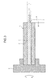
- FIG. 3 is a diagram illustrating an overview of lathe machining using the lathe machining member 1.
- the lathe machining member 1 is mounted on and fixed to a chuck 4 of a lathe, starts and keeps rotating the chuck 4 at a predetermined rotation speed, and moves a cutting tool 5 from the right side to the left side in the figure to cut the lathe machining member 1 into a desired shape.
- the lathe machining member 1 may further be subjected to the wire drawing process or the drawing process before the lathe machining member 1 is cut using the lathe.
- the maximum diameter R of the lathe machining member 1 after cutting by the cutting tool 5 is smaller than the diameter r of the core portion 3 (R ⁇ r).
- the diameter r of the core portion 3 is set to be larger than the maximum diameter R of the shape obtained by lathe machining, and the machined product consists of only a noble metal alloy.
- the diameter r is determined such that the maximum diameter of the shape obtained by machining becomes smaller than the diameter r of the core portion 3 regardless of the machined shape.
- the cylindrical core portion 3, at least a part of which is made of a noble metal alloy and which has the diameter larger than the maximum diameter of a shape obtained by lathe machining, and the hollow-cylindrical peripheral portion 2, which is made of a material different from the material of the core portion 3, are included. Further, the core portion 3 is arranged in the hollow portion of the peripheral portion 2 with no space. Therefore, most of a portion to be cut off by using the lathe can be made of a material other than the noble metal alloy. Consequently, when a rare and expensive material such as a noble metal alloy is used as a raw material for forming a machined product, it is possible to reduce waste of such material, enabling to reduce costs.
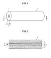
- FIG. 4 is a diagram illustrating a configuration of a lathe machining member according to a second embodiment of the present invention.
- FIG. 5 is a cross-sectional view taken along line B-B in FIG. 4 .
- a lathe machining member 6 illustrated in FIG. 4 and FIG. 5 includes a hollow-cylindrical peripheral portion 7 and a cylindrical core portion 8 that is arranged in a hollow portion of the peripheral portion 7 with no space.
- the peripheral portion 7 is made of the same material as that of the peripheral portion 2 of the first embodiment.
- the core portion 8 includes a hollow-cylindrical outer core portion 81 and an inner core portion 82 that is arranged in a hollow portion of the outer core portion 81 with no space.
- One of the outer core portion 81 and the inner core portion 82 is made of a noble metal alloy similarly to the core portion 3 described above, and the other is made of metal, such as cooper or aluminum, other than the noble metal alloy.
- a combination of the materials of the outer core portion 81 and the inner core portion 82 may be determined depending on intended end-usage of a machined product.
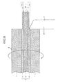
- FIG. 6 is a diagram illustrating an overview of lathe machining using the lathe machining member 6. Although it is not illustrated in FIG. 6 , a left end portion of the lathe machining member 6 in the figure is fixed to the chuck 4 similarly to FIG. 3 . Therefore, the lathe machining member 6 rotates along with the rotation of the chuck 4.
- the diameter r 1 of the core portion 8 i.e., the diameter r 1 of the outer core portion 81
- the diameter r 2 of the inner core portion 82 is set to be smaller than the maximum diameter R' (r 2 ⁇ R'). Accordingly, the machined product obtained by lathe machining has a two-layer structure formed of the outer core portion 81 and the inner core portion 82.
- the core portion 8 includes the outer core portion 81 and the inner core portion 82, which are made of mutually different metals (including a noble metal alloy), it is possible to combine optimal materials depending on use of the machined product.
- a multi-layer structure formed of more than two layers made of mutually different metals may be applied to the core portion instead of the two layers formed of the outer core portion and the inner core portion.
- the present invention is useful as a member to be mounted on a lathe to be lathe machined.
Landscapes
- Engineering & Computer Science (AREA)
- Mechanical Engineering (AREA)
- Turning (AREA)
Abstract
Description
- The present invention relates to a lathe machining member that is mounted on a lathe to be lathe machined.
- Conventionally, when metal or the like is machined by using a lathe, a work as a lathe machining member is mounted on and fixed to a chuck of the lathe and the work is cut by using a cutting tool or a drill to form a desired shape. Specifically, when an axisymmetric member such as a screw is formed by lathe machining, a solid cylindrical work made of a solid material is generally applied as the work (see, for example, Patent Literature 1).
-
- Patent Literature 1: Japanese Laid-open Patent Publication No.
2003-291002 - However, because a large part of the work is cut off by lathe machining, when a rare and expensive material such as a noble metal alloy is applied as a raw material, the material is wasted and it is difficult to reduce costs.
- The present invention has been made in view of the above, and it is an object of the present invention to provide a lathe machining member that, when forming a product made of a rare and expensive material by lathe machining, is capable of reducing waste of such material and reducing costs.
- To solve the problem described above and achieve the object, a lathe machining member according to the present invention that is mounted on a lathe to be lathe machined, includes: a cylindrical core portion, at least a part of which is made of a noble metal alloy and which has a diameter larger than a maximum diameter of a shape obtained by lathe machining; and a hollow-cylindrical peripheral portion made of a material different from the material of the core portion, wherein the core portion is arranged in a hollow portion of the peripheral portion with no space.
- The lathe machining member according to the invention as set forth in the invention described above, the core portion includes a hollow-cylindrical outer core portion; and an inner core portion that is arranged in a hollow portion of the outer core portion with no space, wherein one of the outer core portion and the inner core portion is made of the noble metal alloy and the other one of the outer core portion and the inner core portion is made of a material different from the noble metal alloy.
- The lathe machining member according to the invention as set forth in the invention described above, a diameter of the inner core portion is smaller than the maximum diameter.
- The lathe machining member according to the invention as set forth in the invention described above, the peripheral portion is made of an alloy material.
- The lathe machining member according to the invention as set forth in the invention described above, the alloy material is one material selected from the group consisting of copper-nickel silver, silver-copper alloy, brass, phosphor bronze, and beryllium copper.
- The lathe machining member according to the invention as set forth in the invention described above, the alloy material is one material selected from the group consisting of free-cutting brass, free-cutting phosphor bronze, free cutting nickel silver, and free-cutting beryllium copper.
- The lathe machining member according to the invention as set forth in the invention described above, the peripheral portion is made of iron.
- According to the present invention, a cylindrical core portion, at least a part of which is made of a noble metal alloy and which has a diameter larger than a maximum diameter of a shape obtained by lathe machining, and a hollow-cylindrical peripheral portion, which is made of a material different from the material of the core portion, are included. The core portion is arranged in a hollow portion of the peripheral portion with no space. Therefore, most of a portion to be cut off by using a lathe can be made of a material other than the noble metal alloy. Consequently, when a rare and expensive material such as noble metal alloy is used as a raw material for forming a machined product, it is possible to reduce waste of such material, enabling to reduce costs.
-
-
FIG. 1 is a diagram illustrating a configuration of a lathe machining member according to a first embodiment of the present invention. -
FIG. 2 is a cross-sectional view taken along line A-A inFIG. 1 . -
FIG. 3 is a diagram illustrating an overview of lathe machining using the lathe machining member according to the first embodiment of the present invention. -
FIG. 4 is a diagram illustrating a configuration of a lathe machining member according to a second embodiment of the present invention. -
FIG. 5 is a cross-sectional view taken along line B-B inFIG. 4 . -
FIG. 6 is a diagram illustrating an overview of lathe machining using the lathe machining member according to the second embodiment of the present invention. - Best modes for carrying out the present invention (hereinafter, "embodiments") are explained below with reference to the accompanying drawings.
-
FIG. 1 is a diagram illustrating a configuration of a lathe machining member according to a first embodiment of the present invention.FIG. 2 is a cross-sectional view taken along line A-A inFIG. 1 . Alathe machining member 1 includes a hollow-cylindricalperipheral portion 2 and acylindrical core portion 3 that is made of a material different from a material of theperipheral portion 2 and that is arranged in a hollow portion of theperipheral portion 2 with no space. - The
peripheral portion 2 is made of an alloy material. Any one material selected from a group of, for example, copper-nickel silver, silver-copper alloy, brass, phosphor bronze, and beryllium copper can be applied as the alloy material. Further, any one material (free-cutting material) selected from a group of, for example, free-cutting brass, free-cutting phosphor bronze, free cutting nickel silver, and free-cutting beryllium copper can be applied as the alloy material. A material other than the alloy material (for example, iron) may be applied to theperipheral portion 2. - The
core portion 3 is made of a noble metal alloy. For example, an alloy mainly consisting of silver (Ag), palladium (Pd), gold (Au), platinum (Pt), zinc (Zn), copper (Cu), iron (Fe), and nickel. (Ni), an alloy mainly consisting of palladium, silver, and copper, or an alloy mainly consisting of silver, platinum, zinc, gold, and copper may be applied as the noble metal alloy. Thelathe machining member 1 is formed by a wire drawing process or a drawing process such that a predetermined ratio is maintained between the diameter of theperipheral portion 2 and the diameter of thecore portion 3. -
FIG. 3 is a diagram illustrating an overview of lathe machining using thelathe machining member 1. When lathe machining is to be performed, thelathe machining member 1 is mounted on and fixed to achuck 4 of a lathe, starts and keeps rotating thechuck 4 at a predetermined rotation speed, and moves acutting tool 5 from the right side to the left side in the figure to cut thelathe machining member 1 into a desired shape. Thelathe machining member 1 may further be subjected to the wire drawing process or the drawing process before thelathe machining member 1 is cut using the lathe. - In
FIG. 3 , the maximum diameter R of thelathe machining member 1 after cutting by thecutting tool 5 is smaller than the diameter r of the core portion 3 (R<r).
In this manner, according to the first embodiment, the diameter r of thecore portion 3 is set to be larger than the maximum diameter R of the shape obtained by lathe machining, and the machined product consists of only a noble metal alloy. - Although a case is illustrated in
FIG. 3 in which a cylindrical shape is obtained by the cutting, this is by way of example only. That is, in the first embodiment, the diameter r is determined such that the maximum diameter of the shape obtained by machining becomes smaller than the diameter r of thecore portion 3 regardless of the machined shape. - According to the first embodiment of the present invention described above, the
cylindrical core portion 3, at least a part of which is made of a noble metal alloy and which has the diameter larger than the maximum diameter of a shape obtained by lathe machining, and the hollow-cylindricalperipheral portion 2, which is made of a material different from the material of thecore portion 3, are included. Further, thecore portion 3 is arranged in the hollow portion of theperipheral portion 2 with no space. Therefore, most of a portion to be cut off by using the lathe can be made of a material other than the noble metal alloy. Consequently, when a rare and expensive material such as a noble metal alloy is used as a raw material for forming a machined product, it is possible to reduce waste of such material, enabling to reduce costs. -
FIG. 4 is a diagram illustrating a configuration of a lathe machining member according to a second embodiment of the present invention.FIG. 5 is a cross-sectional view taken along line B-B inFIG. 4 . Alathe machining member 6 illustrated inFIG. 4 and FIG. 5 includes a hollow-cylindricalperipheral portion 7 and acylindrical core portion 8 that is arranged in a hollow portion of theperipheral portion 7 with no space. Theperipheral portion 7 is made of the same material as that of theperipheral portion 2 of the first embodiment. - The
core portion 8 includes a hollow-cylindricalouter core portion 81 and aninner core portion 82 that is arranged in a hollow portion of theouter core portion 81 with no space. One of theouter core portion 81 and theinner core portion 82 is made of a noble metal alloy similarly to thecore portion 3 described above, and the other is made of metal, such as cooper or aluminum, other than the noble metal alloy. A combination of the materials of theouter core portion 81 and theinner core portion 82 may be determined depending on intended end-usage of a machined product. -
FIG. 6 is a diagram illustrating an overview of lathe machining using thelathe machining member 6. Although it is not illustrated inFIG. 6 , a left end portion of thelathe machining member 6 in the figure is fixed to thechuck 4 similarly toFIG. 3 . Therefore, thelathe machining member 6 rotates along with the rotation of thechuck 4. - In
FIG. 6 , the diameter r1 of thecore portion 8, i.e., the diameter r1 of theouter core portion 81, is set to be larger than the maximum diameter R' of a shape to be obtained by lathe machining (r1>R'). The diameter r2 of theinner core portion 82 is set to be smaller than the maximum diameter R' (r2<R'). Accordingly, the machined product obtained by lathe machining has a two-layer structure formed of theouter core portion 81 and theinner core portion 82. - According to the second embodiment of the present invention described above, similarly to the first embodiment, when a rare and expensive material such as a noble metal alloy is used as a raw material for shaping a machined produce, it is possible to reduce waste of such material, enabling to reduce costs.
- Furthermore, according to the second embodiment of the present invention, because the
core portion 8 includes theouter core portion 81 and theinner core portion 82, which are made of mutually different metals (including a noble metal alloy), it is possible to combine optimal materials depending on use of the machined product. - In the second embodiment, a multi-layer structure formed of more than two layers made of mutually different metals may be applied to the core portion instead of the two layers formed of the outer core portion and the inner core portion.
- The embodiment is described above as best modes for carrying out the present invention; however, the present invention should not be limited to the above embodiment. The present invention can include various embodiments and the like not described herein. Further, various design changes and the like may be made in the range without departing from the technical idea as specified by the claims.
- As described above, the present invention is useful as a member to be mounted on a lathe to be lathe machined.
-
- 1, 6 LATHE MACHINING MEMBER
- 2, 7 PERIPHERAL PORTION
- 3, 8 CORE PORTION
- 4 CHUCK
- 5 CUTTING TOOL
- 81 OUTER CORE PORTION
- 82 INNER CORE PORTION
Claims (7)
- A lathe machining member that is mounted on a lathe to be lathe machined, the lathe machining member comprising:a cylindrical core portion, at least a part of which is made of a noble metal alloy and which has a diameter larger than a maximum diameter of a shape obtained by lathe machining; anda hollow-cylindrical peripheral portion made of a material different from the material of the core portion, whereinthe core portion is arranged in a hollow portion of the peripheral portion with no space.
- The lathe machining member according to claim 1, wherein
the core portion includes
a hollow-cylindrical outer core portion; and
an inner core portion that is arranged in a hollow portion of the outer core portion with no space, and wherein
one of the outer core portion and the inner core portion is made of the noble metal alloy and the other one of the outer core portion and the inner core portion is made of a material different from the noble metal alloy. - The lathe machining member according to claim 2, wherein
a diameter of the inner core portion is smaller than the maximum diameter. - The lathe machining member according to any one of claims 1 to 3, wherein
the peripheral portion is made of an alloy material. - The lathe machining member according to claim 4, wherein
the alloy material is one material selected from the group consisting of copper-nickel silver, silver-copper alloy, brass, phosphor bronze, and beryllium copper. - The lathe machining member according to claim 4, wherein
the alloy material is one material selected from the group consisting of free-cutting brass, free-cutting phosphor bronze, free cutting nickel silver, and free-cutting beryllium copper. - The lathe machining member according to any one of claims 1 to 3, wherein
the peripheral portion is made of iron.
Applications Claiming Priority (2)
| Application Number | Priority Date | Filing Date | Title |
|---|---|---|---|
| JP2008206239 | 2008-08-08 | ||
| PCT/JP2009/064141 WO2010016609A1 (en) | 2008-08-08 | 2009-08-10 | Member for lathe machining |
Publications (2)
| Publication Number | Publication Date |
|---|---|
| EP2311588A1 true EP2311588A1 (en) | 2011-04-20 |
| EP2311588A4 EP2311588A4 (en) | 2018-03-14 |
Family
ID=41663817
Family Applications (1)
| Application Number | Title | Priority Date | Filing Date |
|---|---|---|---|
| EP09805089.1A Withdrawn EP2311588A4 (en) | 2008-08-08 | 2009-08-10 | Member for lathe machining |
Country Status (6)
| Country | Link |
|---|---|
| US (1) | US9056355B2 (en) |
| EP (1) | EP2311588A4 (en) |
| JP (1) | JP5228049B2 (en) |
| KR (1) | KR20110025979A (en) |
| CN (1) | CN102105246B (en) |
| WO (1) | WO2010016609A1 (en) |
Cited By (1)
| Publication number | Priority date | Publication date | Assignee | Title |
|---|---|---|---|---|
| EP4292734A4 (en) * | 2021-02-09 | 2025-01-22 | Nanshin Co., Ltd | SEMI-FINISHED PIPE, METHOD FOR PRODUCING SEMI-FINISHED PIPE, PIPE AND METHOD FOR PRODUCING PIPE |
Families Citing this family (2)
| Publication number | Priority date | Publication date | Assignee | Title |
|---|---|---|---|---|
| TWI496652B (en) * | 2009-07-09 | 2015-08-21 | Citizen Holdings Co Ltd | Processing materials and holding institutions |
| WO2012005234A1 (en) * | 2010-07-05 | 2012-01-12 | 日本発條株式会社 | Member for processing with lathe, acicular member, and contact probe |
Family Cites Families (16)
| Publication number | Priority date | Publication date | Assignee | Title |
|---|---|---|---|---|
| US2196303A (en) * | 1939-02-21 | 1940-04-09 | Mallory & Co Inc P R | Silver copper alloy |
| US2527599A (en) * | 1946-11-30 | 1950-10-31 | Int Standard Electric Corp | Facsimile device |
| US2930115A (en) * | 1956-10-25 | 1960-03-29 | Sr Otto Dietzsch | Method of producing a modular body for controlled mixing or emission of a plurality of fluids |
| US2872899A (en) * | 1957-12-02 | 1959-02-10 | Trespalacios Basilio | Writing instrument |
| DE2253690B2 (en) * | 1972-11-02 | 1974-08-15 | Vereinigte Deutsche Metallwerke Ag, 6000 Frankfurt | Brass alloy with improved machinability |
| JPS5911386B2 (en) * | 1981-11-09 | 1984-03-15 | 株式会社中島銅工所 | Method of manufacturing solder chips |
| JPH05309538A (en) | 1992-05-11 | 1993-11-22 | Seiko Seiki Co Ltd | Machining method for pipe |
| JPH0784894B2 (en) * | 1992-08-03 | 1995-09-13 | 株式会社松澤製作所 | Seamless metal belt and method for manufacturing the same |
| JPH07275924A (en) * | 1994-03-31 | 1995-10-24 | Tokin Corp | Drawing method of TiPd alloy |
| JPH09267222A (en) * | 1996-04-01 | 1997-10-14 | Idemitsu Petrochem Co Ltd | Manufacture of seamless metallic belt |
| US6386423B1 (en) * | 1997-02-10 | 2002-05-14 | Delaware Capital Formation, Inc. | Soldering iron tips |
| JP4139520B2 (en) | 1999-06-08 | 2008-08-27 | Dowaホールディングス株式会社 | Work holding jig for machine tool and processing method |
| CN2485066Y (en) * | 2001-03-05 | 2002-04-10 | 华南理工大学 | Composite stainless steel bar with carbon steel core |
| JP2003291002A (en) | 2002-03-29 | 2003-10-14 | Ndc Co Ltd | Multi-purpose jig for turning machine |
| US7687156B2 (en) * | 2005-08-18 | 2010-03-30 | Tdy Industries, Inc. | Composite cutting inserts and methods of making the same |
| CN100496786C (en) * | 2007-09-07 | 2009-06-10 | 宝鸡市亚钛新金属有限公司 | Method for manufacturing titanium base composite pipe-rod materials |
-
2009
- 2009-08-10 EP EP09805089.1A patent/EP2311588A4/en not_active Withdrawn
- 2009-08-10 JP JP2010523916A patent/JP5228049B2/en active Active
- 2009-08-10 WO PCT/JP2009/064141 patent/WO2010016609A1/en not_active Ceased
- 2009-08-10 KR KR1020117001622A patent/KR20110025979A/en not_active Ceased
- 2009-08-10 US US12/737,555 patent/US9056355B2/en active Active
- 2009-08-10 CN CN2009801291355A patent/CN102105246B/en not_active Expired - Fee Related
Non-Patent Citations (1)
| Title |
|---|
| See references of WO2010016609A1 * |
Cited By (1)
| Publication number | Priority date | Publication date | Assignee | Title |
|---|---|---|---|---|
| EP4292734A4 (en) * | 2021-02-09 | 2025-01-22 | Nanshin Co., Ltd | SEMI-FINISHED PIPE, METHOD FOR PRODUCING SEMI-FINISHED PIPE, PIPE AND METHOD FOR PRODUCING PIPE |
Also Published As
| Publication number | Publication date |
|---|---|
| US9056355B2 (en) | 2015-06-16 |
| JPWO2010016609A1 (en) | 2012-01-26 |
| JP5228049B2 (en) | 2013-07-03 |
| CN102105246A (en) | 2011-06-22 |
| KR20110025979A (en) | 2011-03-14 |
| US20110123827A1 (en) | 2011-05-26 |
| EP2311588A4 (en) | 2018-03-14 |
| CN102105246B (en) | 2013-12-25 |
| WO2010016609A1 (en) | 2010-02-11 |
Similar Documents
| Publication | Publication Date | Title |
|---|---|---|
| US9056355B2 (en) | Lathe machining member | |
| EP2556911A1 (en) | Electrode wire for electro-discharge machining and method for manufacturing the same | |
| KR100837350B1 (en) | Electrode Wire for Wire Electric Discharge Machining | |
| EP1582602A3 (en) | Copper alloy and copper alloy manufacturing method | |
| EP1649950A3 (en) | Method for manufacturing copper alloys | |
| JP4416113B2 (en) | Diamond dies for special wire drawing | |
| MX2007003322A (en) | Copper-boron master alloy and its use in making silver-copper alloys. | |
| WO2002095082A3 (en) | Method of producing silver-copper alloys | |
| CN104400159A (en) | High-efficiency multilayer composite wire electrode | |
| KR100864910B1 (en) | Free Cutting Copper Alloy | |
| KR100864909B1 (en) | A free-cutting copper alloy | |
| JP2003039247A (en) | Electrode wire for electric discharge machining | |
| EP1080815A2 (en) | Wire electrode for electric-discharge machining | |
| JP3087552B2 (en) | Electrode wire for electric discharge machining | |
| JP2005329504A (en) | Electrode wire for wire electric discharge machining and electric discharge machined product manufactured using the same | |
| JP7210990B2 (en) | Method for producing amorphous alloy flakes | |
| JP2004292847A (en) | Aluminum alloy extruded material for machining, machined article made of aluminum alloy, and valve material for automotive part | |
| JP2004330352A (en) | Electrode wire for wire electric discharge machining and surface modification method using the same | |
| JP3319271B2 (en) | Electrode wire for electric discharge machining | |
| JPH06106420A (en) | Electrode wire for electric discharge machining | |
| CN1509487A (en) | A tripping armature for a magnetic release | |
| JPS634619B2 (en) | ||
| JPH11347847A (en) | Electrode wire for wire electric discharge machining | |
| WO2004074526A3 (en) | Copper alloy and use thereof for cast moulding | |
| JP4089551B2 (en) | High-strength wire EDM electrode wire |
Legal Events
| Date | Code | Title | Description |
|---|---|---|---|
| PUAI | Public reference made under article 153(3) epc to a published international application that has entered the european phase |
Free format text: ORIGINAL CODE: 0009012 |
|
| 17P | Request for examination filed |
Effective date: 20110201 |
|
| AK | Designated contracting states |
Kind code of ref document: A1 Designated state(s): AT BE BG CH CY CZ DE DK EE ES FI FR GB GR HR HU IE IS IT LI LT LU LV MC MK MT NL NO PL PT RO SE SI SK SM TR |
|
| AX | Request for extension of the european patent |
Extension state: AL BA RS |
|
| DAX | Request for extension of the european patent (deleted) | ||
| RA4 | Supplementary search report drawn up and despatched (corrected) |
Effective date: 20180213 |
|
| RIC1 | Information provided on ipc code assigned before grant |
Ipc: B23Q 3/08 20060101ALI20180208BHEP Ipc: B23Q 3/06 20060101ALI20180208BHEP Ipc: B21C 1/00 20060101ALI20180208BHEP Ipc: B23B 1/00 20060101AFI20180208BHEP |
|
| STAA | Information on the status of an ep patent application or granted ep patent |
Free format text: STATUS: THE APPLICATION IS DEEMED TO BE WITHDRAWN |
|
| 18D | Application deemed to be withdrawn |
Effective date: 20180913 |