EP2310262B1 - Integrally ribbed rogallo wing array - Google Patents
Integrally ribbed rogallo wing array Download PDFInfo
- Publication number
- EP2310262B1 EP2310262B1 EP09797311.9A EP09797311A EP2310262B1 EP 2310262 B1 EP2310262 B1 EP 2310262B1 EP 09797311 A EP09797311 A EP 09797311A EP 2310262 B1 EP2310262 B1 EP 2310262B1
- Authority
- EP
- European Patent Office
- Prior art keywords
- wings
- rogallo
- wing
- sheet
- wind energy
- Prior art date
- Legal status (The legal status is an assumption and is not a legal conclusion. Google has not performed a legal analysis and makes no representation as to the accuracy of the status listed.)
- Active
Links
Images


Classifications
-
- A—HUMAN NECESSITIES
- A63—SPORTS; GAMES; AMUSEMENTS
- A63H—TOYS, e.g. TOPS, DOLLS, HOOPS OR BUILDING BLOCKS
- A63H27/00—Toy aircraft; Other flying toys
- A63H27/02—Model aircraft
-
- F—MECHANICAL ENGINEERING; LIGHTING; HEATING; WEAPONS; BLASTING
- F03—MACHINES OR ENGINES FOR LIQUIDS; WIND, SPRING, OR WEIGHT MOTORS; PRODUCING MECHANICAL POWER OR A REACTIVE PROPULSIVE THRUST, NOT OTHERWISE PROVIDED FOR
- F03D—WIND MOTORS
- F03D13/00—Assembly, mounting or commissioning of wind motors; Arrangements specially adapted for transporting wind motor components
- F03D13/20—Arrangements for mounting or supporting wind motors; Masts or towers for wind motors
-
- F—MECHANICAL ENGINEERING; LIGHTING; HEATING; WEAPONS; BLASTING
- F05—INDEXING SCHEMES RELATING TO ENGINES OR PUMPS IN VARIOUS SUBCLASSES OF CLASSES F01-F04
- F05B—INDEXING SCHEME RELATING TO WIND, SPRING, WEIGHT, INERTIA OR LIKE MOTORS, TO MACHINES OR ENGINES FOR LIQUIDS COVERED BY SUBCLASSES F03B, F03D AND F03G
- F05B2240/00—Components
- F05B2240/40—Use of a multiplicity of similar components
-
- F—MECHANICAL ENGINEERING; LIGHTING; HEATING; WEAPONS; BLASTING
- F05—INDEXING SCHEMES RELATING TO ENGINES OR PUMPS IN VARIOUS SUBCLASSES OF CLASSES F01-F04
- F05B—INDEXING SCHEME RELATING TO WIND, SPRING, WEIGHT, INERTIA OR LIKE MOTORS, TO MACHINES OR ENGINES FOR LIQUIDS COVERED BY SUBCLASSES F03B, F03D AND F03G
- F05B2240/00—Components
- F05B2240/90—Mounting on supporting structures or systems
- F05B2240/92—Mounting on supporting structures or systems on an airbourne structure
- F05B2240/921—Mounting on supporting structures or systems on an airbourne structure kept aloft due to aerodynamic effects
-
- Y—GENERAL TAGGING OF NEW TECHNOLOGICAL DEVELOPMENTS; GENERAL TAGGING OF CROSS-SECTIONAL TECHNOLOGIES SPANNING OVER SEVERAL SECTIONS OF THE IPC; TECHNICAL SUBJECTS COVERED BY FORMER USPC CROSS-REFERENCE ART COLLECTIONS [XRACs] AND DIGESTS
- Y02—TECHNOLOGIES OR APPLICATIONS FOR MITIGATION OR ADAPTATION AGAINST CLIMATE CHANGE
- Y02E—REDUCTION OF GREENHOUSE GAS [GHG] EMISSIONS, RELATED TO ENERGY GENERATION, TRANSMISSION OR DISTRIBUTION
- Y02E10/00—Energy generation through renewable energy sources
- Y02E10/70—Wind energy
- Y02E10/72—Wind turbines with rotation axis in wind direction
-
- Y—GENERAL TAGGING OF NEW TECHNOLOGICAL DEVELOPMENTS; GENERAL TAGGING OF CROSS-SECTIONAL TECHNOLOGIES SPANNING OVER SEVERAL SECTIONS OF THE IPC; TECHNICAL SUBJECTS COVERED BY FORMER USPC CROSS-REFERENCE ART COLLECTIONS [XRACs] AND DIGESTS
- Y02—TECHNOLOGIES OR APPLICATIONS FOR MITIGATION OR ADAPTATION AGAINST CLIMATE CHANGE
- Y02E—REDUCTION OF GREENHOUSE GAS [GHG] EMISSIONS, RELATED TO ENERGY GENERATION, TRANSMISSION OR DISTRIBUTION
- Y02E10/00—Energy generation through renewable energy sources
- Y02E10/70—Wind energy
- Y02E10/728—Onshore wind turbines
Definitions
- This relates to the technical field of Rogallo wings.
- a conventional aircraft wing has an upper skin and a lower skin, and is usually made from metal. Due to the two skins, a conventional aircraft wing may be too heavy for certain applications and is more difficult to construct than a wing formed from a single skin. A conventional aircraft wing can be prohibitively expensive and too time consuming to be advantageously used in some applications, such as for example in wind turbines.
- a traditional Rogallo wing is formed from a conical single sail-fabric connected between various supporting ribs.
- the Rogallo wing is the type of wing that was used in early hang gliders and is now most commonly seen in kids' kites.
- the Rogallo wing is a simpler design than a conventional aircraft wing, but requires more maintenance and has a shorter life-span than a conventional aircraft wing.
- DE 196 45 415 A1 discloses a generator with a rotor or impeller, and a funnel-shaped nozzle-like sail in front of it, to increase the intake area of the generator. The sail is maintained in inflated condition due to the angle of incidence between it and the wind flow.
- Anchoring cables have varying anchoring points, which are used to change size, expansion, shape, and position of the sail during operation.
- EP 1 359 320 A1 discloses a device for extracting energy from a fluid flow passing in a first direction, comprising at least one turbine embedded in the fluid flow, the fluid flow maintaining a pressure difference between the input end of the turbine and the output end of the turbine; the turbine being at least partially shielded by a flow shroud means; said flow shroud means effecting an increase of said pressure difference by causing a partial area of the cross section of the total fluid flow to bypass the turbine; the bypassing flow being deflected by said flow shroud means into a second direction different from the first direction; and said flow shroud means consisting of at least one flow shroud means element shaped like a sail or similar means.
- WO 00/75507 discloses a diffuser augmented fluid-driven turbine for recovering energy from a fluid stream comprising: fluid-driven rotor blades contained in a housing; two support ring assemblies positioned on either side of the housing and axially mounted with respect to the blades; a tensioned fabric shroud extending between rings of the support ring assemblies; and, a spar assembly that extends longitudinally to the blades and which is adjustably mounted to the rings of the support ring assemblies.
- the spar assembly has a passage through which fluid upstream of the rotor blades can be injected into a diffuser section of the turbine without having to pass through the blades.
- the turbine is supported by a tower.
- a wind energy extraction apparatus comprising the features of claim 1.
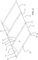
- Figs. 1 - 3 show Rogallo wings 10.
- the Rogallo wing 10 has an aerodynamic sheet 12 that has a leading end 14 and a trailing edge 16.
- the leading end 14 may be for example, as shown in Fig. 1 , a leading edge, which may be flat for example. In other embodiments, the leading end may be a point. In some embodiments, the leading end 14 has a shorter length than the trailing end 16.
- the trailing edge 16 is curved to form a sheet of increasing concavity away from the leading edge 14. The concavity may be increased for example gradually, or in steps or other suitable configurations.
- At least two folded edges 18, 20 extend between the leading edge 14 and the trailing edge 16 on opposed sides of the aerodynamic sheet 12.
- the two folded edges 18, 20 act as integral ribs of the Rogallo wing 10.
- the Rogallo wing has a pan shape, in which the wing has a leading edge 14 that is not curved and a trailing edge 16 that is curved.
- curved may mean, for example, stepped, bent, or any type of concave shape.
- the integral ribs 18, 20 effectively form external ribs of the Rogallo wing.
- the integral ribs help prevent the structure of the wings from bending when air pressure, such as wind, is applied against the wings.
- the increasing concavity between the leading edge 14 and the trailing edge 16 also imparts significant strength to the wing panel.
- the combination of the increasing concavity and the integral ribs together give the required strength to the wing panel to prevent the force of the wind from permanently deforming the external ribs of the wing panels in a storm or very strong wind.
- the type, strength and thickness of the material used also have an effect on the strength of the wing panel.
- the Rogallo wing 10 may have a hollow end 22 at the leading edge 14 of the aerodynamic sheet 12.
- Hollow end 22 may extend at least partially along the leading edge 14.
- Hollow end 22 may be formed by, for example, at least one ring or eyelet on leading edge 14. The rings or eyelets may be aligned, for example.
- the hollow end 22 may be formed by folding the leading edge 14 back on itself.
- a loop may be attached to each of the two folded edges 18, 20. Loops 24, 26 lie on the folded edges 18, 20 adjacent to the trailing edge 16 of the aerodynamic sheet 12. A wire may be connected through the loops 24, 26 on each of the folded edges.
- the wire may be, for example a first supporting cable 30 that supports the trailing edge 16 of the aerodynamic sheet by passing through the loops 24, 26.
- a wire is disposed through the hollow ends 22 of each of the leading edges 14 of the array of interconnected wings 10.
- the wire may be, for example, a second supporting cable 32, second supporting cable 32 extending through the hollow ends 22 of the leading edge 14 of the Rogallo wings 10. Adjacent folded edges of adjacent wings may be connected together, by for example rivets 28 that connect the folded edge 20 of one Rogallo wing 10 with the folded edge 18 of an adjacent Rogallo wing.
- each folded edge is formed by folding wing 10 once and then optionally folding the formed folded edge portion over top of itself one or more times to give the desired thickness.
- the folded edge 18 may be formed by, or reinforced with, a structural angle of metal or other material connected to wing 10. Structural angles are generally formed by extrusion processes, and may be connected to wing 10 by riveting.
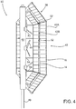
- support fins 52 are used to support an array 38 of interconnected Rogallo wings 10.
- Each of the arrays 38 of Rogallo wings may be supported by cables between supporting fins 52.
- the cables may further comprise at least first supporting cable 30 and second supporting cable 32, the Rogallo wings being supported between first supporting cable 30 and second supporting cable 32 ( Fig. 2 ).
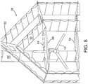
- the Rogallo wings are shown in operation with a turbine 50.
- a plurality of Rogallo wings may form the wing members of turbine 50.
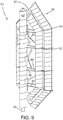
- the embodiment illustrated shows a wind energy extraction apparatus comprising one or more concentrator wings 42.
- the concentrator wings 42 comprise Rogallo wings and react with a flow of wind to induce a drop in static air pressure that is then used to drive one or more impellors 44 and one or more power converters 72 shown encased in housing and connected to the one or more impellors 44.
- Arrays 38 of Rogallo wings are supported on support fins 52 connected to a fuselage 62.
- the fuselage 62 is supported on a support pole 40.
- Each array 38 of Rogallo wings 10 acts as a concentrator wing 42.
- braces 64, 66 are shown supporting the support fins 52.
- Braces 64 connect the support fins 52 to the fuselage 62.
- Braces 66 connect between support fins 52 lying on opposed sides of the fuselage 62.
- a supporting brace 70 may connect the brace 66 to the fuselage 62 for additional support.
- Fig. 7 shows a corner support fin 52 supported by braces 62, 64.
- Fig. 8 shows a support fin 52 connected directly to the top of the fuselage 62.
- the Rogallo wings 10 may be made, for example, from aluminum sheeting with one material thickness. In the embodiments shown, the Rogallo wings have no internal ribs.
- the aerodynamic shape of the wing is created by having a relatively flat leading edge, developing into a pronounced bow shape at the trailing edge of the wing.
- the aerodynamic sheet replicates the curvature of a conventional wing, but instead uses only one sheet of material. To a point, increasing the degree of bow in the trailing edge of a Rogallo type wing is equivalent to increasing the curvature of a conventional wing.
- the Rogallo wings 10 may be constructed from a single flat sheet of material.
- the material may be curved into a Rogallo wing shape and then have the edges folded and bent to create an integral or external rib.
- the leading and trailing edges 14, 16 may be supported by cables 30, 32.
- stiff members such as rods or pipes may be used to support the Rogallo wings.
- Other materials other than aluminum may be used to construct the aerodynamic sheets 12.
- a variety of materials may be used to form the aerodynamic sheets, although factors such as the cost of tooling the materials and level of degradation of the materials due to sun exposure may be considered when choosing a new design, depending on budgetary concerns and whether the wings are to be used in an indoor or outdoor setting.
- Metals, composites, fiberglass materials and synthetics are examples of types of materials that may be used to form the aerodynamic sheets. Stiff materials are preferable due to their longer life-span and reduced maintenance.
- the arrays 38 ( Fig. 4 ) of Rogallo wings 10 may be installed as a group, using two cables 30, 32 ( Fig. 2 ), one running at the leading edge 14 and one at the trailing edge 16.
- the wing may then be installed between two rigid structures, such as the support fins 52 shown in Fig. 4 .
- the use of cables adds to the flexibility of the wings, so that the wings can flex to a degree without damaging the individual Rogallo wing panels.
- the Rogallo wings have the advantages and simplicity of sailcloth wings but also may be made using durable materials, such as aluminum, to give long life and good durability.
- the integrals ribs give the aerodynamic sheet structure and form, which allow the wings to be made without internal ribs. In some embodiments internal ribs may be used to give additional support.
- the adjacent folded edges of adjacent Rogallo wings may be connected by means other than rivets 28 shown in Fig. 2 .
- cables alone may join the individual Rogallo wings together without additional supporting structures.
- the adjacent folded edges of the Rogallo wings may be connected by other means such as bolts and screws, or the folded edges may be welded together.
- Concentrator wings 42 operate fundamentally the same as aircraft wings.
- the concentrator wings 42 are arrays 38 of Rogallo wings 10.
- each of the Rogallo wings 10 have a first surface 58 that is convex shaped at the trailing edge 16 to accelerate the flow of wind, and a corresponding second surface 60 that is concave shaped on the opposite side of the aerodynamic sheet at the trailing edge 16 that tends to slightly decelerate the flow of wind past the second surface 60.
- first and second concentrator wings 42A and 42B may operate in series to enhance the pressure differential effect created as wind travels over surfaces 58 and 60 ( Fig. 1 ).
- first and second concentrator wings 42A and 42B may be staggered, for example.
- First concentrator wing 42A induces a lower static pressure region over the first surfaces 58 of the wing that in turn causes an acceleration of the wind flow past the second surfaces 60 of an adjacent second concentrator wing 42B. This in turn causes an increased acceleration of the flow of wind over the first surfaces 58 of the second concentrator wing 42B.
- the accelerated flow is used to increase the static pressure differential occurring between opposed sides of the impellors 44.
- the static pressure gradient between the opposed sides of the impellor 44 causes the wind to be focused more powerfully to drive impellors 44 and power converters 72.
- the Rogallo wing arrays may be used in different turbine designs.
- a turbine may have a single drive impellor 44 connected to a single power converter 72.
- a single row of concentrator wings 42 may draw wind across the impellors 44.
- the turbine 50 may be connected directly to a power utility pole and be arranged so that power is provided to the utility power.
Landscapes
- Engineering & Computer Science (AREA)
- Life Sciences & Earth Sciences (AREA)
- Sustainable Development (AREA)
- Sustainable Energy (AREA)
- Chemical & Material Sciences (AREA)
- Combustion & Propulsion (AREA)
- Mechanical Engineering (AREA)
- General Engineering & Computer Science (AREA)
- Wind Motors (AREA)
Applications Claiming Priority (3)
| Application Number | Priority Date | Filing Date | Title |
|---|---|---|---|
| CA2638229A CA2638229C (en) | 2008-07-17 | 2008-07-17 | Integrally ribbed rogallo wing array |
| US12/181,095 US8358027B2 (en) | 2008-07-28 | 2008-07-28 | Integrally ribbed Rogallo wing array |
| PCT/CA2009/000976 WO2010006427A1 (en) | 2008-07-17 | 2009-07-16 | Integrally ribbed rogallo wing array |
Publications (3)
| Publication Number | Publication Date |
|---|---|
| EP2310262A1 EP2310262A1 (en) | 2011-04-20 |
| EP2310262A4 EP2310262A4 (en) | 2013-08-21 |
| EP2310262B1 true EP2310262B1 (en) | 2018-03-14 |
Family
ID=41549963
Family Applications (1)
| Application Number | Title | Priority Date | Filing Date |
|---|---|---|---|
| EP09797311.9A Active EP2310262B1 (en) | 2008-07-17 | 2009-07-16 | Integrally ribbed rogallo wing array |
Country Status (4)
| Country | Link |
|---|---|
| EP (1) | EP2310262B1 (enExample) |
| JP (1) | JP5546538B2 (enExample) |
| AU (1) | AU2009270298B2 (enExample) |
| WO (1) | WO2010006427A1 (enExample) |
Families Citing this family (2)
| Publication number | Priority date | Publication date | Assignee | Title |
|---|---|---|---|---|
| PL402206A1 (pl) * | 2012-12-21 | 2014-06-23 | Witold Maziarz | Układ kierownic silnika wiatrowego |
| FR3007581A1 (fr) | 2013-06-20 | 2014-12-26 | Innogur Technologies | Plateforme photovoltaique flottante et installation autonome de traitement de l'eau associee a une telle plateforme |
Family Cites Families (12)
| Publication number | Priority date | Publication date | Assignee | Title |
|---|---|---|---|---|
| US3135483A (en) * | 1962-08-20 | 1964-06-02 | Ryan Aeronautical Co | Auxiliary boom control system for rogallo type wing aircraft |
| FR2376792A1 (fr) * | 1977-01-05 | 1978-08-04 | Lemoigne Pierre | Aile volante perfectionnee |
| SE430529B (sv) * | 1982-12-30 | 1983-11-21 | Vindkraft Goeteborg Kb | Anordning vid vindturbiner |
| US5620153A (en) * | 1995-03-20 | 1997-04-15 | Ginsberg; Harold M. | Light aircraft with inflatable parachute wing propelled by a ducted propeller |
| US5884863A (en) * | 1995-10-26 | 1999-03-23 | United Technologies Corporation | Method and apparatus for deploying a wing |
| DE19645415A1 (de) * | 1996-11-04 | 1998-05-07 | Paul Dipl Ing Kramer | Strömungskraftwerk |
| AUPQ085299A0 (en) | 1999-06-08 | 1999-07-01 | Smith, Bruce Justin | Diffuser augmented wind turbine |
| US20030042366A1 (en) * | 2001-09-04 | 2003-03-06 | Britt Karl D. | Kite structure |
| EP1359320A1 (en) | 2002-04-10 | 2003-11-05 | Hans Grassmann | Shrouded fluid flow turbine |
| US7220096B2 (en) * | 2004-03-16 | 2007-05-22 | Tocher Angus J | Habitat friendly, multiple impellor, wind energy extraction |
| AU2005263138C1 (en) * | 2004-07-16 | 2011-11-03 | Angus J. Tocher | Wind energy extraction system |
| JP2006214302A (ja) * | 2005-02-02 | 2006-08-17 | Nova Kenkyusho:Kk | 風車装置 |
-
2009
- 2009-07-16 AU AU2009270298A patent/AU2009270298B2/en not_active Ceased
- 2009-07-16 EP EP09797311.9A patent/EP2310262B1/en active Active
- 2009-07-16 JP JP2011517722A patent/JP5546538B2/ja active Active
- 2009-07-16 WO PCT/CA2009/000976 patent/WO2010006427A1/en not_active Ceased
Non-Patent Citations (1)
| Title |
|---|
| None * |
Also Published As
| Publication number | Publication date |
|---|---|
| JP2011528077A (ja) | 2011-11-10 |
| WO2010006427A1 (en) | 2010-01-21 |
| JP5546538B2 (ja) | 2014-07-09 |
| AU2009270298A1 (en) | 2010-01-21 |
| EP2310262A1 (en) | 2011-04-20 |
| EP2310262A4 (en) | 2013-08-21 |
| AU2009270298B2 (en) | 2014-06-05 |
Similar Documents
| Publication | Publication Date | Title |
|---|---|---|
| CN106065845B (zh) | 用于风轮机转子叶片的空气流构造 | |
| US4045144A (en) | Wind energy concentrators | |
| EP2694805B1 (en) | Diffuser augmented wind turbines | |
| EP2699796B1 (en) | Diffuser augmented wind turbines | |
| US9523279B2 (en) | Rotor blade fence for a wind turbine | |
| US9140233B2 (en) | Wind power generation system | |
| CN101446263A (zh) | 风力涡轮机叶片加强件 | |
| US20160290314A1 (en) | Wind turbine blade with wave shaped trailing edge | |
| EP3177838B1 (en) | Fluid-redirecting structure | |
| EP2740929A2 (en) | Wind blades with mechanical elements for pretensioning in tension fabrics | |
| CN110892149A (zh) | 用于风力涡轮转子叶片的气流构造 | |
| EP2310262B1 (en) | Integrally ribbed rogallo wing array | |
| WO2007038836A1 (en) | Wind turbine | |
| US8358027B2 (en) | Integrally ribbed Rogallo wing array | |
| US12098697B2 (en) | Method and apparatus for constructing a ringed airfoil | |
| CA2638229C (en) | Integrally ribbed rogallo wing array | |
| CA2628855A1 (en) | Vertical multiple blade turbine | |
| RU2807846C1 (ru) | Ветряк парусный горизонтальный конический | |
| US20130266438A1 (en) | Ring airfoil with parallel inner and outer surfaces | |
| JP2011528077A5 (enExample) | ||
| EP4656875A1 (en) | Wind turbine | |
| WO2024232786A1 (ru) | Ветряк парусный, горизонтальный, конический. | |
| WO2024193779A1 (en) | A pitch controlled wind turbine | |
| GB2630973A (en) | A wind turbine blade assembly | |
| EP2851557A1 (en) | A wind turbine blade with root end aerodynamic flaps |
Legal Events
| Date | Code | Title | Description |
|---|---|---|---|
| PUAI | Public reference made under article 153(3) epc to a published international application that has entered the european phase |
Free format text: ORIGINAL CODE: 0009012 |
|
| 17P | Request for examination filed |
Effective date: 20110208 |
|
| AK | Designated contracting states |
Kind code of ref document: A1 Designated state(s): AT BE BG CH CY CZ DE DK EE ES FI FR GB GR HR HU IE IS IT LI LT LU LV MC MK MT NL NO PL PT RO SE SI SK SM TR |
|
| AX | Request for extension of the european patent |
Extension state: AL BA RS |
|
| DAX | Request for extension of the european patent (deleted) | ||
| A4 | Supplementary search report drawn up and despatched |
Effective date: 20130722 |
|
| RIC1 | Information provided on ipc code assigned before grant |
Ipc: A63H 27/18 20060101ALI20130716BHEP Ipc: F03D 1/04 20060101ALI20130716BHEP Ipc: B64C 3/00 20060101ALI20130716BHEP Ipc: F03D 1/02 20060101ALI20130716BHEP Ipc: B64C 3/26 20060101AFI20130716BHEP |
|
| 17Q | First examination report despatched |
Effective date: 20150528 |
|
| GRAP | Despatch of communication of intention to grant a patent |
Free format text: ORIGINAL CODE: EPIDOSNIGR1 |
|
| INTG | Intention to grant announced |
Effective date: 20171004 |
|
| GRAS | Grant fee paid |
Free format text: ORIGINAL CODE: EPIDOSNIGR3 |
|
| GRAA | (expected) grant |
Free format text: ORIGINAL CODE: 0009210 |
|
| AK | Designated contracting states |
Kind code of ref document: B1 Designated state(s): AT BE BG CH CY CZ DE DK EE ES FI FR GB GR HR HU IE IS IT LI LT LU LV MC MK MT NL NO PL PT RO SE SI SK SM TR |
|
| REG | Reference to a national code |
Ref country code: GB Ref legal event code: FG4D |
|
| REG | Reference to a national code |
Ref country code: CH Ref legal event code: EP Ref country code: AT Ref legal event code: REF Ref document number: 978621 Country of ref document: AT Kind code of ref document: T Effective date: 20180315 |
|
| REG | Reference to a national code |
Ref country code: IE Ref legal event code: FG4D |
|
| REG | Reference to a national code |
Ref country code: DE Ref legal event code: R096 Ref document number: 602009051262 Country of ref document: DE |
|
| REG | Reference to a national code |
Ref country code: NL Ref legal event code: MP Effective date: 20180314 |
|
| REG | Reference to a national code |
Ref country code: LT Ref legal event code: MG4D |
|
| PG25 | Lapsed in a contracting state [announced via postgrant information from national office to epo] |
Ref country code: ES Free format text: LAPSE BECAUSE OF FAILURE TO SUBMIT A TRANSLATION OF THE DESCRIPTION OR TO PAY THE FEE WITHIN THE PRESCRIBED TIME-LIMIT Effective date: 20180314 Ref country code: HR Free format text: LAPSE BECAUSE OF FAILURE TO SUBMIT A TRANSLATION OF THE DESCRIPTION OR TO PAY THE FEE WITHIN THE PRESCRIBED TIME-LIMIT Effective date: 20180314 Ref country code: NO Free format text: LAPSE BECAUSE OF FAILURE TO SUBMIT A TRANSLATION OF THE DESCRIPTION OR TO PAY THE FEE WITHIN THE PRESCRIBED TIME-LIMIT Effective date: 20180614 Ref country code: FI Free format text: LAPSE BECAUSE OF FAILURE TO SUBMIT A TRANSLATION OF THE DESCRIPTION OR TO PAY THE FEE WITHIN THE PRESCRIBED TIME-LIMIT Effective date: 20180314 Ref country code: LT Free format text: LAPSE BECAUSE OF FAILURE TO SUBMIT A TRANSLATION OF THE DESCRIPTION OR TO PAY THE FEE WITHIN THE PRESCRIBED TIME-LIMIT Effective date: 20180314 Ref country code: CY Free format text: LAPSE BECAUSE OF FAILURE TO SUBMIT A TRANSLATION OF THE DESCRIPTION OR TO PAY THE FEE WITHIN THE PRESCRIBED TIME-LIMIT Effective date: 20180314 |
|
| REG | Reference to a national code |
Ref country code: AT Ref legal event code: MK05 Ref document number: 978621 Country of ref document: AT Kind code of ref document: T Effective date: 20180314 |
|
| PG25 | Lapsed in a contracting state [announced via postgrant information from national office to epo] |
Ref country code: SE Free format text: LAPSE BECAUSE OF FAILURE TO SUBMIT A TRANSLATION OF THE DESCRIPTION OR TO PAY THE FEE WITHIN THE PRESCRIBED TIME-LIMIT Effective date: 20180314 Ref country code: LV Free format text: LAPSE BECAUSE OF FAILURE TO SUBMIT A TRANSLATION OF THE DESCRIPTION OR TO PAY THE FEE WITHIN THE PRESCRIBED TIME-LIMIT Effective date: 20180314 Ref country code: GR Free format text: LAPSE BECAUSE OF FAILURE TO SUBMIT A TRANSLATION OF THE DESCRIPTION OR TO PAY THE FEE WITHIN THE PRESCRIBED TIME-LIMIT Effective date: 20180615 Ref country code: BG Free format text: LAPSE BECAUSE OF FAILURE TO SUBMIT A TRANSLATION OF THE DESCRIPTION OR TO PAY THE FEE WITHIN THE PRESCRIBED TIME-LIMIT Effective date: 20180614 |
|
| PG25 | Lapsed in a contracting state [announced via postgrant information from national office to epo] |
Ref country code: RO Free format text: LAPSE BECAUSE OF FAILURE TO SUBMIT A TRANSLATION OF THE DESCRIPTION OR TO PAY THE FEE WITHIN THE PRESCRIBED TIME-LIMIT Effective date: 20180314 Ref country code: IT Free format text: LAPSE BECAUSE OF FAILURE TO SUBMIT A TRANSLATION OF THE DESCRIPTION OR TO PAY THE FEE WITHIN THE PRESCRIBED TIME-LIMIT Effective date: 20180314 Ref country code: EE Free format text: LAPSE BECAUSE OF FAILURE TO SUBMIT A TRANSLATION OF THE DESCRIPTION OR TO PAY THE FEE WITHIN THE PRESCRIBED TIME-LIMIT Effective date: 20180314 Ref country code: NL Free format text: LAPSE BECAUSE OF FAILURE TO SUBMIT A TRANSLATION OF THE DESCRIPTION OR TO PAY THE FEE WITHIN THE PRESCRIBED TIME-LIMIT Effective date: 20180314 Ref country code: PL Free format text: LAPSE BECAUSE OF FAILURE TO SUBMIT A TRANSLATION OF THE DESCRIPTION OR TO PAY THE FEE WITHIN THE PRESCRIBED TIME-LIMIT Effective date: 20180314 |
|
| PG25 | Lapsed in a contracting state [announced via postgrant information from national office to epo] |
Ref country code: CZ Free format text: LAPSE BECAUSE OF FAILURE TO SUBMIT A TRANSLATION OF THE DESCRIPTION OR TO PAY THE FEE WITHIN THE PRESCRIBED TIME-LIMIT Effective date: 20180314 Ref country code: SK Free format text: LAPSE BECAUSE OF FAILURE TO SUBMIT A TRANSLATION OF THE DESCRIPTION OR TO PAY THE FEE WITHIN THE PRESCRIBED TIME-LIMIT Effective date: 20180314 Ref country code: SM Free format text: LAPSE BECAUSE OF FAILURE TO SUBMIT A TRANSLATION OF THE DESCRIPTION OR TO PAY THE FEE WITHIN THE PRESCRIBED TIME-LIMIT Effective date: 20180314 Ref country code: AT Free format text: LAPSE BECAUSE OF FAILURE TO SUBMIT A TRANSLATION OF THE DESCRIPTION OR TO PAY THE FEE WITHIN THE PRESCRIBED TIME-LIMIT Effective date: 20180314 |
|
| REG | Reference to a national code |
Ref country code: DE Ref legal event code: R097 Ref document number: 602009051262 Country of ref document: DE |
|
| PG25 | Lapsed in a contracting state [announced via postgrant information from national office to epo] |
Ref country code: PT Free format text: LAPSE BECAUSE OF FAILURE TO SUBMIT A TRANSLATION OF THE DESCRIPTION OR TO PAY THE FEE WITHIN THE PRESCRIBED TIME-LIMIT Effective date: 20180716 |
|
| PLBE | No opposition filed within time limit |
Free format text: ORIGINAL CODE: 0009261 |
|
| STAA | Information on the status of an ep patent application or granted ep patent |
Free format text: STATUS: NO OPPOSITION FILED WITHIN TIME LIMIT |
|
| PG25 | Lapsed in a contracting state [announced via postgrant information from national office to epo] |
Ref country code: DK Free format text: LAPSE BECAUSE OF FAILURE TO SUBMIT A TRANSLATION OF THE DESCRIPTION OR TO PAY THE FEE WITHIN THE PRESCRIBED TIME-LIMIT Effective date: 20180314 |
|
| 26N | No opposition filed |
Effective date: 20181217 |
|
| PG25 | Lapsed in a contracting state [announced via postgrant information from national office to epo] |
Ref country code: SI Free format text: LAPSE BECAUSE OF FAILURE TO SUBMIT A TRANSLATION OF THE DESCRIPTION OR TO PAY THE FEE WITHIN THE PRESCRIBED TIME-LIMIT Effective date: 20180314 |
|
| REG | Reference to a national code |
Ref country code: CH Ref legal event code: PL |
|
| PG25 | Lapsed in a contracting state [announced via postgrant information from national office to epo] |
Ref country code: MC Free format text: LAPSE BECAUSE OF FAILURE TO SUBMIT A TRANSLATION OF THE DESCRIPTION OR TO PAY THE FEE WITHIN THE PRESCRIBED TIME-LIMIT Effective date: 20180314 Ref country code: LU Free format text: LAPSE BECAUSE OF NON-PAYMENT OF DUE FEES Effective date: 20180716 |
|
| REG | Reference to a national code |
Ref country code: BE Ref legal event code: MM Effective date: 20180731 |
|
| PG25 | Lapsed in a contracting state [announced via postgrant information from national office to epo] |
Ref country code: FR Free format text: LAPSE BECAUSE OF NON-PAYMENT OF DUE FEES Effective date: 20180731 Ref country code: LI Free format text: LAPSE BECAUSE OF NON-PAYMENT OF DUE FEES Effective date: 20180731 Ref country code: CH Free format text: LAPSE BECAUSE OF NON-PAYMENT OF DUE FEES Effective date: 20180731 |
|
| PG25 | Lapsed in a contracting state [announced via postgrant information from national office to epo] |
Ref country code: BE Free format text: LAPSE BECAUSE OF NON-PAYMENT OF DUE FEES Effective date: 20180731 |
|
| PG25 | Lapsed in a contracting state [announced via postgrant information from national office to epo] |
Ref country code: MT Free format text: LAPSE BECAUSE OF NON-PAYMENT OF DUE FEES Effective date: 20180716 |
|
| PG25 | Lapsed in a contracting state [announced via postgrant information from national office to epo] |
Ref country code: TR Free format text: LAPSE BECAUSE OF FAILURE TO SUBMIT A TRANSLATION OF THE DESCRIPTION OR TO PAY THE FEE WITHIN THE PRESCRIBED TIME-LIMIT Effective date: 20180314 |
|
| PG25 | Lapsed in a contracting state [announced via postgrant information from national office to epo] |
Ref country code: HU Free format text: LAPSE BECAUSE OF FAILURE TO SUBMIT A TRANSLATION OF THE DESCRIPTION OR TO PAY THE FEE WITHIN THE PRESCRIBED TIME-LIMIT; INVALID AB INITIO Effective date: 20090716 |
|
| PG25 | Lapsed in a contracting state [announced via postgrant information from national office to epo] |
Ref country code: MK Free format text: LAPSE BECAUSE OF NON-PAYMENT OF DUE FEES Effective date: 20180314 |
|
| PG25 | Lapsed in a contracting state [announced via postgrant information from national office to epo] |
Ref country code: IS Free format text: LAPSE BECAUSE OF FAILURE TO SUBMIT A TRANSLATION OF THE DESCRIPTION OR TO PAY THE FEE WITHIN THE PRESCRIBED TIME-LIMIT Effective date: 20180714 |
|
| PGFP | Annual fee paid to national office [announced via postgrant information from national office to epo] |
Ref country code: DE Payment date: 20210720 Year of fee payment: 13 |
|
| REG | Reference to a national code |
Ref country code: DE Ref legal event code: R119 Ref document number: 602009051262 Country of ref document: DE |
|
| PG25 | Lapsed in a contracting state [announced via postgrant information from national office to epo] |
Ref country code: DE Free format text: LAPSE BECAUSE OF NON-PAYMENT OF DUE FEES Effective date: 20230201 |
|
| P01 | Opt-out of the competence of the unified patent court (upc) registered |
Effective date: 20230420 |
|
| PGFP | Annual fee paid to national office [announced via postgrant information from national office to epo] |
Ref country code: GB Payment date: 20250618 Year of fee payment: 17 |
|
| PGFP | Annual fee paid to national office [announced via postgrant information from national office to epo] |
Ref country code: IE Payment date: 20250618 Year of fee payment: 17 |