EP2309901B1 - Device for heating and/or frothing milk for machines for preparing hot beverages such as a cappuccino - Google Patents
Device for heating and/or frothing milk for machines for preparing hot beverages such as a cappuccino Download PDFInfo
- Publication number
- EP2309901B1 EP2309901B1 EP08761365A EP08761365A EP2309901B1 EP 2309901 B1 EP2309901 B1 EP 2309901B1 EP 08761365 A EP08761365 A EP 08761365A EP 08761365 A EP08761365 A EP 08761365A EP 2309901 B1 EP2309901 B1 EP 2309901B1
- Authority
- EP
- European Patent Office
- Prior art keywords
- milk
- mixing chamber
- air
- tubular body
- steam
- Prior art date
- Legal status (The legal status is an assumption and is not a legal conclusion. Google has not performed a legal analysis and makes no representation as to the accuracy of the status listed.)
- Active
Links
Images


Classifications
-
- A—HUMAN NECESSITIES
- A47—FURNITURE; DOMESTIC ARTICLES OR APPLIANCES; COFFEE MILLS; SPICE MILLS; SUCTION CLEANERS IN GENERAL
- A47J—KITCHEN EQUIPMENT; COFFEE MILLS; SPICE MILLS; APPARATUS FOR MAKING BEVERAGES
- A47J31/00—Apparatus for making beverages
- A47J31/44—Parts or details or accessories of beverage-making apparatus
- A47J31/4485—Nozzles dispensing heated and foamed milk, i.e. milk is sucked from a milk container, heated and foamed inside the device, and subsequently dispensed from the nozzle
-
- A—HUMAN NECESSITIES
- A47—FURNITURE; DOMESTIC ARTICLES OR APPLIANCES; COFFEE MILLS; SPICE MILLS; SUCTION CLEANERS IN GENERAL
- A47J—KITCHEN EQUIPMENT; COFFEE MILLS; SPICE MILLS; APPARATUS FOR MAKING BEVERAGES
- A47J31/00—Apparatus for making beverages
- A47J31/44—Parts or details or accessories of beverage-making apparatus
- A47J31/46—Dispensing spouts, pumps, drain valves or like liquid transporting devices
Definitions
- the present invention relates to a device for heating and/or frothing milk to prepare hot beverages such as a cappuccino.
- coffee making machines are provided with a device for dispensing steam at high temperature, by means of which milk is heated and/or frothed in order to prepare hot beverages, such as for example a cappuccino or a warm milk.
- this device In the jargon of the field, this device is known as frother.
- Known frothers comprise a tubular element in which the inlet end is associated with a source of steam at high temperature, and the outlet end is provided with a nozzle for dispensing the steam.
- known frothers comprise a tap for blocking and adjusting the flow of steam, which is provided with an actuation knob.
- an operator manually arranges the tubular element inside a container, such as a cup, jug or the like, which contains cold milk, and places the nozzle below or at the free surface of the milk, depending on whether he wishes to heat it or also froth it, i.e., produce a surface layer of foam.
- a container such as a cup, jug or the like, which contains cold milk
- the nozzle below or at the free surface of the milk, depending on whether he wishes to heat it or also froth it, i.e., produce a surface layer of foam.
- the operator then opens the tap and adjusts it according to his own sensibility in order to obtain in output from the nozzle a flow of steam which is suitable for the situation.
- the operator opens and closes the tap repeatedly as he simultaneously moves the container of the milk toward and away from the nozzle, so that the flow of steam incorporates air to form the foam.
- DE 10 2005 010599 discloses a device for heating and/or frothing milk, with a single tube for the supply of air and milk.
- EP 0 344 859 discloses a device for frothing and heating milk for beverages, wherein the air is sucked at the output, after the milk and vapor are mixed.
- the aim of the present invention is to devise a device for heating and/or frothing milk for machines for preparing hot beverages such as a cappuccino, whose operation is regular, constant and independent of the sensibility and experience of an operator, thus allowing to obtain milk which is warmed and/or frothed to a preset degree.
- An object of the present invention is to devise a device for heating and/or frothing milk which is versatile and flexible in use and can be installed easily on any machine for making hot beverages without requiring particular modifications or interventions for adaptation.
- Still another object of the present invention is to provide a device for heating and/or frothing milk which can be cleaned easily so as to ensure a high degree of hygiene.
- Another object of the present invention is to provide a device which is simple, relatively easy to provide in practice, safe in use, effective in operation, and relatively low in cost.
- the device according to the invention also comprises an ambient air supply duct, which has an intake port adapted to be connected to the outside environment and a port for introducing the air in the mixing chamber, the air being drawn into the mixing chamber due to the partial vacuum created by the flow of steam between the converging portion and the diverging portion of the Venturi tube.
- the device according to the invention comprises a tap which is associated with the air supply duct for opening and closing the air intake port.
- the reference numeral 1 generally designates a device for heating and/or frothing milk for machines for preparing hot beverages such as cappuccino.
- the device 1 comprises a tubular body 2, inside which a Venturi tube is provided which comprises an intake end 3, a converging portion 4, a diverging portion 5 and a discharge end 6.
- the intake end 3 can be associated with a source of steam, such as for example a boiler, a pressurized boiler, an instant heat exchanger (Thermoblock).
- a source of steam such as for example a boiler, a pressurized boiler, an instant heat exchanger (Thermoblock).
- the flow of steam passes through the Venturi tube along the direction indicated by the arrow F.
- a chamber 7 for mixing the milk with the steam and optionally with air drawn from outside.
- the device 1 further comprises at least one milk supply duct 8, which has a drawing port 9 which can be associated with a milk reservoir, not shown, and a milk input port 10, which leads into the mixing chamber 7.
- the milk is drawn from the reservoir into the mixing chamber 7 due to the partial vacuum created by the acceleration of the flow of steam between the converging portion 4 and the diverging portion 5.
- the device 1 comprises at least one duct 11 for supplying air from the outside environment, which has an intake port 12 adapted to be connected to the outside environment and an air input port 13 which leads into the mixing chamber 7.
- the air is drawn from the outside into the mixing chamber 7 due to the partial vacuum created by the acceleration of the flow of steam between the converging portion 4 and the diverging portion 5.
- a dispenser 14 for the milk heated and/or frothed in the mixing chamber 7 is associated with the end of the tubular body 2 at which the discharge end 6 of the Venturi tube leads out.
- a chamber 15 for compacting the heated and/or frothed milk that exits from the mixing chamber 7 is defined between the diverging portion 5 and the dispenser 14.
- the milk supply duct 8 and the air supply duct 11 are connected to the tubular body 2 and are arranged substantially perpendicular to the longitudinal axis of the Venturi tube and are mutually offset with respect to the direction of the flow of steam.
- the milk input port 10 is offset backwardly with respect to the air input port 13.
- the mixing chamber 7 is defined by a cylindrical portion 7a, which is formed inside the tubular body 2 and is hollow and coaxial with respect to the Venturi tube, and by two surfaces 7b and 7c which are substantially frustum-shaped and face each other, so as to be opposite one another, within the cylindrical portion 7a.
- the two frustum-shaped surfaces 7b and 7c are arranged substantially coaxially to the cylindrical portion 7a and their respective smaller end faces are mutually juxtaposed and adjacent at a preset distance D.
- the milk input port 10 and the air input port 13 are provided at the lateral surface of the cylindrical portion 7a.
- the smaller end faces of the two mutually juxtaposed frustum-shaped surfaces 7b and 7c define the region at which the aspirated milk and air meet.
- the annular volume that lies at the peripheral portion of such region defines the space within which, due to turbulent motions, the milk is frothed by the air, forming foam.
- the Venturi tube comprises a first tubular portion 16, which connects the converging portion 4 to the mixing chamber 7, and a second tubular portion 17, which connects the mixing chamber 7 to the diverging portion 5.
- the first tubular portion 16 and the second tubular portion 17 are substantially coaxial, and the first portion has a smaller inside diameter than the second portion.
- the discharge end of the first tubular portion 16 and the intake end of the second tubular portion 17 are provided at the smaller end faces of the two frustum-shaped surfaces 7b and 7c which are mutually juxtaposed.
- the intake end 3, the converging portion 4 and the first tubular portion 16 of the Venturi tube are provided in a nozzle 18.
- the nozzle 18 has an end which is inserted detachably within the tubular body 2 with the interposition of sealing rings 19 and an opposite end which protrudes from the tubular body 2 and is provided with means for coupling or engagement with a machine for preparing hot beverages.
- the end of the nozzle 18 that is inserted within the tubular body 2 is frustum-shaped, so as to define the frustum-shaped surface 7b.
- the other frustum-shaped surface 7c is instead defined on one face of a partition which is formed within the tubular body 2 and is crossed by the second tubular portion 17.
- the diverging portion 5 is provided on the opposite face of such partition.
- the dispenser 14 is associated detachably with the tubular body 2 and comprises an internal cavity 20 which defines, in association with the tubular body 2, the compaction chamber 15 and is connected to a channel 21 for the outflow of the warmed and/or frothed milk.
- the outflow channel 21 is crossed by at least one longitudinal fin 22, which improves the flow of milk in output, contributing to give a "cream" effect to the frothed milk.
- Both the nozzle 18 and the dispenser 14 are coupled to the tubular body 2 by interlocking coupling or other temporary couplings which are known to the person skilled in the art.
- both the nozzle 18 and the dispenser 14 have an end which can be inserted substantially snugly within a corresponding open end of the tubular body 2, reference notches or tabs being further provided.
- the device 1 further comprises a tap 23, which is associated with the air supply duct 11 to open and close the air intake port 12.
- the tap 23 is of the "open/close” type; i.e., it assumes two configurations: an open configuration, in which the air intake port 12 is connected to the outside environment, and a closure configuration, in which the air intake port 12 is isolated with respect to the outside environment.
- the tap 23 could be replaced by any suitable air regulator elements or electrovalve.
- the air is aspirated into the mixing chamber 7 due to the partial vacuum created by the acceleration of the flow of steam in the converging portion 4 of the Venturi tube, so that the milk drawn into the mixing chamber 7, in addition to being heated by the steam, is also emulsified with the aspirated air and thus frothed, forming foam.
- any inflow of air into the mixing chamber 7 is prevented, so that the milk drawn into the mixing chamber 7 is only heated by the steam and is not also frothed.
- the tap 23 comprises a cup-shaped element 24, which is coupled rotatably to the end of the air supply duct 11, where the intake port 12 is provided, a gasket 25 being interposed between the cup-shaped element 24 and the air supply duct 11.
- a recess 28 is formed on the outer lateral surface of the air supply duct 11 and is connected to the interspace 26.
- an actuation handwheel 29 is provided, which is adapted to facilitate grip and handling by an operator.
- the cup-shaped element 24 turns between the open configuration and the closed configuration.
- the hole 27 engages the recess 28, so that the air can flow into the mixing chamber 7 along the path defined by the hole 27, by the interspace 26 and by the air supply duct 11.
- Means are also provided for stopping the rotation of the cup-shaped element 24 in the open configuration and in the closed configuration.
- These stop means comprise at least one tooth 30 which protrudes from the cup-shaped element 24 and is accommodated so that it can slide within a groove 31 defined in the tubular body 2, an abutment surface 32 and 33 of the tooth 30 being defined at each of the two opposite ends of the groove 31 in order to stop the cup-shaped element 24 respectively in the closed configuration and in the open configuration.
- the device 1 is applied to any machine for making hot beverages which has a high-temperature steam source; this application is facilitated by the coupling or insertion means provided at the end of the nozzle 18.
- the source of steam is connected to the intake end 3, while the milk supply duct 8 is connected, by means of a tube inserted therein, to a milk reservoir or container.
- the tap 23 is arranged in the closed configuration, in which the hole 27 does not engage the recess 28, preventing the inflow of air from the outside to the inside of the mixing chamber 7.
- the milk thus aspirated combines with the steam and warms up, and after passing through the compaction chamber 15 is dispensed through the outflow channel 21 of the dispenser 14.
- the partial vacuum generated by the acceleration that the flow of steam undergoes in passing through the converging portion 4 is such as to draw into the mixing chamber 7 not only the milk but also air.
- the milk thus frothed and heated passes through the compaction chamber 15, where it compacts again, to be then dispensed through the outflow channel 21 of the dispenser 14.
- the operations for cleaning the device 1 are particularly simple and effective; it is in fact sufficient to draw water instead of milk through the supply duct 8 in order to obtain, due to the heat of the flow of steam, the complete removal of any residue of milk and of any particle of dirt.
- the device according to the invention in fact allows to obtain warm and/or frothed milk at a degree and a level which are constant and independent of the sensibility and experience of the operator.
- the device according to the invention is simple to use and does not require particular manual skill of the operator; it is in fact sufficient to turn the tap in one of the two positions to obtain either warm milk or warm and frothed milk.
- the device according to the invention is flexible and versatile in use; it can in fact be applied to any machine without particular constructive constraints and without requiring particular structural modifications, and it can also operate arranged in any orientation.
- the device according to the invention ensures a high degree of hygiene and sterilization.
Landscapes
- Engineering & Computer Science (AREA)
- Food Science & Technology (AREA)
- Apparatus For Making Beverages (AREA)
Abstract
Description
- The present invention relates to a device for heating and/or frothing milk to prepare hot beverages such as a cappuccino.
- It is known that coffee making machines are provided with a device for dispensing steam at high temperature, by means of which milk is heated and/or frothed in order to prepare hot beverages, such as for example a cappuccino or a warm milk.
- In the jargon of the field, this device is known as frother.
- Known frothers comprise a tubular element in which the inlet end is associated with a source of steam at high temperature, and the outlet end is provided with a nozzle for dispensing the steam.
- Moreover, known frothers comprise a tap for blocking and adjusting the flow of steam, which is provided with an actuation knob.
- In use, an operator manually arranges the tubular element inside a container, such as a cup, jug or the like, which contains cold milk, and places the nozzle below or at the free surface of the milk, depending on whether he wishes to heat it or also froth it, i.e., produce a surface layer of foam.
- The operator then opens the tap and adjusts it according to his own sensibility in order to obtain in output from the nozzle a flow of steam which is suitable for the situation. In particular, in order to obtain frothed milk, the operator opens and closes the tap repeatedly as he simultaneously moves the container of the milk toward and away from the nozzle, so that the flow of steam incorporates air to form the foam.
- These known frothers, however, suffer drawbacks, among which it is necessary to note that the production of warm milk or frothed milk depends on the sensibility and experience that the operator has in arranging the nozzle at the correct level and in adjusting the degree of opening of the tap.
- Another drawback of known frothers consists in that they work with the tubular element arranged vertically or at most obliquely, and this forces design and manufacturing constraints of the machines to which they are applied.
- Another drawback of known frothers consists in that residues of milk and dirt accumulate on the outer surface of the tubular element and of the nozzle and must be removed manually with the aid of sponges and washing liquids. However, these operations do not ensure a high and safe degree of hygiene, so that harmful bacterial colonies can grow from the residues of milk and dirt.
-
DE 10 2005 010599 discloses a device for heating and/or frothing milk, with a single tube for the supply of air and milk. -
EP 0 344 859 discloses a device for frothing and heating milk for beverages, wherein the air is sucked at the output, after the milk and vapor are mixed. - The aim of the present invention is to devise a device for heating and/or frothing milk for machines for preparing hot beverages such as a cappuccino, whose operation is regular, constant and independent of the sensibility and experience of an operator, thus allowing to obtain milk which is warmed and/or frothed to a preset degree.
- An object of the present invention is to devise a device for heating and/or frothing milk which is versatile and flexible in use and can be installed easily on any machine for making hot beverages without requiring particular modifications or interventions for adaptation.
- Still another object of the present invention is to provide a device for heating and/or frothing milk which can be cleaned easily so as to ensure a high degree of hygiene.
- Within this aim, another object of the present invention is to provide a device which is simple, relatively easy to provide in practice, safe in use, effective in operation, and relatively low in cost.
- This aim and these and other objects are all achieved by the present device for heating and/or frothing milk for machines for preparing hot beverages such as cappuccino, as defined in
claim 1. - In a preferred embodiment, the device according to the invention also comprises an ambient air supply duct, which has an intake port adapted to be connected to the outside environment and a port for introducing the air in the mixing chamber, the air being drawn into the mixing chamber due to the partial vacuum created by the flow of steam between the converging portion and the diverging portion of the Venturi tube.
- In another preferred embodiment, the device according to the invention comprises a tap which is associated with the air supply duct for opening and closing the air intake port.
- Further characteristics and advantages of the present invention will become better apparent from the detailed description of a preferred but not exclusive embodiment of a device for heating and/or frothing milk for machines for making hot beverages such as cappuccino, according to the invention, illustrated by way of non-limiting example in the accompanying drawings, wherein:
-
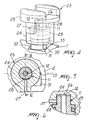
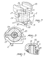
Figure 1 is an exploded perspective view of the device according to the invention; -
Figure 2 is a general perspective view of the device according to the invention; -
Figure 3 is a sectional view of the device according to the invention, taken along the central longitudinal plane; -
Figure 4 is an enlarged-scale view of the air supply duct of the device according to the invention with the tap in the open configuration; -
Figure 5 is a sectional view, taken along a plane which is perpendicular to the longitudinal axis of the air supply duct; -
Figure 6 is a sectional view, taken along the line VI-VI ofFigure 5 ; -
Figures 7, 8 and 9 correspond toFigures 4, 5 and 6 , but with the tap in the closed configuration. - With reference to the figures, the
reference numeral 1 generally designates a device for heating and/or frothing milk for machines for preparing hot beverages such as cappuccino. - In the present description, the term "substantially" is used with a meaning of "correspondence" within tolerances which are known to the person skilled in the art.
- The
device 1 comprises atubular body 2, inside which a Venturi tube is provided which comprises anintake end 3, a convergingportion 4, a divergingportion 5 and adischarge end 6. - The
intake end 3 can be associated with a source of steam, such as for example a boiler, a pressurized boiler, an instant heat exchanger (Thermoblock). - The flow of steam passes through the Venturi tube along the direction indicated by the arrow F.
- Between the converging
portion 4 and the divergingportion 5 there is a chamber 7 for mixing the milk with the steam and optionally with air drawn from outside. - The
device 1 further comprises at least onemilk supply duct 8, which has adrawing port 9 which can be associated with a milk reservoir, not shown, and amilk input port 10, which leads into the mixing chamber 7. - The milk is drawn from the reservoir into the mixing chamber 7 due to the partial vacuum created by the acceleration of the flow of steam between the
converging portion 4 and thediverging portion 5. - Moreover, the
device 1 comprises at least oneduct 11 for supplying air from the outside environment, which has anintake port 12 adapted to be connected to the outside environment and anair input port 13 which leads into the mixing chamber 7. - In this case also, the air is drawn from the outside into the mixing chamber 7 due to the partial vacuum created by the acceleration of the flow of steam between the
converging portion 4 and the divergingportion 5. - A
dispenser 14 for the milk heated and/or frothed in the mixing chamber 7 is associated with the end of thetubular body 2 at which thedischarge end 6 of the Venturi tube leads out. - A
chamber 15 for compacting the heated and/or frothed milk that exits from the mixing chamber 7 is defined between the divergingportion 5 and thedispenser 14. - The
milk supply duct 8 and theair supply duct 11 are connected to thetubular body 2 and are arranged substantially perpendicular to the longitudinal axis of the Venturi tube and are mutually offset with respect to the direction of the flow of steam. - In particular, the
milk input port 10 is offset backwardly with respect to theair input port 13. - The mixing chamber 7 is defined by a cylindrical portion 7a, which is formed inside the
tubular body 2 and is hollow and coaxial with respect to the Venturi tube, and by twosurfaces 7b and 7c which are substantially frustum-shaped and face each other, so as to be opposite one another, within the cylindrical portion 7a. - The two frustum-
shaped surfaces 7b and 7c are arranged substantially coaxially to the cylindrical portion 7a and their respective smaller end faces are mutually juxtaposed and adjacent at a preset distance D. - The
milk input port 10 and theair input port 13 are provided at the lateral surface of the cylindrical portion 7a. - The smaller end faces of the two mutually juxtaposed frustum-
shaped surfaces 7b and 7c define the region at which the aspirated milk and air meet. - The annular volume that lies at the peripheral portion of such region defines the space within which, due to turbulent motions, the milk is frothed by the air, forming foam.
- The Venturi tube comprises a first
tubular portion 16, which connects theconverging portion 4 to the mixing chamber 7, and a secondtubular portion 17, which connects the mixing chamber 7 to thediverging portion 5. - The first
tubular portion 16 and the secondtubular portion 17 are substantially coaxial, and the first portion has a smaller inside diameter than the second portion. - The discharge end of the first
tubular portion 16 and the intake end of the secondtubular portion 17 are provided at the smaller end faces of the two frustum-shaped surfaces 7b and 7c which are mutually juxtaposed. - In the embodiment shown in the accompanying figures, the
intake end 3, theconverging portion 4 and the firsttubular portion 16 of the Venturi tube are provided in anozzle 18. - The
nozzle 18 has an end which is inserted detachably within thetubular body 2 with the interposition ofsealing rings 19 and an opposite end which protrudes from thetubular body 2 and is provided with means for coupling or engagement with a machine for preparing hot beverages. - The end of the
nozzle 18 that is inserted within thetubular body 2 is frustum-shaped, so as to define the frustum-shaped surface 7b. - The other frustum-
shaped surface 7c is instead defined on one face of a partition which is formed within thetubular body 2 and is crossed by the secondtubular portion 17. - The diverging
portion 5 is provided on the opposite face of such partition. - The
dispenser 14 is associated detachably with thetubular body 2 and comprises aninternal cavity 20 which defines, in association with thetubular body 2, thecompaction chamber 15 and is connected to achannel 21 for the outflow of the warmed and/or frothed milk. - The
outflow channel 21 is crossed by at least onelongitudinal fin 22, which improves the flow of milk in output, contributing to give a "cream" effect to the frothed milk. - Both the
nozzle 18 and thedispenser 14 are coupled to thetubular body 2 by interlocking coupling or other temporary couplings which are known to the person skilled in the art. In particular, both thenozzle 18 and thedispenser 14 have an end which can be inserted substantially snugly within a corresponding open end of thetubular body 2, reference notches or tabs being further provided. - The
device 1 further comprises atap 23, which is associated with theair supply duct 11 to open and close theair intake port 12. - The
tap 23 is of the "open/close" type; i.e., it assumes two configurations: an open configuration, in which theair intake port 12 is connected to the outside environment, and a closure configuration, in which theair intake port 12 is isolated with respect to the outside environment. - The
tap 23 could be replaced by any suitable air regulator elements or electrovalve. - In the open configuration, the air is aspirated into the mixing chamber 7 due to the partial vacuum created by the acceleration of the flow of steam in the converging
portion 4 of the Venturi tube, so that the milk drawn into the mixing chamber 7, in addition to being heated by the steam, is also emulsified with the aspirated air and thus frothed, forming foam. - In the closed configuration, any inflow of air into the mixing chamber 7 is prevented, so that the milk drawn into the mixing chamber 7 is only heated by the steam and is not also frothed.
- In the embodiment shown in the accompanying figures, the
tap 23 comprises a cup-shapedelement 24, which is coupled rotatably to the end of theair supply duct 11, where theintake port 12 is provided, agasket 25 being interposed between the cup-shapedelement 24 and theair supply duct 11. - Between the bottom of the cup-shaped
element 24 and the end of theair supply duct 11 there is aninterspace 26, while the wall of the cup-shapedelement 24 is crossed by a throughhole 27 which is perpendicular to theair supply duct 11. - A
recess 28 is formed on the outer lateral surface of theair supply duct 11 and is connected to theinterspace 26. - Conveniently, at the upper end of the cup-shaped
element 24 anactuation handwheel 29 is provided, which is adapted to facilitate grip and handling by an operator. - The cup-shaped
element 24 turns between the open configuration and the closed configuration. - In the open configuration (
Figures 4-6 ), thehole 27 engages therecess 28, so that the air can flow into the mixing chamber 7 along the path defined by thehole 27, by theinterspace 26 and by theair supply duct 11. - In the closed configuration (
Figures 7-9 ), in which the cup-shapedelement 24 is rotated through an angle of 90° with respect to the open configuration, thehole 27 is excluded from therecess 28, thus preventing the inflow of the air from outside to theintake port 12. - Means are also provided for stopping the rotation of the cup-shaped
element 24 in the open configuration and in the closed configuration. - These stop means comprise at least one
tooth 30 which protrudes from the cup-shapedelement 24 and is accommodated so that it can slide within agroove 31 defined in thetubular body 2, anabutment surface tooth 30 being defined at each of the two opposite ends of thegroove 31 in order to stop the cup-shapedelement 24 respectively in the closed configuration and in the open configuration. - Operation of the device according to the invention is as follows.
- The
device 1 is applied to any machine for making hot beverages which has a high-temperature steam source; this application is facilitated by the coupling or insertion means provided at the end of thenozzle 18. - The source of steam is connected to the
intake end 3, while themilk supply duct 8 is connected, by means of a tube inserted therein, to a milk reservoir or container. - If one wishes to prepare warm milk without froth, the
tap 23 is arranged in the closed configuration, in which thehole 27 does not engage therecess 28, preventing the inflow of air from the outside to the inside of the mixing chamber 7. - In this configuration, the flow of steam that passes through the Venturi tube undergoes, in passing through the converging
portion 4, such an acceleration as to create a partial vacuum which is sufficient to draw the milk into the mixing chamber 7. - The milk thus aspirated combines with the steam and warms up, and after passing through the
compaction chamber 15 is dispensed through theoutflow channel 21 of thedispenser 14. - If one wishes to obtain frothed warm milk, i.e., with foam, it is sufficient to turn the
tap 23 through 90° and move it to the open configuration, in which thehole 27 engages therecess 28, connecting theair supply duct 11 to the outside environment. - In this case, the partial vacuum generated by the acceleration that the flow of steam undergoes in passing through the converging
portion 4 is such as to draw into the mixing chamber 7 not only the milk but also air. - The milk and the air mix with the steam, forming foam. The milk thus frothed and heated passes through the
compaction chamber 15, where it compacts again, to be then dispensed through theoutflow channel 21 of thedispenser 14. - It is noted that the operations for cleaning the
device 1 are particularly simple and effective; it is in fact sufficient to draw water instead of milk through thesupply duct 8 in order to obtain, due to the heat of the flow of steam, the complete removal of any residue of milk and of any particle of dirt. - Moreover, it is noted that no residues of milk accumulate on the outside of the
device 1; the heating and frothing of the milk in fact occur inside thedevice 1. - In practice it has been found that the described invention achieves the proposed aim and objects.
- The device according to the invention in fact allows to obtain warm and/or frothed milk at a degree and a level which are constant and independent of the sensibility and experience of the operator.
- The device according to the invention is simple to use and does not require particular manual skill of the operator; it is in fact sufficient to turn the tap in one of the two positions to obtain either warm milk or warm and frothed milk.
- Moreover, the device according to the invention is flexible and versatile in use; it can in fact be applied to any machine without particular constructive constraints and without requiring particular structural modifications, and it can also operate arranged in any orientation.
- Finally, the device according to the invention ensures a high degree of hygiene and sterilization.
- The invention thus conceived is susceptible of numerous modifications and variations, all of which are within the scope of the appended claims.
- All the details may further be replaced with other technically equivalent ones.
- In practice, the materials used, as well as the shapes and the dimensions, may be any according to requirements without thereby abandoning the scope of the protection of the appended claims.
- Where technical features mentioned in any claim are followed by reference signs, those reference signs have been included for the sole purpose of increasing the intelligibility of the claims and accordingly, such reference signs do not have any limiting effect on the interpretation of each element identified by way of example by such reference signs.
Claims (20)
- A device (1) for heating and/or frothing milk for machines for preparing hot beverages such as cappuccino, comprising a tubular body (2) inside which there is a Venturi effect tube, which has an intake end (3) which can be associated with a source of steam and a discharge end (6), a mixing chamber, (7) which is defined between the converging portion (4) and the diverging portion (5) of said Venturi tube, and at least one milk supply duct (8), which has a drawing port (9) which can be associated with a milk reservoir and a port (10) for introducing the milk in said mixing chamber (7), the milk being drawn into said mixing chamber (7) due to the partial vacuum created by the flow of steam between said converging portion (4) and said diverging portion (5), characterized in that said mixing chamber (7) is defined by a cylindrical portion (7a), which is hollow and substantially coaxial to said Venturi effect tube, and by two surfaces (7b, 7c) which are substantially frustum-shaped and face the inside of said cylindrical portion and are arranged coaxially thereto and so that their respective smaller end faces are mutually juxtaposed and adjacent at a preset distance (D), said two frustum-shaped surfaces (7b, 7c) defiling two cone portions with the vertexes that face one another.
- The device according to claim 1, characterized in that it comprises at least one duct (11) for supplying ambient air which has an intake port (12) connected to the outside environment and an input port (13) for introducing the air in said mixing chamber (7), the air being drawn into said mixing chamber due to the partial vacuum created by the flow of said steam between said converging portion (4) and said diverging portion (5).
- The device according to claim 1 or 2, characterized in that it comprises a dispenser (14) of the milk that has been heated and/or frothed in said mixing chamber (7), which is associated with said tubular body (2) downstream, in the direction of the flow of said steam, of said discharge end (6) of the Venturi effect tube.
- The device according to claim 3, characterized in that it comprises a chamber (15) for compacting the heated and/or frothed milk, which is defined between said diverging portion (5) and said dispenser (14).
- The device according to claim 1, characterized in that said milk input port (10) is provided on the lateral surface of said cylindrical portion (7a).
- The device according to claim 1 and according to one or more of claims 2 to 4, characterized in that said air input port (12) is provided on the lateral surface of said cylindrical portion (7a).
- The device according to one or more of claims 2 to 6, characterized in that said milk input port (10) is offset backwardly with respect to said air input port (12) relative to the direction of flow of the steam.
- The device according to one or more of claims 2 to 7, characterized in that said milk supply duct (8) and said air supply duct (11) are connected to said tubular body (2) and are arranged substantially at right angles to said Venturi effect tube.
- The device according to one or more of the preceding claims, characterized in that said Venturi effect tube comprises a first tubular portion (16) which connects said converging portion (4) to said mixing chamber (7) and a second tubular portion (17) which connects said mixing chamber (7) to said diverging portion (5), said first tubular portion (16) and said second tubular portion (17) being substantially coaxial.
- The device according to claim 9, characterized in that said first tubular portion (16) has an inside diameter which is smaller than the inside diameter of said second tubular portion (17).
- The device according to claim 9 or 10, characterized in that said intake end (3), said converging portion (4) and said fust tubular portion (16) of the Venturi effect tube are defined in a nozzle (18) which has an end inserted detachably in said tubular body (2) and an opposite end which protrudes from said tubular body (2) and is provided with means for coupling to a machine for preparing hot beverages.
- The device according to one or more of the preceding claims, characterized in that the end of said nozzle (18) that is inserted in said tubular body (2) is frustum-shaped so as to define one of said frustum-shaped surfaces (7b, 7c).
- The device according to claim 12, characterized in that the other one of said frustum-shaped surfaces (7b, 7c) and said second tubular portion (17) and said diverging portion (5) of the Venturi effect tube arc provided in said tubular body (2).
- The device according to one or more of claims 4 to 13, characterized in that said dispenser (14) is associated detachably with said tubular body (2) and comprises an internal cavity (20) which defines, in association with said tubular body (2), said compaction chamber (15) and is connected to a channel (21) for the outflow of the warm and/or frothed milk.
- The device according to claim 14, characterized in that said dispenser (14) comprises at least one longitudinal fin (22) which passes through said outflow channel (21).
- The device according to one or more of claims 2 to 15, characterized in that it comprises a tap (23) which is associated with said air supply duct (11) for opening and closing said air intake port (12).
- The device according to claim 16, characterized in that said tap (23) comprises a cup-shaped element (24) which is coupled rotatably to the end of said air supply duct (11) where said intake port (12) is provided, between the bottom of said cup-shaped element (24) and said end of said air supply duct (11) there being an interspace (26), a through hole (27), which passes through the wall of said cup-shaped element (24), and a recess (28), which is defined on the outer lateral surface of said air supply duct (11) and is connected to said interspace (28), said cup-shaped element (24)being movable between an open configuration, in which said hole (27) affects said recess (28) for the inflow of the air from outside to said intake port (12) through said hole (27), said recess (28) and said interspace (26), and a closed configuration, in which said hole (27) is excluded from said recess (28), preventing the inflow of the air from outside to said intake port (12).
- The device according to claim 17, characterized in that it comprises means (30) for stopping the rotation of said cup-shaped element (24) in said open configuration and in said closed configuration.
- The device according to claim 18, characterized in that said stop means (30) comprise at least one tooth (30) which extends from said cup-shaped element (24) and is accommodated so that it can slide within a groove (31) efined in said tubular body (2), at each of the two opposite ends of said groove (31) there being a surface (32) for the abutment of said tooth (30) for stopping said cup-shaped element (24) respectively in said open configuration and in said closed configuration.
- A machine for preparing hot beverages such as cappuccino or the like, comprising a source of steam with which a device (1) according to one or more of claims 1 to 19 is associated.
Priority Applications (1)
| Application Number | Priority Date | Filing Date | Title |
|---|---|---|---|
| PL08761365T PL2309901T3 (en) | 2008-06-25 | 2008-06-25 | Device for heating and/or frothing milk for machines for preparing hot beverages such as a cappuccino |
Applications Claiming Priority (1)
| Application Number | Priority Date | Filing Date | Title |
|---|---|---|---|
| PCT/EP2008/058083 WO2009155972A1 (en) | 2008-06-25 | 2008-06-25 | Device for heating and/or frothing milk for machines for preparing hot beverages such as a cappuccino |
Publications (2)
| Publication Number | Publication Date |
|---|---|
| EP2309901A1 EP2309901A1 (en) | 2011-04-20 |
| EP2309901B1 true EP2309901B1 (en) | 2012-08-22 |
Family
ID=40352074
Family Applications (1)
| Application Number | Title | Priority Date | Filing Date |
|---|---|---|---|
| EP08761365A Active EP2309901B1 (en) | 2008-06-25 | 2008-06-25 | Device for heating and/or frothing milk for machines for preparing hot beverages such as a cappuccino |
Country Status (12)
| Country | Link |
|---|---|
| US (1) | US20110100230A1 (en) |
| EP (1) | EP2309901B1 (en) |
| JP (1) | JP2011525393A (en) |
| KR (1) | KR20110031459A (en) |
| CN (1) | CN102083347A (en) |
| AU (1) | AU2008358302A1 (en) |
| BR (1) | BRPI0822818A2 (en) |
| CA (1) | CA2728847A1 (en) |
| DK (1) | DK2309901T3 (en) |
| ES (1) | ES2390390T3 (en) |
| PL (1) | PL2309901T3 (en) |
| WO (1) | WO2009155972A1 (en) |
Families Citing this family (33)
| Publication number | Priority date | Publication date | Assignee | Title |
|---|---|---|---|---|
| PT2345354E (en) * | 2010-01-19 | 2012-10-16 | Jura Elektroapparate Ag | Dispensing device for dispensing coffee and/or milk and/or milk foam, beverage making machine with a dispensing device and method for assembling a dispensing device |
| CN102946774B (en) * | 2010-06-18 | 2015-05-20 | 皇家飞利浦电子股份有限公司 | Device for frothing a liquid |
| IT1404234B1 (en) * | 2010-12-30 | 2013-11-15 | Sgl Italia S R L Con Unico Socio | CAPPUCCINATORE DEVICE |
| ITBO20110555A1 (en) * | 2011-09-28 | 2013-03-29 | Flytek S R L | DEVICE FOR THE DELIVERY OF MILK OR OTHER FOOD DRINKS AND THEIR FOAM |
| BR112014015756A8 (en) * | 2011-12-29 | 2017-07-04 | Koninklijke Philips Nv | milk foaming appliance |
| US9016670B2 (en) * | 2012-03-26 | 2015-04-28 | B/E Aerospace, Inc. | Froth wand for espresso maker |
| CN103519683A (en) * | 2012-07-03 | 2014-01-22 | 苏州工业园区咖乐美电器有限公司 | Milk foam making device |
| RU2632276C2 (en) * | 2012-07-12 | 2017-10-03 | Конинклейке Филипс Н.В. | Device for foaming liquid |
| CN202714725U (en) * | 2012-08-08 | 2013-02-06 | 漳州灿坤实业有限公司 | Milk frothing machine with automatic cleaning function |
| CN103844903A (en) * | 2012-11-30 | 2014-06-11 | 苏州工业园区咖乐美电器有限公司 | Milk foamer of coffee machine |
| KR101489907B1 (en) * | 2013-01-07 | 2015-02-06 | 주식회사 유일코리아 | Device for milk foam of coffee machine |
| CN203468337U (en) * | 2013-10-08 | 2014-03-12 | 漳州灿坤实业有限公司 | Frothing device convenient to clean |
| CN105992538B (en) | 2013-11-28 | 2019-02-22 | 皇家飞利浦有限公司 | Beverage frothing device and pot including the equipment |
| CN103637691B (en) * | 2013-12-20 | 2015-11-11 | 芮秋婷 | A kind of Air-flow type coffee machine handpiece |
| EP2896332B1 (en) * | 2014-01-15 | 2016-08-17 | De'Longhi Appliances S.r.l. | Device associable with a steam dispensing nozzle of a coffee machine for the production of a milk-based beverage |
| CN103989405B (en) * | 2014-04-11 | 2016-10-05 | 宁波全景电器技术有限公司 | Automatically generate the milk-foaming device of milk shake |
| EP2944237A1 (en) * | 2014-05-14 | 2015-11-18 | Jura Elektroapparate Ag | Outlet device for a milk foamer |
| FR3021197B1 (en) * | 2014-05-23 | 2016-05-13 | Seb Sa | DEVICE FOR PRODUCING MILK BEVERAGES PROVIDED WITH SAFETY MEANS AND COFFEE MACHINE COMPRISING SUCH A DEVICE |
| FR3021200B1 (en) * | 2014-05-23 | 2016-12-09 | Seb Sa | DEVICE FOR PRODUCING MILK BEVERAGES WITH A COUPLING SYSTEM AND COFFEE MACHINE COMPRISING SUCH A DEVICE |
| EP3160308A1 (en) * | 2014-06-27 | 2017-05-03 | Illycaffe' S.p.A. | Machine for preparing beverages with frothed milk, in particular cappuccino or latte macchiato |
| CA2992452A1 (en) * | 2015-07-15 | 2017-01-19 | Gary Rayner | Systems and methods for producing a foamable and/or flowable material for consumption |
| CN108024658B (en) * | 2015-09-25 | 2021-10-12 | 雀巢产品有限公司 | Frothing device |
| US20170095107A1 (en) * | 2015-10-01 | 2017-04-06 | Jen-Hui Chen | Drip portable cup |
| JP6650598B2 (en) * | 2016-03-10 | 2020-02-19 | パナソニックIpマネジメント株式会社 | Beverage production equipment |
| JP6675070B2 (en) * | 2016-03-10 | 2020-04-01 | パナソニックIpマネジメント株式会社 | Beverage production equipment |
| ITUA20162804A1 (en) * | 2016-04-21 | 2017-10-21 | De Longhi Appliances Srl | DEVICE FOR THE PREPARATION OF A MILK BASED DRINK |
| CN106136889A (en) * | 2016-07-22 | 2016-11-23 | 宁波全景电器技术有限公司 | A kind of milk froth generator |
| IT201600096851A1 (en) * | 2016-09-27 | 2018-03-27 | De Longhi Appliances Srl | DEVICE FOR EMULSION OF MILK WITH VENTURI EFFECT AND METHOD OF PRODUCTION OF HOT MILK WITH AND WITHOUT FOAM WITH SUCH A DEVICE |
| CN106235889B (en) * | 2016-10-10 | 2018-11-23 | 苏州工业园区咖乐美电器有限公司 | A kind of double milk foam device systems |
| IT201800001717A1 (en) * | 2018-01-24 | 2019-07-24 | De Longhi Appliances Srl | DEVICE FOR HEATING AND EMULSION OF BEVERAGES |
| RU185076U1 (en) * | 2018-06-27 | 2018-11-20 | Общество с ограниченной ответственностью "ПОЛАРИС ИНТЕРНЕЙШНЛ ЛИМИТЕД" | Dismountable steam pipe for a coffee machine |
| EP3841934A1 (en) * | 2019-12-24 | 2021-06-30 | Koninklijke Philips N.V. | A mixing apparatus |
| EP4018887A1 (en) * | 2020-12-24 | 2022-06-29 | Koninklijke Philips N.V. | A mixing apparatus |
Family Cites Families (19)
| Publication number | Priority date | Publication date | Assignee | Title |
|---|---|---|---|---|
| US2916044A (en) * | 1956-09-18 | 1959-12-08 | Phelan | Cover and serving valve for freezers |
| IT1215793B (en) * | 1988-02-04 | 1990-02-22 | Alberto Siccardi | AUTOMATIC DEVICE FOR OBTAINING FOAM MILK. |
| DE68908275T2 (en) * | 1988-06-01 | 1994-01-20 | Lucio Grossi | Device for frothing and heating milk for beverages. |
| US5477885A (en) * | 1991-11-29 | 1995-12-26 | Masco Corporation | Flow rate and temperature limiting mechanism for a mixing valve |
| DE4220986A1 (en) * | 1992-06-26 | 1994-01-05 | Gotthard Dipl Ing Mahlich | Device for preparing milk foam for cappuccino |
| CH689933A5 (en) * | 1994-12-27 | 2000-02-15 | Lough J Ltd | emulsifier unit particularly for emulsifying steam and milk for preparing cappuccino and the like. |
| IT240604Y1 (en) * | 1996-04-17 | 2001-04-02 | Quick Italia S R L | STERILIZABLE EMULSIFIER DEVICE |
| IT240748Y1 (en) * | 1996-06-21 | 2001-04-11 | Grossi Lucio | EMULSIFIER AND LIQUID HEATER DEVICE, SUCH AS EXIMILE MILK, EQUIPPED WITH LONGITUDINAL AIR INTAKE CHANNELS |
| US5738002A (en) * | 1996-11-04 | 1998-04-14 | Marano-Ducarne; Anthony | Self-cleaning espresso machine attachment for producing frothed hot milk |
| AU1813399A (en) * | 1997-12-18 | 1999-07-05 | Amerikam, Inc. | In-line valve |
| DE29817116U1 (en) * | 1998-09-24 | 1998-12-17 | Jura Elektroapparate Ag, Niederbuchsiten | Device for producing milk foam for cappuccino |
| US6024120A (en) * | 1998-09-25 | 2000-02-15 | Sherwood Services Ag | Pressure relief valve with moving diaphragm |
| US6361025B1 (en) * | 2000-04-11 | 2002-03-26 | Hydro-Thermal Corporation | Steam injection heater with transverse mounted mach diffuser |
| DE20204085U1 (en) * | 2002-03-13 | 2002-05-23 | Eugster/Frismag Ag, Romanshorn | Device for producing milk foam for cappuccino |
| AU2003279525A1 (en) * | 2003-10-06 | 2005-04-21 | Fabrizia Di Giampaolo | Device for producing a sterilisable heated emulsion of milk and air |
| ITMI20040777A1 (en) * | 2004-04-21 | 2004-07-21 | De Longhi Spa | DEVICE AND PROCEDURE FOR THE PRODUCTION OF A MILK-BASED DRINK |
| PL1746920T3 (en) * | 2004-05-18 | 2010-09-30 | Nestec Sa | Device for foaming milk, comprising external suction equipment |
| DE102005010599A1 (en) | 2004-05-18 | 2006-09-14 | Nestec S.A. | Milk foamer for beverage maker has sections contacting milk made of disposable plastic for hygiene |
| ES2307114T3 (en) * | 2005-04-25 | 2008-11-16 | Nestec S.A. | DEVICE FOR SPONGE BY STEAM WITH REGULATION SYSTEM FOR THE FLOW OF THE SPONGE MASS. |
-
2008
- 2008-06-25 CA CA2728847A patent/CA2728847A1/en not_active Abandoned
- 2008-06-25 PL PL08761365T patent/PL2309901T3/en unknown
- 2008-06-25 BR BRPI0822818-3A patent/BRPI0822818A2/en not_active IP Right Cessation
- 2008-06-25 US US13/001,158 patent/US20110100230A1/en not_active Abandoned
- 2008-06-25 ES ES08761365T patent/ES2390390T3/en active Active
- 2008-06-25 WO PCT/EP2008/058083 patent/WO2009155972A1/en active Application Filing
- 2008-06-25 DK DK08761365.9T patent/DK2309901T3/en active
- 2008-06-25 JP JP2011515124A patent/JP2011525393A/en active Pending
- 2008-06-25 KR KR1020117000781A patent/KR20110031459A/en not_active Application Discontinuation
- 2008-06-25 AU AU2008358302A patent/AU2008358302A1/en not_active Abandoned
- 2008-06-25 CN CN2008801301210A patent/CN102083347A/en active Pending
- 2008-06-25 EP EP08761365A patent/EP2309901B1/en active Active
Also Published As
| Publication number | Publication date |
|---|---|
| DK2309901T3 (en) | 2012-12-10 |
| CN102083347A (en) | 2011-06-01 |
| CA2728847A1 (en) | 2009-12-30 |
| KR20110031459A (en) | 2011-03-28 |
| WO2009155972A1 (en) | 2009-12-30 |
| ES2390390T3 (en) | 2012-11-12 |
| EP2309901A1 (en) | 2011-04-20 |
| US20110100230A1 (en) | 2011-05-05 |
| BRPI0822818A2 (en) | 2015-06-30 |
| PL2309901T3 (en) | 2013-01-31 |
| JP2011525393A (en) | 2011-09-22 |
| AU2008358302A1 (en) | 2009-12-30 |
Similar Documents
| Publication | Publication Date | Title |
|---|---|---|
| EP2309901B1 (en) | Device for heating and/or frothing milk for machines for preparing hot beverages such as a cappuccino | |
| EP2672865B1 (en) | Mixing, heating and/or frothing device for machines for preparing hot beverages, particularly for preparing cappuccino | |
| US20200205606A1 (en) | Cleaning system and method for beverage appliance | |
| US11058251B2 (en) | Coffee machine | |
| RU2526011C2 (en) | Milk foam production device | |
| EP2153759B1 (en) | Device for producing a milk based drink | |
| CA2708473C (en) | Beverage preparation machine and method for cleaning a beverage preparation machine | |
| PT791321E (en) | EXPRESS CAFE MACHINERY EQUIPPED WITH A MILK FOAM PRODUCTION DEVICE | |
| JP6336076B2 (en) | Beverage whipping device and jug having this device | |
| US20160270589A1 (en) | A jug for beverages and beverage producing machine comprising said jug | |
| CN201243958Y (en) | Automatic milk-sucking foam maker | |
| JP5144521B2 (en) | Beverage making unit for use in a process for preparing a beverage based on at least two fluids | |
| WO2008128609A1 (en) | Highly flexible coffeepot for the production of a coffee based beverage | |
| WO2009071247A1 (en) | Device for the production of milk foam or the like | |
| ITMI20101334A1 (en) | CONTAINER OF THE MILK ASSOCIATED WITH THE STEAM DISPENSER AND / OR WATER OF A COFFEE MACHINE, A COFFEE MACHINE THAT PRESENTS THE CONTAINER AND THE WASHING METHOD OF THE CONTAINER | |
| JP7200236B2 (en) | beverage vending machine | |
| US11284739B2 (en) | Steam milk frother | |
| CN116249467B (en) | Mixing device, for example for producing frothed milk |
Legal Events
| Date | Code | Title | Description |
|---|---|---|---|
| PUAI | Public reference made under article 153(3) epc to a published international application that has entered the european phase |
Free format text: ORIGINAL CODE: 0009012 |
|
| 17P | Request for examination filed |
Effective date: 20101210 |
|
| AK | Designated contracting states |
Kind code of ref document: A1 Designated state(s): AT BE BG CH CY CZ DE DK EE ES FI FR GB GR HR HU IE IS IT LI LT LU LV MC MT NL NO PL PT RO SE SI SK TR |
|
| AX | Request for extension of the european patent |
Extension state: AL BA MK RS |
|
| 17Q | First examination report despatched |
Effective date: 20110812 |
|
| DAX | Request for extension of the european patent (deleted) | ||
| REG | Reference to a national code |
Ref country code: HK Ref legal event code: DE Ref document number: 1152211 Country of ref document: HK |
|
| GRAP | Despatch of communication of intention to grant a patent |
Free format text: ORIGINAL CODE: EPIDOSNIGR1 |
|
| RAP1 | Party data changed (applicant data changed or rights of an application transferred) |
Owner name: SWISS CAFFE ASIA LTD |
|
| GRAS | Grant fee paid |
Free format text: ORIGINAL CODE: EPIDOSNIGR3 |
|
| GRAA | (expected) grant |
Free format text: ORIGINAL CODE: 0009210 |
|
| AK | Designated contracting states |
Kind code of ref document: B1 Designated state(s): AT BE BG CH CY CZ DE DK EE ES FI FR GB GR HR HU IE IS IT LI LT LU LV MC MT NL NO PL PT RO SE SI SK TR |
|
| REG | Reference to a national code |
Ref country code: GB Ref legal event code: FG4D |
|
| REG | Reference to a national code |
Ref country code: CH Ref legal event code: EP |
|
| REG | Reference to a national code |
Ref country code: IE Ref legal event code: FG4D |
|
| REG | Reference to a national code |
Ref country code: AT Ref legal event code: REF Ref document number: 571451 Country of ref document: AT Kind code of ref document: T Effective date: 20120915 |
|
| REG | Reference to a national code |
Ref country code: NL Ref legal event code: T3 |
|
| REG | Reference to a national code |
Ref country code: DE Ref legal event code: R096 Ref document number: 602008018217 Country of ref document: DE Effective date: 20121018 |
|
| REG | Reference to a national code |
Ref country code: CH Ref legal event code: NV Representative=s name: PATENTANWAELTE SCHAAD, BALASS, MENZL & PARTNER AG |
|
| REG | Reference to a national code |
Ref country code: ES Ref legal event code: FG2A Ref document number: 2390390 Country of ref document: ES Kind code of ref document: T3 Effective date: 20121112 |
|
| REG | Reference to a national code |
Ref country code: SE Ref legal event code: TRGR |
|
| REG | Reference to a national code |
Ref country code: DK Ref legal event code: T3 |
|
| REG | Reference to a national code |
Ref country code: LT Ref legal event code: MG4D Effective date: 20120822 |
|
| PG25 | Lapsed in a contracting state [announced via postgrant information from national office to epo] |
Ref country code: LT Free format text: LAPSE BECAUSE OF FAILURE TO SUBMIT A TRANSLATION OF THE DESCRIPTION OR TO PAY THE FEE WITHIN THE PRESCRIBED TIME-LIMIT Effective date: 20120822 Ref country code: NO Free format text: LAPSE BECAUSE OF FAILURE TO SUBMIT A TRANSLATION OF THE DESCRIPTION OR TO PAY THE FEE WITHIN THE PRESCRIBED TIME-LIMIT Effective date: 20121122 Ref country code: HR Free format text: LAPSE BECAUSE OF FAILURE TO SUBMIT A TRANSLATION OF THE DESCRIPTION OR TO PAY THE FEE WITHIN THE PRESCRIBED TIME-LIMIT Effective date: 20120822 Ref country code: FI Free format text: LAPSE BECAUSE OF FAILURE TO SUBMIT A TRANSLATION OF THE DESCRIPTION OR TO PAY THE FEE WITHIN THE PRESCRIBED TIME-LIMIT Effective date: 20120822 Ref country code: IS Free format text: LAPSE BECAUSE OF FAILURE TO SUBMIT A TRANSLATION OF THE DESCRIPTION OR TO PAY THE FEE WITHIN THE PRESCRIBED TIME-LIMIT Effective date: 20121222 |
|
| REG | Reference to a national code |
Ref country code: PL Ref legal event code: T3 |
|
| PG25 | Lapsed in a contracting state [announced via postgrant information from national office to epo] |
Ref country code: LV Free format text: LAPSE BECAUSE OF FAILURE TO SUBMIT A TRANSLATION OF THE DESCRIPTION OR TO PAY THE FEE WITHIN THE PRESCRIBED TIME-LIMIT Effective date: 20120822 Ref country code: GR Free format text: LAPSE BECAUSE OF FAILURE TO SUBMIT A TRANSLATION OF THE DESCRIPTION OR TO PAY THE FEE WITHIN THE PRESCRIBED TIME-LIMIT Effective date: 20121123 Ref country code: SI Free format text: LAPSE BECAUSE OF FAILURE TO SUBMIT A TRANSLATION OF THE DESCRIPTION OR TO PAY THE FEE WITHIN THE PRESCRIBED TIME-LIMIT Effective date: 20120822 Ref country code: PT Free format text: LAPSE BECAUSE OF FAILURE TO SUBMIT A TRANSLATION OF THE DESCRIPTION OR TO PAY THE FEE WITHIN THE PRESCRIBED TIME-LIMIT Effective date: 20121224 |
|
| PG25 | Lapsed in a contracting state [announced via postgrant information from national office to epo] |
Ref country code: RO Free format text: LAPSE BECAUSE OF FAILURE TO SUBMIT A TRANSLATION OF THE DESCRIPTION OR TO PAY THE FEE WITHIN THE PRESCRIBED TIME-LIMIT Effective date: 20120822 Ref country code: CZ Free format text: LAPSE BECAUSE OF FAILURE TO SUBMIT A TRANSLATION OF THE DESCRIPTION OR TO PAY THE FEE WITHIN THE PRESCRIBED TIME-LIMIT Effective date: 20120822 Ref country code: EE Free format text: LAPSE BECAUSE OF FAILURE TO SUBMIT A TRANSLATION OF THE DESCRIPTION OR TO PAY THE FEE WITHIN THE PRESCRIBED TIME-LIMIT Effective date: 20120822 |
|
| PG25 | Lapsed in a contracting state [announced via postgrant information from national office to epo] |
Ref country code: SK Free format text: LAPSE BECAUSE OF FAILURE TO SUBMIT A TRANSLATION OF THE DESCRIPTION OR TO PAY THE FEE WITHIN THE PRESCRIBED TIME-LIMIT Effective date: 20120822 |
|
| PLBE | No opposition filed within time limit |
Free format text: ORIGINAL CODE: 0009261 |
|
| STAA | Information on the status of an ep patent application or granted ep patent |
Free format text: STATUS: NO OPPOSITION FILED WITHIN TIME LIMIT |
|
| 26N | No opposition filed |
Effective date: 20130523 |
|
| PG25 | Lapsed in a contracting state [announced via postgrant information from national office to epo] |
Ref country code: BG Free format text: LAPSE BECAUSE OF FAILURE TO SUBMIT A TRANSLATION OF THE DESCRIPTION OR TO PAY THE FEE WITHIN THE PRESCRIBED TIME-LIMIT Effective date: 20121122 |
|
| REG | Reference to a national code |
Ref country code: DE Ref legal event code: R097 Ref document number: 602008018217 Country of ref document: DE Effective date: 20130523 |
|
| PG25 | Lapsed in a contracting state [announced via postgrant information from national office to epo] |
Ref country code: CY Free format text: LAPSE BECAUSE OF FAILURE TO SUBMIT A TRANSLATION OF THE DESCRIPTION OR TO PAY THE FEE WITHIN THE PRESCRIBED TIME-LIMIT Effective date: 20120822 |
|
| PG25 | Lapsed in a contracting state [announced via postgrant information from national office to epo] |
Ref country code: MC Free format text: LAPSE BECAUSE OF FAILURE TO SUBMIT A TRANSLATION OF THE DESCRIPTION OR TO PAY THE FEE WITHIN THE PRESCRIBED TIME-LIMIT Effective date: 20120822 |
|
| REG | Reference to a national code |
Ref country code: IE Ref legal event code: MM4A |
|
| PG25 | Lapsed in a contracting state [announced via postgrant information from national office to epo] |
Ref country code: IE Free format text: LAPSE BECAUSE OF NON-PAYMENT OF DUE FEES Effective date: 20130625 |
|
| PGFP | Annual fee paid to national office [announced via postgrant information from national office to epo] |
Ref country code: GB Payment date: 20140603 Year of fee payment: 7 |
|
| PGFP | Annual fee paid to national office [announced via postgrant information from national office to epo] |
Ref country code: SE Payment date: 20140624 Year of fee payment: 7 Ref country code: AT Payment date: 20140620 Year of fee payment: 7 |
|
| PGFP | Annual fee paid to national office [announced via postgrant information from national office to epo] |
Ref country code: DK Payment date: 20140625 Year of fee payment: 7 |
|
| REG | Reference to a national code |
Ref country code: PL Ref legal event code: LAPE |
|
| PGFP | Annual fee paid to national office [announced via postgrant information from national office to epo] |
Ref country code: BE Payment date: 20140618 Year of fee payment: 7 Ref country code: NL Payment date: 20140627 Year of fee payment: 7 |
|
| PG25 | Lapsed in a contracting state [announced via postgrant information from national office to epo] |
Ref country code: PL Free format text: LAPSE BECAUSE OF NON-PAYMENT OF DUE FEES Effective date: 20130625 |
|
| PG25 | Lapsed in a contracting state [announced via postgrant information from national office to epo] |
Ref country code: MT Free format text: LAPSE BECAUSE OF FAILURE TO SUBMIT A TRANSLATION OF THE DESCRIPTION OR TO PAY THE FEE WITHIN THE PRESCRIBED TIME-LIMIT Effective date: 20120822 |
|
| PG25 | Lapsed in a contracting state [announced via postgrant information from national office to epo] |
Ref country code: TR Free format text: LAPSE BECAUSE OF FAILURE TO SUBMIT A TRANSLATION OF THE DESCRIPTION OR TO PAY THE FEE WITHIN THE PRESCRIBED TIME-LIMIT Effective date: 20120822 |
|
| PG25 | Lapsed in a contracting state [announced via postgrant information from national office to epo] |
Ref country code: HU Free format text: LAPSE BECAUSE OF FAILURE TO SUBMIT A TRANSLATION OF THE DESCRIPTION OR TO PAY THE FEE WITHIN THE PRESCRIBED TIME-LIMIT; INVALID AB INITIO Effective date: 20080625 Ref country code: LU Free format text: LAPSE BECAUSE OF NON-PAYMENT OF DUE FEES Effective date: 20130625 |
|
| REG | Reference to a national code |
Ref country code: DK Ref legal event code: EBP Effective date: 20150630 |
|
| REG | Reference to a national code |
Ref country code: SE Ref legal event code: EUG |
|
| REG | Reference to a national code |
Ref country code: AT Ref legal event code: MM01 Ref document number: 571451 Country of ref document: AT Kind code of ref document: T Effective date: 20150625 |
|
| GBPC | Gb: european patent ceased through non-payment of renewal fee |
Effective date: 20150625 |
|
| PG25 | Lapsed in a contracting state [announced via postgrant information from national office to epo] |
Ref country code: SE Free format text: LAPSE BECAUSE OF NON-PAYMENT OF DUE FEES Effective date: 20150626 |
|
| REG | Reference to a national code |
Ref country code: NL Ref legal event code: MM Effective date: 20150701 |
|
| PG25 | Lapsed in a contracting state [announced via postgrant information from national office to epo] |
Ref country code: GB Free format text: LAPSE BECAUSE OF NON-PAYMENT OF DUE FEES Effective date: 20150625 Ref country code: NL Free format text: LAPSE BECAUSE OF NON-PAYMENT OF DUE FEES Effective date: 20150701 |
|
| PG25 | Lapsed in a contracting state [announced via postgrant information from national office to epo] |
Ref country code: AT Free format text: LAPSE BECAUSE OF NON-PAYMENT OF DUE FEES Effective date: 20150625 |
|
| REG | Reference to a national code |
Ref country code: FR Ref legal event code: PLFP Year of fee payment: 9 |
|
| PG25 | Lapsed in a contracting state [announced via postgrant information from national office to epo] |
Ref country code: DK Free format text: LAPSE BECAUSE OF NON-PAYMENT OF DUE FEES Effective date: 20150630 |
|
| REG | Reference to a national code |
Ref country code: FR Ref legal event code: PLFP Year of fee payment: 10 |
|
| PG25 | Lapsed in a contracting state [announced via postgrant information from national office to epo] |
Ref country code: BE Free format text: LAPSE BECAUSE OF NON-PAYMENT OF DUE FEES Effective date: 20150630 |
|
| PGFP | Annual fee paid to national office [announced via postgrant information from national office to epo] |
Ref country code: CH Payment date: 20170630 Year of fee payment: 10 Ref country code: FR Payment date: 20170627 Year of fee payment: 10 |
|
| PGFP | Annual fee paid to national office [announced via postgrant information from national office to epo] |
Ref country code: ES Payment date: 20170703 Year of fee payment: 10 |
|
| REG | Reference to a national code |
Ref country code: HK Ref legal event code: WD Ref document number: 1152211 Country of ref document: HK |
|
| REG | Reference to a national code |
Ref country code: CH Ref legal event code: PL |
|
| PG25 | Lapsed in a contracting state [announced via postgrant information from national office to epo] |
Ref country code: LI Free format text: LAPSE BECAUSE OF NON-PAYMENT OF DUE FEES Effective date: 20180630 Ref country code: FR Free format text: LAPSE BECAUSE OF NON-PAYMENT OF DUE FEES Effective date: 20180630 Ref country code: CH Free format text: LAPSE BECAUSE OF NON-PAYMENT OF DUE FEES Effective date: 20180630 |
|
| PGFP | Annual fee paid to national office [announced via postgrant information from national office to epo] |
Ref country code: DE Payment date: 20190611 Year of fee payment: 12 |
|
| REG | Reference to a national code |
Ref country code: ES Ref legal event code: FD2A Effective date: 20190916 |
|
| PG25 | Lapsed in a contracting state [announced via postgrant information from national office to epo] |
Ref country code: ES Free format text: LAPSE BECAUSE OF NON-PAYMENT OF DUE FEES Effective date: 20180626 |
|
| REG | Reference to a national code |
Ref country code: DE Ref legal event code: R119 Ref document number: 602008018217 Country of ref document: DE |
|
| PG25 | Lapsed in a contracting state [announced via postgrant information from national office to epo] |
Ref country code: DE Free format text: LAPSE BECAUSE OF NON-PAYMENT OF DUE FEES Effective date: 20210101 |
|
| P01 | Opt-out of the competence of the unified patent court (upc) registered |
Effective date: 20230527 |
|
| PGFP | Annual fee paid to national office [announced via postgrant information from national office to epo] |
Ref country code: IT Payment date: 20230612 Year of fee payment: 16 |