EP2309603A1 - Female terminal fitting and method of connecting it - Google Patents
Female terminal fitting and method of connecting it Download PDFInfo
- Publication number
- EP2309603A1 EP2309603A1 EP10009576A EP10009576A EP2309603A1 EP 2309603 A1 EP2309603 A1 EP 2309603A1 EP 10009576 A EP10009576 A EP 10009576A EP 10009576 A EP10009576 A EP 10009576A EP 2309603 A1 EP2309603 A1 EP 2309603A1
- Authority
- EP
- European Patent Office
- Prior art keywords
- piece
- tab
- resilient piece
- extending
- resilient
- Prior art date
- Legal status (The legal status is an assumption and is not a legal conclusion. Google has not performed a legal analysis and makes no representation as to the accuracy of the status listed.)
- Withdrawn
Links
- 238000000034 method Methods 0.000 title claims description 11
- 238000003780 insertion Methods 0.000 claims description 24
- 230000037431 insertion Effects 0.000 claims description 24
- 230000013011 mating Effects 0.000 claims description 4
- 230000008878 coupling Effects 0.000 description 7
- 238000010168 coupling process Methods 0.000 description 7
- 238000005859 coupling reaction Methods 0.000 description 7
- 238000005452 bending Methods 0.000 description 2
- 230000009471 action Effects 0.000 description 1
- 230000007423 decrease Effects 0.000 description 1
- 230000001419 dependent effect Effects 0.000 description 1
- 230000002542 deteriorative effect Effects 0.000 description 1
- 238000004049 embossing Methods 0.000 description 1
- 239000002184 metal Substances 0.000 description 1
- NJPPVKZQTLUDBO-UHFFFAOYSA-N novaluron Chemical class C1=C(Cl)C(OC(F)(F)C(OC(F)(F)F)F)=CC=C1NC(=O)NC(=O)C1=C(F)C=CC=C1F NJPPVKZQTLUDBO-UHFFFAOYSA-N 0.000 description 1
- 230000008569 process Effects 0.000 description 1
- 238000012545 processing Methods 0.000 description 1
- 238000006748 scratching Methods 0.000 description 1
- 230000002393 scratching effect Effects 0.000 description 1
Images

Classifications
-
- H—ELECTRICITY
- H01—ELECTRIC ELEMENTS
- H01R—ELECTRICALLY-CONDUCTIVE CONNECTIONS; STRUCTURAL ASSOCIATIONS OF A PLURALITY OF MUTUALLY-INSULATED ELECTRICAL CONNECTING ELEMENTS; COUPLING DEVICES; CURRENT COLLECTORS
- H01R13/00—Details of coupling devices of the kinds covered by groups H01R12/70 or H01R24/00 - H01R33/00
- H01R13/02—Contact members
- H01R13/10—Sockets for co-operation with pins or blades
- H01R13/11—Resilient sockets
- H01R13/113—Resilient sockets co-operating with pins or blades having a rectangular transverse section
-
- H—ELECTRICITY
- H01—ELECTRIC ELEMENTS
- H01R—ELECTRICALLY-CONDUCTIVE CONNECTIONS; STRUCTURAL ASSOCIATIONS OF A PLURALITY OF MUTUALLY-INSULATED ELECTRICAL CONNECTING ELEMENTS; COUPLING DEVICES; CURRENT COLLECTORS
- H01R13/00—Details of coupling devices of the kinds covered by groups H01R12/70 or H01R24/00 - H01R33/00
- H01R13/02—Contact members
- H01R13/193—Means for increasing contact pressure at the end of engagement of coupling part, e.g. zero insertion force or no friction
-
- H—ELECTRICITY
- H01—ELECTRIC ELEMENTS
- H01R—ELECTRICALLY-CONDUCTIVE CONNECTIONS; STRUCTURAL ASSOCIATIONS OF A PLURALITY OF MUTUALLY-INSULATED ELECTRICAL CONNECTING ELEMENTS; COUPLING DEVICES; CURRENT COLLECTORS
- H01R43/00—Apparatus or processes specially adapted for manufacturing, assembling, maintaining, or repairing of line connectors or current collectors or for joining electric conductors
- H01R43/26—Apparatus or processes specially adapted for manufacturing, assembling, maintaining, or repairing of line connectors or current collectors or for joining electric conductors for engaging or disengaging the two parts of a coupling device
Definitions
- the present invention relates to a female terminal fitting and to a method of connecting or assembling it with a corresponding tab.
- Japanese Unexamined Patent Publication No. 2008-282551 discloses a conventional female terminal fitting.
- This includes a tubular main portion for receiving a tab of a male terminal fitting and a barrel portion connected behind the main portion to be connected with an end of a wire.
- a resilient contact piece is resiliently deformably formed in the main portion, and a wall of the main portion is hammered to project at a position facing the resilient contact piece, thereby forming a pedestal-like receiving portion.
- the resilient contact piece tightly holds the tab in cooperation with the receiving portion while being resiliently deformed, whereby the both terminal fittings are electrically connected.
- the tab is strongly pressed against the receiving portion by a spring force from the resilient contact piece in the process of being inserted into the main portion.
- the spring force of the resilient contact piece increases, large frictional resistance is produced between the receiving portion and the tab, thereby causing a problem of deteriorating operability.
- the spring force of the resilient contact piece decreases, a sufficient contact pressure to the tab cannot be ensured although operability is improved.
- the present invention was developed in view of the above situation and an object thereof is to ensure a sufficient contact pressure to a tab while improving operability at the time of inserting the tab.
- a female terminal fitting comprising: a main portion for at least partly receiving a tab of a mating side, a first resilient piece resiliently deformably formed in or at the main portion, and a second resilient piece resiliently deformably formed in or at the main portion at a position substantially facing the first resilient piece in a deforming direction thereof, wherein the second resilient piece includes an extending piece substantially extending in an inserting direction of the tab from an opening end portion of one wall of the main portion, a supporting point portion held in contact with the inner surface of the one wall at an extending end portion of the extending piece and a pressing piece extending from the supporting point portion toward the first resilient piece and holding the first resilient piece in a pre-loaded state by an extending end portion thereof pressing the first resilient piece.
- the pre-loaded state of the first resilient piece is released by the tab being inserted between the extending piece and the first resilient piece and/or a leading end portion of the tab pushing and inclining the pressing piece and the extending piece is resiliently deformed toward the first resilient piece with the supporting point portion as a supporting point as the pressing piece is pushed and inclined, whereby the tab is resiliently held between the extending piece and the first resilient piece.
- a female terminal fitting comprising: a tubular main portion for receiving a tab of a mating side, a first resilient piece resiliently deformably formed in the main portion, and a second resilient piece resiliently deformably formed in the main portion at a position facing the first resilient piece in a deforming direction thereof, wherein: the second resilient piece includes an extending piece extending in an inserting direction of the tab from an opening end portion of one wall of the main portion, a supporting point portion held in contact with the inner surface of the one wall at an extending end portion of the extending piece and a pressing piece extending from the supporting point portion toward the first resilient piece and holding the first resilient piece in a pre-loaded state by an extending end portion thereof pressing the first resilient piece, and the pre-loaded state of the first resilient piece is released by the tab being inserted between the extending piece and the first resilient piece and a leading end portion of the tab pushing and inclining the pressing piece and the extending piece is resiliently deformed toward the first resilient piece
- the first resilient piece When the tab is inserted into the main portion, the first resilient piece is kept in the pre-loaded state during the insertion of the tab until the pressing piece is pushed and inclined. Thus, the tab is not subjected to a large spring force from the first resilient piece and no large frictional resistance is produced between the first resilient piece and the extending piece. Therefore, operability at the time of inserting the tab is improved.
- the pre-loaded state of the first resilient piece is released by the leading end portion of the tab pushing and inclining the pressing piece and the extending piece is resiliently deformed toward the first resilient piece with the supporting point portion as a supporting point as the pressing piece is inclined, whereby the tab is resiliently and tightly held between the extending piece and the first resilient piece. Therefore, a sufficient contact pressure can be ensured between the first resilient piece, the extending piece and the tab.
- the first resilient piece substantially extends in the inserting direction of the tab from an opening end portion of another wall of the main portion substantially facing the one wall.
- the pressing piece presses an extending end portion of the first resilient piece.
- the first resilient piece extends in the inserting direction of the tab from an opening end portion of another wall of the main portion facing the one wall, and the pressing piece presses an extending end portion of the first resilient piece.
- the pressing piece presses the extending end portion of the first resilient piece, it needs not exert a particularly large force and the first resilient piece released from the pre-loaded state can smoothly return to its original shape.
- the extending end portion of the first resilient piece is tightly held between the pressing piece and the inner surface of the other wall in the pre-loaded state.
- an opening dimension of an insertion path for the tab formed between the extending piece and the first resilient piece when the first resilient piece is in the pre-loaded state is set to be smaller than the thickness of the tab.
- a layer such as an oxide layer formed on the surface of the first resilient piece, the extending piece or the tab can be removed by wiping.
- an opening dimension of an insertion path for the tab formed between the extending piece and the first resilient piece when the first resilient piece is in the pre-loaded state is set to be larger than the thickness of the tab.
- a method of connecting a female terminal fitting, in particular according to the invention or a preferred embodiment thereof, with a tab comprising the following steps:
- the pre-loaded state of the first resilient piece is released by the tab being inserted between the extending piece and the first resilient piece and/or a leading end portion of the tab pushing and inclining the pressing piece and the extending piece is resiliently deformed toward the first resilient piece with the supporting point portion as a supporting point as the pressing piece is pushed and inclined, whereby the tab is resiliently held between the extending piece and the first resilient piece.
- the first resilient piece is arranged to substantially extend in the inserting direction of the tab from an opening end portion of another wall of the main portion substantially facing the one wall.
- the pressing piece presses an extending end portion of the first resilient piece.
- the extending end portion of the first resilient piece is tightly held between the pressing piece and the inner surface of the other wall in the pre-loaded state.
- an opening dimension of an insertion path for the tab formed between the extending piece and the first resilient piece when the first resilient piece is in the pre-loaded state is set to be smaller than the thickness of the tab.
- an opening dimension of an insertion path for the tab formed between the extending piece and the first resilient piece when the first resilient piece is in the pre-loaded state is set to be larger than the thickness of the tab.
- FIG. 1 is a sectional view of an essential part of a female terminal fitting according to one embodiment of the invention
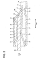
- FIG. 2 is a sectional view of an essential part showing a state where a tab is inserted in a main portion
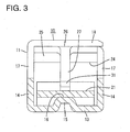
- FIG. 3 is a sectional view along A-A of FIG. 1 .
- a female terminal fitting 10 is integrally or unitarily formed by applying bending, folding and/or embossing and other processings to one electrically conductive (preferably metal) plate and includes a main portion 11, an unillustrated wire connection portion (preferably comprising a barrel portion) arranged behind the main portion 11 and a coupling portion 12 arranged between the wire connection portion (barrel portion) and the main portion 11.
- the wire connection portion (preferably the barrel portion is crimped and) connected to an end of an unillustrated wire and shares a base plate portion 13 substantially extending in forward and backward directions FBD with the main portion 11 and the coupling portion 12.
- the coupling portion 12 includes the base plate portion 13 and one or more, preferably a pair of coupling side plate portions 14 standing up or projecting from (preferably the opposite lateral edges of) the base plate portion 13.
- the base plate portion 13 of the coupling portion 12 preferably is deformed (preferably hammered from outside or below) to project inward or upward, thereby forming a raised portion 15.
- the raised portion 15 substantially is in the form of a pedestal and the upper or inner surface thereof is a substantially horizontal flat surface 16.
- the main portion 11 is in the form of a (preferably substantially rectangular or polygonal) tube and includes the base plate portion 13, one or more, preferably a pair of side plate portions 17 standing up or projecting from (preferably the substantially opposite lateral edges of) the base plate portion 13 and a facing plate portion 18 bent at the upper end of one side plate portion 17 preferably to substantially extend toward the upper end of the other side plate portion 17 as shown in FIG. 3 .
- the facing plate portion 18 preferably is arranged substantially parallel to the base plate portion 13.
- a front opening of the main portion 11 serves as a tab insertion opening 19, through which a tab 60 of a mating side is inserted in an inserting direction ID preferably substantially from front.
- One or more lower portions (preferably substantially lower halves) of the rear end(s) of the (preferably both) side plate portion(s) 17 are integrally or unitarily connected to the both coupling side plate portions 14.
- a (preferably substantially strip-shaped) first resilient piece 21 substantially extending in forward and backward directions FBD is formed in the main portion 11 particularly substantially in a cantiiever-shape.
- the first resilient piece 21 is formed to be resiliently deformable in a direction intersecting the inserting direction ID (preferably substantially upward and downward) with the front end (opening end) of the base plate portion 13 as a supporting point particularly by folding a tongue piece substantially extending forward from the front end of the base plate portion 13 substantially backward in such a manner as to have a substantially mountain shape.
- a contact portion 22, which can be brought into contact with the tab 60, is formed at or near a tip or laterally distal end of the mountain-shaped first resilient piece 21.
- One or more slits 23 are formed between (preferably the opposite sides of) a base end portion of the first resilient piece 21 (front end portion of the base plate portion 13) and the (preferably both) side plate portion(s) 17, whereby the base end portion of the first resilient piece 21 is retracted slightly backward from the front end of the main portion 11.
- a rear end portion (extending end portion) of the first resilient piece 21 is supported on and/or in contact with the flat surface 16 of the raised portion 15 from above.
- a (preferably substantially strip-shaped) second resilient piece 24 substantially extending in forward and backward directions FBD is also formed at a position substantially facing the first resilient piece 21.
- the second resilient piece 24, particularly shaped to substantially have a cantilever-shape includes an extending piece 25 substantially extending backward from the front end of the facing plate portion 18, a supporting point portion 26 located at the rear end (extending end) of the extending piece 25 and held in contact with the inner surface of the facing plate portion 18, and a pressing piece 27 substantially extending obliquely downward or inward to the back from the supporting point portion 26 toward the first resilient piece 21.
- the extending piece 25 and the supporting point portion 26 preferably are in the form of wide strips similar to the first resilient piece 21.
- the pressing piece 27 preferably is in the form of a narrow strip extending from a widthwise intermediate (preferably central) part of the rear end of the extending piece 25 (see FIG. 3 ).
- a front end portion of the extending piece 25 substantially is placed in close contact with the inner surface of the facing plate portion 18, and a part of the extending piece 25 except its front end portion is spaced apart from the inner surface of the facing plate portion 18.
- an intermediate part substantially facing (or substantially opposite to) the contact portion 22 of the first resilient piece 21 is formed into a substantially straight portion 28 extending in forward and backward directions FBD (and/or substantially parallel to the inserting direction ID) and/or arranged substantially in parallel with the inner surface of the facing plate portion 18.
- the supporting point portion 26 is formed at a bent portion or a tip of a mountain-shaped part where a rear end portion of the extending piece 25 extending obliquely upward or outward to the back and a front end portion of the pressing piece 27 extending obliquely downward or inward to the back meet. This supporting point portion 26 is constantly in contact with the inner surface of the facing plate portion 18.
- a bent-up portion 31 is formed by bending a leading or distal end portion of the pressing piece 27 to extend obliquely upward or outward to the back.
- a bent part of the bent-up portion 31 of the pressing piece 27 preferably is placed or pressed into contact with the rear end portion of the first resilient piece 21 from above and can resiliently and tightly hold the rear end portion of the first resilient piece 21 together with the raised portion 15.
- the first resilient piece 21 pressed by the pressing piece 27 is resiliently deformed with the front end of the base plate portion 13 as a supporting point and held in a pre-loaded state by maintaining this resiliently deformed state.
- Such a pressing piece 27 includes a touching portion 34 located at a position substantially facing an insertion path 35 for the tab 60 formed between the extending piece 25 and the first resilient piece 21, and a leading end portion of the tab 60 at least partly inserted up to a proper depth into the main portion 11 comes into contact with this touching portion 34.
- the pressing piece 27 held in contact with the tab 60 is pushed and inclined backward while the rear end portion thereof is moved onto the leading end portion of the tab 60, thereby at least partly releasing a state of pressing the first resilient piece 21.
- the pressing piece 27 is displaceable between a pressing position PP (see FIG. 1 ) where it gives a pressing force to the first resilient piece 21 and a retracted position RP (see FIG.
- a distance between the straight portion 28 of the extending piece 25 and the contact portion 22 of the first resilient piece 21 in a height direction is slightly smaller than the thickness of the tab 60.
- the female terminal fitting 10 according to this embodiment is constructed as described above. Next, functions thereof are described.
- the tab 60 is inserted into the main portion 11 of the female terminal fitting 10 in the inserting direction ID, preferably substantially from front. At this time, the tab 60 is inserted along forward and backward directions FBD through the tab insertion opening 19 and a depth of insertion increases while the tab 60 is substantially held in sliding contact with the extending piece 25 and the first resilient piece 21.
- the pressing piece 27 is at the pressing position PP and the first resilient piece 21 is kept in the pre-loaded state when the leading end portion of the tab 60 passes the insertion path 35, the tab 60 is not subjected to a large spring force from the first resilient piece 21 and there is no likelihood of particularly increasing frictional resistance between the tab 60 and the first resilient piece 21, the extending piece 25.
- the leading end portion of the tab 60 interferes with the touching portion 34 and the pressing piece 27 is pushed and inclined backward and moved towards or to the retracted position RP.
- the pre-loaded state of the first resilient piece 21 is released, the first resilient piece 21 is resiliently displaced upward or inward (toward the extending piece 25) with the front end of the base plate portion 13 as a supporting point, and a spring force is given to the tab 60 from below from the first resilient piece 21.
- the extending piece 25 substantially is displaced downward or inward (toward the first resilient piece 21) with the supporting point portion 26 as a supporting point and the straight portion 28 of the extending piece 25 comes to be held in contact with the upper surface of the tab 60 in forward and backward directions FBD.
- a leverage action with the touching portion 34 as an effort, the supporting point portion 26 as a fulcrum and the straight portion 28 as a load a force is exerted from the pressing piece 27 to press the tab 60 downward.
- the tab 60 properly inserted into the main portion 11 in this way is held in close and resilient contact with the extending piece 25 at its upper side and held in close and resilient contact with the first resilient piece 21 at its lower side, with the result that the tab 60 is held with an appropriate contact pressure from substantially opposite sides between the extending piece 25 and the first resilient piece 21.
- the first resilient piece 21 is kept in the pre-loaded state while the tab 60 is being inserted.
- the tab 60 is not subjected to a large spring force from the first resilient piece 21 and no large frictional resistance is produced between the first resilient piece 21 and the extending piece 25. Therefore, operability at the time of inserting the tab 60 is improved.
- the pre-loaded state of the first resilient piece 21 is released by the leading end portion of the tab 60 pushing and inclining the pressing piece 27, and the extending piece 25 is resiliently deformed toward the first resilient piece 21 with the supporting point portion 26 as a supporting point as the pressing piece 27 is inclined, whereby the tab 60 is resiliently and tightly held between the extending piece 25 and the first resilient piece 21. Therefore, a sufficient contact pressure can be ensured between the first resilient piece 21, the extending piece 25 and the tab 60.
- the pressing piece 27 presses the rear end portion (extend end portion) of the first resilient piece 21 distant from the supporting point position, it needs not exert a particularly large force and the first resilient piece 21 released from the pre-loaded state can smoothly return towards or to its original shape.
- the rear end portion of the first resilient piece 21 is tightly held between the pressing piece 27 and the flat surface 16 of the raised portion 15 of the base plate portion 13 in the pre-loaded state, loose movements of the first resilient piece 21 in the pre-loaded state are restricted.
- the spring force of the first resilient piece 21 and the length of the pressing piece 27 are set at appropriate values.
- a layer such as an oxide layer formed on the surface of the first resilient piece 21, the extending piece 25 or the tab 60 can be effectively removed by wiping or scratching.
- a first resilient piece 21 and a second resilient piece 24 are formed substantially opposite to (or substantially facing) each other in the main portion 11.
- the second resilient piece 24 includes an extending piece 25 substantially extending in an inserting direction ID of a tab 60, a supporting point portion 26 held in contact with the inner surface of a ceiling wall of a leading end portion of the extending piece 25 and a pressing piece 27 extending from the supporting point portion 26 toward the first resilient piece 21 and holding the first resilient piece 21 in a pre-loaded state by a leading end portion thereof pressing the first resilient piece 21.
- the pre-loaded state of the first resilient piece 21 is released by the tab 60 being at least partly inserted between the extending piece 25 and the first resilient piece 21 and a leading end portion of the tab 60 pushing and inclining the pressing piece 27, and the extending piece 25 is resiliently deformed with the supporting point portion 26 as a supporting point as the pressing piece 27 is inclined, whereby the tab 60 is resiliently held between the extending piece 25 and the first resilient piece 21.
Landscapes
- Engineering & Computer Science (AREA)
- Manufacturing & Machinery (AREA)
- Details Of Connecting Devices For Male And Female Coupling (AREA)
- Coupling Device And Connection With Printed Circuit (AREA)
- Manufacturing Of Electrical Connectors (AREA)
Abstract
An object of the present invention is to ensure a sufficient contact pressure to a tab while improving operability at the time of connecting the tab.
A first resilient piece 21 and a second resilient piece 24 are formed opposite to each other in the main portion 11. The second resilient piece 24 includes an extending piece 25 extending in an inserting direction of a tab 60, a supporting point portion 26 held in contact with the inner surface of a ceiling wall of a leading end portion of the extending piece 25 and a pressing piece 27 extending from the supporting point portion 26 toward the first resilient piece 21 and holding the first resilient piece 21 in a pre-loaded state by a leading end portion thereof pressing the first resilient piece 21. The pre-loaded state of the first resilient piece 21 is released by the tab 60 being inserted between the extending piece 25 and the first resilient piece 21 and a leading end portion of the tab 60 pushing and inclining the pressing piece 27, and the extending piece 25 is resiliently deformed with the supporting point portion 26 as a supporting point as the pressing piece 27 is inclined, whereby the tab 60 is resiliently held between the extending piece 25 and the first resilient piece 21.
Description
- The present invention relates to a female terminal fitting and to a method of connecting or assembling it with a corresponding tab.
- Japanese Unexamined Patent Publication No.
2008-282551 - In the case of the above conventional female terminal fitting, the tab is strongly pressed against the receiving portion by a spring force from the resilient contact piece in the process of being inserted into the main portion. Thus, as the spring force of the resilient contact piece increases, large frictional resistance is produced between the receiving portion and the tab, thereby causing a problem of deteriorating operability. In contrast, if the spring force of the resilient contact piece decreases, a sufficient contact pressure to the tab cannot be ensured although operability is improved.
- The present invention was developed in view of the above situation and an object thereof is to ensure a sufficient contact pressure to a tab while improving operability at the time of inserting the tab.
- This object is solved according to the invention by the features of the independent claims. Preferred embodiments of the invention are subject of the dependent claims.
- According to the invention, there is provided a female terminal fitting, comprising: a main portion for at least partly receiving a tab of a mating side, a first resilient piece resiliently deformably formed in or at the main portion, and a second resilient piece resiliently deformably formed in or at the main portion at a position substantially facing the first resilient piece in a deforming direction thereof, wherein the second resilient piece includes an extending piece substantially extending in an inserting direction of the tab from an opening end portion of one wall of the main portion, a supporting point portion held in contact with the inner surface of the one wall at an extending end portion of the extending piece and a pressing piece extending from the supporting point portion toward the first resilient piece and holding the first resilient piece in a pre-loaded state by an extending end portion thereof pressing the first resilient piece.
- According to a preferred embodiment of the invention, the pre-loaded state of the first resilient piece is released by the tab being inserted between the extending piece and the first resilient piece and/or a leading end portion of the tab pushing and inclining the pressing piece and the extending piece is resiliently deformed toward the first resilient piece with the supporting point portion as a supporting point as the pressing piece is pushed and inclined, whereby the tab is resiliently held between the extending piece and the first resilient piece.
- According to a preferred embodiment of the invention, there is provided a female terminal fitting, comprising: a tubular main portion for receiving a tab of a mating side, a first resilient piece resiliently deformably formed in the main portion, and a second resilient piece resiliently deformably formed in the main portion at a position facing the first resilient piece in a deforming direction thereof, wherein: the second resilient piece includes an extending piece extending in an inserting direction of the tab from an opening end portion of one wall of the main portion, a supporting point portion held in contact with the inner surface of the one wall at an extending end portion of the extending piece and a pressing piece extending from the supporting point portion toward the first resilient piece and holding the first resilient piece in a pre-loaded state by an extending end portion thereof pressing the first resilient piece, and the pre-loaded state of the first resilient piece is released by the tab being inserted between the extending piece and the first resilient piece and a leading end portion of the tab pushing and inclining the pressing piece and the extending piece is resiliently deformed toward the first resilient piece with the supporting point portion as a supporting point as the pressing piece is pushed and inclined, whereby the tab is resiliently held between the extending piece and the first resilient piece.
- When the tab is inserted into the main portion, the first resilient piece is kept in the pre-loaded state during the insertion of the tab until the pressing piece is pushed and inclined. Thus, the tab is not subjected to a large spring force from the first resilient piece and no large frictional resistance is produced between the first resilient piece and the extending piece. Therefore, operability at the time of inserting the tab is improved.
- The pre-loaded state of the first resilient piece is released by the leading end portion of the tab pushing and inclining the pressing piece and the extending piece is resiliently deformed toward the first resilient piece with the supporting point portion as a supporting point as the pressing piece is inclined, whereby the tab is resiliently and tightly held between the extending piece and the first resilient piece. Therefore, a sufficient contact pressure can be ensured between the first resilient piece, the extending piece and the tab.
- Preferably, the first resilient piece substantially extends in the inserting direction of the tab from an opening end portion of another wall of the main portion substantially facing the one wall.
- Further preferably, the pressing piece presses an extending end portion of the first resilient piece.
- Still further preferably, the first resilient piece extends in the inserting direction of the tab from an opening end portion of another wall of the main portion facing the one wall, and
the pressing piece presses an extending end portion of the first resilient piece. - Since the pressing piece presses the extending end portion of the first resilient piece, it needs not exert a particularly large force and the first resilient piece released from the pre-loaded state can smoothly return to its original shape.
- Most preferably, the extending end portion of the first resilient piece is tightly held between the pressing piece and the inner surface of the other wall in the pre-loaded state.
- Since the extending end portion of the first resilient piece is tightly held between the pressing piece and the inner surface of the other wall in the pre-loaded state, loose movements of the first resilient piece in the pre-loaded state are restricted.
- According to a preferred embodiment, an opening dimension of an insertion path for the tab formed between the extending piece and the first resilient piece when the first resilient piece is in the pre-loaded state is set to be smaller than the thickness of the tab.
- Since the tab can come into sliding contact with the first resilient piece and the extending piece during the insertion of the tab into the insertion path, a layer such as an oxide layer formed on the surface of the first resilient piece, the extending piece or the tab can be removed by wiping.
- According to a further preferred embodiment,, an opening dimension of an insertion path for the tab formed between the extending piece and the first resilient piece when the first resilient piece is in the pre-loaded state is set to be larger than the thickness of the tab.
- Since substantially no frictional resistance is produced between the first resilient piece, the extending piece and the tab, a work load at the time of inserting the tab into the insertion path is more mitigated.
- According to the invention, there is further provided a method of connecting a female terminal fitting, in particular according to the invention or a preferred embodiment thereof, with a tab, comprising the following steps:
- providing a female terminal fitting having a first resilient piece resiliently deformably formed in or at a main portion for at least partly receiving the tab, and a second resilient piece resiliently deformably formed in or at the main portion at a position substantially facing the first resilient piece in a deforming direction thereof, and
- at least partly inserting the tab in an inserting direction into the main portion whereby the tab is resiliently held between an extending piece of the second resilient piece, which substantially extends in the inserting direction of the tab from an opening end portion of one wall of the main portion, and the first resilient piece, while
- holding a supporting point portion of the second resilient piece in contact with the inner surface of the one wall at an extending end portion of the extending piece and
- holding the first resilient piece in a pre-loaded state by an extending end portion of a pressing piece, which extends from the supporting point portion toward the first resilient piece, pressing the first resilient piece.
- According to a preferred embodiment of the invention, the pre-loaded state of the first resilient piece is released by the tab being inserted between the extending piece and the first resilient piece and/or a leading end portion of the tab pushing and inclining the pressing piece and the extending piece is resiliently deformed toward the first resilient piece with the supporting point portion as a supporting point as the pressing piece is pushed and inclined, whereby the tab is resiliently held between the extending piece and the first resilient piece.
- Preferably, the first resilient piece is arranged to substantially extend in the inserting direction of the tab from an opening end portion of another wall of the main portion substantially facing the one wall.
- Further preferably, the pressing piece presses an extending end portion of the first resilient piece.
- Still further preferably, the extending end portion of the first resilient piece is tightly held between the pressing piece and the inner surface of the other wall in the pre-loaded state.
- According to a preferred embodiment of the invention, an opening dimension of an insertion path for the tab formed between the extending piece and the first resilient piece when the first resilient piece is in the pre-loaded state is set to be smaller than the thickness of the tab.
- According to a further preferred embodiment of the invention, an opening dimension of an insertion path for the tab formed between the extending piece and the first resilient piece when the first resilient piece is in the pre-loaded state is set to be larger than the thickness of the tab.
- These and other objects, features and advantages of the present invention will become more apparent upon reading of the following detailed description of preferred embodiments and accompanying drawings. It should be understood that even though embodiments are separately described, single features thereof may be combined to additional embodiments.
-
FIG. 1 is a sectional view of an essential part of a female terminal fitting according to one embodiment of the invention, -
FIG. 2 is a sectional view of an essential part showing a state where a tab is inserted in a main portion, and -
FIG. 3 is a sectional view along A-A ofFIG. 1 . - One embodiment of the present invention is described with reference to
FIGS. 1 to 3 . A female terminal fitting 10 according to this embodiment is integrally or unitarily formed by applying bending, folding and/or embossing and other processings to one electrically conductive (preferably metal) plate and includes amain portion 11, an unillustrated wire connection portion (preferably comprising a barrel portion) arranged behind themain portion 11 and acoupling portion 12 arranged between the wire connection portion (barrel portion) and themain portion 11. - The wire connection portion (preferably the barrel portion is crimped and) connected to an end of an unillustrated wire and shares a
base plate portion 13 substantially extending in forward and backward directions FBD with themain portion 11 and thecoupling portion 12. Thecoupling portion 12 includes thebase plate portion 13 and one or more, preferably a pair of couplingside plate portions 14 standing up or projecting from (preferably the opposite lateral edges of) thebase plate portion 13. Thebase plate portion 13 of thecoupling portion 12 preferably is deformed (preferably hammered from outside or below) to project inward or upward, thereby forming a raisedportion 15. The raisedportion 15 substantially is in the form of a pedestal and the upper or inner surface thereof is a substantially horizontalflat surface 16. - The
main portion 11 is in the form of a (preferably substantially rectangular or polygonal) tube and includes thebase plate portion 13, one or more, preferably a pair ofside plate portions 17 standing up or projecting from (preferably the substantially opposite lateral edges of) thebase plate portion 13 and a facingplate portion 18 bent at the upper end of oneside plate portion 17 preferably to substantially extend toward the upper end of the otherside plate portion 17 as shown inFIG. 3 . The facingplate portion 18 preferably is arranged substantially parallel to thebase plate portion 13. A front opening of themain portion 11 serves as a tab insertion opening 19, through which atab 60 of a mating side is inserted in an inserting direction ID preferably substantially from front. One or more lower portions (preferably substantially lower halves) of the rear end(s) of the (preferably both) side plate portion(s) 17 are integrally or unitarily connected to the both couplingside plate portions 14. - A (preferably substantially strip-shaped) first
resilient piece 21 substantially extending in forward and backward directions FBD is formed in themain portion 11 particularly substantially in a cantiiever-shape. The firstresilient piece 21 is formed to be resiliently deformable in a direction intersecting the inserting direction ID (preferably substantially upward and downward) with the front end (opening end) of thebase plate portion 13 as a supporting point particularly by folding a tongue piece substantially extending forward from the front end of thebase plate portion 13 substantially backward in such a manner as to have a substantially mountain shape. Acontact portion 22, which can be brought into contact with thetab 60, is formed at or near a tip or laterally distal end of the mountain-shaped firstresilient piece 21. One ormore slits 23 are formed between (preferably the opposite sides of) a base end portion of the first resilient piece 21 (front end portion of the base plate portion 13) and the (preferably both) side plate portion(s) 17, whereby the base end portion of the firstresilient piece 21 is retracted slightly backward from the front end of themain portion 11. A rear end portion (extending end portion) of the firstresilient piece 21 is supported on and/or in contact with theflat surface 16 of the raisedportion 15 from above. - In the
main portion 11, a (preferably substantially strip-shaped) secondresilient piece 24 substantially extending in forward and backward directions FBD is also formed at a position substantially facing the firstresilient piece 21. - The second
resilient piece 24, particularly shaped to substantially have a cantilever-shape, includes an extendingpiece 25 substantially extending backward from the front end of the facingplate portion 18, a supportingpoint portion 26 located at the rear end (extending end) of the extendingpiece 25 and held in contact with the inner surface of the facingplate portion 18, and apressing piece 27 substantially extending obliquely downward or inward to the back from the supportingpoint portion 26 toward the firstresilient piece 21. The extendingpiece 25 and the supportingpoint portion 26 preferably are in the form of wide strips similar to the firstresilient piece 21. On the other hand, thepressing piece 27 preferably is in the form of a narrow strip extending from a widthwise intermediate (preferably central) part of the rear end of the extending piece 25 (seeFIG. 3 ). - A front end portion of the extending
piece 25 substantially is placed in close contact with the inner surface of the facingplate portion 18, and a part of the extendingpiece 25 except its front end portion is spaced apart from the inner surface of the facingplate portion 18. Out of this part of the extendingpiece 25, an intermediate part substantially facing (or substantially opposite to) thecontact portion 22 of the firstresilient piece 21 is formed into a substantiallystraight portion 28 extending in forward and backward directions FBD (and/or substantially parallel to the inserting direction ID) and/or arranged substantially in parallel with the inner surface of the facingplate portion 18. - The supporting
point portion 26 is formed at a bent portion or a tip of a mountain-shaped part where a rear end portion of the extendingpiece 25 extending obliquely upward or outward to the back and a front end portion of thepressing piece 27 extending obliquely downward or inward to the back meet. This supportingpoint portion 26 is constantly in contact with the inner surface of the facingplate portion 18. - A bent-up
portion 31 is formed by bending a leading or distal end portion of thepressing piece 27 to extend obliquely upward or outward to the back. A bent part of the bent-upportion 31 of thepressing piece 27 preferably is placed or pressed into contact with the rear end portion of the firstresilient piece 21 from above and can resiliently and tightly hold the rear end portion of the firstresilient piece 21 together with the raisedportion 15. The firstresilient piece 21 pressed by thepressing piece 27 is resiliently deformed with the front end of thebase plate portion 13 as a supporting point and held in a pre-loaded state by maintaining this resiliently deformed state. Such apressing piece 27 includes a touchingportion 34 located at a position substantially facing aninsertion path 35 for thetab 60 formed between the extendingpiece 25 and the firstresilient piece 21, and a leading end portion of thetab 60 at least partly inserted up to a proper depth into themain portion 11 comes into contact with this touchingportion 34. Thepressing piece 27 held in contact with thetab 60 is pushed and inclined backward while the rear end portion thereof is moved onto the leading end portion of thetab 60, thereby at least partly releasing a state of pressing the firstresilient piece 21. In other words, thepressing piece 27 is displaceable between a pressing position PP (seeFIG. 1 ) where it gives a pressing force to the firstresilient piece 21 and a retracted position RP (seeFIG. 2 ) where the state of pressing the firstresilient piece 21 is released. When thepressing piece 27 is at the pressing position PP, i.e. when the firstresilient piece 21 is in the pre-loaded state, a distance between thestraight portion 28 of the extendingpiece 25 and thecontact portion 22 of the firstresilient piece 21 in a height direction (opening dimension of the insertion path 35) is slightly smaller than the thickness of thetab 60. - The female terminal fitting 10 according to this embodiment is constructed as described above. Next, functions thereof are described.
- As an unillustrated connector accommodating the at least one female terminal fitting 10 is connected, the
tab 60 is inserted into themain portion 11 of the female terminal fitting 10 in the inserting direction ID, preferably substantially from front. At this time, thetab 60 is inserted along forward and backward directions FBD through thetab insertion opening 19 and a depth of insertion increases while thetab 60 is substantially held in sliding contact with the extendingpiece 25 and the firstresilient piece 21. Since thepressing piece 27 is at the pressing position PP and the firstresilient piece 21 is kept in the pre-loaded state when the leading end portion of thetab 60 passes theinsertion path 35, thetab 60 is not subjected to a large spring force from the firstresilient piece 21 and there is no likelihood of particularly increasing frictional resistance between thetab 60 and the firstresilient piece 21, the extendingpiece 25. - Thereafter, when the
tab 60 enters an insertion final stage immediately before being sufficiently or completely inserted, the leading end portion of thetab 60 interferes with the touchingportion 34 and thepressing piece 27 is pushed and inclined backward and moved towards or to the retracted position RP. Simultaneously with this, the pre-loaded state of the firstresilient piece 21 is released, the firstresilient piece 21 is resiliently displaced upward or inward (toward the extending piece 25) with the front end of thebase plate portion 13 as a supporting point, and a spring force is given to thetab 60 from below from the firstresilient piece 21. - As the
pressing piece 27 is moved to the retracted position RP, the extendingpiece 25 substantially is displaced downward or inward (toward the first resilient piece 21) with the supportingpoint portion 26 as a supporting point and thestraight portion 28 of the extendingpiece 25 comes to be held in contact with the upper surface of thetab 60 in forward and backward directions FBD. At this time, by a leverage action with the touchingportion 34 as an effort, the supportingpoint portion 26 as a fulcrum and thestraight portion 28 as a load, a force is exerted from thepressing piece 27 to press thetab 60 downward. - The
tab 60 properly inserted into themain portion 11 in this way is held in close and resilient contact with the extendingpiece 25 at its upper side and held in close and resilient contact with the firstresilient piece 21 at its lower side, with the result that thetab 60 is held with an appropriate contact pressure from substantially opposite sides between the extendingpiece 25 and the firstresilient piece 21. - As described above, according to this embodiment, the first
resilient piece 21 is kept in the pre-loaded state while thetab 60 is being inserted. Thus, thetab 60 is not subjected to a large spring force from the firstresilient piece 21 and no large frictional resistance is produced between the firstresilient piece 21 and the extendingpiece 25. Therefore, operability at the time of inserting thetab 60 is improved. - The pre-loaded state of the first
resilient piece 21 is released by the leading end portion of thetab 60 pushing and inclining thepressing piece 27, and the extendingpiece 25 is resiliently deformed toward the firstresilient piece 21 with the supportingpoint portion 26 as a supporting point as thepressing piece 27 is inclined, whereby thetab 60 is resiliently and tightly held between the extendingpiece 25 and the firstresilient piece 21. Therefore, a sufficient contact pressure can be ensured between the firstresilient piece 21, the extendingpiece 25 and thetab 60. - Further, since the
pressing piece 27 presses the rear end portion (extend end portion) of the firstresilient piece 21 distant from the supporting point position, it needs not exert a particularly large force and the firstresilient piece 21 released from the pre-loaded state can smoothly return towards or to its original shape. - Furthermore, since the rear end portion of the first
resilient piece 21 is tightly held between thepressing piece 27 and theflat surface 16 of the raisedportion 15 of thebase plate portion 13 in the pre-loaded state, loose movements of the firstresilient piece 21 in the pre-loaded state are restricted. In this case, by adjusting the height (raised amount) of the raisedportion 15, the spring force of the firstresilient piece 21 and the length of thepressing piece 27 are set at appropriate values. - Further, since the
tab 60 substantially comes into sliding contact with the firstresilient piece 21 and the extendingpiece 25 during the insertion of thetab 60 into theinsertion path 35, a layer such as an oxide layer formed on the surface of the firstresilient piece 21, the extendingpiece 25 or thetab 60 can be effectively removed by wiping or scratching. - Accordingly, to ensure a sufficient contact pressure to a tab while improving operability at the time of connecting the tab, a first
resilient piece 21 and a secondresilient piece 24 are formed substantially opposite to (or substantially facing) each other in themain portion 11. The secondresilient piece 24 includes an extendingpiece 25 substantially extending in an inserting direction ID of atab 60, a supportingpoint portion 26 held in contact with the inner surface of a ceiling wall of a leading end portion of the extendingpiece 25 and apressing piece 27 extending from the supportingpoint portion 26 toward the firstresilient piece 21 and holding the firstresilient piece 21 in a pre-loaded state by a leading end portion thereof pressing the firstresilient piece 21. The pre-loaded state of the firstresilient piece 21 is released by thetab 60 being at least partly inserted between the extendingpiece 25 and the firstresilient piece 21 and a leading end portion of thetab 60 pushing and inclining thepressing piece 27, and the extendingpiece 25 is resiliently deformed with the supportingpoint portion 26 as a supporting point as thepressing piece 27 is inclined, whereby thetab 60 is resiliently held between the extendingpiece 25 and the firstresilient piece 21. - The present invention is not limited to the above described and illustrated embodiment. For example, the following embodiments are also included in the technical scope of the present invention.
- (1) Contrary to the above embodiment, the opening dimension of the insertion path formed between the extending piece and the first resilient piece when the pressing piece is at the pressing position and the first resilient piece is in the pre-loaded state may be set to be larger than the thickness of the tab. By doing so, substantially no frictional resistance is produced between the first resilient piece, the extending piece and the tab, wherefore a work load at the time of inserting the tab into the insertion path can be more mitigated.
- (2) The first resilient piece may extend forward from the rear end portion of the main portion and may be resiliently deformable with the rear end portion as a supporting point.
- (3) The raised portion may be formed in the main portion or may be so formed as to extend from the main portion to the coupling portion.
- (4) The pressing piece may partly have the same width as the extending piece.
-
- 10 ... female terminal fitting
- 11 ... main portion
- 13 ... base plate portion (one wall)
- 18 ... facing plate portion (other wall)
- 21 ... first resilient piece
- 24 ... second resilient piece
- 25 ... extending piece
- 26 ... supporting point portion
- 27 ... pressing piece
- 35 ... insertion path
- 60 ... tab
Claims (15)
- A female terminal fitting, comprising:a main portion (11) for at least partly receiving a tab (60) of a mating side,a first resilient piece (21) resiliently deformably formed in or at the main portion (11), anda second resilient piece (24) resiliently deformably formed in or at the main portion (11) at a position substantially facing the first resilient piece (21) in a deforming direction thereof,wherein:the second resilient piece (24) includes an extending piece (25) substantially extending in an inserting direction (ID) of the tab (60) from an opening end portion of one wall (13) of the main portion (11), a supporting point portion (26) held in contact with the inner surface of the one wall (13) at an extending end portion of the extending piece (25) and a pressing piece (27) extending from the supporting point portion (26) toward the first resilient piece (21) and holding the first resilient piece (21) in a pre-loaded state by an extending end portion thereof pressing the first resilient piece (21).
- A female terminal fitting according to claim 1, wherein the pre-loaded state of the first resilient piece (21) is released by the tab (60) being inserted between the extending piece (25) and the first resilient piece (21) and/or a leading end portion of the tab (60) pushing and inclining the pressing piece (27) and the extending piece (25) is resiliently deformed toward the first resilient piece (21) with the supporting point portion (26) as a supporting point as the pressing piece (27) is pushed and inclined, whereby the tab (60) is resiliently held between the extending piece (25) and the first resilient piece (21).
- A female terminal fitting according to any one of the preceding claims, wherein the first resilient piece (21) substantially extends in the inserting direction (ID) of the tab (60) from an opening end portion of another wall (18) of the main portion (11) substantially facing the one wall (13).
- A female terminal fitting according to any one of the preceding claims, wherein the pressing piece (27) presses an extending end portion of the first resilient piece (21).
- A female terminal fitting according to claim 4, wherein the extending end portion of the first resilient piece (21) is tightly held between the pressing piece (27) and the inner surface of the other wall (18) in the pre-loaded state.
- A female terminal fitting according to any one of the preceding claims, wherein an opening dimension of an insertion path (35) for the tab (60) formed between the extending piece (25) and the first resilient piece (21) when the first resilient piece (21) is in the pre-loaded state is set to be smaller than the thickness of the tab (60).
- A female terminal fitting according to any one of the preceding claims 1 to 5, wherein an opening dimension of an insertion path (35) for the tab (60) formed between the extending piece (25) and the first resilient piece (21) when the first resilient piece (21) is in the pre-loaded state is set to be larger than the thickness of the tab (60).
- A female terminal fitting according to any one of the preceding claims, wherein the pressing piece (27) is displaceable between a pressing position (PP) where it gives a pressing force to the first resilient piece (21) and a retracted position (RP) where the state of pressing the first resilient piece (21) is released.
- A method of connecting a female terminal fitting (10) with a tab (60), comprising the following steps:providing a female terminal fitting (10) having a first resilient piece (21) resiliently deformably formed in or at a main portion (11) for at least partly receiving the tab (60), and a second resilient piece (24) resiliently deformably formed in or at the main portion (11) at a position substantially facing the first resilient piece (21) in a deforming direction thereof, andat least partly inserting the tab (60) in an inserting direction (ID) into the main portion (11) whereby the tab (60) is resiliently held between an extending piece (25) of the second resilient piece (24), which substantially extends in the inserting direction (ID) of the tab (60) from an opening end portion of one wall (13) of the main portion (11), and the first resilient piece (21), whileholding a supporting point portion (26) of the second resilient piece (24) in contact with the inner surface of the one wall (13) at an extending end portion of the extending piece (25) andholding the first resilient piece (21) in a pre-loaded state by an extending end portion of a pressing piece (27), which extends from the supporting point portion (26) toward the first resilient piece (21), pressing the first resilient piece (21).
- A method according to claim 9, wherein the pre-loaded state of the first resilient piece (21) is released by the tab (60) being inserted between the extending piece (25) and the first resilient piece (21) and/or a leading end portion of the tab (60) pushing and inclining the pressing piece (27) and the extending piece (25) is resiliently deformed toward the first resilient piece (21) with the supporting point portion (26) as a supporting point as the pressing piece (27) is pushed and inclined, whereby the tab (60) is resiliently held between the extending piece (25) and the first resilient piece (21).
- A method according to claim 9 or 10, wherein the first resilient piece (21) is arranged to substantially extend in the inserting direction (ID) of the tab (60) from an opening end portion of another wall (18) of the main portion (11) substantially facing the one wall (13).
- A method according to any one of the preceding claims 9 to 11, wherein the pressing piece (27) presses an extending end portion of the first resilient piece (21).
- A method according to claim 12, wherein the extending end portion of the first resilient piece (21) is tightly held between the pressing piece (27) and the inner surface of the other wall (18) in the pre-loaded state.
- A method according to any one of the preceding claims 9 to 13, wherein an opening dimension of an insertion path (35) for the tab (60) formed between the extending piece (25) and the first resilient piece (21) when the first resilient piece (21) is in the pre-loaded state is set to be smaller than the thickness of the tab (60).
- A method according to any one of the preceding claims 9 to 13, wherein an opening dimension of an insertion path (35) for the tab (60) formed between the extending piece (25) and the first resilient piece (21) when the first resilient piece (21) is in the pre-loaded state is set to be larger than the thickness of the tab (60).
Applications Claiming Priority (1)
| Application Number | Priority Date | Filing Date | Title |
|---|---|---|---|
| JP2009234873A JP5251819B2 (en) | 2009-10-09 | 2009-10-09 | Female terminal bracket |
Publications (1)
| Publication Number | Publication Date |
|---|---|
| EP2309603A1 true EP2309603A1 (en) | 2011-04-13 |
Family
ID=42953772
Family Applications (1)
| Application Number | Title | Priority Date | Filing Date |
|---|---|---|---|
| EP10009576A Withdrawn EP2309603A1 (en) | 2009-10-09 | 2010-09-14 | Female terminal fitting and method of connecting it |
Country Status (4)
| Country | Link |
|---|---|
| US (1) | US8241076B2 (en) |
| EP (1) | EP2309603A1 (en) |
| JP (1) | JP5251819B2 (en) |
| CN (1) | CN102044778A (en) |
Families Citing this family (25)
| Publication number | Priority date | Publication date | Assignee | Title |
|---|---|---|---|---|
| US8323061B2 (en) * | 2009-01-20 | 2012-12-04 | Molex Incorporated | Miniature receptacle terminals |
| JP5251819B2 (en) * | 2009-10-09 | 2013-07-31 | 住友電装株式会社 | Female terminal bracket |
| JP5682520B2 (en) * | 2011-09-14 | 2015-03-11 | 住友電装株式会社 | Terminal fitting |
| DE102012002145A1 (en) | 2012-02-04 | 2013-08-08 | Kostal Kontakt Systeme Gmbh | Sleeve contact for a zero-force electrical connector |
| US8974256B2 (en) * | 2012-04-26 | 2015-03-10 | Sumitomo Wiring Systems, Ltd. | Terminal fitting and production method therefor |
| CN202772303U (en) * | 2012-09-04 | 2013-03-06 | 泰科电子(上海)有限公司 | Electrical connector and electrical connector assembly |
| JP2014160545A (en) * | 2013-02-19 | 2014-09-04 | Sumitomo Wiring Syst Ltd | Female terminal metal fitting |
| JP2014170709A (en) * | 2013-03-05 | 2014-09-18 | Sumitomo Wiring Syst Ltd | Female terminal fitting |
| WO2014195749A1 (en) | 2013-06-07 | 2014-12-11 | FCI Asia Pte. Ltd. | Cable connector |
| US9972932B2 (en) * | 2013-08-19 | 2018-05-15 | Fci Americas Technology Llc | Electrical connector with high retention force |
| WO2015081986A1 (en) * | 2013-12-03 | 2015-06-11 | Fci Asia Pte.Ltd | Connector and pin receiving contact for such a connector |
| US9118130B1 (en) * | 2014-02-06 | 2015-08-25 | Delphi Technologies, Inc. | Low insertion force terminal |
| CN103811906B (en) * | 2014-02-10 | 2019-02-12 | 连展科技电子(昆山)有限公司 | The terminal of electric connector |
| JP6357334B2 (en) * | 2014-03-28 | 2018-07-11 | 矢崎総業株式会社 | Connection structure of crimp terminal and electric wire |
| JP6276113B2 (en) * | 2014-06-02 | 2018-02-07 | ホシデン株式会社 | connector |
| KR101630766B1 (en) | 2014-10-17 | 2016-06-15 | 몰렉스 엘엘씨 | Card socket for electronic device |
| US9917389B2 (en) * | 2015-09-14 | 2018-03-13 | Erich Jaeger Gmbh & Co. Kg | Flat terminal and socket for electrical plug-and-socket connection |
| JP6543284B2 (en) * | 2017-02-10 | 2019-07-10 | タイコエレクトロニクスジャパン合同会社 | Female contact and mating structure of contact |
| KR102447833B1 (en) * | 2018-02-09 | 2022-09-27 | 주성엔지니어링(주) | power interface |
| WO2019178520A1 (en) | 2018-03-16 | 2019-09-19 | Fci Usa Llc | High density electrical connectors |
| CN113363748B (en) * | 2020-03-05 | 2023-12-08 | 泰科电子(上海)有限公司 | Terminal connectors and socket terminals |
| JP7435362B2 (en) * | 2020-08-25 | 2024-02-21 | 住友電装株式会社 | Terminal fittings and chain terminals |
| JP7609592B2 (en) * | 2020-09-28 | 2025-01-07 | 矢崎総業株式会社 | Terminals, wire harnesses, and wires with terminals |
| JP7620446B2 (en) * | 2021-02-19 | 2025-01-23 | 矢崎総業株式会社 | Connection structure between female and male terminals |
| CN115120499B (en) * | 2022-06-27 | 2025-02-11 | 安翰科技(武汉)股份有限公司 | Drug release capsules |
Citations (3)
| Publication number | Priority date | Publication date | Assignee | Title |
|---|---|---|---|---|
| EP1091449A2 (en) * | 1999-10-08 | 2001-04-11 | Sumitomo Wiring Systems, Ltd. | Female terminal fitting |
| US20070218763A1 (en) * | 2006-02-28 | 2007-09-20 | Peter Rehbein | Electric plug-in connector having a prestressed contact lamina |
| EP1990866A1 (en) * | 2007-05-08 | 2008-11-12 | Sumitomo Wiring Systems, Ltd. | A female terminal fitting |
Family Cites Families (28)
| Publication number | Priority date | Publication date | Assignee | Title |
|---|---|---|---|---|
| JPS61237375A (en) * | 1985-04-11 | 1986-10-22 | アンプ インコ−ポレ−テツド | Receptacle terminal |
| JPH0469863U (en) * | 1990-10-30 | 1992-06-19 | ||
| JP2686199B2 (en) * | 1992-01-28 | 1997-12-08 | 矢崎総業株式会社 | Female terminal fitting |
| US5593328A (en) * | 1993-11-04 | 1997-01-14 | Sumitomo Wiring Systems, Ltd. | Female terminal fitting for connector |
| IT1273127B (en) * | 1994-04-12 | 1997-07-04 | Framatome Connectors Italia | ELECTRIC CONNECTOR |
| JP3533536B2 (en) * | 1994-07-11 | 2004-05-31 | 住友電装株式会社 | Female terminal fitting |
| JP3093954B2 (en) * | 1995-05-26 | 2000-10-03 | 矢崎総業株式会社 | Female terminal fitting |
| JP3258534B2 (en) * | 1995-07-28 | 2002-02-18 | タイコエレクトロニクスアンプ株式会社 | Female contact |
| JP3315313B2 (en) * | 1996-05-17 | 2002-08-19 | 矢崎総業株式会社 | Connector structure |
| US6062918A (en) * | 1996-07-01 | 2000-05-16 | The Whitaker Corporation | Electrical receptacle contact assembly |
| US6024612A (en) * | 1997-09-23 | 2000-02-15 | The Whitaker Corporation | Receptacle contact |
| JPH11214058A (en) * | 1998-01-29 | 1999-08-06 | Yazaki Corp | Female terminal |
| JP2000208216A (en) * | 1999-01-11 | 2000-07-28 | Yazaki Corp | Low insertion force connector |
| JP3620786B2 (en) * | 2000-01-24 | 2005-02-16 | 矢崎総業株式会社 | Terminal bracket |
| US6293833B1 (en) * | 2001-01-05 | 2001-09-25 | Yazaki North America | Low insertion force, high contact force terminal spring |
| US6264509B1 (en) * | 2001-01-10 | 2001-07-24 | Yazaki North America, Inc. | High cycle terminal with protected failsafe contact |
| JP3875526B2 (en) * | 2001-08-10 | 2007-01-31 | 矢崎総業株式会社 | Terminal spring structure |
| JP3767506B2 (en) * | 2002-04-03 | 2006-04-19 | 住友電装株式会社 | Female terminal fitting |
| DE60312848T2 (en) * | 2002-05-17 | 2007-09-06 | Mitsubishi Cable Industries, Ltd. | CONNECTION CONNECTION |
| JP2005129389A (en) * | 2003-10-24 | 2005-05-19 | Yazaki Corp | Relay terminal |
| JP2005228555A (en) * | 2004-02-12 | 2005-08-25 | Yazaki Corp | Female terminal |
| JP4483601B2 (en) * | 2005-01-28 | 2010-06-16 | 住友電装株式会社 | Female terminal bracket |
| DE102006009075A1 (en) * | 2006-02-28 | 2007-08-30 | Robert Bosch Gmbh | Electrical connector has compound spring is arranged between contact disk and external wall of contact body, where plugging retainer having contact pin and contact disk which laterally limits plugging retainer |
| JP4749919B2 (en) * | 2006-04-12 | 2011-08-17 | 日本圧着端子製造株式会社 | Spring loaded female terminal |
| US7371133B1 (en) * | 2007-01-18 | 2008-05-13 | Delphi Technologies, Inc. | Electrical socket terminal having a contact stabilizer |
| DE102008017043B3 (en) * | 2008-04-03 | 2009-09-03 | Lear Corp., Southfield | Electrical bushing contact producing method for receiving plug contact for electrical connection in motor vehicle environment, involves folding contact arm such that arm forms elastic spring, which contacts plug contact |
| JP5251819B2 (en) * | 2009-10-09 | 2013-07-31 | 住友電装株式会社 | Female terminal bracket |
| JP5482556B2 (en) * | 2010-08-06 | 2014-05-07 | 住友電装株式会社 | Terminal fitting |
-
2009
- 2009-10-09 JP JP2009234873A patent/JP5251819B2/en not_active Expired - Fee Related
-
2010
- 2010-09-14 EP EP10009576A patent/EP2309603A1/en not_active Withdrawn
- 2010-09-29 CN CN2010105057525A patent/CN102044778A/en active Pending
- 2010-10-04 US US12/896,934 patent/US8241076B2/en not_active Expired - Fee Related
Patent Citations (4)
| Publication number | Priority date | Publication date | Assignee | Title |
|---|---|---|---|---|
| EP1091449A2 (en) * | 1999-10-08 | 2001-04-11 | Sumitomo Wiring Systems, Ltd. | Female terminal fitting |
| US20070218763A1 (en) * | 2006-02-28 | 2007-09-20 | Peter Rehbein | Electric plug-in connector having a prestressed contact lamina |
| EP1990866A1 (en) * | 2007-05-08 | 2008-11-12 | Sumitomo Wiring Systems, Ltd. | A female terminal fitting |
| JP2008282551A (en) | 2007-05-08 | 2008-11-20 | Sumitomo Wiring Syst Ltd | Female terminal fitting |
Also Published As
| Publication number | Publication date |
|---|---|
| US20110086557A1 (en) | 2011-04-14 |
| JP5251819B2 (en) | 2013-07-31 |
| JP2011082082A (en) | 2011-04-21 |
| CN102044778A (en) | 2011-05-04 |
| US8241076B2 (en) | 2012-08-14 |
Similar Documents
| Publication | Publication Date | Title |
|---|---|---|
| US8241076B2 (en) | Female terminal fitting | |
| US7513806B2 (en) | Female terminal fitting | |
| EP2852004B1 (en) | Terminal fitting | |
| US8795007B2 (en) | Terminal fitting | |
| US8998656B2 (en) | Terminal fitting having auxiliary spring with support | |
| US9236675B2 (en) | Terminal fitting | |
| EP2375512B1 (en) | Terminal fitting and production method therefor | |
| EP2244334A1 (en) | Terminal fitting and method of forming it | |
| EP1801922A2 (en) | A terminal fitting | |
| US8523619B2 (en) | Terminal fitting | |
| WO2003098746A1 (en) | Connection terminal | |
| JP6026562B2 (en) | Sleeve contact for electrical connector with ZIF structure | |
| US7168981B2 (en) | Connector | |
| CN107086396A (en) | Female terminal and manufacturing method of female terminal | |
| JP2009176617A (en) | Terminals, and terminal connecting structure | |
| US20110294366A1 (en) | Terminal fitting | |
| US11888277B2 (en) | Terminal and electric cable including terminal | |
| JP2010010152A (en) | Connector assembly having cable connector and substrate connector | |
| US20220224024A1 (en) | Terminal and wire with terminal | |
| US20030190847A1 (en) | Female terminal fitting | |
| US6824433B2 (en) | Terminal fitting | |
| US10367289B2 (en) | Terminal connecting structure and connector device | |
| JP2004362832A (en) | Terminal fitting | |
| EP1811608B1 (en) | A terminal fitting and connector provided therewith | |
| JP4661664B2 (en) | Female terminal bracket |
Legal Events
| Date | Code | Title | Description |
|---|---|---|---|
| PUAI | Public reference made under article 153(3) epc to a published international application that has entered the european phase |
Free format text: ORIGINAL CODE: 0009012 |
|
| AK | Designated contracting states |
Kind code of ref document: A1 Designated state(s): AL AT BE BG CH CY CZ DE DK EE ES FI FR GB GR HR HU IE IS IT LI LT LU LV MC MK MT NL NO PL PT RO SE SI SK SM TR |
|
| AX | Request for extension of the european patent |
Extension state: BA ME RS |
|
| 17P | Request for examination filed |
Effective date: 20110915 |
|
| GRAP | Despatch of communication of intention to grant a patent |
Free format text: ORIGINAL CODE: EPIDOSNIGR1 |
|
| STAA | Information on the status of an ep patent application or granted ep patent |
Free format text: STATUS: THE APPLICATION IS DEEMED TO BE WITHDRAWN |
|
| 18D | Application deemed to be withdrawn |
Effective date: 20130514 |