US20030190847A1 - Female terminal fitting - Google Patents
Female terminal fitting Download PDFInfo
- Publication number
- US20030190847A1 US20030190847A1 US10/405,260 US40526003A US2003190847A1 US 20030190847 A1 US20030190847 A1 US 20030190847A1 US 40526003 A US40526003 A US 40526003A US 2003190847 A1 US2003190847 A1 US 2003190847A1
- Authority
- US
- United States
- Prior art keywords
- contact piece
- terminal fitting
- resilient contact
- female terminal
- fold
- Prior art date
- Legal status (The legal status is an assumption and is not a legal conclusion. Google has not performed a legal analysis and makes no representation as to the accuracy of the status listed.)
- Granted
Links
- 230000013011 mating Effects 0.000 claims description 9
- 238000005520 cutting process Methods 0.000 claims description 7
- 238000002788 crimping Methods 0.000 description 4
- 238000003780 insertion Methods 0.000 description 3
- 230000037431 insertion Effects 0.000 description 3
- 230000007423 decrease Effects 0.000 description 2
- 238000000034 method Methods 0.000 description 2
- 238000005452 bending Methods 0.000 description 1
- 238000006243 chemical reaction Methods 0.000 description 1
- 238000006073 displacement reaction Methods 0.000 description 1
- 238000004049 embossing Methods 0.000 description 1
- 238000005242 forging Methods 0.000 description 1
- 238000010438 heat treatment Methods 0.000 description 1
- 238000009413 insulation Methods 0.000 description 1
- 238000003825 pressing Methods 0.000 description 1
- 238000005476 soldering Methods 0.000 description 1
- 238000005496 tempering Methods 0.000 description 1
Images


Classifications
-
- H—ELECTRICITY
- H01—ELECTRIC ELEMENTS
- H01R—ELECTRICALLY-CONDUCTIVE CONNECTIONS; STRUCTURAL ASSOCIATIONS OF A PLURALITY OF MUTUALLY-INSULATED ELECTRICAL CONNECTING ELEMENTS; COUPLING DEVICES; CURRENT COLLECTORS
- H01R13/00—Details of coupling devices of the kinds covered by groups H01R12/70 or H01R24/00 - H01R33/00
- H01R13/02—Contact members
- H01R13/10—Sockets for co-operation with pins or blades
- H01R13/11—Resilient sockets
- H01R13/113—Resilient sockets co-operating with pins or blades having a rectangular transverse section
Definitions
- the invention relates to a female terminal fitting with a resilient contact.
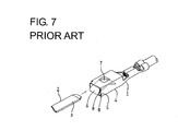
- FIG. 7 A known female terminal fitting with a resilient contact is disclosed in U.S. Pat. No. 5,235,743 and is illustrated in FIG. 7 herein.
- a female terminal fitting 1 is used with a male terminal fitting 2 that has a tab 3 at one end.
- the female terminal fitting 1 has a rectangular tubular main body 4 with a bottom wall 5 .
- a resilient contact piece 6 is folded back into the tubular main body 4 and is formed into a triangular shape with a contact 7 at the vertex of the triangle.
- a base 8 projects forward from the bottom wall 5 and a U-shaped fold 9 extends between the base 8 and the resilient contact 6 .
- the tab 3 of the male terminal fitting 2 can be inserted into the tubular main body 4 of the female terminal fitting 1 .
- the tab 3 presses the contact 7 down and deforms the resilient contact piece 6 about the fold 9 as a deformation supporting point.
- the terminal fittings 1 , 2 can be miniaturized by reducing the width and length of the tab 3 of the male terminal fitting 2 .
- the contact 7 of the resilient contact piece 6 of the female terminal fitting 1 must be moved forward to a position that conforms to the dimensions of the shorter tab 3 .
- These dimensional changes of the resilient contact piece 6 necessarily reduce the distance between the contact 7 and the fold 9 .
- the fold 9 cannot be deformed as easily and an insertion resistance of the tab 3 becomes larger.
- the invention was developed in view of the above problem and an object thereof is to enable a resilient contact piece to be deformed easily.
- the invention is a female terminal fitting with a base wall and a resilient contact piece that projects from a leading end of the base wall.
- the resilient contact piece has a contact for contacting a mating male terminal fitting.
- the mating male terminal fitting presses the contact and hence the resilient contact piece is deformed with a fold thereof as a support point.
- the resilient contact piece has at least one rigidity-lowering portion between the base of the resilient contact piece and the contact.
- the rigidity-lowering portion has a smaller cross-sectional area with respect to a direction at an angle to the longitudinal direction.
- the resilient contact piece preferably is folded back and substantially faces the base wall.
- the resilient contact piece is supported only at one end.
- the at least one rigidity-lowering portion may be provided along an area of the resilient contact piece that includes the fold.
- the mating male terminal fitting contacts the contact of the resilient contact piece.
- the resilient contact piece deforms resiliently with the fold as a supporting point.
- the resilient contact piece has the rigidity-lowering portion with a smaller cross-sectional area. Accordingly the rigidity of the resilient contact piece is reduced, and the resilient contact piece can be deformed easily.
- Miniaturized male and female terminal fittings require the contact of the female terminal fitting to be closer to the fold and, therefore, the resilient contact piece tends to be difficult to deform.
- the present invention is particularly suitable for such smaller female terminal fittings.
- the rigidity-lowering portion preferably is spaced from the fold on the resilient contact piece.
- the concentration of stress on the fold during the resilient deformation of the resilient contact piece is alleviated.
- the resilient contact piece is formed into a substantially triangular or pointed shape. More particularly, the resilient contact piece extends at an angle from the contact toward the side opposite from the fold and has an extending end that contacts the base wall as the resilient contact piece is deformed beyond a specified degree.
- the rigidity-lowering portion of the resilient contact piece is spaced from the fold and the contact. Additionally, an auxiliary rigidity-lowering portion may be provided on the resilient contact piece at a position spaced between the contact and the extending end. The auxiliary rigidity-lowering portion has a smaller cross-sectional area with respect to a direction at an angle to the longitudinal direction.
- the mating male terminal fitting presses the contact and causes the resilient contact piece to deform with the fold as a support point. Sufficient deformation about the fold brings the extending end into contact with the base wall. The resilient contact piece then is deformed with the extending end as a support point.
- the auxiliary rigidity-lowering portion and the rigidity-lowering portion enable the resilient contact piece to be deformed easily despite an increased resilient force due to the contact of the extending end with the bottom wall.
- the rigidity-lowering portion and the auxiliary rigidity-lowering portion are provided at the positions away from the fold and the contact.
- the concentration of stress on the fold and the contact during the resilient deformation of the resilient contact piece can be alleviated.
- the auxiliary rigidity-lowering portion is spaced from the extending end. As a result, a sufficient width can be ensured for the extending end to contact the base wall.
- the resilient contact piece can be supported to incline about its longitudinal axis during the resilient deformation and a contact state with the mating male terminal fitting can be stabilized.
- the rigidity-lowering portion preferably has one or more cut-away portions formed by cutting away opposite edges of the resilient contact piece.
- the cut-away portions preferably are formed in a portion of the resilient contact piece excluding the area of the contact.
- the rigidity-lowering portion may comprise one or more narrowed portions formed at an edge of the projecting base.
- the base wall preferably has at least one excessive deformation preventing portion to avoid an excessive deformation of the resilient contact piece.
- the projecting base of the base wall preferably is separated from the adjacent wall(s) by means of at least one slit.
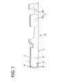
- FIG. 1 is a side view of a female terminal fitting according to a first embodiment of the present invention.
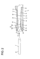
- FIG. 2 is a fragmentary side sectional view of a male terminal fitting and the female terminal fitting.
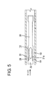
- FIG. 3 is a fragmentary sectional plan view of the female terminal fitting.
- FIG. 4 is a fragmentary side sectional view showing a state where a tab is properly held in resilient contact with a resilient contact piece.
- FIG. 5 is a fragmentary sectional plan view of a female terminal fitting according to a second embodiment of the present invention.
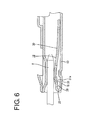
- FIG. 6 is a fragmentary side sectional view showing a state where a tab is properly held in resilient contact with a resilient contact piece.
- FIG. 7 is a perspective view of a prior art female terminal fitting.
- a female terminal fitting according to a first embodiment of the invention is identified by the numeral 10 in FIGS. 1 to 4 .
- the female terminal fitting 10 has opposite front and rear ends disposed respectively at the left and right sides of FIG. 1.
- the rear end is configured for connection with an end of a wire (not shown) and the front end is configured for mating with a mating terminal fitting M. Additionally, reference is made to FIG. 2 concerning the vertical direction.
- the female terminal fitting 10 is formed into the shape shown in FIG. 1 by bending, embossing and/or folding a substantially flat blank obtained by stamping or cutting a conductive metallic plate.
- a substantially rectangular tubular main body 11 is formed at the front end of the female terminal fitting 10 and a resilient contact piece 18 is provided in the main body 11 .
- the resilient contact piece 18 is configured for contact with a tab T of the male terminal fitting M inserted into the open front of the main body 11 .
- a barrel 12 is provided at the rear end of the female terminal fitting 10 and has front and rear pairs of opposed crimping pieces 12 a , 12 b .
- the front crimping pieces 12 a are configured to be crimped, bent or folded into connection with a core of a wire, whereas the rear crimping pieces 12 b are configured to be crimped, bent or folded into connection with an insulated portion of the wire.
- the main body 11 is comprised of a narrow and long bottom wall 13 and side walls 14 , 15 project substantially normal from the opposite side edges of the bottom wall 13 .
- a ceiling wall 16 projects from the upper end of the side wall 14 to the side wall 15 and faces the bottom wall 13 .
- An outer wall 17 projects from the upper end of the side wall 15 to the side wall 14 and is placed on or near the outer surface of the ceiling wall 16 .
- the bottom wall 13 has its front end more backward than the other walls 14 , 15 , 16 , 17 .
- a base 19 projects forward from the front end of the bottom wall 13 and is separated from the side walls 14 , 15 by slits formed at the corners between the bottom wall 13 and the side walls 14 , 15 .
- a substantially U-shaped fold 20 is folded back from the front end of the base 19 and is accommodated in the main body 11 .
- the resilient contact piece 18 is cantilevered rearwardly from the fold 20 and substantially faces the bottom wall 13 . More specifically, the resilient contact piece 18 has a front slanted portion 21 that extends rearwardly from the fold 20 and a rear slanted portion 22 that extends rearwardly from the front slanted portion 21 .
- the resilient contact piece 18 is formed into a substantially triangular or pointed shape.
- the inclination of the front slanted portion 21 relative to the bottom wall 13 is steeper than the inclination of the rear slanted portion 22 relative to the bottom wall 13 .
- the rear slanted portion 22 is longer than the front slanted portion 21 , and preferably about three times longer.
- the resilient contact piece 18 is resiliently deformable substantially along the vertical direction and the fold 20 is a deformation supporting point.
- a long narrow elliptical bulge 23 is embossed to project up from an area of the resilient contact piece 18 that extends along a longitudinal direction LD from the front slanted portion 21 to the rear slanted portion 22 .
- the bulge 23 extends from a position more forward than the middle of the front slanted portion 21 to a position near the front end of the rear slanted portion 22 .
- a guide 24 is defined on a portion of the bulge 23 that inclines up and to the back. The guide 24 is contacted slidably by the tab T and guides the deformation of the resilient contact piece 18 .
- a contact 25 is defined behind the guide 24 at the vertex or apex of the resilient contact piece 18 and resiliently contacts the tab T that has been inserted to a proper depth into the main body 11 .
- the contact 25 is more forward than the middle of the main body 11 by a specified distance in conformity with the length of the tab T to reach substantially the middle of the tab T during its insertion (see FIG. 4).
- An extending rear end 26 of the rear slanted portion 22 is spaced from the bottom wall 13 by a specified distance when the resilient contact piece 18 is in a natural state. The extending end 26 contacts the bottom wall 13 as the resilient contact piece 18 is deformed. Thus, the extending end 26 cooperates with the fold 20 to define a deformation supporting point of the resilient contact piece 18 .
- An excessive deformation preventing projection 27 is embossed to project up from the bottom wall 13 at a position facing the contact 25 from below.
- the resilient contact piece 18 engages the excessive deformation preventing projection 27 to prevent the resilient contact piece 18 from being deformed beyond its resiliency limit.
- a receiving portion 28 bulges down from the ceiling wall 16 toward the resilient contact piece 18 at a position along the longitudinal direction LD facing the bulge 23 .
- the tab T of the male terminal fitting M can be held tightly between the receiving portion 28 and the resilient contact piece 18 .
- the resilient contact piece 18 has a front and rear narrowed portions 29 and 30 , as shown in FIG. 3.
- the narrowed portions 29 , 30 are formed by cutting off the opposite side edges of the resilient contact piece 18 by a specified width that preferably is slightly more than 1 / 10 of the entire width of the resilient contact piece 18 . Accordingly, the resilient contact piece 18 has a cross-sectional area reduced along a direction substantially normal to the longitudinal direction LD at each of the two narrowed portions 29 , 30 and has a lower stiffness or rigidity to be deformed easily at these locations.
- the opposite front and rear ends of the two narrowed portions 29 , 30 are widened gradually.
- the front narrowed portion 29 is on the front slanted portion 21 of the resilient contact piece 18 and is spaced from the fold 20 and the contact 25 . Specifically, the front end of the front narrowed portion 29 is slightly backward from the fold 20 and slightly forward from the bulge 23 . The rear end of the front narrowed portion 29 is slightly forward from the contact 25 . Thus, the front narrowed portion 29 overlaps the guide 24 of the bulge 23 with respect to the longitudinal direction LD.
- the rear narrowed portion 30 is on the rear slanted portion 22 of the resilient contact piece 18 at locations spaced from the contact 25 and the extending end 26 .
- the front end of the rear narrowed portion 30 is slightly backward from the contact 25 , and the rear end thereof is slightly forward from the extending end 26 .
- the rear narrowed portion 30 is longer than the front narrowed portion 29 , and preferably about four times the length of the front narrowed portion 29 .
- the tab T of the male terminal fitting M can be inserted into the main body 11 from the front along the inserting direction ID and enters between the receiving portion 28 and the resilient contact piece 18 .
- the front end of the tab T is held in sliding contact with the forwardly inclined guide 24 of the bulge 23 .
- the resilient contact piece 18 is guided through a resilient deformation as the tab T is inserted further.
- the tab T is held in sliding contact with the guide 24 until the tab T reaches the contact 25 .
- the resilient contact piece 18 is deformed resiliently by a pressing force from the tab T, as shown in FIG. 4.
- the fold 20 is deformed to reduce its radius of curvature.
- the front slanted portion 21 and the rear slanted portion 22 including the contact 25 and the extending end portion 26 are displaced down and the extending end 26 contacts the bottom wall 13 .
- the front narrowed portion 29 located between the fold 20 and the contact 25 is deformed slightly down into a substantially arcuate shape.
- the resilient contact piece 18 is easily resiliently deformable because the front narrowed portion 29 lowers the rigidity of the resilient contact piece 18 , and the concentration of stress at the fold 20 is alleviated.
- the contact 25 is displaced down after the extending end 26 contacts the bottom wall 13 .
- a portion of the resilient contact piece 18 near the contact 25 is deformed so that the angle between the front and rear slanted portions 21 and 22 increases with the fold 20 and the extending end 26 functioning as deformation supporting points.
- the front and rear narrowed portions 29 and 30 spaced from the contact 25 are deformed down into substantially arcuate shapes.
- the extending end 26 is held in contact with the bottom wall 13 to support the resilient contact piece 18 and to increase the resilient force of the resilient contact piece 18 .
- the front and rear narrowed portions 29 and 30 decrease the rigidity of the resilient contact piece 18 , and hence the resilient contact piece 18 is easily resiliently deformable.
- the two narrowed portions 29 , 30 are spaced from the fold 20 and the contact 25 .
- the tab T inserted into the main body 11 to a proper depth is held tightly between the receiving portion 28 and the resilient contact piece 18 .
- the resilient contact piece 18 is supported by having the extending end 26 held in contact with the bottom wall 13 so as not to be inclined about its longitudinal axis. As a result, the resilient contact piece 18 is held stably in contact with the tab T.
- the front narrowed portion 29 of the resilient contact piece 18 has a smaller cross-sectional area than other portions (e.g. the contact portion 25 ) of the contact piece 18 .
- the rigidity of the resilient contact piece 18 can be made lower, and the resilient contact piece 18 can be deformed easily. Accordingly, a force required to deform the resilient contact piece 18 can be made smaller and the insertion resistance of the male terminal fitting M can be reduced.
- the front and rear narrowed portions 29 and 30 enable the resilient contact piece 18 to be deformed easily despite an increased resilient force after the extending portion 26 contacts the bottom wall 13 .
- the female terminal fitting 10 will have to be made smaller to conform to the miniaturization of the mating male terminal fitting M.
- the contact 25 must be near the fold 20 and the resilient contact piece 18 tends to be more difficult to deform resiliently.
- This embodiment is particularly suitable for such a smaller female terminal fitting 10 .
- the two narrowed portions 29 , 30 are spaced from the fold 20 and the contact 25 .
- the concentration of the stress at the fold 20 and the contact 25 during deformation the resilient contact piece 18 is alleviated.
- the resilient contact piece 18 is prevented from being damaged.
- the rear narrowed portion 30 is spaced from the extending end 26 , thereby ensuring a sufficient width of the extending end 26 for contacting the bottom wall 13 .
- the resilient contact piece 18 can be supported so as not to incline about its longitudinal axis during resilient deformation, thereby being held stably in contact with the tab T of the male terminal fitting M.
- a second embodiment of the invention is described with reference to FIGS. 5 and 6.
- a resilient contact piece 18 of the second embodiment has a narrowed base 31 at a projecting base 19 of the resilient contact piece 18 .
- the narrowed base 31 is formed by cutting off the opposite side edges of the projecting base 19 so that the width of the projecting base 19 gradually decreases toward the back of the terminal fitting 10 .
- the front end of the narrowed base 31 is slightly back from the fold 20 , and the rear end of the narrowed base 31 reaches a portion of the projecting base 19 coupled to the bottom wall 13 .
- the resilient contact piece 18 While being resiliently deformed by being pressed by a tab T, the resilient contact piece 18 is deformed resiliently by a tab T, as shown in FIG. 6, to incline back, and a rear end 31 a of the narrowed base 31 having a smallest cross-sectional area defines a supporting point. In this way, the resilient contact piece 18 is deformable more easily by providing the narrowed base 31 in addition to the narrowed front portion 29 and the narrowed rear portion 30 .
- the extending end of the resilient contact piece contacts the bottom wall during resilient deformation.
- the invention also is applicable to a resilient contact piece that resiliently deforms with only the fold as a support point without the extending end contacting the bottom wall.
- the resilient contact piece of the first embodiment has front and rear narrowed portions. However, an embodiment without the rear narrowed portion of the first embodiment also is embraced by the invention. Further, the resilient contact piece of the second embodiment has the base end narrowed portion and the front and rear narrowed portions. However, the front and rear narrowed portions may be deleted from the second embodiment according to the invention.
- each narrowed portion is formed by cutting off opposite side edges of the resilient contact piece.
- the narrowed portion may be formed by cutting off only one side edge of the resilient contact piece.
- a rigidity-lowering portion may have a smaller cross-sectional area, for example, by forming a hole in the resilient contact piece and/or by forming a recess in the resilient contact piece.
- the rigidity-lowering portion may have portions of reduced rigidity or stiffness provided by changes of the material itself, e.g. by means of heat-treatment, tempering, forging, irradiation, chemical and/or nuclear reactions, etc.
- the front and rear narrowed portions are spaced from the fold, the contact and the extending end in the foregoing embodiments. However, they may be placed one over another in accordance with the present invention.
- the female terminal fitting is connected with the wire by crimping in the foregoing embodiments.
- the invention is also applicable to a female terminal fitting connected with a wire by other means such as insulation displacement, soldering or the like.
Landscapes
- Coupling Device And Connection With Printed Circuit (AREA)
Abstract
A female terminal fitting (10) has a tubular main body (11) with front and rear ends and a bottom wall (13). A fold (20) is folded back from the front end of the bottom wall (13) and a resilient contact piece (18) extends back from the fold (20) to face the bottom wall (13). A bulge (23) on the resilient contact piece (18) includes a contact (25) for contacting a tab (T) of a male terminal fitting (M). The contact (25) is pressed by the tab (T) so that the resilient contact piece (18) is deformed with the fold (20) as a supporting point and an extending end (26) thereof contacts the bottom wall (13). The resilient contact piece (18) has a front narrowed portion (29) between the fold (20) and the contact (25) and a rear narrowed portion 30 between the contact (25) and the extending end (26).
Description
- 1. Field of the Invention
- The invention relates to a female terminal fitting with a resilient contact.
- 2. Description of the Related Art
- A known female terminal fitting with a resilient contact is disclosed in U.S. Pat. No. 5,235,743 and is illustrated in FIG. 7 herein. With reference to FIG. 7, a female terminal fitting 1 is used with a
male terminal fitting 2 that has atab 3 at one end. The female terminal fitting 1 has a rectangular tubularmain body 4 with a bottom wall 5. A resilient contact piece 6 is folded back into the tubularmain body 4 and is formed into a triangular shape with acontact 7 at the vertex of the triangle. A base 8 projects forward from the bottom wall 5 and a U-shaped fold 9 extends between the base 8 and the resilient contact 6. Thetab 3 of themale terminal fitting 2 can be inserted into the tubularmain body 4 of the female terminal fitting 1. Thus, thetab 3 presses thecontact 7 down and deforms the resilient contact piece 6 about the fold 9 as a deformation supporting point. - The
terminal fittings 1, 2 can be miniaturized by reducing the width and length of thetab 3 of the male terminal fitting 2. However, thecontact 7 of the resilient contact piece 6 of the female terminal fitting 1 must be moved forward to a position that conforms to the dimensions of theshorter tab 3. These dimensional changes of the resilient contact piece 6 necessarily reduce the distance between thecontact 7 and the fold 9. Thus, the fold 9 cannot be deformed as easily and an insertion resistance of thetab 3 becomes larger. - The invention was developed in view of the above problem and an object thereof is to enable a resilient contact piece to be deformed easily.
- The invention is a female terminal fitting with a base wall and a resilient contact piece that projects from a leading end of the base wall. The resilient contact piece has a contact for contacting a mating male terminal fitting. The mating male terminal fitting presses the contact and hence the resilient contact piece is deformed with a fold thereof as a support point. The resilient contact piece has at least one rigidity-lowering portion between the base of the resilient contact piece and the contact. The rigidity-lowering portion has a smaller cross-sectional area with respect to a direction at an angle to the longitudinal direction.
- The resilient contact piece preferably is folded back and substantially faces the base wall.
- Preferably, the resilient contact piece is supported only at one end.
- The at least one rigidity-lowering portion may be provided along an area of the resilient contact piece that includes the fold.
- The mating male terminal fitting contacts the contact of the resilient contact piece. Thus, the resilient contact piece deforms resiliently with the fold as a supporting point. The resilient contact piece has the rigidity-lowering portion with a smaller cross-sectional area. Accordingly the rigidity of the resilient contact piece is reduced, and the resilient contact piece can be deformed easily.
- Miniaturized male and female terminal fittings require the contact of the female terminal fitting to be closer to the fold and, therefore, the resilient contact piece tends to be difficult to deform. The present invention is particularly suitable for such smaller female terminal fittings.
- The rigidity-lowering portion preferably is spaced from the fold on the resilient contact piece. Thus, the concentration of stress on the fold during the resilient deformation of the resilient contact piece is alleviated.
- The resilient contact piece is formed into a substantially triangular or pointed shape. More particularly, the resilient contact piece extends at an angle from the contact toward the side opposite from the fold and has an extending end that contacts the base wall as the resilient contact piece is deformed beyond a specified degree. The rigidity-lowering portion of the resilient contact piece is spaced from the fold and the contact. Additionally, an auxiliary rigidity-lowering portion may be provided on the resilient contact piece at a position spaced between the contact and the extending end. The auxiliary rigidity-lowering portion has a smaller cross-sectional area with respect to a direction at an angle to the longitudinal direction.
- The mating male terminal fitting presses the contact and causes the resilient contact piece to deform with the fold as a support point. Sufficient deformation about the fold brings the extending end into contact with the base wall. The resilient contact piece then is deformed with the extending end as a support point. The auxiliary rigidity-lowering portion and the rigidity-lowering portion enable the resilient contact piece to be deformed easily despite an increased resilient force due to the contact of the extending end with the bottom wall.
- The rigidity-lowering portion and the auxiliary rigidity-lowering portion are provided at the positions away from the fold and the contact. Thus, the concentration of stress on the fold and the contact during the resilient deformation of the resilient contact piece can be alleviated.
- The auxiliary rigidity-lowering portion is spaced from the extending end. As a result, a sufficient width can be ensured for the extending end to contact the base wall. Thus, the resilient contact piece can be supported to incline about its longitudinal axis during the resilient deformation and a contact state with the mating male terminal fitting can be stabilized.
- The rigidity-lowering portion preferably has one or more cut-away portions formed by cutting away opposite edges of the resilient contact piece. The cut-away portions preferably are formed in a portion of the resilient contact piece excluding the area of the contact.
- The rigidity-lowering portion may comprise one or more narrowed portions formed at an edge of the projecting base.
- The base wall preferably has at least one excessive deformation preventing portion to avoid an excessive deformation of the resilient contact piece.
- The projecting base of the base wall preferably is separated from the adjacent wall(s) by means of at least one slit.
- These and other objects, features and advantages of the present invention will become more apparent upon reading of the following detailed description of preferred embodiments and accompanying drawings. It should be understood that even though embodiments are separately described, single features thereof may be combined to additional embodiments.
- FIG. 1 is a side view of a female terminal fitting according to a first embodiment of the present invention.
- FIG. 2 is a fragmentary side sectional view of a male terminal fitting and the female terminal fitting.
- FIG. 3 is a fragmentary sectional plan view of the female terminal fitting.
- FIG. 4 is a fragmentary side sectional view showing a state where a tab is properly held in resilient contact with a resilient contact piece.
- FIG. 5 is a fragmentary sectional plan view of a female terminal fitting according to a second embodiment of the present invention.
- FIG. 6 is a fragmentary side sectional view showing a state where a tab is properly held in resilient contact with a resilient contact piece.
- FIG. 7 is a perspective view of a prior art female terminal fitting.
- A female terminal fitting according to a first embodiment of the invention is identified by the numeral 10 in FIGS. 1 to 4. The female terminal fitting 10 has opposite front and rear ends disposed respectively at the left and right sides of FIG. 1. The rear end is configured for connection with an end of a wire (not shown) and the front end is configured for mating with a mating terminal fitting M. Additionally, reference is made to FIG. 2 concerning the vertical direction.
- The female terminal fitting 10 is formed into the shape shown in FIG. 1 by bending, embossing and/or folding a substantially flat blank obtained by stamping or cutting a conductive metallic plate. A substantially rectangular tubular
main body 11 is formed at the front end of the female terminal fitting 10 and aresilient contact piece 18 is provided in themain body 11. Theresilient contact piece 18 is configured for contact with a tab T of the male terminal fitting M inserted into the open front of themain body 11. Abarrel 12 is provided at the rear end of the female terminal fitting 10 and has front and rear pairs of opposed crimpingpieces pieces 12 a are configured to be crimped, bent or folded into connection with a core of a wire, whereas therear crimping pieces 12 b are configured to be crimped, bent or folded into connection with an insulated portion of the wire. - The
main body 11 is comprised of a narrow andlong bottom wall 13 andside walls bottom wall 13. Aceiling wall 16 projects from the upper end of theside wall 14 to theside wall 15 and faces thebottom wall 13. Anouter wall 17 projects from the upper end of theside wall 15 to theside wall 14 and is placed on or near the outer surface of theceiling wall 16. As shown in FIGS. 2 and 3, thebottom wall 13 has its front end more backward than theother walls - A base 19 projects forward from the front end of the
bottom wall 13 and is separated from theside walls bottom wall 13 and theside walls U-shaped fold 20 is folded back from the front end of thebase 19 and is accommodated in themain body 11. Theresilient contact piece 18 is cantilevered rearwardly from thefold 20 and substantially faces thebottom wall 13. More specifically, theresilient contact piece 18 has a front slantedportion 21 that extends rearwardly from thefold 20 and a rear slantedportion 22 that extends rearwardly from the front slantedportion 21. Thus, theresilient contact piece 18 is formed into a substantially triangular or pointed shape. The inclination of the front slantedportion 21 relative to thebottom wall 13 is steeper than the inclination of the rear slantedportion 22 relative to thebottom wall 13. The rear slantedportion 22 is longer than the front slantedportion 21, and preferably about three times longer. Theresilient contact piece 18 is resiliently deformable substantially along the vertical direction and thefold 20 is a deformation supporting point. - A long narrow
elliptical bulge 23 is embossed to project up from an area of theresilient contact piece 18 that extends along a longitudinal direction LD from the front slantedportion 21 to the rear slantedportion 22. Specifically, thebulge 23 extends from a position more forward than the middle of the front slantedportion 21 to a position near the front end of the rear slantedportion 22. Aguide 24 is defined on a portion of thebulge 23 that inclines up and to the back. Theguide 24 is contacted slidably by the tab T and guides the deformation of theresilient contact piece 18. Acontact 25 is defined behind theguide 24 at the vertex or apex of theresilient contact piece 18 and resiliently contacts the tab T that has been inserted to a proper depth into themain body 11. Thecontact 25 is more forward than the middle of themain body 11 by a specified distance in conformity with the length of the tab T to reach substantially the middle of the tab T during its insertion (see FIG. 4). An extendingrear end 26 of the rear slantedportion 22 is spaced from thebottom wall 13 by a specified distance when theresilient contact piece 18 is in a natural state. The extendingend 26 contacts thebottom wall 13 as theresilient contact piece 18 is deformed. Thus, the extendingend 26 cooperates with thefold 20 to define a deformation supporting point of theresilient contact piece 18. - An excessive
deformation preventing projection 27 is embossed to project up from thebottom wall 13 at a position facing thecontact 25 from below. Theresilient contact piece 18 engages the excessivedeformation preventing projection 27 to prevent theresilient contact piece 18 from being deformed beyond its resiliency limit. A receivingportion 28 bulges down from theceiling wall 16 toward theresilient contact piece 18 at a position along the longitudinal direction LD facing thebulge 23. Thus, the tab T of the male terminal fitting M can be held tightly between the receivingportion 28 and theresilient contact piece 18. - The
resilient contact piece 18 has a front and rear narrowedportions portions resilient contact piece 18 by a specified width that preferably is slightly more than 1/10 of the entire width of theresilient contact piece 18. Accordingly, theresilient contact piece 18 has a cross-sectional area reduced along a direction substantially normal to the longitudinal direction LD at each of the two narrowedportions portions - The front narrowed
portion 29 is on the front slantedportion 21 of theresilient contact piece 18 and is spaced from thefold 20 and thecontact 25. Specifically, the front end of the front narrowedportion 29 is slightly backward from thefold 20 and slightly forward from thebulge 23. The rear end of the front narrowedportion 29 is slightly forward from thecontact 25. Thus, the front narrowedportion 29 overlaps theguide 24 of thebulge 23 with respect to the longitudinal direction LD. On the other hand, the rear narrowedportion 30 is on the rear slantedportion 22 of theresilient contact piece 18 at locations spaced from thecontact 25 and the extendingend 26. Specifically, the front end of the rear narrowedportion 30 is slightly backward from thecontact 25, and the rear end thereof is slightly forward from the extendingend 26. The rear narrowedportion 30 is longer than the front narrowedportion 29, and preferably about four times the length of the front narrowedportion 29. - The tab T of the male terminal fitting M can be inserted into the
main body 11 from the front along the inserting direction ID and enters between the receivingportion 28 and theresilient contact piece 18. The front end of the tab T is held in sliding contact with the forwardlyinclined guide 24 of thebulge 23. Thus, theresilient contact piece 18 is guided through a resilient deformation as the tab T is inserted further. - The tab T is held in sliding contact with the
guide 24 until the tab T reaches thecontact 25. Thus, theresilient contact piece 18 is deformed resiliently by a pressing force from the tab T, as shown in FIG. 4. At this time, thefold 20 is deformed to reduce its radius of curvature. Thus, the front slantedportion 21 and the rear slantedportion 22 including thecontact 25 and the extendingend portion 26 are displaced down and the extendingend 26 contacts thebottom wall 13. In this process, the front narrowedportion 29 located between thefold 20 and thecontact 25 is deformed slightly down into a substantially arcuate shape. Theresilient contact piece 18 is easily resiliently deformable because the front narrowedportion 29 lowers the rigidity of theresilient contact piece 18, and the concentration of stress at thefold 20 is alleviated. - The
contact 25 is displaced down after the extendingend 26 contacts thebottom wall 13. As a result, a portion of theresilient contact piece 18 near thecontact 25 is deformed so that the angle between the front and rearslanted portions fold 20 and the extendingend 26 functioning as deformation supporting points. In this process, the front and rear narrowedportions contact 25 are deformed down into substantially arcuate shapes. At this time, the extendingend 26 is held in contact with thebottom wall 13 to support theresilient contact piece 18 and to increase the resilient force of theresilient contact piece 18. However, the front and rear narrowedportions resilient contact piece 18, and hence theresilient contact piece 18 is easily resiliently deformable. Further, the two narrowedportions fold 20 and thecontact 25. Thus, stress resulting from the resilient deformation is distributed over substantially the entireresilient contact piece 18 to alleviate the concentration of the stress at thefold 20 and thecontact 25. - As described above, the tab T inserted into the
main body 11 to a proper depth is held tightly between the receivingportion 28 and theresilient contact piece 18. At this time, theresilient contact piece 18 is supported by having the extendingend 26 held in contact with thebottom wall 13 so as not to be inclined about its longitudinal axis. As a result, theresilient contact piece 18 is held stably in contact with the tab T. - The front narrowed
portion 29 of theresilient contact piece 18 has a smaller cross-sectional area than other portions (e.g. the contact portion 25) of thecontact piece 18. Thus, the rigidity of theresilient contact piece 18 can be made lower, and theresilient contact piece 18 can be deformed easily. Accordingly, a force required to deform theresilient contact piece 18 can be made smaller and the insertion resistance of the male terminal fitting M can be reduced. Further, the front and rear narrowedportions resilient contact piece 18 to be deformed easily despite an increased resilient force after the extendingportion 26 contacts thebottom wall 13. - The female terminal fitting 10 will have to be made smaller to conform to the miniaturization of the mating male terminal fitting M. Thus, the
contact 25 must be near thefold 20 and theresilient contact piece 18 tends to be more difficult to deform resiliently. This embodiment is particularly suitable for such a smaller female terminal fitting 10. - The two narrowed
portions fold 20 and thecontact 25. Thus, the concentration of the stress at thefold 20 and thecontact 25 during deformation theresilient contact piece 18 is alleviated. As a result theresilient contact piece 18 is prevented from being damaged. - The rear narrowed
portion 30 is spaced from the extendingend 26, thereby ensuring a sufficient width of the extendingend 26 for contacting thebottom wall 13. Thus, theresilient contact piece 18 can be supported so as not to incline about its longitudinal axis during resilient deformation, thereby being held stably in contact with the tab T of the male terminal fitting M. - A second embodiment of the invention is described with reference to FIGS. 5 and 6. A
resilient contact piece 18 of the second embodiment has a narrowedbase 31 at a projectingbase 19 of theresilient contact piece 18. The narrowedbase 31 is formed by cutting off the opposite side edges of the projectingbase 19 so that the width of the projectingbase 19 gradually decreases toward the back of theterminal fitting 10. The front end of the narrowedbase 31 is slightly back from thefold 20, and the rear end of the narrowedbase 31 reaches a portion of the projectingbase 19 coupled to thebottom wall 13. - While being resiliently deformed by being pressed by a tab T, the
resilient contact piece 18 is deformed resiliently by a tab T, as shown in FIG. 6, to incline back, and arear end 31 a of the narrowedbase 31 having a smallest cross-sectional area defines a supporting point. In this way, theresilient contact piece 18 is deformable more easily by providing the narrowedbase 31 in addition to the narrowedfront portion 29 and the narrowedrear portion 30. - Other elements are similar to the first embodiment. These elements are denoted by the same reference numerals, but are not described again.
- The invention is not limited to the above described and illustrated embodiments. For example, the following embodiments also are embraced by the technical scope of the invention as defined by the claims. Beside the following embodiments, various changes can be made without departing from the scope and spirit of the present invention as defined by the claims.
- In the foregoing embodiments, the extending end of the resilient contact piece contacts the bottom wall during resilient deformation. However, the invention also is applicable to a resilient contact piece that resiliently deforms with only the fold as a support point without the extending end contacting the bottom wall.
- The resilient contact piece of the first embodiment has front and rear narrowed portions. However, an embodiment without the rear narrowed portion of the first embodiment also is embraced by the invention. Further, the resilient contact piece of the second embodiment has the base end narrowed portion and the front and rear narrowed portions. However, the front and rear narrowed portions may be deleted from the second embodiment according to the invention.
- In the foregoing embodiments, each narrowed portion is formed by cutting off opposite side edges of the resilient contact piece. However, the narrowed portion may be formed by cutting off only one side edge of the resilient contact piece. Further, a rigidity-lowering portion may have a smaller cross-sectional area, for example, by forming a hole in the resilient contact piece and/or by forming a recess in the resilient contact piece. Additionally or alternatively, the rigidity-lowering portion may have portions of reduced rigidity or stiffness provided by changes of the material itself, e.g. by means of heat-treatment, tempering, forging, irradiation, chemical and/or nuclear reactions, etc.
- The front and rear narrowed portions are spaced from the fold, the contact and the extending end in the foregoing embodiments. However, they may be placed one over another in accordance with the present invention.
- The female terminal fitting is connected with the wire by crimping in the foregoing embodiments. However, the invention is also applicable to a female terminal fitting connected with a wire by other means such as insulation displacement, soldering or the like.
Claims (13)
1. A female terminal fitting (10), comprising:
a base wall (13) having front and rear ends;
a projecting base (19) projecting from the front end of the base wall (13);
a fold (20) folded back from the projecting base (19); and
a resilient contact piece (18) projecting back along a longitudinal direction (LD) from the fold (20) and being resiliently deformable with the fold (20) as a support point, the resilient contact piece (18) having a contact (25) disposed for contact with a mating male terminal fitting (M), at least one rigidity-lowering portion (29; 31) being provided on the resilient contact piece (18) in an area defined between the projecting base (19) and the contact (25), the rigidity-lowering portion (29; 31) having a reduced cross-sectional area with respect to a direction at an angle to the longitudinal direction (LD).
2. The female terminal fitting of claim 1 , wherein the resilient contact piece (18) substantially faces the base wall (13).
3. The female terminal fitting of claim 1 , wherein the resilient contact piece (18) in an unbiased condition is supported only at one end.
4. The female terminal fitting of claim 1 , wherein the rigidity-lowering portion (29; 31) is spaced from the fold (20).
5. The female terminal fitting of claim 1 , wherein the resilient contact piece (18) is formed into a substantially triangular shape and extends at an angle from the contact (25) toward an end of the resilient contact (18) opposite from the fold (20) and has an extending end (26) which contacts the base wall (13) as the resilient contact piece (18) is deformed beyond a specified degree.
6. The female terminal fitting of claim 5 , wherein the rigidity-lowering portion (19) is spaced from both the fold (20) and the contact (25).
7. The female terminal fitting of claim 6 , wherein an auxiliary rigidity-lowering portion (30) is provided on the resilient contact piece (18) rearward from the contact (25), the auxiliary rigidity-lowering portion (30) having a reduced cross-sectional area with respect to an angle to the longitudinal direction (LD).
8. The female terminal fitting of claim 7 , wherein the auxiliary rigidity-lowering portion (30) is spaced from both the contact (25) and the extending end (26).
9. The female terminal fitting of claim 1 , wherein the rigidity-lowering portion (29; 31) comprises cut-away portions (29) formed by cutting away substantially opposite edges of the resilient contact piece (18).
10. The female terminal fitting of claim 9 , wherein the cut-away portions (29) are formed in portions of the resilient contact piece (18) excluding the contact (25).
11. The female terminal fitting of claim 1 , wherein the rigidity-lowering portion (29; 31) further comprises at least one narrowed portion (31) formed at an edge of the projecting base (19).
12. The female terminal fitting of claim 1 , wherein the base wall (13) comprises at least one excessive deformation preventing portion (27) for avoiding an excessive deformation of the resilient contact piece (18).
13. The female terminal fitting of claim 1 , wherein the projecting base (19) is at least partly separated from the adjacent wall(s) (14, 15) by at least one slit.
Applications Claiming Priority (2)
| Application Number | Priority Date | Filing Date | Title |
|---|---|---|---|
| JP2002-101042 | 2002-04-03 | ||
| JP2002101042A JP3767506B2 (en) | 2002-04-03 | 2002-04-03 | Female terminal fitting |
Publications (2)
| Publication Number | Publication Date |
|---|---|
| US20030190847A1 true US20030190847A1 (en) | 2003-10-09 |
| US6790100B2 US6790100B2 (en) | 2004-09-14 |
Family
ID=28672090
Family Applications (1)
| Application Number | Title | Priority Date | Filing Date |
|---|---|---|---|
| US10/405,260 Expired - Lifetime US6790100B2 (en) | 2002-04-03 | 2003-04-01 | Female terminal fitting |
Country Status (3)
| Country | Link |
|---|---|
| US (1) | US6790100B2 (en) |
| JP (1) | JP3767506B2 (en) |
| DE (1) | DE10313921B4 (en) |
Cited By (6)
| Publication number | Priority date | Publication date | Assignee | Title |
|---|---|---|---|---|
| US20160006143A1 (en) * | 2013-02-19 | 2016-01-07 | Sumitomo Wiring Systems, Ltd. | Female terminal fitting |
| US20160013569A1 (en) * | 2013-03-05 | 2016-01-14 | Sumitomo Wiring Systems, Ltd. | Female terminal fitting |
| CN105765796A (en) * | 2013-11-26 | 2016-07-13 | 矢崎总业株式会社 | Connection terminal |
| US10476190B2 (en) | 2016-05-12 | 2019-11-12 | Sumitomo Wiring Systems, Ltd. | Terminal fitting |
| CN112305275A (en) * | 2020-11-25 | 2021-02-02 | 国网福建省电力有限公司 | 10kV cubical switchboard generating line withstand voltage test wiring instrument |
| US12500364B2 (en) * | 2020-09-21 | 2025-12-16 | Molex, Llc | Anti-wear female receptacle terminal |
Families Citing this family (9)
| Publication number | Priority date | Publication date | Assignee | Title |
|---|---|---|---|---|
| US7537497B2 (en) * | 2005-09-26 | 2009-05-26 | Fci Americas Technology, Inc. | Multi-piece electrical receptacle terminal |
| JP5251819B2 (en) * | 2009-10-09 | 2013-07-31 | 住友電装株式会社 | Female terminal bracket |
| JP5958394B2 (en) * | 2013-03-21 | 2016-08-02 | 住友電装株式会社 | Terminal fitting |
| JP6269309B2 (en) * | 2014-05-14 | 2018-01-31 | 住友電装株式会社 | Female terminal |
| US9941615B2 (en) | 2015-08-05 | 2018-04-10 | Yazaki Corporation | Terminal and connector |
| JP6211564B2 (en) * | 2015-08-05 | 2017-10-11 | 矢崎総業株式会社 | Terminals and connectors |
| JP7472828B2 (en) * | 2021-03-10 | 2024-04-23 | 住友電装株式会社 | Terminals |
| JP7549782B2 (en) | 2021-06-15 | 2024-09-12 | 株式会社オートネットワーク技術研究所 | Terminal fittings and chain terminals |
| JP2025012471A (en) * | 2023-07-13 | 2025-01-24 | 株式会社オートネットワーク技術研究所 | Terminals and Connectors |
Citations (3)
| Publication number | Priority date | Publication date | Assignee | Title |
|---|---|---|---|---|
| US5269712A (en) * | 1992-11-06 | 1993-12-14 | The Whitaker Corporation | Low-force receptacle contact and method of making same |
| US5443592A (en) * | 1993-10-26 | 1995-08-22 | Connecteurs Cinch | Female electrical contact member |
| US6293833B1 (en) * | 2001-01-05 | 2001-09-25 | Yazaki North America | Low insertion force, high contact force terminal spring |
Family Cites Families (9)
| Publication number | Priority date | Publication date | Assignee | Title |
|---|---|---|---|---|
| US4717356A (en) * | 1986-04-10 | 1988-01-05 | United Technologies Automotive, Inc. | Electrical receptacle terminal |
| JPS6356572U (en) * | 1986-09-30 | 1988-04-15 | ||
| US5235743A (en) | 1990-07-11 | 1993-08-17 | Yazaki Corporation | Method of manufacturing a pair of terminals having a low friction material on a mating surface to facilitate connection of the terminals |
| JP2916001B2 (en) * | 1990-07-11 | 1999-07-05 | 矢崎総業株式会社 | Manufacturing method of low insertion force terminal |
| JP2596913Y2 (en) * | 1993-12-24 | 1999-06-28 | 日本エー・エム・ピー株式会社 | Female terminal |
| JP3533536B2 (en) * | 1994-07-11 | 2004-05-31 | 住友電装株式会社 | Female terminal fitting |
| JPH0945404A (en) * | 1995-07-28 | 1997-02-14 | Yazaki Corp | Female terminal |
| JP3529026B2 (en) * | 1998-04-15 | 2004-05-24 | 矢崎総業株式会社 | Female terminal |
| JP3875526B2 (en) * | 2001-08-10 | 2007-01-31 | 矢崎総業株式会社 | Terminal spring structure |
-
2002
- 2002-04-03 JP JP2002101042A patent/JP3767506B2/en not_active Expired - Lifetime
-
2003
- 2003-03-27 DE DE10313921A patent/DE10313921B4/en not_active Expired - Lifetime
- 2003-04-01 US US10/405,260 patent/US6790100B2/en not_active Expired - Lifetime
Patent Citations (3)
| Publication number | Priority date | Publication date | Assignee | Title |
|---|---|---|---|---|
| US5269712A (en) * | 1992-11-06 | 1993-12-14 | The Whitaker Corporation | Low-force receptacle contact and method of making same |
| US5443592A (en) * | 1993-10-26 | 1995-08-22 | Connecteurs Cinch | Female electrical contact member |
| US6293833B1 (en) * | 2001-01-05 | 2001-09-25 | Yazaki North America | Low insertion force, high contact force terminal spring |
Cited By (9)
| Publication number | Priority date | Publication date | Assignee | Title |
|---|---|---|---|---|
| US20160006143A1 (en) * | 2013-02-19 | 2016-01-07 | Sumitomo Wiring Systems, Ltd. | Female terminal fitting |
| US9431723B2 (en) * | 2013-02-19 | 2016-08-30 | Sumitomo Wiring Systems, Ltd. | Female terminal fitting |
| US20160013569A1 (en) * | 2013-03-05 | 2016-01-14 | Sumitomo Wiring Systems, Ltd. | Female terminal fitting |
| US9515396B2 (en) * | 2013-03-05 | 2016-12-06 | Sumitomo Wiring Systems, Ltd. | Female terminal fitting |
| CN105765796A (en) * | 2013-11-26 | 2016-07-13 | 矢崎总业株式会社 | Connection terminal |
| US10476190B2 (en) | 2016-05-12 | 2019-11-12 | Sumitomo Wiring Systems, Ltd. | Terminal fitting |
| US10847913B2 (en) | 2016-05-12 | 2020-11-24 | Sumitomo Wiring Systems, Ltd. | Terminal fitting |
| US12500364B2 (en) * | 2020-09-21 | 2025-12-16 | Molex, Llc | Anti-wear female receptacle terminal |
| CN112305275A (en) * | 2020-11-25 | 2021-02-02 | 国网福建省电力有限公司 | 10kV cubical switchboard generating line withstand voltage test wiring instrument |
Also Published As
| Publication number | Publication date |
|---|---|
| JP2003297470A (en) | 2003-10-17 |
| JP3767506B2 (en) | 2006-04-19 |
| DE10313921A1 (en) | 2003-11-06 |
| US6790100B2 (en) | 2004-09-14 |
| DE10313921B4 (en) | 2008-07-17 |
Similar Documents
| Publication | Publication Date | Title |
|---|---|---|
| EP1351338B1 (en) | A terminal fitting | |
| US7938695B2 (en) | Terminal fitting | |
| US6736684B2 (en) | Terminal fitting and method of forming it | |
| US8795007B2 (en) | Terminal fitting | |
| US7094114B2 (en) | Female terminal fitting and method of assembling such terminal fitting | |
| US6790100B2 (en) | Female terminal fitting | |
| US7144281B2 (en) | Female terminal fitting and a blank for a plurality of terminal fittings | |
| US7347747B2 (en) | Terminal fitting with a resilient reinforcing piece | |
| US8998656B2 (en) | Terminal fitting having auxiliary spring with support | |
| CN1653650B (en) | connection terminal | |
| US5716245A (en) | Female terminal | |
| JPH0945401A (en) | Female type contact | |
| US6851989B2 (en) | Terminal fitting with plural resilient contact pieces and pressing portion for holding base ends of resilient contact pieces together | |
| US8523619B2 (en) | Terminal fitting | |
| US6790105B2 (en) | Male terminal fitting | |
| US8454394B2 (en) | Terminal fitting having an auxilary resilient piece | |
| US6790106B2 (en) | Male terminal fitting and method of forming it | |
| US6948986B2 (en) | Connector | |
| US6585544B2 (en) | Terminal fitting | |
| US6319076B1 (en) | Socket contact element | |
| US20090117773A1 (en) | Terminal fitting | |
| JPH09232021A (en) | Female electric terminal | |
| EP1689036B1 (en) | A terminal fitting, a connector provided therewith and a method of forming a terminal fitting | |
| EP1811608B1 (en) | A terminal fitting and connector provided therewith | |
| US6464548B2 (en) | Female terminal fitting |
Legal Events
| Date | Code | Title | Description |
|---|---|---|---|
| AS | Assignment |
Owner name: SUMITOMO WIRING SYSTEMS LTD, JAPAN Free format text: ASSIGNMENT OF ASSIGNORS INTEREST;ASSIGNORS:NANKOU, YUUICHI;FUKATSU, YUKIHIRO;KAWASE, HAJIME;REEL/FRAME:013938/0624 Effective date: 20030325 |
|
| STCF | Information on status: patent grant |
Free format text: PATENTED CASE |
|
| FEPP | Fee payment procedure |
Free format text: PAYOR NUMBER ASSIGNED (ORIGINAL EVENT CODE: ASPN); ENTITY STATUS OF PATENT OWNER: LARGE ENTITY |
|
| FPAY | Fee payment |
Year of fee payment: 4 |
|
| FPAY | Fee payment |
Year of fee payment: 8 |
|
| FPAY | Fee payment |
Year of fee payment: 12 |