EP2309216A2 - Device and method for cooling products - Google Patents
Device and method for cooling products Download PDFInfo
- Publication number
- EP2309216A2 EP2309216A2 EP20100170553 EP10170553A EP2309216A2 EP 2309216 A2 EP2309216 A2 EP 2309216A2 EP 20100170553 EP20100170553 EP 20100170553 EP 10170553 A EP10170553 A EP 10170553A EP 2309216 A2 EP2309216 A2 EP 2309216A2
- Authority
- EP
- European Patent Office
- Prior art keywords
- nozzle
- nozzles
- treatment
- flow
- nozzle plate
- Prior art date
- Legal status (The legal status is an assumption and is not a legal conclusion. Google has not performed a legal analysis and makes no representation as to the accuracy of the status listed.)
- Withdrawn
Links
Images


Classifications
-
- F—MECHANICAL ENGINEERING; LIGHTING; HEATING; WEAPONS; BLASTING
- F25—REFRIGERATION OR COOLING; COMBINED HEATING AND REFRIGERATION SYSTEMS; HEAT PUMP SYSTEMS; MANUFACTURE OR STORAGE OF ICE; LIQUEFACTION SOLIDIFICATION OF GASES
- F25D—REFRIGERATORS; COLD ROOMS; ICE-BOXES; COOLING OR FREEZING APPARATUS NOT OTHERWISE PROVIDED FOR
- F25D17/00—Arrangements for circulating cooling fluids; Arrangements for circulating gas, e.g. air, within refrigerated spaces
- F25D17/005—Arrangements for circulating cooling fluids; Arrangements for circulating gas, e.g. air, within refrigerated spaces in cold rooms
-
- F—MECHANICAL ENGINEERING; LIGHTING; HEATING; WEAPONS; BLASTING
- F25—REFRIGERATION OR COOLING; COMBINED HEATING AND REFRIGERATION SYSTEMS; HEAT PUMP SYSTEMS; MANUFACTURE OR STORAGE OF ICE; LIQUEFACTION SOLIDIFICATION OF GASES
- F25D—REFRIGERATORS; COLD ROOMS; ICE-BOXES; COOLING OR FREEZING APPARATUS NOT OTHERWISE PROVIDED FOR
- F25D17/00—Arrangements for circulating cooling fluids; Arrangements for circulating gas, e.g. air, within refrigerated spaces
- F25D17/04—Arrangements for circulating cooling fluids; Arrangements for circulating gas, e.g. air, within refrigerated spaces for circulating air, e.g. by convection
- F25D17/042—Air treating means within refrigerated spaces
- F25D17/045—Air flow control arrangements
-
- F—MECHANICAL ENGINEERING; LIGHTING; HEATING; WEAPONS; BLASTING
- F25—REFRIGERATION OR COOLING; COMBINED HEATING AND REFRIGERATION SYSTEMS; HEAT PUMP SYSTEMS; MANUFACTURE OR STORAGE OF ICE; LIQUEFACTION SOLIDIFICATION OF GASES
- F25B—REFRIGERATION MACHINES, PLANTS OR SYSTEMS; COMBINED HEATING AND REFRIGERATION SYSTEMS; HEAT PUMP SYSTEMS
- F25B2600/00—Control issues
- F25B2600/11—Fan speed control
- F25B2600/112—Fan speed control of evaporator fans
Definitions
- the invention relates to a treatment device and a method for cooling products with a gaseous treatment medium, preferably air, with a blower arrangement for generating a flow of the treatment medium, at least one cooling device, at least one nozzle plate having a plurality of openings in the form of nozzles or nozzle groups , For generating individual working flows of the treatment medium and at least one of the nozzle plate upstream treatment station, for the product stack to be treated, which can be acted upon by the nozzle or nozzle groups of the nozzle plate with the treatment medium.
- a gaseous treatment medium preferably air
- Such treatment devices are used, for example, food products, eg. B. Milk products to cool after the manufacturing process. While the products pass through the treatment device, they are treated with defined climatic conditions, for example by flowing around with cool air to cool them to a predetermined, suitable for subsequent storage temperature.
- the products to be treated are stacked on pallets to product stack and retracted into the treatment device, so that a large number of such products can be treated simultaneously.
- Such a treatment device or cooling tunnel is from the DE 100 17 408 A1 known.
- the product stack is transported past for cooling on vertically arranged nozzle plates, which blow cold air horizontally through the product layers.
- the cooling capacity, the cooling tunnel length and the transport speed through the tunnel are designed so that the desired cooling of the products is achieved.
- the discontinuous mode of operation as in the EP 1 455 151 A1 disclosed.
- the products to be cooled are deposited at a treatment position and blown there with cold air until the desired cooling is achieved. Subsequently, the product stacks are moved out of the cooling tunnel.
- the nozzle plate consists of a plurality of separate inlet nozzles through which a plurality of defined inflow points is formed over the inflow region, into which the gaseous treatment medium flows on the one hand with a defined direction and on the other with a defined speed.
- the inflow velocity which has the gaseous treatment medium in the outlet region of the inlet nozzles, is preferably in the range of 20-25 m / s.
- Such a high inflow velocity ensures that, also due to the relatively concentrated beams of incoming gaseous treatment medium, even the smallest gaps between the individual products to be treated or smallest openings in packaging materials containing these products, for example cardboard, are flowed through.
- the treatment medium thus also approaches these products in the inner volume range of the products stacked on the pallets and can contribute to their treatment, for example their cooling.
- a disadvantage of this type of cooling tunnels and nozzle plate is that no adaptation to the pallet loading takes place and so the energy requirements for the pressure supply device for generating the required flow rate at not fully loaded pallets is almost as high as in fully loaded pallets.
- the invention is therefore based on the object to provide a treatment device with a higher energy efficiency, which allows adaptation to the pallet load.
- a treatment device for cooling products with a gaseous treatment medium is proposed.
- the treatment medium is preferably ambient air, which generates a circular base flow in the treatment device by means of a blower arrangement for generating a flow of the treatment medium.
- the circular base flow in this case flows through at least one cooling device, at least one nozzle plate having a plurality of openings in the form of nozzles or nozzle groups, for generating individual working flows of the treatment medium and at least one treatment station upstream of the nozzle plate, for the product stacks to be treated through the nozzles or Nozzle groups of the nozzle plate can be acted upon with the treatment medium.
- a pressure control is also available for pressure control of the specialistssmediumstau Kunststoffs before the nozzle openings.
- the pressure control is effected in an advantageous manner that a constant working flow in the outlet region of the nozzle or nozzle groups is generated and can be adapted to the flow resistance through the nozzle plate and the product stack. If a lower dynamic pressure is required, the speed of the fans and thus the energy consumption can be reduced.
- the nozzles For cooling the product stacks, it is essentially necessary for the nozzles to be active, generating a working flow that hits the product stack. All nozzles whose working flows pass the product stack have no or negligible influence on the cooling of the products and are sealed according to the invention.
- nozzles or nozzle groups For closing individual nozzles or nozzle groups on the nozzle plate means are present, such as sliding closure plates.
- the nozzles or nozzle groups are closable in such a way that only the nozzles or nozzle groups are open, meet the working currents on the product stack.
- the closure of the nozzles takes place according to the invention on the basis of the determined stack height. The more nozzles are closed, the lower the fan speed can be selected to generate the required back pressure and thus also reduces the energy consumption of the fans.
- nozzle openings in the nozzle plate which generate a turbulent flow and / or a laminar flow.
- the nozzle plate is designed so that a working flow of the treatment medium is formed in which turbulent flows are supported by laminar flows.
- a further embodiment of the nozzle plate which has different nozzle openings, through which the working flow is divided into a primary air flow and a secondary air flow.
- the division takes place so that a working flow of the treatment medium with a primary air flow (19) and a secondary air flow (20) is formed, these having different flow velocities.
- the different nozzle openings for generating the different air flows are arranged so that the secondary air flow substantially completely surrounds the primary air flow and the Primary air flow has a mean higher flow rate than the secondary air flow.
- the different flows could e.g. can be achieved by different nozzle sizes and / or nozzle shapes.
- the primary flow should be interpreted as a turbulent flow and the secondary flow as a laminar flow.
- the working flow leaves the nozzles, the nozzle groups or the primary nozzle orifice of the nozzle plate at a flow rate in the range of 15-30 m / s, preferably 20-25 m / s.
- the secondary flow leaves the nozzles at a flow rate in the range of 0.1-5m / s.
- nozzles or nozzle groups adjustable on the nozzle plate, so that the working flows of the individual nozzles of the nozzle plate can be steered onto the product stack.
- the entire working flow flows through the product stack and individual working flows can be directed to critical points of the product stack.
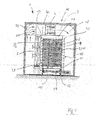
- FIG. 1 illustrates in simplified representation the structure of an inventively designed cooling tunnel in section.
- the product stack 11 is shown stacked on the pallet 30.
- the cooling tunnel consists of a plurality of successively arranged treatment stations 10 through which the loaded pallet can be transported on the transport device 16.
- the treatment stations 10 are bounded or closed at the top by a wall 34 formed of sheet material, for example, and have an inflow region 36 for gaseous treatment medium on one side and an outflow region 38 for the gaseous treatment medium on the other side.
- a wall 34 formed of sheet material, for example, and have an inflow region 36 for gaseous treatment medium on one side and an outflow region 38 for the gaseous treatment medium on the other side.
- an air cooler 6 may be provided when the gaseous treatment medium for cooling the products 2 cooling air is used.
- a plurality of nozzle plates 6 are provided with nozzles 7, through which, as indicated by arrows P1, the cooling air can flow laterally into the treatment chamber 28, there is a working flow 9, which may consist of individual turbulent and / or laminar flows ,
- a pressure measuring device 15 is provided at least one point in front of the nozzle plate 6
- the cooling air or the working flow 9 After the cooling air or the working flow 9 has flowed through the products to be treated, or has flowed along the products to be treated, it exits, as indicated by arrows P2, from the stack of products to be treated 2 and enters the outlet region 38 in the air cooler 40 or any other treatment arrangement for a gaseous treatment medium. Subsequent to the outflow region 38 or the air cooler 5, a flow channel region 44 is provided, in which the cooling air flows to a blower arrangement 4, which in turn is followed by a flow channel region 48, via which the cooling air conveyed through the blower arrangement 4 can then flow to the inflow region 36. The result is a circular circulation of the cooling air or the treatment medium.
- flow channel regions 44, 48 may be delimited, for example, by a wall arrangement 50 surrounding the entire tunable section 18.
- flow channels known per se in the area of air conditioning technology for example formed from sheet metal parts.
- a weight sensor 12 To determine the stack height is below the pallet 30, a weight sensor 12, by means of which the stack height can be determined.
- the nozzles 7 or nozzle groups 8 in the nozzle plate can be opened or closed as exemplified in FIG FIG. 2 shown.
- a movably arranged closure plate 14 is arranged in front of the nozzle group 8. With this exemplified closure plate, the upper nozzle group 8 can be closed.
- FIGS. 3 and 4 further embodiment of the nozzle plates 6 are shown. So is in FIG. 3 a nozzle plate shown with different nozzle openings.
- a primary air flow and a secondary air flow can be generated, which have different flow velocities.
- the primary air flow with a comparatively high flow rate embedded or trapped in a secondary air stream at a lower flow rate.
- the secondary air flow thus surrounds the primary air flow at a peripheral surface or outer surface enclosing the flow lines or flow direction of the primary air flow.
- the primary air flow 19 with the high flow velocity also carries with it the secondary air flow 20 and aligns it with according to the flow guidance of the primary air flow 19 with.
- a working flow 9 is generated, which improves the loading of the product stack, whereby a more uniform cooling of the products can be achieved.
- nozzle openings and / or shapes are achieved by means of different sized nozzle openings and / or shapes.
- a variant of a nozzle plate is shown, which consists of a cavity 21 having a nozzle plate with a front and a back.
- the primary air flow 19 is generated in that the treatment medium 3 is directed from the back by relatively large nozzles which pass through the cavity of the nozzle plate 6 to the front.
- the secondary flow 20, is generated by the treatment medium flowing into the cavity 21 of the nozzle plate and exiting from there through relatively small nozzles on the front side.
- FIG. 4 a nozzle plate is shown with adjustable nozzles, so that the flow guide can be selected individually depending on the product stacks and the packages.
Abstract
Description
Die Erfindung bezieht sich auf eine Behandlungsvorrichtung und ein Verfahren zum Kühlen von Erzeugnissen mit einem gasförmigen Behandlungsmedium, vorzugsweise Luft, mit einer Gebläseanordnung zur Erzeugung einer Strömung des Behandlungsmediums, mindestens einer Kühlvorrichtung, mindestens einer Düsenplatte mit einer Vielzahl von Öffnungen in Form von Düsen oder Düsengruppen, zur Erzeugung einzelner Arbeitsströmungen des Behandlungsmediums und mindestens einem der Düsenplatte vorgelagerten Behandlungsplatz, für die zu behandelnden Erzeugnisstapel, die durch die Düsen oder Düsengruppen der Düsenplatte mit dem Behandlungsmedium beaufschlagbar sind.The invention relates to a treatment device and a method for cooling products with a gaseous treatment medium, preferably air, with a blower arrangement for generating a flow of the treatment medium, at least one cooling device, at least one nozzle plate having a plurality of openings in the form of nozzles or nozzle groups , For generating individual working flows of the treatment medium and at least one of the nozzle plate upstream treatment station, for the product stack to be treated, which can be acted upon by the nozzle or nozzle groups of the nozzle plate with the treatment medium.
Derartige Behandlungsvorrichtungen werden beispielsweise dazu eingesetzt, Lebensmittelerzeugnisse, z. B. Milcherzeugnisse, nach dem Fertigungsprozess abzukühlen. Während die Erzeugnisse die Behandlungsvorrichtung durchlaufen, werden diese mit definierten klimatischen Verhältnissen behandelt, beispielsweise durch Umströmen mit kühler Luft, um diese auf eine vorgegebene, auch zur nachfolgenden Lagerung geeignete Temperatur, zu kühlen.Such treatment devices are used, for example, food products, eg. B. Milk products to cool after the manufacturing process. While the products pass through the treatment device, they are treated with defined climatic conditions, for example by flowing around with cool air to cool them to a predetermined, suitable for subsequent storage temperature.
Die zu behandelnden Erzeugnisse werden dabei auf Paletten zu Erzeugnisstapel gestapelt und in die Behandlungsvorrichtung eingefahren, so dass eine große Anzahl derartiger Erzeugnisse gleichzeitig behandelt werden kann.The products to be treated are stacked on pallets to product stack and retracted into the treatment device, so that a large number of such products can be treated simultaneously.
Eine derartige Behandlungsvorrichtung oder auch Kühltunnel ist aus der
Neben den kontinuierlich betriebenen Kühltunneln, wie in der
Bei beiden Systemen besteht die Düsenplatte aus einer Vielzahl separater Einströmdüsen durch die erreicht wird, dass über den Einströmbereich hinweg eine Vielzahl an definierten Einströmstellen gebildet wird, in welchen das gasförmige Behandlungsmedium zum einen mit definierter Richtung und zum anderen mit definierter Geschwindigkeit einströmt. Die Einströmgeschwindigkeit, die das gasförmige Behandlungsmedium im Austrittsbereich der Einströmdüsen aufweist, liegt vorzugsweise im Bereich von 20-25 m/s. Eine derartig hohe Einströmgeschwindigkeit stellt sicher, dass, auch bedingt durch die relativ stark gebündelten Strahlen von einströmendem gasförmigem Behandlungsmedium, auch kleinste Ritzen zwischen den einzelnen zu behandelnden Erzeugnissen beziehungsweise kleinste Öffnungen in diese Erzeugnisse enthaltenden Verpackungsmaterialien, beispielsweise Kartons, durchströmt werden. Das Behandlungsmedium gelangt somit auch im inneren Volumenbereich der auf den Paletten gestapelten Erzeugnisse an diese Erzeugnisse heran und kann zu deren Behandlung, beispielsweise deren Kühlung, beitragen.In both systems, the nozzle plate consists of a plurality of separate inlet nozzles through which a plurality of defined inflow points is formed over the inflow region, into which the gaseous treatment medium flows on the one hand with a defined direction and on the other with a defined speed. The inflow velocity, which has the gaseous treatment medium in the outlet region of the inlet nozzles, is preferably in the range of 20-25 m / s. Such a high inflow velocity ensures that, also due to the relatively concentrated beams of incoming gaseous treatment medium, even the smallest gaps between the individual products to be treated or smallest openings in packaging materials containing these products, for example cardboard, are flowed through. The treatment medium thus also approaches these products in the inner volume range of the products stacked on the pallets and can contribute to their treatment, for example their cooling.
Nachteilig bei dieser Art von Kühltunneln und Düsenplatte ist, dass keine Anpassung an die Palettenbeladung erfolgt und so der Energiebedarf für die Druckversorgungseinrichtung zur Erzeugung der erforderlichen Strömungsgeschwindigkeit bei nicht voll beladenen Paletten annähernd genauso hoch ist wie bei voll beladenen Paletten.A disadvantage of this type of cooling tunnels and nozzle plate is that no adaptation to the pallet loading takes place and so the energy requirements for the pressure supply device for generating the required flow rate at not fully loaded pallets is almost as high as in fully loaded pallets.
Der Erfindung liegt daher die Aufgabe zugrunde, eine Behandlungsvorrichtung mit einer höheren Energieeffizienz zu schaffen, die eine Anpassung an die Palettenbeladung ermöglicht.The invention is therefore based on the object to provide a treatment device with a higher energy efficiency, which allows adaptation to the pallet load.
Erfindungsgemäß wird die Aufgabe durch eine Behandlungsvorrichtung mit den Merkmalen des Anspruchs 1 und einem Verfahren nach Anspruch 11 gelöst. Vorteilhafte Ausgestaltungen sind in den Unteransprüchen beschrieben.According to the invention the object is achieved by a treatment device having the features of
Erfindungsgemäß wird eine Behandlungsvorrichtung zum Kühlen von Erzeugnissen mit einem gasförmigen Behandlungsmedium vorgeschlagen. Vorzugsweise ist das Behandlungsmedium Umgebungsluft, welche mittels einer Gebläseanordnung, zur Erzeugung einer Strömung des Behandlungsmediums, in der Behandlungsvorrichtung eine kreisförmige Basisströmung erzeugt. Die kreisförmige Basisströmung strömt dabei durch mindestens eine Kühlvorrichtung, mindestens einer Düsenplatte mit einer Vielzahl von Öffnungen in Form von Düsen oder Düsengruppen, zur Erzeugung einzelner Arbeitsströmungen des Behandlungsmediums und mindestens einem der Düsenplatte vorgelagerten Behandlungsplatz, für die zu behandelnden Erzeugnisstapel, die durch die Düsen oder Düsengruppen der Düsenplatte mit dem Behandlungsmedium beaufschlagbar sind. Zur Druckregelung des Behandlungsmediumstaudrucks vor den Düsenöffnungen ist zusätzlich eine Druckregelung vorhanden.According to the invention, a treatment device for cooling products with a gaseous treatment medium is proposed. The treatment medium is preferably ambient air, which generates a circular base flow in the treatment device by means of a blower arrangement for generating a flow of the treatment medium. The circular base flow in this case flows through at least one cooling device, at least one nozzle plate having a plurality of openings in the form of nozzles or nozzle groups, for generating individual working flows of the treatment medium and at least one treatment station upstream of the nozzle plate, for the product stacks to be treated through the nozzles or Nozzle groups of the nozzle plate can be acted upon with the treatment medium. For pressure control of the Behandlungsmediumstaudrucks before the nozzle openings, a pressure control is also available.
Durch die Druckregelung wird in Vorteilhafterweise bewirkt, dass eine konstante Arbeitsströmung im Austrittsbereich der Düsen oder Düsengruppen erzeugt wird und an den Strömungswiderstand durch die Düsenplatte und den Erzeugnisstapel angepasst werden kann. Wird ein geringerer Staudruck benötigt, kann die Drehzahl der Ventilatoren und so der Energieverbrauch gesenkt werden.By the pressure control is effected in an advantageous manner that a constant working flow in the outlet region of the nozzle or nozzle groups is generated and can be adapted to the flow resistance through the nozzle plate and the product stack. If a lower dynamic pressure is required, the speed of the fans and thus the energy consumption can be reduced.
Zusätzlich zum Drucksensor wird erfindungsgemäß vorgeschlagen eine Gewichtssensor oder alternativ einen optischen Sensor am Behandlungsplatz vorzusehen, so kann aus dem Gewicht oder die optischen Messung die Höhe des Erzeugnisstapels ermittelt werden.In addition to the pressure sensor, it is proposed according to the invention to provide a weight sensor or alternatively an optical sensor at the treatment station, so that the height of the product stack can be determined from the weight or the optical measurement.
Zum Kühlen der Erzeugnisstapel ist es im Wesentlichen notwendig, dass die Düsen aktiv sind, die eine Arbeitsströmung erzeugen, die den Erzeugnisstapel treffen. Alle Düsen deren Arbeitsströmungen am Erzeugnisstapel vorbeiführen haben keinen oder einen vernachlässigbaren Einfluss auf die Kühlung der Erzeugnisse und werden erfindungsgemäß verschlossen.For cooling the product stacks, it is essentially necessary for the nozzles to be active, generating a working flow that hits the product stack. All nozzles whose working flows pass the product stack have no or negligible influence on the cooling of the products and are sealed according to the invention.
Zum Verschließen einzelner Düsen oder Düsengruppen auf der Düsenplatte sind Mittel vorhanden, wie beispielweise verschiebbare Verschlussbleche. Damit sind die Düsen oder Düsengruppen in der Weise verschließbar, dass nur die Düsen oder Düsengruppen geöffnet sind, deren Arbeitsströmungen auf den Erzeugnisstapel treffen.For closing individual nozzles or nozzle groups on the nozzle plate means are present, such as sliding closure plates. Thus, the nozzles or nozzle groups are closable in such a way that only the nozzles or nozzle groups are open, meet the working currents on the product stack.
Der Verschluss der Düsen erfolgt erfindungsgemäß aufgrund der ermittelten Stapelhöhe. Je mehr Düsen verschlossen sind, desto geringer kann die Ventilatordrehzahl gewählt werden um den benötigten Staudruck zu erzeugen und somit verringert sich auch die Energieaufnahme der Ventilatoren.The closure of the nozzles takes place according to the invention on the basis of the determined stack height. The more nozzles are closed, the lower the fan speed can be selected to generate the required back pressure and thus also reduces the energy consumption of the fans.
Zudem wird vorgeschlagen in der Düsenplatte Düsenöffnungen anzuordnen die eine turbulente Strömung und /oder eine laminare Strömung erzeugen. Vorzugsweise ist die Düsenplatte so gestaltet, dass eine Arbeitsströmung des Behandlungsmediums entsteht, bei der turbulente Strömungen durch laminare Strömungen gestützt werden. Durch diese Anordnung wird eine verbesserte Durchströmung der Erzeugnisstapel und eine Vergleichmäßigung der Kühlung erreicht.In addition, it is proposed to arrange nozzle openings in the nozzle plate which generate a turbulent flow and / or a laminar flow. Preferably, the nozzle plate is designed so that a working flow of the treatment medium is formed in which turbulent flows are supported by laminar flows. By this arrangement, an improved flow through the product stack and a homogenization of the cooling is achieved.
Erfindungsgemäß wird eine weitere Ausführung der Düsenplatte vorgeschlagen die unterschiedliche Düsenöffnungen aufweist, durch die die Arbeitsströmung in einen Primärluftstrom und einen Sekundärluftstrom geteilt wird. Die Aufteilung erfolgt so, dass eine Arbeitsströmung des Behandlungsmediums mit einem Primärluftstrom (19) und einem Sekundärluftstrom (20) entsteht, wobei diese unterschiedliche Strömungsgeschwindigkeiten aufweisen.According to the invention, a further embodiment of the nozzle plate is proposed which has different nozzle openings, through which the working flow is divided into a primary air flow and a secondary air flow. The division takes place so that a working flow of the treatment medium with a primary air flow (19) and a secondary air flow (20) is formed, these having different flow velocities.
Besonders Vorteilhaft ist es, wenn die unterschiedlichen Düsenöffnungen zu Erzeugung der unterschiedlichen Luftströme so angeordnet sind, dass der Sekundärluftstrom den Primärluftstrom im Wesentlichen vollständig umgibt und der Primärluftstrom eine im Mittel höhere Strömungsgeschwindigkeit aufweißt als der Sekundärluftstrom.It is particularly advantageous if the different nozzle openings for generating the different air flows are arranged so that the secondary air flow substantially completely surrounds the primary air flow and the Primary air flow has a mean higher flow rate than the secondary air flow.
Die unterschiedlichen Strömungen könne z.B. durch unterschiedliche Düsengrößen und/oder Düsenformen erzielt werden. Dabei ist die Primärströmung als turbulente Strömung und die Sekundärströmung als laminare Strömung auszulegen.The different flows could e.g. can be achieved by different nozzle sizes and / or nozzle shapes. The primary flow should be interpreted as a turbulent flow and the secondary flow as a laminar flow.
Die Arbeitsströmung verlässt die Düsen, die Düsengruppen oder die Primärdüsenöffnung der Düsenplatte mit einer Strömungsgeschwindigkeit im Bereich von 15-30 m/s, vorzugsweise mit 20-25 m/s.The working flow leaves the nozzles, the nozzle groups or the primary nozzle orifice of the nozzle plate at a flow rate in the range of 15-30 m / s, preferably 20-25 m / s.
Die Sekundärströmung verlässt die Düsen mit einer Strömungsgeschwindigkeit im Bereich von 0,1-5m/s.The secondary flow leaves the nozzles at a flow rate in the range of 0.1-5m / s.
Alternativ wird vorgeschlagen die Düsen oder Düsengruppen auf der Düsenplatte verstellbar auszuführen, so dass die Arbeitsströmungen der einzelnen Düsen der Düsenplatte auf den Erzeugnisstapel lenkbar sind. So kann in Vorteilhafterweise erreicht werden, dass die gesamte Arbeitsströmung durch den Erzeugnisstapel strömt und einzelne Arbeitströmungen auf kritische Stellen des Erzeugnisstapels gelenkt werden können.Alternatively, it is proposed to make the nozzles or nozzle groups adjustable on the nozzle plate, so that the working flows of the individual nozzles of the nozzle plate can be steered onto the product stack. Thus, it can advantageously be achieved that the entire working flow flows through the product stack and individual working flows can be directed to critical points of the product stack.
Zudem wird ein Verfahren zum Kühlen von Erzeugnissen mit einem gasförmigen Behandlungsmedium, in einer entsprechenden Behandlungsvorrichtung vorgeschlagen bei der der Behandlungsmediumstaudruck vor den Düsenöffnungen, geregelt wird, vorzugsweise über die Drehzahl der Gebläse.In addition, a method for cooling products with a gaseous treatment medium, in a corresponding treatment device is proposed in which the Behandlungsmediumstaudruck is controlled before the nozzle openings, preferably on the speed of the fan.
Weiterhin wird vorgeschlagen mit Hilfe eines Gewichtssensors am Behandlungsplatz oder eines optischen Sensors die Höhe des Erzeugnisstapels zu ermittelt und anschließend die Düsen oder Düsengruppen zu verschließen, deren Arbeitsströmungen nicht auf den Erzeugnisstapel treffen.Furthermore, it is proposed with the aid of a weight sensor at the treatment station or an optical sensor to determine the height of the product stack and then to close the nozzles or nozzle groups whose working flows do not hit the product stack.
Die erfindungsgemäße Lösung wird nachfolgend anhand von Figuren erläutert. Darin ist im Einzelnen folgendes dargestellt:
Figur 1- zeigt ein erfindungsgemäßer Kühltunnel in Schnittdarstellung
Figur 2- zeigt eine Düsenplatte mit Verschlussmechanismus und Düsen- anordnung in zwei Ansichten
Figur 3- zeigt eine Ausführungsform der Düsenplatte mit unterschiedlichen Düsenöffnungen
- Figur 4
- zeigt beispielhaft eine bewegliche Düse
- FIG. 1
- shows a cooling tunnel according to the invention in a sectional view
- FIG. 2
- shows a nozzle plate with closure mechanism and nozzle arrangement in two views
- FIG. 3
- shows an embodiment of the nozzle plate with different nozzle openings
- FIG. 4
- shows an example of a movable nozzle
Die
Die Behandlungsplätze 10 sind nach oben hin durch eine beispielsweise aus Blechmaterial gebildete Wandung 34 begrenzt beziehungsweise abgeschlossen und weisen an einer Seite einen Einströmbereich 36 für gasförmiges Behandlungsmedium und an der anderen Seite einen Ausströmbereich 38 für das gasförmige Behandlungsmedium auf. Beispielsweise kann im Ausströmbereich 38 ein Luftkühler 6 vorgesehen sein, wenn das gasförmige Behandlungsmedium zum Kühlen der Erzeugnisse 2 Kühlluft verwendet wird.The treatment stations 10 are bounded or closed at the top by a
Im Einströmbereich 36 ist eine Mehrzahl von Düsenplatten 6 mit Düsen 7 vorgesehen, durch welche, wie durch Pfeile P1 angedeutet, die Kühlluft seitlich in den Behandlungsraum 28 einströmen kann, es entsteht eine Arbeitsströmung 9, die aus einzelnen turbulenten und/oder laminaren Strömungen bestehen kann.In the
Zur Messung des Staudrucks ist eine Druckmessvorrichtung 15 an mindestens einer Stelle vor der Düsenplatte 6 vorgesehenFor measuring the dynamic pressure, a pressure measuring device 15 is provided at least one point in front of the
Nachdem die Kühlluft bzw. die Arbeitsströmung 9 die zu behandelnden Erzeugnisse durchströmt hat, beziehungsweise entlang der zu behandelnden Erzeugnisse geströmt ist, tritt sie, wie durch Pfeile P2 angedeutet, aus dem Stapel der zu behandelnden Erzeugnisse 2 aus und tritt im Austrittsbereich 38 in den Luftkühler 40 oder einer sonstigen Aufbereitungsanordnung für ein gasförmige Behandlungsmedium ein. Anschließend an den Ausströmbereich 38 beziehungsweise den Luftkühler 5 ist ein Strömungskanalbereich 44 vorgesehen, in welchem die Kühlluft zu einer Gebläseanordnung 4 strömt, auf welche wiederum ein Strömungskanalbereich 48 folgt, über den die durch die Gebläseanordnung 4 voran geförderte Kühlluft dann zum Einströmbereich 36 strömen kann. Es entsteht eine kreisförmige Zirkulation der Kühlluft bzw. des Behandlungsmediums.After the cooling air or the working flow 9 has flowed through the products to be treated, or has flowed along the products to be treated, it exits, as indicated by arrows P2, from the stack of products to be treated 2 and enters the
Es sei darauf hingewiesen, dass die Strömungskanalbereiche 44, 48 beispielsweise durch eine den gesamten Tunellabschnitt 18 umgebende Wandungsanordnung 50 begrenzt sein können. Hier können jedoch selbstverständlich auch im Bereich der Klimatisierungstechnik an sich bekannte, beispielsweise aus Blechteilen gebildete, Strömungskanäle eingesetzt werden.It should be pointed out that the
Zur Bestimmung der Stapelhöhe befindet sich unterhalb der Palette 30 ein Gewichtssensor 12, mit dessen Hilfe die Stapelhöhe ermittelt werden kann.To determine the stack height is below the pallet 30, a
Entsprechend der Stapelhöhe können die Düsen 7 oder Düsengruppen 8 in der Düsenplatte geöffnet oder geschlossen werden wie beispielhaft in
In den
Der Primärluftstrom 19 mit der hohen Strömungsgeschwindigkeit führt zudem den Sekundarluftstrom 20 mit sich mit und richtet diesen gemäß der Strömungsführung des Primärluftstromes 19 mit aus. Somit wird also eine Arbeitsströmung 9 erzeugt, die die Beaufschlagung des Erzeugnisstapels verbessert, wodurch sich eine gleichmäßigere Abkühlung der Erzeugnisse erreichen lässt.The
Die beiden Luftströmungen werden mittels unterschiedlich großen Düsenöffnungen und /oder Formen erreicht. In
Die Sekundärströmung 20 wird dagegen dadurch erzeugt, dass das Behandlungsmedium in den Hohlraum 21 der Düsenplatte einströmt und von da aus durch relativ kleine Düsen auf der Vorderseite austritt.The
In
- 11
- Behandlungsvorrichtungtreatment device
- 22
- Erzeugnissenproducts
- 33
- Behandlungsmediumtreatment medium
- 44
- Gebläseanordnungblower assembly
- 55
- Kühlvorrichtungcooler
- 66
- Düsenplattenozzle plate
- 77
- Düsenjet
- 88th
- Düsengruppennozzle groups
- 99
- Arbeitsströmungenwork flows
- 1010
- Behandlungsplatztreatment center
- 1111
- Erzeugnisstapelproduct stack
- 1212
- Gewichtssensorweight sensor
- 1313
- optischer Sensoroptical sensor
- 1414
- VerschlussblechSealing sheet
- 1515
- DruckmessvorrichtungPressure measuring device
- 1616
- Transportvorrichtungtransport device
- 17,1817.18
- verschiedene Düsenöffnungendifferent nozzle openings
- 1919
- Primärströmungprimary flow
- 2020
- Sekundärströmungsecondary flow
- 2121
- Hohlraumcavity
- 2222
- Rückseiteback
- 2323
- Vorderseitefront
- 2828
- Behandlungsraumtreatment room
- 3030
- Palettepalette
- 3434
- Wandungwall
- 3636
- Einströmbereichinflow
- 3838
- Ausströmbereichoutflow
- 44,4844.48
- StrömungskanalbereichFlow channel area
- 5050
- Wandungwall
Claims (13)
dadurch gekennzeichnet,
dass eine Druckregelung vorhanden ist, mit der der Behandlungsmediumstaudruck vor den Düsenöffnungen regelbar ist.Treatment device (1) for cooling products (2) with a gaseous treatment medium (3), preferably air, with a blower arrangement (4) for generating a flow of the treatment medium, at least one cooling device (5), at least one nozzle plate (6) with one Variety of openings in the form of nozzles (7) or nozzle groups (8), for generating individual working flows (9) of the treatment medium (3) and at least one of the nozzle plate (6) upstream treatment station (10) for the product stack to be treated (11) , which can be acted upon by the nozzles (7) or nozzle groups (8) of the nozzle plate (6) with the treatment medium (3)
characterized,
that a pressure control is provided, with which the Behandlungsmediumstaudruck is adjustable in front of the nozzle openings.
dadurch gekennzeichnet,
dass am vorgelagerten Behandlungsplatz (10) eine Gewichtssensor (12) vorhanden ist, mit dessen Hilfe das Gewicht des Erzeugnisstapels ermittelbar ist und daraus die Höhe des Erzeugnisstapels (11) bestimmt werden kann.Treatment device according to claim 1,
characterized,
that a weight sensor (12) is provided at the upstream treatment station (10), with the aid of which the weight of the product stack can be determined and from this the height of the product stack (11) can be determined.
dadurch gekennzeichnet,
dass am vorgelagerten Behandlungsplatz ein optischer Sensor (13) vorhanden ist, mit dessen Hilfe die Höhe des Erzeugnisstapels (11) ermittelt werden kann.Treatment device according to claim 1,
characterized,
that at the upstream treatment station is an optical sensor (13) is present, by means of which the height of the product stack (11) can be determined.
dadurch gekennzeichnet,
dass Mittel (14) zum Verschließen einzelner Düsen (7) oder Düsengruppen (8) auf der Düsenplatte (6) vorhanden sind.Treatment device according to one of claims 1 to 3,
characterized,
in that means (14) for closing individual nozzles (7) or nozzle groups (8) on the nozzle plate (6) are present.
dadurch gekennzeichnet,
dass die Düsen (7) oder Düsengruppen (8) in der Weise verschließbar sind, dass nur die Düsen (7) oder Düsengruppen (8) geöffnet sind, deren Arbeitsströmungen (9) auf den Erzeugnisstapel (11) treffen.Treatment device according to claim 4,
characterized,
in that the nozzles (7) or nozzle groups (8) can be closed in such a way that only the nozzles (7) or nozzle groups (8) are opened whose working flows (9) hit the product stack (11).
dadurch gekennzeichnet,
dass die Düsenplatte (6) unterschiedliche Düsenöffnungen aufweist, durch die die Arbeitsströmung (9) in einen Primärluftstrom (19) und einen Sekundärluftstrom (20) geteilt wird, so dass eine Arbeitsströmung (9) des Behandlungsmediums mit einem Primärluftstrom (19) und einem Sekundärluftstrom (20) entsteht, die unterschiedliche Strömungsgeschwindigkeiten aufweisen.Treatment device according to one of the preceding claims,
characterized,
that the nozzle plate (6) has different nozzle openings through which the working fluid (9) into a primary air stream (19) and a secondary air stream (20) is divided, so that a working fluid (9) of the treatment medium, with a primary air flow (19) and a secondary air stream (20) arises, which have different flow velocities.
dadurch gekennzeichnet,
dass die unterschiedlichen Düsenöffnungen so angeordnet sind, dass der Sekundärluftstrom (20) den Primärluftstrom (19) im Wesentlichen vollständig umgibt und der Primärluftstrom (19) eine im Mittel höhere Strömungsgeschwindigkeit aufweißt als der Sekundärluftstrom (20).Treatment device according to claim 6,
characterized,
that the different nozzle openings are arranged so that the secondary air stream (20) surrounding the primary air stream (19) essentially completely and the primary air stream (19) has a higher mean flow velocity aufweißt as the secondary air stream (20).
dadurch gekennzeichnet,
dass die Arbeitsströmungen (9) die Düsen (7), die Düsengruppen (8) oder die Primärdüsenöffnung mit einer Strömungsgeschwindigkeit im Bereich von 15-30 m/s, vorzugsweise 20-25 m/s verlässt.Treatment device according to one of claims 1 to 7,
characterized,
that the work flows (9), the nozzles (7), the nozzle groups (8) or the primary orifice at a flow rate in the range of 15-30 m / s, preferably 20-25 m / s leaves.
dadurch gekennzeichnet,
dass die Düsen (7) oder Düsengruppen (8) auf der Düsenplatte verstellbar sindTreatment device according to one of the preceding claims,
characterized,
that the nozzles (7), or groups of nozzles (8) are adjustable in the nozzle plate
dadurch gekennzeichnet,
dass der Behandlungsmediumstaudruck vor den Düsenöffnungen, geregelt wird.Method for cooling products (2) with a gaseous treatment medium (3), preferably air, with a blower arrangement (4) for generating a flow of the treatment medium, at least one cooling device (5), at least one nozzle plate (6) with a multiplicity of openings in the form of nozzles (7) or nozzle groups (8), for generating individual working flows (9) of the treatment medium (3) and at least one of the nozzle plate (6) upstream treatment station (10), for the product stack (11) to be treated by the nozzles (7) or nozzle groups (8) of the nozzle plate (6) can be acted upon by the treatment medium (3)
characterized,
that the Behandlungsmediumstaudruck before the nozzle openings, is regulated.
dadurch gekennzeichnet,
dass der Behandlungsmediumstaudruck vor den Düsenöffnungen über die Drehzahl der Gebläseanordnung geregelt wird.Method according to claim 10
characterized,
that the Behandlungsmediumstaudruck is controlled in front of the nozzle openings on the speed of the fan assembly.
dadurch gekennzeichnet,
dass am vorgelagerten Behandlungsplatz mit Hilfe eines Gewichtssensors die Höhe des Erzeugnisstapels ermittelt wird.Method according to claim 10
characterized,
that the height of the product stack is determined at the upstream treatment station with the aid of a weight sensor.
dadurch gekennzeichnet,
dass die Düsen oder Düsengruppen verschlossen werden deren Arbeitsströmungen nicht auf den Erzeugnisstapel treffen.Method according to claim 10
characterized,
that the nozzles or nozzle groups are closed whose working flows do not hit the product stack.
Applications Claiming Priority (1)
| Application Number | Priority Date | Filing Date | Title |
|---|---|---|---|
| DE200910045211 DE102009045211A1 (en) | 2009-09-30 | 2009-09-30 | Device and method for cooling products |
Publications (1)
| Publication Number | Publication Date |
|---|---|
| EP2309216A2 true EP2309216A2 (en) | 2011-04-13 |
Family
ID=43305052
Family Applications (1)
| Application Number | Title | Priority Date | Filing Date |
|---|---|---|---|
| EP20100170553 Withdrawn EP2309216A2 (en) | 2009-09-30 | 2010-07-23 | Device and method for cooling products |
Country Status (2)
| Country | Link |
|---|---|
| EP (1) | EP2309216A2 (en) |
| DE (1) | DE102009045211A1 (en) |
Citations (2)
| Publication number | Priority date | Publication date | Assignee | Title |
|---|---|---|---|---|
| DE10017408A1 (en) | 2000-04-07 | 2001-10-11 | Wiessner Gmbh | Tunnel for treating, in particular, for cooling food products by means of a cooling medium, preferably air comprises inflow zone which is provided with air inlet nozzles |
| EP1455151A1 (en) | 2003-03-07 | 2004-09-08 | M+W Zander Facility Engineering GmbH | Method for cooling products, in particular food, especially dairy products, and device for carrying out the method |
-
2009
- 2009-09-30 DE DE200910045211 patent/DE102009045211A1/en not_active Withdrawn
-
2010
- 2010-07-23 EP EP20100170553 patent/EP2309216A2/en not_active Withdrawn
Patent Citations (2)
| Publication number | Priority date | Publication date | Assignee | Title |
|---|---|---|---|---|
| DE10017408A1 (en) | 2000-04-07 | 2001-10-11 | Wiessner Gmbh | Tunnel for treating, in particular, for cooling food products by means of a cooling medium, preferably air comprises inflow zone which is provided with air inlet nozzles |
| EP1455151A1 (en) | 2003-03-07 | 2004-09-08 | M+W Zander Facility Engineering GmbH | Method for cooling products, in particular food, especially dairy products, and device for carrying out the method |
Also Published As
| Publication number | Publication date |
|---|---|
| DE102009045211A1 (en) | 2011-03-31 |
Similar Documents
| Publication | Publication Date | Title |
|---|---|---|
| EP0541630B1 (en) | Device for cooling extruded profiles | |
| EP2049401B1 (en) | Method of shrinking a shrink-fit film onto packs, and apparatus for implementing the method | |
| EP2554483B1 (en) | Shrink tunnel | |
| WO2018041781A1 (en) | Oxidation furnace | |
| DE102012103398A1 (en) | Shrinking device for heat shrinking of film around article or article combination, has movable cover bar assigned to nozzle area of shaft wall with certain length, where length of cover bar corresponds to former length | |
| EP3672893B1 (en) | Diverting apparatus with coanda stabilizing device | |
| DE102007059654A1 (en) | Processing device for cooling/heating object in e.g. automatic warehouse, has nozzle openings with cross-section varying over extension area of openings such that concentration area is formed for supplying increased volume of medium | |
| WO1997005437A1 (en) | Process and device for drying ceramic green bricks | |
| EP0945695A1 (en) | Apparatus for treating web material | |
| EP2309216A2 (en) | Device and method for cooling products | |
| EP2771630B1 (en) | Cooling device | |
| EP2551207A1 (en) | Shrink device with container cooling | |
| DE4116019C2 (en) | Method and device for cooling a flat material, in particular a metal strip | |
| EP0283869A2 (en) | Device to expose to a gas stream objects with flat surfaces in a position which can be traversed | |
| DE102021103837A1 (en) | Shrinkage device and method for optimizing the energy output of a shrinkage device | |
| EP2586717B1 (en) | Shrink tunnel | |
| DE102013101477A1 (en) | SHRINKING DEVICE | |
| DE1954097A1 (en) | Method and device for cooling or heating food in portion containers | |
| DE102011080807A1 (en) | Nozzle wall element for a cooling tunnel | |
| EP0174589A1 (en) | Apparatus for heating or cooling metal products | |
| DE1900287A1 (en) | Thermal treatment of paper and metal strips and - painted metal | |
| EP4043354A1 (en) | Shrinking device, method of optimizing the shrinking of packaging material onto an assembly comprising at least one item and shrink module | |
| DE2103674C3 (en) | Method and device for cooling hot bulk materials in open coolers | |
| DE102009045152A1 (en) | Product e.g. yoghurt, cooling method for food industry, involves supplying cooling agent streams to appropriate stack of product from opposite directions and transverse to conveying direction of stack through cooling tunnel | |
| EP4067247A1 (en) | Shrinking device and method for transferring a shrinking device to a standby mode |
Legal Events
| Date | Code | Title | Description |
|---|---|---|---|
| PUAI | Public reference made under article 153(3) epc to a published international application that has entered the european phase |
Free format text: ORIGINAL CODE: 0009012 |
|
| AK | Designated contracting states |
Kind code of ref document: A2 Designated state(s): AL AT BE BG CH CY CZ DE DK EE ES FI FR GB GR HR HU IE IS IT LI LT LU LV MC MK MT NL NO PL PT RO SE SI SK SM TR |
|
| AX | Request for extension of the european patent |
Extension state: BA ME RS |
|
| STAA | Information on the status of an ep patent application or granted ep patent |
Free format text: STATUS: THE APPLICATION IS DEEMED TO BE WITHDRAWN |
|
| 18D | Application deemed to be withdrawn |
Effective date: 20130201 |