EP2309109B1 - Gas turbine and method of operating gas turbine - Google Patents
Gas turbine and method of operating gas turbine Download PDFInfo
- Publication number
- EP2309109B1 EP2309109B1 EP09773233.3A EP09773233A EP2309109B1 EP 2309109 B1 EP2309109 B1 EP 2309109B1 EP 09773233 A EP09773233 A EP 09773233A EP 2309109 B1 EP2309109 B1 EP 2309109B1
- Authority
- EP
- European Patent Office
- Prior art keywords
- air
- gas turbine
- passages
- cooling
- passage
- Prior art date
- Legal status (The legal status is an assumption and is not a legal conclusion. Google has not performed a legal analysis and makes no representation as to the accuracy of the status listed.)
- Active
Links
- 238000000034 method Methods 0.000 title claims description 5
- 238000001816 cooling Methods 0.000 claims description 171
- 230000001105 regulatory effect Effects 0.000 claims description 4
- 238000011144 upstream manufacturing Methods 0.000 claims description 4
- 239000007789 gas Substances 0.000 description 104
- 239000000567 combustion gas Substances 0.000 description 18
- 238000005086 pumping Methods 0.000 description 11
- 239000000446 fuel Substances 0.000 description 8
- 238000000605 extraction Methods 0.000 description 7
- 230000007704 transition Effects 0.000 description 7
- 238000002485 combustion reaction Methods 0.000 description 6
- 230000000694 effects Effects 0.000 description 6
- 238000005516 engineering process Methods 0.000 description 6
- 239000002826 coolant Substances 0.000 description 5
- 238000011084 recovery Methods 0.000 description 4
- 239000012530 fluid Substances 0.000 description 3
- 239000000284 extract Substances 0.000 description 2
- 238000012986 modification Methods 0.000 description 2
- 230000004048 modification Effects 0.000 description 2
- 230000003068 static effect Effects 0.000 description 2
- 239000000470 constituent Substances 0.000 description 1
- 239000000498 cooling water Substances 0.000 description 1
- 230000006866 deterioration Effects 0.000 description 1
- -1 for example Substances 0.000 description 1
- 238000011017 operating method Methods 0.000 description 1
- 230000000284 resting effect Effects 0.000 description 1
Images


Classifications
-
- F—MECHANICAL ENGINEERING; LIGHTING; HEATING; WEAPONS; BLASTING
- F01—MACHINES OR ENGINES IN GENERAL; ENGINE PLANTS IN GENERAL; STEAM ENGINES
- F01D—NON-POSITIVE DISPLACEMENT MACHINES OR ENGINES, e.g. STEAM TURBINES
- F01D5/00—Blades; Blade-carrying members; Heating, heat-insulating, cooling or antivibration means on the blades or the members
- F01D5/02—Blade-carrying members, e.g. rotors
- F01D5/08—Heating, heat-insulating or cooling means
-
- F—MECHANICAL ENGINEERING; LIGHTING; HEATING; WEAPONS; BLASTING
- F02—COMBUSTION ENGINES; HOT-GAS OR COMBUSTION-PRODUCT ENGINE PLANTS
- F02C—GAS-TURBINE PLANTS; AIR INTAKES FOR JET-PROPULSION PLANTS; CONTROLLING FUEL SUPPLY IN AIR-BREATHING JET-PROPULSION PLANTS
- F02C7/00—Features, components parts, details or accessories, not provided for in, or of interest apart form groups F02C1/00 - F02C6/00; Air intakes for jet-propulsion plants
- F02C7/12—Cooling of plants
- F02C7/14—Cooling of plants of fluids in the plant, e.g. lubricant or fuel
- F02C7/141—Cooling of plants of fluids in the plant, e.g. lubricant or fuel of working fluid
-
- F—MECHANICAL ENGINEERING; LIGHTING; HEATING; WEAPONS; BLASTING
- F01—MACHINES OR ENGINES IN GENERAL; ENGINE PLANTS IN GENERAL; STEAM ENGINES
- F01D—NON-POSITIVE DISPLACEMENT MACHINES OR ENGINES, e.g. STEAM TURBINES
- F01D5/00—Blades; Blade-carrying members; Heating, heat-insulating, cooling or antivibration means on the blades or the members
- F01D5/02—Blade-carrying members, e.g. rotors
- F01D5/08—Heating, heat-insulating or cooling means
- F01D5/085—Heating, heat-insulating or cooling means cooling fluid circulating inside the rotor
- F01D5/087—Heating, heat-insulating or cooling means cooling fluid circulating inside the rotor in the radial passages of the rotor disc
-
- F—MECHANICAL ENGINEERING; LIGHTING; HEATING; WEAPONS; BLASTING
- F01—MACHINES OR ENGINES IN GENERAL; ENGINE PLANTS IN GENERAL; STEAM ENGINES
- F01D—NON-POSITIVE DISPLACEMENT MACHINES OR ENGINES, e.g. STEAM TURBINES
- F01D5/00—Blades; Blade-carrying members; Heating, heat-insulating, cooling or antivibration means on the blades or the members
- F01D5/12—Blades
- F01D5/14—Form or construction
- F01D5/18—Hollow blades, i.e. blades with cooling or heating channels or cavities; Heating, heat-insulating or cooling means on blades
-
- F—MECHANICAL ENGINEERING; LIGHTING; HEATING; WEAPONS; BLASTING
- F02—COMBUSTION ENGINES; HOT-GAS OR COMBUSTION-PRODUCT ENGINE PLANTS
- F02C—GAS-TURBINE PLANTS; AIR INTAKES FOR JET-PROPULSION PLANTS; CONTROLLING FUEL SUPPLY IN AIR-BREATHING JET-PROPULSION PLANTS
- F02C7/00—Features, components parts, details or accessories, not provided for in, or of interest apart form groups F02C1/00 - F02C6/00; Air intakes for jet-propulsion plants
- F02C7/12—Cooling of plants
- F02C7/16—Cooling of plants characterised by cooling medium
- F02C7/18—Cooling of plants characterised by cooling medium the medium being gaseous, e.g. air
-
- F—MECHANICAL ENGINEERING; LIGHTING; HEATING; WEAPONS; BLASTING
- F05—INDEXING SCHEMES RELATING TO ENGINES OR PUMPS IN VARIOUS SUBCLASSES OF CLASSES F01-F04
- F05D—INDEXING SCHEME FOR ASPECTS RELATING TO NON-POSITIVE-DISPLACEMENT MACHINES OR ENGINES, GAS-TURBINES OR JET-PROPULSION PLANTS
- F05D2240/00—Components
- F05D2240/10—Stators
- F05D2240/12—Fluid guiding means, e.g. vanes
-
- F—MECHANICAL ENGINEERING; LIGHTING; HEATING; WEAPONS; BLASTING
- F05—INDEXING SCHEMES RELATING TO ENGINES OR PUMPS IN VARIOUS SUBCLASSES OF CLASSES F01-F04
- F05D—INDEXING SCHEME FOR ASPECTS RELATING TO NON-POSITIVE-DISPLACEMENT MACHINES OR ENGINES, GAS-TURBINES OR JET-PROPULSION PLANTS
- F05D2240/00—Components
- F05D2240/60—Shafts
- F05D2240/61—Hollow
-
- F—MECHANICAL ENGINEERING; LIGHTING; HEATING; WEAPONS; BLASTING
- F05—INDEXING SCHEMES RELATING TO ENGINES OR PUMPS IN VARIOUS SUBCLASSES OF CLASSES F01-F04
- F05D—INDEXING SCHEME FOR ASPECTS RELATING TO NON-POSITIVE-DISPLACEMENT MACHINES OR ENGINES, GAS-TURBINES OR JET-PROPULSION PLANTS
- F05D2260/00—Function
- F05D2260/20—Heat transfer, e.g. cooling
Definitions
- the present invention relates to a gas turbine, and more particularly, to a gas turbine that cools a turbine blade.
- a gas turbine is an apparatus that extracts energy from combustion gas generated by combusting air and fuel therein.
- a gas turbine rotates a turbine by using energy of combustion gas generated by combusting fuel and compressed air, and outputs rotation energy from the rotor.
- the combustion gas is, however, supplied to the turbine while the combustion gas is hot. Therefore, the blade of the turbine is also exposed to hot atmosphere.
- a gas turbine is disclosed in which, air is supplied from a compressor, which is a supply source of cooling air, to a blade, which is a supply destination of cooling air, through a central hole or a hole provided along a central axis of a rotor thus the blade is, see e.g. EP1233147 .
- Patent Document 1 air compressed by the compressor via the central hole of the rotor flows from the compressor to the turbine via an internal passage, and is thus supplied to the blade as cooling air.
- Patent Document 1 some of air is extracted from a disk or a rotating member of the compressor to a cavity located in the compressor, and is supplied to the blade passage via the internal passage. Therefore, it is difficult to adjust amount of the extracted air while the gas turbine is in operation. Thus, during the maximum load operation, cooling air more than flow rate required for cooling the blade may be extracted from the compressor. As a result, a thermal efficiency of the gas turbine may be reduced.
- amount of cooling air necessary for cooling the blade differs in accordance with load of a gas turbine. More specifically, during high load operation, cooling capacity of a gas turbine needs to be increased by supplying high pressure air to a blade and thus securing necessary amount of air. During low load operation, amount of cooling air needs to be reduced. Therefore, deterioration of thermal efficiency of the gas turbine needs to be prevented by supplying comparatively low pressure air thereto and thus preventing consuming unnecessary air. In above Patent Documents, any means is not disclosed for adjusting amount of air in a gas turbine in which load thereof fluctuates.
- the present invention is made in view of the above, and it is an object of the present invention to provide a gas turbine which reduces a lowering of thermal efficiency.
- An operating method allows to select an air source of cooling air based on a load of gas turbine. Accordingly, proper air is used based on a load state, and a lowering of a total thermal efficiency of the gas turbine is prevented.
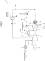
- Fig. 1 is an overall view of a gas turbine system according to a first embodiment of the present invention.
- Fig. 2 is a schematic for explaining a configuration of a gas turbine 3 according to the first embodiment.
- combustion air supplied to the gas turbine 3 according to the present embodiment is introduced to a compressor 20 via an air filter 71.
- the combustion air compressed by the compressor 20 at a predetermined pressure is supplied to a combustor 30, and in the combustor 30 the combustion air is mixed with fuel and is combusted.
- the combustion gas generated in the combustor 30 is introduced to a turbine 10.
- the combustion gas flows down a turbine vane 12 or a turbine blade 13
- heat energy is converted to rotation energy of a rotor 50 of the turbine 10
- the rotation energy is extracted as electric power from a generator 80.
- the gas turbine 3 includes the compressor 20, the combustor 30, the turbine 10, and an exhaust chamber 40, sequentially in the described order from upstream to downstream of flow of fluid as shown in Fig. 2 .
- the compressor 20 applies pressure to air and the pressed air is transmitted to the combustor 30.
- the combustor 30 supplies fuel to the air to ignite the air.
- the turbine 10 converts energy of the combustion gas sent out from the combustor 30 into rotation energy.
- the compressor 20 includes an air intake 21, a compressor housing 22, compressor vanes 23, compressor blades 24, and an bleed air manifold 25.
- the air intake 21 functions as an air inlet that delivers air introduced from the air filter 71 shown in Fig. 1 to the compressor housing 22.
- a plurality of compressor vanes 23 and a plurality of compressor blades 24 are alternately provided. Air compressed by the compressor 20 is brought to a chamber 36 in the combustor 30.
- the bleed air manifold 25 is provided outside the compressor vanes 23, and a function thereof is to temporarily accumulate compressed air extracted from an intermediate area of the compressor 20 for cooling the turbine vanes and turbine blades.
- the bleed air manifold 25 includes a compressor bleed air opening 26 that connects to external piping. A plurality of air extraction openings may be provided as the compressor bleed air openings 26.
- the compressor bleed air openings 26 may include a low pressure air extraction opening for low pressure air extracted from a low pressure intermediate area of the compressor and a high pressure air extraction opening for high pressure air extracted from a high pressure intermediate area of the compressor, and the low pressure air extraction opening or the high pressure air extraction opening may be used optionally according to operation status thereof.
- the combustor 30 includes a housing 31, a combustor liner 32, and a transition piece 33.
- the chamber 36 is formed.
- the combustor liner 32 is formed in a generally cylindrical shape and is provided in the chamber 36 as a passage for combustion gas.
- the transition piece 33 is provided as a passage for combustion gas.
- the transition piece 33 is formed in a generally cylindrical shape, and in the transition piece 33 a combustion zone 37 is formed in which air and fuel are combusted.
- the transition piece 33 is connected to one of the axial direction ends of the combustor liner 32.
- a fuel nozzle 34 that injects fuel into the inside of the combustor liner 32is provided.
- On the circumferential surface of the combustor liner 32 a plurality of combustor liner air intakes 35 are formed for introducing compressed air into the inside of the combustor liner 32.
- the turbine 10 includes a turbine casing 11, the turbine vanes 12, and the turbine blades 13. In the turbine casing 11, a plurality of turbine vanes 12 and a plurality of turbine blades 13 are alternately provided.
- the exhaust chamber 40 includes an exhaust diffuser 41 connected to the turbine 10. The exhaust diffuser 41 converts dynamic pressure of combustion gas having passed through the turbine 10, i.e., exhaust gas, to static pressure.
- the gas turbine 3 includes the rotor 50 as a rotating member.
- the rotor 50 is provided such that the rotor 50 penetrates the centers of the compressor 20, the combustor 30, the turbine 10, and the exhaust chamber 40.
- the rotor 50 is supported so that the end thereof on the side of the compressor 20 is rotatably supported by a bearing 51 and the end thereof on the side of the exhaust chamber 40 is rotatably supported by a bearing 52.
- a plurality of disks 14 are fixed on the rotor 50.
- the compressor blades 24 and the turbine blades 13 are connected to the disks 14.
- a drive shaft of a generator (not shown) is connected to one of the ends of the rotor 50 on the side of the compressor 20, a drive shaft of a generator (not shown) is connected. In the configuration, the gas turbine 3 drives the generator 80 to generate power.
- the gas turbine 3 supplies compressed air as cooling air in an intermediate area of the compressor 20 as a high pressure zone to a shaft directional passage 60.
- the gas turbine 3 includes a shaft end seal 67, an external passage 68, a cooler 69 as a cooling air cooling unit, and an air flow control valve 70.
- the shaft end seal 67 is mounted thereon such that the shaft end seal 67 covers a cooling air inlet 61 as well as communicates with the external passage 68.
- the cooling air inlet 61 and the external passage 68 communicate with each other via the shaft end seal 67 as shown in Fig. 4 .
- the external passage 68 is connected, for example, to the compressor bleed air openings 26 provided at the bleed air manifold 25 of the compressor 20.
- the cooler 69 is provided at the external passage 68. Now, a temperature of the compressed air extracted from the compressor 20 is higher than a temperature of the atmospheric air. Therefore, the cooler 69 cools cooling air flowing inside the external passage 68.
- the air flow control valve 70 is provided on the external passage 68, and regulates flow rate of cooling air flowing inside the external passage 68.
- a flow rate of the cooling air extracted from the compressor 20 and flowing inside the external passage 68 fluctuates according to operation status of the gas turbine 3. More specifically, the higher an operating load of the gas turbine is, the more cooling air flows inside the external passage 68.
- the cooling air extracted from the compressor 20 is supplied to the turbine 10 via the external passage 68. Then, a flow rate of the cooling air is regulated by the air flow control valve 70 and the cooling air is cooled by the cooler 69. The cooling air cooled by the cooler 69 is introduced to the cooling air inlet 61 via the external passage 68 and the shaft end seal 67.
- the combustion gas passing through a final area of the turbine is introduced from the exhaust chamber 40 to an exhaust heat recovering unit 42, and after heat recovery is performed, the combustion gas is emitted from a stack 43 to atmospheric air.
- the interiors of the turbine vanes 12 and the turbine blades 13 through which hot combustion gas flows are cooled by the cooling air, to avoid damage on blades that may be caused by the hot combustion gas.
- the cooling air cools the turbine vanes 12 and the turbine blades 13, and then is discharged to the combustion gas finally.
- combustion air compressed at the compressor 20 is extracted, as air supply of cooling air, from an intermediate area of the compressor 20, and is used as cooling air.
- a gas turbine that has a comparatively high thermal efficiency is needed. Therefore, hotter combustion gas is more likely used.
- necessity is increasing, compared with the conventional cooling, for cooling the turbine blades 13 in a posterior area of the turbine 10 located downstream along the flow of the combustion gas.
- Fig. 1 some of the extracted air in the compressor 20 is extracted, as air supply, from the compressor bleed air openings 26 to cool the turbine blades 13 in a posterior area of the turbine.
- the cooling air extracted from the compressor bleed air openings 26 flows through the external passage 68, and then is supplied to the turbine 10 from the side of the shaft end of the rotor 50 of the turbine 10.
- the air extracted from the compressor bleed air openings 26 is cooled at the cooler 69 at an appropriate temperature. Therefore, as a cooling medium, for example, cooling water is used. Comparatively low temperature fluid such as boiler working fluid in the exhaust heat recovering unit 42 in the gas turbine system can also be used as cooling medium of the cooler 69. Then, energy loss of the whole system is more reduced because heat recovery is thus performed. Regulation of a flow rate of the cooling air is performed by the air flow control valve 70, or an air flow rate adjusting unit, according to the load of the gas turbine. Adjustment of temperature of cooling air is performed by adjustment of cooling medium flow rate of the cooler 69 or by adjustment of amount of air of bypassing the cooler according to the load of the gas turbine.
- An air flow rate adjusting unit includes the air flow control valve 70 that can control air flow rate continuously as well as other units for adjusting flow rate of cooling air manually such as a hand valve and an orifice.
- the gas turbine system 1 includes the gas turbine 3 including the compressor 20, the turbine 10, the combustor 30, and the exhaust chamber 40 shown in Fig. 2 , the external passage 68 that provides cooling air disposed around the gas turbine 3 to the turbine, the cooler 69, and the air flow control valve 70.
- the gas turbine system 1 is configured such that the shaft end seal 67 and the external passage 68 can be removed or such that either one of atmospheric air or the compressor 20 can be selectively used as supply source of cooling air. Thus, air supply or supply source of cooling air can be switched according to operating status of the gas turbine 3.
- the gas turbine 3, as described above, has a function by which the turbine blades 13 can be cooled by the cooling air.
- the cooling air is used not only for cooling the turbine blades 13 but also the turbine vanes 12 and other components of the gas turbine. In the present embodiment, particularly the blades in a final area of the turbine blades 13 are cooled by the cooling air. Blades that are cooled, however, are not limited thereto.
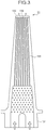
- Fig. 3 is a cross sectional view for schematically illustrating an example of a blade in a posterior area of the gas turbine according to the first embodiment.
- the turbine blades 13 includes a base 131, a tip section 132 that is a tip end of a turbine blade 13, and cooling passages 133 that are holes.
- the turbine blades 13 are mounted on the circumference of disk 14 shown in Fig. 2 by each base 131.
- the cooling passages 133 are formed such that the cooling passages 133 are air-hole spaces open into the base 131.
- a plurality of cooling passages 133 are formed generally linearly from the base 131 to the tip section 132.
- a plurality of cooling passages 133 are formed such that the cooling passages 133 are generally linear from the base 131 to the tip section 132.
- the present embodiment is not limited thereto. If the cooling passages 133 are provided in a plurality of the turbine blades 13 provided in the turbine 10 shown in Fig. 2 , the cooling passages 133 may be provided for example, in curved shape (as so-called serpentine passages).
- the cooling air flows into the cooling passages 133 from the base 131 side of the turbine blades 13, where the cooling air performs heat exchange between the wall surfaces inside the cooling passages 133. Then, the cooling air flows through the cooling passages 133 to the tip section 132 side of the turbine blades 13. The cooling air that thus flows through the cooling passages 133 performs heat exchange with the turbine blades 13 and cools the turbine blades 13.
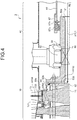
- Fig. 4 is a cross sectional view for schematically illustrating a passage in which cooling air flows.
- the gas turbine 3 according to the present embodiment includes the shaft directional passage 60, the cooling air inlet 61, a swirler 62 as swirl adding means, a first radial directional passage 63, a cavity 64, and a second radial directional passage 65.
- the shaft directional passage 60 is formed in cylindrical shape along a central axis RL of the rotor 50 on the side of the exhaust chamber 40.
- the shaft directional passage 60 is formed such that the central axis of the rotor is the same as the central axis of the shaft directional passage 60.
- One of the ends of the shaft directional passage 60 or the cooling air inlet 61 is communicated with the external passage 68 shown in Fig. 1 .
- the cooling air inlet 61 is formed, for example, at the end 50a of the rotor 50 on the side of the exhaust chamber 40 in a bell-mouth shape.
- Bell-mouth shape is a shape, in which the shape is tapered such that curvature thereof is generally bell-shaped, and a bore diameter of the cooling air inlet 61 is bigger upstream of flow of the cooling air and the bore diameter is smaller downstream of the flow.
- the cooling air inlet 61 can efficiently introduce the cooling air from the external passage 68 to the shaft directional passage 60.
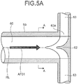
- Fig. 5A is a cross sectional view for schematically illustrating a swirler according to the first embodiment taken along a plane including the central axis thereof.
- Fig. 5B is a cross sectional view for schematically illustrating the swirler taken along a plane A-A in Fig. 5A .
- Fig. 5C is a cross sectional view for schematically illustrating the swirler taken along a plane B-B in Fig. 5B .
- the swirler 62 shown in Figs. 5A , 5B, and 5C is provided on one of the ends of the shaft directional passage 60 on the opposite side of the cooling air inlet 61 shown in Fig. 4 .
- the swirler 62 is a rotating member that rotates with the rotor 50 being fixed to the rotor 50.
- the swirler 62 includes a guide plate 62a.
- the guide plate 62a provides a swirl in the rotational direction of the rotor 50 to the cooling air inside the shaft directional passage 60 by rotation of the swirler 62.
- the cooling air is provided with velocity component in the rotational direction of the rotor 50 by the swirler 62, and thus flows.
- the swirler 62 may be provided at the cooling air inlet 61 or the other end of the shaft directional passage 60.
- the swirler 62 is preferably provided near the first radial directional passage 63.
- the shaft end seal 67 is provided that connects the shaft directional passage 60 that is driven rotationally and the external passage 68 that is a static structure such that the cooling air is introduced to the side of the turbine 10 without leakage of the cooling air.
- the shaft end seal 67 is a tight seal between a rotating body and a resting body having a seal structure including a combination of labyrinth seal 67a and a brush seal 67b.
- the shaft end seal 67 prevents the cooling air from leaking from the connecting portion between the shaft directional passage 60 and the external passage 68.
- the shaft end seal 67 may include a leaf seal or other seal members instead of a brush seal.
- Fig. 6A is a cross sectional view for schematically illustrating the first radial directional passages according to the first embodiment.
- Fig. 6B is a cross sectional view for schematically illustrating another first radial directional passage according to the first embodiment.
- Fig. 6C is a cross sectional view for schematically illustrating still another first radial directional passage according to the first embodiment.
- Figs. 6A to 6C are cross sectional views taken along a plane orthogonal to the central axis RL of the rotor 50.
- a plurality of first radial directional passages 63 are formed at the rotor 50 outwardly from the center of the rotor 50.
- the first radial directional passages 63 are formed, for example, as holes provided radially from the center of the shaft directional passage 60.
- Each of the first radial directional passages 63 has a cooling air inletting side opening 63a and a cooling air emitting side opening 63b.
- the cooling air inletting side opening 63a opens to the shaft directional passage 60.
- the cooling air emitting side opening 63b opens to the cavity 64 as shown in Fig. 4 .
- the first radial directional passages 63 are configured such that the first radial directional passages 63 are formed radially from the center of the shaft directional passage 60.
- the present embodiment is not limited thereto.
- the first radial directional passages 63 may be formed in curbed shape.
- an imaginary extended line of each of the first radial directional passages 63 may be out of the center of the shaft directional passage 60.
- the cavity 64 is formed at the rotor 50 near the disk 14 as a rotating member to which one of the turbine blades 13 is attached.
- the disk 14 is a rotating member that rotates with the rotor 50 about the central axis RL as the rotating axis of the disk 14.
- the cavity 64 temporarily accumulates cooling air therein supplied from the first radial directional passages 63, and supplies the cooling air to the second radial directional passages 65 that open to the cavity 64.
- the first radial directional passages 63 and the second radial directional passages 65 are communicated with each other via the cavity 64.
- the present embodiment is not limited thereto.
- the first radial directional passages 63 and the second radial directional passage 65 may be communicated with each other through tubular passages without the cavity 64 therebetween.
- a plurality of second radial directional passages 65 are provided to the disk 14 outwardly from the center of the disk 14.
- the second radial directional passage 65 are configured such that the cavity side opening 65a provided at one of the ends of each of the second radial directional passages 65 opens to the cavity 64 and a blade side opening 65b provided at the other end opens to the cooling passage 133.
- the cooling air inside the shaft directional passage 60 is provided with a swirl in the rotational direction of the rotor 50 by the swirler 62, which rotates together with the rotor 50.
- the cooling air is introduced to the first radial directional passages 63 via the cooling air inletting side opening 63a provided near the swirler 62.
- the first radial directional passages 63 rotate about the central axis RL.
- a cooling air flow AF02 shown by an arrow in Fig. 4 flows from the shaft directional passage 60 to the cooling air inletting side opening 63a, and thus flows from the center of the radial direction to the outside of the radial direction.
- the cooling air flowing inside the first radial directional passages 63 is introduced to the cavity 64 via the cooling air emitting side opening 63b. Then, the cooling air flowing inside the cavity 64 is introduced to the second radial directional passages 65 that open to the cavity 64 via the cavity side opening 65a.
- the second radial directional passages 65 rotate about the central axis RL of the second radial directional passages. As a result, a pressure of the cooling air introduced to the second radial directional passages 65 is raised due to a pumping effect similar to centrifugal compressor.
- a cooling air flow AF03 shown by an arrow in Fig. 4 flows from the center of the radial direction of the disk 14 to the outside of the radial direction thereof.
- the cooling air flowing inside the second radial directional passages 65 is introduced to the cooling passage 133 via the blade side opening 65b.
- a pressure of the cooling air flowing inside the cooling passage 133 is raised due to a pumping effect similar to a centrifugal compressor.
- a cooling air flow AF04 shown by an arrow in Fig. 4 flows from the side of the base 131 to the tip section 132 shown in Fig. 3 .
- the cooling air is emitted from the cooling air emitting opening 136 to combustion gas.
- a pumping action due to centrifugal force works on the cooling air.
- a starting point of each of the first radial directional passages 63 disposed in the radial direction is disposed near the center of the rotor 50, and the second radial directional passages 65 and the cooling passage 133 shown in Fig. 3 inside the turbine blades 13 are arranged in the described order. Therefore, a pumping effect works effectively.
- pumping force acting on the cooling air becomes bigger than pressure loss that occurs while the cooling air flows through the external passage 68, the shaft directional passage 60, the first radial directional passages 63, and the second radial directional passage 65.
- the pumping force functions as a part of force that guides the cooling air to a tip of each of the turbine blades 13.
- the gas turbine system 1 includes the shaft directional passage 60 provided along the central axis RL of the rotor 50 as well as that is communicated with the external passage 68, the first radial directional passages 63 that compresses the cooling air by being provided outwardly from the center of the rotor 50 as well as that is communicated with the shaft directional passage 60, the second radial directional passages 65 of which one of the ends of each is communicated with the first radial directional passages 63 via the cavity 64 as well as the other end is communicated with the exterior of the rotational member via the cooling passages 133, and the external passage 68 that guides the cooling air from the compressor air extraction opening as an air supply to the shaft directional passages as well as that includes an air amount regulating unit.
- the gas turbine system 1 is different from a gas turbine shown in conventional examples.
- the gas turbine system 1 is configured such that the gas turbine system 1 includes, independently of the gas turbine 3, the air flow control valve 70 on the external passage 68 and the cooler. Therefore, amount and temperature of air can always be adjusted even during operation performed by the gas turbine system 1.
- Fig. 7 is an overall view of a gas turbine system according to a second embodiment.
- a plurality of air supplies for the cooling air supplied to the turbine 10 are provided for cooling the turbine blades 13 in a posterior area of the turbine 10.
- a gas turbine system 2 includes a compressor high pressure bleed air opening 27, a compressor low pressure bleed air opening 28, and an atmospheric air inlet 29 as air supplies.
- the gas turbine system 2 includes an external passage 68 from each of the air supplies to the shaft end seal 67 provided at a shaft end of the rotor 50 of the turbine 10.
- the compressor high pressure bleed air opening 27 and the compressor low pressure bleed air opening 28 can extract compressed air from an intermediate area of the compressor.
- the compressor high pressure bleed air opening 27 and the compressor low pressure bleed air opening 28 not only two but also equal to or more than three air extraction openings may be provided if necessary.
- high pressure air is extracted from the compressor high pressure bleed air opening 27, near the exit side of the air flow within the compressor 20, and located downstream of the flow of the compressed air, and low pressure air of which the pressure is lower than that of the high pressure air is extracted from the compressor low pressure bleed air opening 28 located upstream of the flow of the compressed air.
- atmospheric air can be directly introduced from the atmospheric air inlet 29 via the air filter 71 as an air supply other than the compressor high pressure bleed air opening 27 and the compressor low pressure bleed air opening 28, as shown in Fig. 7 .
- a flow rate of the air introduced from the atmospheric air inlet 29 is adjusted by using the air flow control valve 70 as an air flow rate adjusting unit.
- the air introduced from the atmospheric air inlet 29 is comparatively low atmospheric temperature. It is not necessary to cool the air by using the cooler 69.
- compressor bleed air openings both of the compressor high pressure bleed air opening 27 and the compressor low pressure bleed air opening 28 may not have to be provided. Only either of both may be provided.
- the air supplies are meant for supplying cooling air to the turbine 10 typically by using either one of the air supplies, or the gas turbine 3 does not introduce cooling air from a plurality of air supplies simultaneously. Switching between air supplies is performed by using a switching valve 72 provided at each of the external passages 68.
- the gas turbine 3 may be temporarily halted to switch air supplies, or air supplies may be switched gradually during operation performed by the gas turbine 3.
- Selection of an appropriate air supply is decided according to a load condition of the gas turbine 3.
- thermal load on the turbine blades 13 is the most severe and the turbine blades 13 requires the most amount of cooling air.
- the compressor high pressure bleed air opening 27 is selected, in which extracting pressure in air supply is highest.
- the compressor high pressure bleed air opening 27 is selected and air cooled at an appropriate temperature by the cooler 69 is supplied to the turbine 10, the gas turbine 3 can supply the maximum amount of cooling air to the turbine blades 13.
- the gas turbine 3 can achieve the maximum cooling effect.
- the gas turbine 3 When the load of the gas turbine is low, the gas turbine 3 introduces cooling air from the atmospheric air inlet 29.
- the cooler 69 When the gas turbine 3 uses the compressor high pressure bleed air opening 27 and the compressor low pressure bleed air opening 28, the cooler 69 is required.
- the gas turbine 3 uses the atmospheric air inlet 29 as an air supply, however, the cooler 69 is not required.
- thermal efficiency of the gas turbine 3 as a whole is increased.
- pressure of the cooling air introduced to the turbine 10 may be smaller than pressure of the compressor high pressure bleed air opening 27 used during the 100% load operation of the gas turbine. Therefore, the gas turbine 3 can reduce energy loss at the compressor 20.
- the gas turbine 3 includes components such as a hand valve and an orifice besides the air flow control valve 70 as an air amount regulating unit.
- a switching unit that can be manually switched may be used instead of the switching valve 72.
- the gas turbine 3 according to the present embodiment is described such that the gas turbine 3 includes the swirler 62.
- the present embodiment is not limited thereto.
- the gas turbine may not include the swirler 62.
- pressure loss that occurs when cooling air is introduced from the shaft directional passage 60 to the first radial directional passages 63 can be reduced. Therefore, the gas turbine 3 can preferably prevent the cooling capability from dropping.
- a passage is provided longer in the radial direction thereof than in a conventional gas turbine and pressure of cooling air flowing through the passage is increased due to a pumping action. Cooling air can be supplied to a cooling object from an air supply with pressure lower by the difference of the increased pressure due to the pumping action. Therefore, air can be extracted from a compressor bleed air opening of which pressure is lower than the air pressure at the exit of the compressor as well as amount of the air can be adjusted. Thus, cooling air according to operating status of the gas turbine can be supplied efficiently.
- the air extracted from the compressor bleed air opening is compressed by the compressor and therefore temperature thereof is increased. Air extracted from the compressor bleed air opening can be cooled by the cooling air cooling unit. Thus, the gas turbine can cool a cooling object more efficiently.
- the air supply is used as atmospheric air inlet that opens to atmospheric air and thus cooling air can be supplied from atmospheric air to a cooling object.
- a conventional gas turbine takes in air from a compressor
- the gas turbine according to the present invention can take air in from an atmospheric air intake without extracting cooling air from a compressor. Therefore, the gas turbine according to the present invention does not require high pressure air as an air supply of cooling air, thereby increasing thermal efficiency.
- a swirl adding unit provides swirl in the same direction of the rotating radial directional passages to the cooling air.
- the cooling air is introduced efficiently from the shaft directional passage to the radial directional passages. Therefore, the gas turbine according to the present invention can prevent thermal efficiency from dropping.
- the external passage is formed of a plurality of external passages, and the external passage includes a switching unit that switches the air supplies.
- the cooling air from the selected air supply can be provided to a cooling object.
- excessive increase of cooling air pressure compared with a necessary pressure is prevented and selection of an appropriate air supply for the load of the gas turbine can be possible. Therefore, the drop of thermal efficiency of the gas turbine as a whole can be prevented.
- a gas turbine and a method of operating thereof according to the embodiments are available to cool a moving blade on turbine side, especially, available to a gas turbine which can reduce lowering of a thermal efficiency.
Landscapes
- Engineering & Computer Science (AREA)
- Mechanical Engineering (AREA)
- General Engineering & Computer Science (AREA)
- Chemical & Material Sciences (AREA)
- Combustion & Propulsion (AREA)
- Turbine Rotor Nozzle Sealing (AREA)
- Structures Of Non-Positive Displacement Pumps (AREA)
Description
- The present invention relates to a gas turbine, and more particularly, to a gas turbine that cools a turbine blade.
- Conventionally, a gas turbine is an apparatus that extracts energy from combustion gas generated by combusting air and fuel therein. A gas turbine rotates a turbine by using energy of combustion gas generated by combusting fuel and compressed air, and outputs rotation energy from the rotor. The combustion gas is, however, supplied to the turbine while the combustion gas is hot. Therefore, the blade of the turbine is also exposed to hot atmosphere. To address the issue, for example in
Patent Document 1, a gas turbine is disclosed in which, air is supplied from a compressor, which is a supply source of cooling air, to a blade, which is a supply destination of cooling air, through a central hole or a hole provided along a central axis of a rotor thus the blade is, see e.g.EP1233147 . -
- Patent Document 1: Japanese Patent Application Laid-open No.
S61-226502 - Patent Document 1: Japanese published examined application No.
S59-41001 - Patent Document 1: Japanese Patent Application Laid-open No.
H11-117702 - In the technology described in
Patent Document 1, air compressed by the compressor via the central hole of the rotor flows from the compressor to the turbine via an internal passage, and is thus supplied to the blade as cooling air. InPatent Document 1, some of air is extracted from a disk or a rotating member of the compressor to a cavity located in the compressor, and is supplied to the blade passage via the internal passage. Therefore, it is difficult to adjust amount of the extracted air while the gas turbine is in operation. Thus, during the maximum load operation, cooling air more than flow rate required for cooling the blade may be extracted from the compressor. As a result, a thermal efficiency of the gas turbine may be reduced. - In the technology described in
Patent Document 2, similar to the technology described inPatent Document 1, air is supplied from a compressor to a blade through an internal passage. Thus, the technology described inPatent Document 2 also has the same problem. In the technology described inPatent Document 3, coolant is supplied from a turbine rotor shaft end. The technology is meant for recovery of coolant. Therefore an object thereof is not the same as that of the present application. - In general, amount of cooling air necessary for cooling the blade differs in accordance with load of a gas turbine. More specifically, during high load operation, cooling capacity of a gas turbine needs to be increased by supplying high pressure air to a blade and thus securing necessary amount of air. During low load operation, amount of cooling air needs to be reduced. Therefore, deterioration of thermal efficiency of the gas turbine needs to be prevented by supplying comparatively low pressure air thereto and thus preventing consuming unnecessary air. In above Patent Documents, any means is not disclosed for adjusting amount of air in a gas turbine in which load thereof fluctuates.
- The present invention is made in view of the above, and it is an object of the present invention to provide a gas turbine which reduces a lowering of thermal efficiency.
- The invention is defined in the appended claims.
- An operating method according to an embodiment of the present invention allows to select an air source of cooling air based on a load of gas turbine. Accordingly, proper air is used based on a load state, and a lowering of a total thermal efficiency of the gas turbine is prevented.
-
-
Fig. 1 is an overall view of a gas turbine system according to a first embodiment of the present invention; -
Fig. 2 is a schematic for explaining a configuration of agas turbine 3 according to the first embodiment; -
Fig. 3 is a cross sectional view for schematically illustrating an example of a blade in a posterior area of the gas turbine according to the first embodiment; -
Fig. 4 is a cross sectional view for schematically illustrating a passage in which cooling air flows; -
Fig. 5A is a cross sectional view for schematically illustrating a swirler according to the first embodiment taken along a plane including the central axis thereof; -
Fig. 5B is a cross sectional view for schematically illustrating the swirler taken along a plane A-A inFig. 5A ; -
Fig. 5C is a cross sectional view for schematically illustrating the swirler taken along a plane B-B inFig. 5B ; -
Fig. 6A is a cross sectional view for schematically illustrating a first radial directional passages according to the first embodiment; -
Fig. 6B is a cross sectional view for schematically illustrating another first radial directional passage according to the first embodiment; -
Fig. 6C is a cross sectional view for schematically illustrating still another first radial directional passage according to the first embodiment; and -
Fig. 7 is an overall view of a gas turbine system according to a second embodiment. - Exemplary embodiments according to the present invention are described in greater detail with reference to the accompanying drawings. The present invention is not limited to a best mode embodiment for implementing the present invention (hereinafter, "embodiment"). The constituent elements described in embodiments below include various modifications that will readily occur to those skilled in the art, modifications substantially similar thereto, or what is called equivalent range thereof.
-
Fig. 1 is an overall view of a gas turbine system according to a first embodiment of the present invention.Fig. 2 is a schematic for explaining a configuration of agas turbine 3 according to the first embodiment. As shown inFigs. 1 and2 , combustion air supplied to thegas turbine 3 according to the present embodiment is introduced to acompressor 20 via anair filter 71. The combustion air compressed by thecompressor 20 at a predetermined pressure is supplied to acombustor 30, and in thecombustor 30 the combustion air is mixed with fuel and is combusted. The combustion gas generated in thecombustor 30 is introduced to aturbine 10. Then, when the combustion gas flows down aturbine vane 12 or aturbine blade 13, heat energy is converted to rotation energy of arotor 50 of theturbine 10, and the rotation energy is extracted as electric power from agenerator 80. - The
gas turbine 3 according to the present embodiment includes thecompressor 20, thecombustor 30, theturbine 10, and anexhaust chamber 40, sequentially in the described order from upstream to downstream of flow of fluid as shown inFig. 2 . Thecompressor 20 applies pressure to air and the pressed air is transmitted to thecombustor 30. Then, thecombustor 30 supplies fuel to the air to ignite the air. Theturbine 10 converts energy of the combustion gas sent out from thecombustor 30 into rotation energy. - The
compressor 20 includes anair intake 21, acompressor housing 22,compressor vanes 23,compressor blades 24, and anbleed air manifold 25. Theair intake 21 functions as an air inlet that delivers air introduced from theair filter 71 shown inFig. 1 to thecompressor housing 22. - In the
compressor housing 22, a plurality ofcompressor vanes 23 and a plurality ofcompressor blades 24 are alternately provided. Air compressed by thecompressor 20 is brought to achamber 36 in thecombustor 30. Thebleed air manifold 25 is provided outside thecompressor vanes 23, and a function thereof is to temporarily accumulate compressed air extracted from an intermediate area of thecompressor 20 for cooling the turbine vanes and turbine blades. Thebleed air manifold 25 includes a compressorbleed air opening 26 that connects to external piping. A plurality of air extraction openings may be provided as the compressorbleed air openings 26. For example, the compressorbleed air openings 26 may include a low pressure air extraction opening for low pressure air extracted from a low pressure intermediate area of the compressor and a high pressure air extraction opening for high pressure air extracted from a high pressure intermediate area of the compressor, and the low pressure air extraction opening or the high pressure air extraction opening may be used optionally according to operation status thereof. - The
combustor 30 includes ahousing 31, a combustor liner 32, and atransition piece 33. In thehousing 31, thechamber 36 is formed. The combustor liner 32 is formed in a generally cylindrical shape and is provided in thechamber 36 as a passage for combustion gas. In thechamber 36, thetransition piece 33 is provided as a passage for combustion gas. Thetransition piece 33 is formed in a generally cylindrical shape, and in the transition piece 33 acombustion zone 37 is formed in which air and fuel are combusted. - The
transition piece 33 is connected to one of the axial direction ends of the combustor liner 32. At the other end of the combustor liner 32 opposite to thetransition piece 33, afuel nozzle 34 that injects fuel into the inside of the combustor liner 32is provided. On the circumferential surface of the combustor liner 32, a plurality of combustor liner air intakes 35 are formed for introducing compressed air into the inside of the combustor liner 32. - The
turbine 10 includes aturbine casing 11, theturbine vanes 12, and theturbine blades 13. In theturbine casing 11, a plurality ofturbine vanes 12 and a plurality ofturbine blades 13 are alternately provided. Theexhaust chamber 40 includes anexhaust diffuser 41 connected to theturbine 10. Theexhaust diffuser 41 converts dynamic pressure of combustion gas having passed through theturbine 10, i.e., exhaust gas, to static pressure. - The
gas turbine 3 includes therotor 50 as a rotating member. Therotor 50 is provided such that therotor 50 penetrates the centers of thecompressor 20, thecombustor 30, theturbine 10, and theexhaust chamber 40. Therotor 50 is supported so that the end thereof on the side of thecompressor 20 is rotatably supported by abearing 51 and the end thereof on the side of theexhaust chamber 40 is rotatably supported by abearing 52. A plurality ofdisks 14 are fixed on therotor 50. Thecompressor blades 24 and theturbine blades 13 are connected to thedisks 14. To one of the ends of therotor 50 on the side of thecompressor 20, a drive shaft of a generator (not shown) is connected. In the configuration, thegas turbine 3 drives thegenerator 80 to generate power. - The
gas turbine 3 supplies compressed air as cooling air in an intermediate area of thecompressor 20 as a high pressure zone to a shaftdirectional passage 60. As shown inFig. 1 , thegas turbine 3 includes ashaft end seal 67, anexternal passage 68, a cooler 69 as a cooling air cooling unit, and an airflow control valve 70. Theshaft end seal 67 is mounted thereon such that theshaft end seal 67 covers a coolingair inlet 61 as well as communicates with theexternal passage 68. Thus, the coolingair inlet 61 and theexternal passage 68 communicate with each other via theshaft end seal 67 as shown inFig. 4 . - More specifically, the
external passage 68 is connected, for example, to the compressorbleed air openings 26 provided at thebleed air manifold 25 of thecompressor 20. The cooler 69 is provided at theexternal passage 68. Now, a temperature of the compressed air extracted from thecompressor 20 is higher than a temperature of the atmospheric air. Therefore, the cooler 69 cools cooling air flowing inside theexternal passage 68. - The air
flow control valve 70 is provided on theexternal passage 68, and regulates flow rate of cooling air flowing inside theexternal passage 68. A flow rate of the cooling air extracted from thecompressor 20 and flowing inside theexternal passage 68 fluctuates according to operation status of thegas turbine 3. More specifically, the higher an operating load of the gas turbine is, the more cooling air flows inside theexternal passage 68. - In the configuration, the cooling air extracted from the
compressor 20 is supplied to theturbine 10 via theexternal passage 68. Then, a flow rate of the cooling air is regulated by the airflow control valve 70 and the cooling air is cooled by the cooler 69. The cooling air cooled by the cooler 69 is introduced to the coolingair inlet 61 via theexternal passage 68 and theshaft end seal 67. - The combustion gas passing through a final area of the turbine is introduced from the
exhaust chamber 40 to an exhaustheat recovering unit 42, and after heat recovery is performed, the combustion gas is emitted from astack 43 to atmospheric air. The interiors of theturbine vanes 12 and theturbine blades 13 through which hot combustion gas flows are cooled by the cooling air, to avoid damage on blades that may be caused by the hot combustion gas. The cooling air cools theturbine vanes 12 and theturbine blades 13, and then is discharged to the combustion gas finally. - Typically, some of combustion air compressed at the
compressor 20 is extracted, as air supply of cooling air, from an intermediate area of thecompressor 20, and is used as cooling air. In recent years, a gas turbine that has a comparatively high thermal efficiency is needed. Therefore, hotter combustion gas is more likely used. Thus, necessity is increasing, compared with the conventional cooling, for cooling theturbine blades 13 in a posterior area of theturbine 10 located downstream along the flow of the combustion gas. - In
Fig. 1 , some of the extracted air in thecompressor 20 is extracted, as air supply, from the compressorbleed air openings 26 to cool theturbine blades 13 in a posterior area of the turbine. The cooling air extracted from the compressorbleed air openings 26 flows through theexternal passage 68, and then is supplied to theturbine 10 from the side of the shaft end of therotor 50 of theturbine 10. - The air extracted from the compressor
bleed air openings 26 is cooled at the cooler 69 at an appropriate temperature. Therefore, as a cooling medium, for example, cooling water is used. Comparatively low temperature fluid such as boiler working fluid in the exhaustheat recovering unit 42 in the gas turbine system can also be used as cooling medium of the cooler 69. Then, energy loss of the whole system is more reduced because heat recovery is thus performed. Regulation of a flow rate of the cooling air is performed by the airflow control valve 70, or an air flow rate adjusting unit, according to the load of the gas turbine. Adjustment of temperature of cooling air is performed by adjustment of cooling medium flow rate of the cooler 69 or by adjustment of amount of air of bypassing the cooler according to the load of the gas turbine. - The cooling air to be flowed in the
external passage 68 is supplied to theturbine 10 via theshaft end seal 67 located at the downstream end of theexternal passage 68. An air flow rate adjusting unit includes the airflow control valve 70 that can control air flow rate continuously as well as other units for adjusting flow rate of cooling air manually such as a hand valve and an orifice. - Thus, the
gas turbine system 1 includes thegas turbine 3 including thecompressor 20, theturbine 10, thecombustor 30, and theexhaust chamber 40 shown inFig. 2 , theexternal passage 68 that provides cooling air disposed around thegas turbine 3 to the turbine, the cooler 69, and the airflow control valve 70. - The
gas turbine system 1 is configured such that theshaft end seal 67 and theexternal passage 68 can be removed or such that either one of atmospheric air or thecompressor 20 can be selectively used as supply source of cooling air. Thus, air supply or supply source of cooling air can be switched according to operating status of thegas turbine 3. - The
gas turbine 3, as described above, has a function by which theturbine blades 13 can be cooled by the cooling air. The cooling air is used not only for cooling theturbine blades 13 but also theturbine vanes 12 and other components of the gas turbine. In the present embodiment, particularly the blades in a final area of theturbine blades 13 are cooled by the cooling air. Blades that are cooled, however, are not limited thereto. -
Fig. 3 is a cross sectional view for schematically illustrating an example of a blade in a posterior area of the gas turbine according to the first embodiment. As shown inFig. 3 , theturbine blades 13 includes abase 131, atip section 132 that is a tip end of aturbine blade 13, and coolingpassages 133 that are holes. Theturbine blades 13 are mounted on the circumference ofdisk 14 shown inFig. 2 by each base 131. Thecooling passages 133 are formed such that thecooling passages 133 are air-hole spaces open into thebase 131. A plurality of coolingpassages 133 are formed generally linearly from the base 131 to thetip section 132. - In the present embodiment, a plurality of cooling
passages 133 are formed such that thecooling passages 133 are generally linear from the base 131 to thetip section 132. The present embodiment, however, is not limited thereto. If thecooling passages 133 are provided in a plurality of theturbine blades 13 provided in theturbine 10 shown inFig. 2 , thecooling passages 133 may be provided for example, in curved shape (as so-called serpentine passages). - The cooling air flows into the
cooling passages 133 from the base 131 side of theturbine blades 13, where the cooling air performs heat exchange between the wall surfaces inside thecooling passages 133. Then, the cooling air flows through thecooling passages 133 to thetip section 132 side of theturbine blades 13. The cooling air that thus flows through thecooling passages 133 performs heat exchange with theturbine blades 13 and cools theturbine blades 13. -
Fig. 4 is a cross sectional view for schematically illustrating a passage in which cooling air flows. As shown inFig. 4 , thegas turbine 3 according to the present embodiment includes the shaftdirectional passage 60, the coolingair inlet 61, aswirler 62 as swirl adding means, a first radialdirectional passage 63, acavity 64, and a second radialdirectional passage 65. - The shaft
directional passage 60 is formed in cylindrical shape along a central axis RL of therotor 50 on the side of theexhaust chamber 40. In the present embodiment, as a preferred embodiment, the shaftdirectional passage 60 is formed such that the central axis of the rotor is the same as the central axis of the shaftdirectional passage 60. One of the ends of the shaftdirectional passage 60 or the coolingair inlet 61 is communicated with theexternal passage 68 shown inFig. 1 . - The cooling
air inlet 61 is formed, for example, at theend 50a of therotor 50 on the side of theexhaust chamber 40 in a bell-mouth shape. Bell-mouth shape is a shape, in which the shape is tapered such that curvature thereof is generally bell-shaped, and a bore diameter of the coolingair inlet 61 is bigger upstream of flow of the cooling air and the bore diameter is smaller downstream of the flow. Thus, the coolingair inlet 61 can efficiently introduce the cooling air from theexternal passage 68 to the shaftdirectional passage 60. -
Fig. 5A is a cross sectional view for schematically illustrating a swirler according to the first embodiment taken along a plane including the central axis thereof.Fig. 5B is a cross sectional view for schematically illustrating the swirler taken along a plane A-A inFig. 5A .Fig. 5C is a cross sectional view for schematically illustrating the swirler taken along a plane B-B inFig. 5B . - The
swirler 62 shown inFigs. 5A ,5B, and 5C is provided on one of the ends of the shaftdirectional passage 60 on the opposite side of the coolingair inlet 61 shown inFig. 4 . Theswirler 62 is a rotating member that rotates with therotor 50 being fixed to therotor 50. Theswirler 62 includes aguide plate 62a. Theguide plate 62a provides a swirl in the rotational direction of therotor 50 to the cooling air inside the shaftdirectional passage 60 by rotation of theswirler 62. The cooling air is provided with velocity component in the rotational direction of therotor 50 by theswirler 62, and thus flows. Theswirler 62 may be provided at the coolingair inlet 61 or the other end of the shaftdirectional passage 60. - The bigger the distance between the swirler 62 and a
cavity side opening 65a is, the smaller a swirl provided to the cooling air by theswirler 62 is. Therefore, theswirler 62 is preferably provided near the first radialdirectional passage 63. As shown inFig. 4 , at the end of theexternal passage 68 that is communicated with the coolingair inlet 61, theshaft end seal 67 is provided that connects the shaftdirectional passage 60 that is driven rotationally and theexternal passage 68 that is a static structure such that the cooling air is introduced to the side of theturbine 10 without leakage of the cooling air. - The
shaft end seal 67 is a tight seal between a rotating body and a resting body having a seal structure including a combination oflabyrinth seal 67a and abrush seal 67b. Theshaft end seal 67 prevents the cooling air from leaking from the connecting portion between the shaftdirectional passage 60 and theexternal passage 68. As a seal structure, theshaft end seal 67 may include a leaf seal or other seal members instead of a brush seal. -
Fig. 6A is a cross sectional view for schematically illustrating the first radial directional passages according to the first embodiment.Fig. 6B is a cross sectional view for schematically illustrating another first radial directional passage according to the first embodiment.Fig. 6C is a cross sectional view for schematically illustrating still another first radial directional passage according to the first embodiment.Figs. 6A to 6C are cross sectional views taken along a plane orthogonal to the central axis RL of therotor 50. - As shown in
Fig. 6A , a plurality of first radialdirectional passages 63 are formed at therotor 50 outwardly from the center of therotor 50. The first radialdirectional passages 63 are formed, for example, as holes provided radially from the center of the shaftdirectional passage 60. Each of the first radialdirectional passages 63 has a cooling airinletting side opening 63a and a cooling air emittingside opening 63b. The cooling airinletting side opening 63a opens to the shaftdirectional passage 60. The cooling air emittingside opening 63b opens to thecavity 64 as shown inFig. 4 . - In the present embodiment, the first radial
directional passages 63 are configured such that the first radialdirectional passages 63 are formed radially from the center of the shaftdirectional passage 60. The present embodiment, however, is not limited thereto. For example, as shown inFig. 6B , the first radialdirectional passages 63 may be formed in curbed shape. Alternately, for example, as shown inFig. 6C , an imaginary extended line of each of the first radialdirectional passages 63 may be out of the center of the shaftdirectional passage 60. - As shown in
Fig. 4 , thecavity 64 is formed at therotor 50 near thedisk 14 as a rotating member to which one of theturbine blades 13 is attached. Thedisk 14 is a rotating member that rotates with therotor 50 about the central axis RL as the rotating axis of thedisk 14. Thecavity 64 temporarily accumulates cooling air therein supplied from the first radialdirectional passages 63, and supplies the cooling air to the second radialdirectional passages 65 that open to thecavity 64. In the present embodiment, the first radialdirectional passages 63 and the second radialdirectional passages 65 are communicated with each other via thecavity 64. The present embodiment is not limited thereto. The first radialdirectional passages 63 and the second radialdirectional passage 65 may be communicated with each other through tubular passages without thecavity 64 therebetween. - A plurality of second radial
directional passages 65 are provided to thedisk 14 outwardly from the center of thedisk 14. The second radialdirectional passage 65 are configured such that thecavity side opening 65a provided at one of the ends of each of the second radialdirectional passages 65 opens to thecavity 64 and ablade side opening 65b provided at the other end opens to thecooling passage 133. - In the configuration, when the
gas turbine 3 starts operating and therotor 50 starts to rotate, the cooling air inside the shaftdirectional passage 60 is provided with a swirl in the rotational direction of therotor 50 by theswirler 62, which rotates together with therotor 50. The cooling air is introduced to the first radialdirectional passages 63 via the cooling airinletting side opening 63a provided near theswirler 62. The first radialdirectional passages 63 rotate about the central axis RL. As a result, a pressure of the cooling air introduced to the first radialdirectional passages 63 is raised due to a pumping effect similar to a centrifugal compressor. A cooling air flow AF02 shown by an arrow inFig. 4 flows from the shaftdirectional passage 60 to the cooling airinletting side opening 63a, and thus flows from the center of the radial direction to the outside of the radial direction. - The cooling air flowing inside the first radial
directional passages 63 is introduced to thecavity 64 via the cooling air emittingside opening 63b. Then, the cooling air flowing inside thecavity 64 is introduced to the second radialdirectional passages 65 that open to thecavity 64 via thecavity side opening 65a. - The second radial
directional passages 65 rotate about the central axis RL of the second radial directional passages. As a result, a pressure of the cooling air introduced to the second radialdirectional passages 65 is raised due to a pumping effect similar to centrifugal compressor. A cooling air flow AF03 shown by an arrow inFig. 4 flows from the center of the radial direction of thedisk 14 to the outside of the radial direction thereof. - The cooling air flowing inside the second radial
directional passages 65 is introduced to thecooling passage 133 via theblade side opening 65b. As a result of thecooling passages 133 rotating about the central axis RL, a pressure of the cooling air flowing inside thecooling passage 133 is raised due to a pumping effect similar to a centrifugal compressor. A cooling air flow AF04 shown by an arrow inFig. 4 flows from the side of the base 131 to thetip section 132 shown inFig. 3 . When the cooling air reaches thetip section 132, the cooling air is emitted from the coolingair emitting opening 136 to combustion gas. As described above, when the cooling air flows through the first radialdirectional passages 63, the second radialdirectional passages 65, and thecooling passage 133, a pumping action due to centrifugal force works on the cooling air. In the present embodiment, a starting point of each of the first radialdirectional passages 63 disposed in the radial direction is disposed near the center of therotor 50, and the second radialdirectional passages 65 and thecooling passage 133 shown inFig. 3 inside theturbine blades 13 are arranged in the described order. Therefore, a pumping effect works effectively. - In the configuration, in the
gas turbine 3, pumping force acting on the cooling air becomes bigger than pressure loss that occurs while the cooling air flows through theexternal passage 68, the shaftdirectional passage 60, the first radialdirectional passages 63, and the second radialdirectional passage 65. Thus, the pumping force functions as a part of force that guides the cooling air to a tip of each of theturbine blades 13. - As a result of the pumping force working effectively on the cooling air flowing through the
cooling passage 133, a pressure of the cooling air necessary for air supply can be reduced. When the load of thegas turbine 3 is small and amount of necessary cooling air is small, even an air supply pressure similar to that of atmospheric air is enough to supply the cooling air to a tip of each of theturbine blades 13 that needs to be cooled, as a result of the pumping action working effectively. - The
gas turbine system 1 includes the shaftdirectional passage 60 provided along the central axis RL of therotor 50 as well as that is communicated with theexternal passage 68, the first radialdirectional passages 63 that compresses the cooling air by being provided outwardly from the center of therotor 50 as well as that is communicated with the shaftdirectional passage 60, the second radialdirectional passages 65 of which one of the ends of each is communicated with the first radialdirectional passages 63 via thecavity 64 as well as the other end is communicated with the exterior of the rotational member via thecooling passages 133, and theexternal passage 68 that guides the cooling air from the compressor air extraction opening as an air supply to the shaft directional passages as well as that includes an air amount regulating unit. - In the configuration, the
gas turbine system 1 is different from a gas turbine shown in conventional examples. Thegas turbine system 1 is configured such that thegas turbine system 1 includes, independently of thegas turbine 3, the airflow control valve 70 on theexternal passage 68 and the cooler. Therefore, amount and temperature of air can always be adjusted even during operation performed by thegas turbine system 1. -
Fig. 7 is an overall view of a gas turbine system according to a second embodiment. In the second embodiment, a plurality of air supplies for the cooling air supplied to theturbine 10 are provided for cooling theturbine blades 13 in a posterior area of theturbine 10. - As shown in
Fig. 7 , agas turbine system 2 includes a compressor high pressurebleed air opening 27, a compressor low pressurebleed air opening 28, and anatmospheric air inlet 29 as air supplies. Thegas turbine system 2 includes anexternal passage 68 from each of the air supplies to theshaft end seal 67 provided at a shaft end of therotor 50 of theturbine 10. - The compressor high pressure
bleed air opening 27 and the compressor low pressurebleed air opening 28 can extract compressed air from an intermediate area of the compressor. For the compressor high pressurebleed air opening 27 and the compressor low pressurebleed air opening 28, not only two but also equal to or more than three air extraction openings may be provided if necessary. - In an example shown in
Fig. 7 , in thegas turbine system 2, high pressure air is extracted from the compressor high pressurebleed air opening 27, near the exit side of the air flow within thecompressor 20, and located downstream of the flow of the compressed air, and low pressure air of which the pressure is lower than that of the high pressure air is extracted from the compressor low pressurebleed air opening 28 located upstream of the flow of the compressed air. - When the
gas turbine 3 is operated at a low load, atmospheric air can be directly introduced from theatmospheric air inlet 29 via theair filter 71 as an air supply other than the compressor high pressurebleed air opening 27 and the compressor low pressurebleed air opening 28, as shown inFig. 7 . A flow rate of the air introduced from theatmospheric air inlet 29 is adjusted by using the airflow control valve 70 as an air flow rate adjusting unit. The air introduced from theatmospheric air inlet 29 is comparatively low atmospheric temperature. It is not necessary to cool the air by using the cooler 69. As compressor bleed air openings, both of the compressor high pressurebleed air opening 27 and the compressor low pressurebleed air opening 28 may not have to be provided. Only either of both may be provided. - The air supplies are meant for supplying cooling air to the
turbine 10 typically by using either one of the air supplies, or thegas turbine 3 does not introduce cooling air from a plurality of air supplies simultaneously. Switching between air supplies is performed by using a switchingvalve 72 provided at each of theexternal passages 68. - In switching air supplies or supply sources of cooling air, the
gas turbine 3 may be temporarily halted to switch air supplies, or air supplies may be switched gradually during operation performed by thegas turbine 3. - Selection of an appropriate air supply is decided according to a load condition of the
gas turbine 3. When thegas turbine 3 is in the 100% load operation, thermal load on theturbine blades 13 is the most severe and theturbine blades 13 requires the most amount of cooling air. - Thus, when the
gas turbine 3 is in high load operation, the compressor high pressurebleed air opening 27 is selected, in which extracting pressure in air supply is highest. When the compressor high pressurebleed air opening 27 is selected and air cooled at an appropriate temperature by the cooler 69 is supplied to theturbine 10, thegas turbine 3 can supply the maximum amount of cooling air to theturbine blades 13. Thus, thegas turbine 3 can achieve the maximum cooling effect. - When the load of the gas turbine is low, the
gas turbine 3 introduces cooling air from theatmospheric air inlet 29. When thegas turbine 3 uses the compressor high pressurebleed air opening 27 and the compressor low pressurebleed air opening 28, the cooler 69 is required. When thegas turbine 3 uses theatmospheric air inlet 29 as an air supply, however, the cooler 69 is not required. Thus, because thegas turbine 3 does not have the difference of heat loss between the two arrangements, thermal efficiency of thegas turbine 3 as a whole is increased. - When the
atmospheric air inlet 29 is used as an air supply, however, pressure of the air supply is low. Pressure loss occurs in the passage through which the cooling air flows. Therefore, flow rate of air that can be introduced to theturbine 10 is limited. When thegas turbine 3 is in intermediate load, cooling air may be extracted from the compressor low pressurebleed air opening 28. When amount of air needed is less than the 100% load condition and the load is small, and amount of air needed is more than when theatmospheric air inlet 29 is used as an air supply; thegas turbine 3 introduces cooling air from the compressor low pressurebleed air opening 28 to theturbine 10. - Then, pressure of the cooling air introduced to the
turbine 10 may be smaller than pressure of the compressor high pressurebleed air opening 27 used during the 100% load operation of the gas turbine. Therefore, thegas turbine 3 can reduce energy loss at thecompressor 20. - The
gas turbine 3 includes components such as a hand valve and an orifice besides the airflow control valve 70 as an air amount regulating unit. As switching means for switching air supplies, a switching unit that can be manually switched may be used instead of the switchingvalve 72. - The
gas turbine 3 according to the present embodiment is described such that thegas turbine 3 includes theswirler 62. The present embodiment, however, is not limited thereto. The gas turbine may not include theswirler 62. By providing a swirler, however, pressure loss that occurs when cooling air is introduced from the shaftdirectional passage 60 to the first radialdirectional passages 63 can be reduced. Therefore, thegas turbine 3 can preferably prevent the cooling capability from dropping. - In the gas turbine according to the embodiments above, a passage is provided longer in the radial direction thereof than in a conventional gas turbine and pressure of cooling air flowing through the passage is increased due to a pumping action. Cooling air can be supplied to a cooling object from an air supply with pressure lower by the difference of the increased pressure due to the pumping action. Therefore, air can be extracted from a compressor bleed air opening of which pressure is lower than the air pressure at the exit of the compressor as well as amount of the air can be adjusted. Thus, cooling air according to operating status of the gas turbine can be supplied efficiently.
- In the gas turbine according to the embodiments above, the air extracted from the compressor bleed air opening is compressed by the compressor and therefore temperature thereof is increased. Air extracted from the compressor bleed air opening can be cooled by the cooling air cooling unit. Thus, the gas turbine can cool a cooling object more efficiently.
- In the gas turbine according to the present invention, the air supply is used as atmospheric air inlet that opens to atmospheric air and thus cooling air can be supplied from atmospheric air to a cooling object. Although a conventional gas turbine takes in air from a compressor, the gas turbine according to the present invention can take air in from an atmospheric air intake without extracting cooling air from a compressor. Therefore, the gas turbine according to the present invention does not require high pressure air as an air supply of cooling air, thereby increasing thermal efficiency.
- In the gas turbine according to the embodiments above, before the cooling air reaches the radial directional passages, a swirl adding unit provides swirl in the same direction of the rotating radial directional passages to the cooling air. Thus, the cooling air is introduced efficiently from the shaft directional passage to the radial directional passages. Therefore, the gas turbine according to the present invention can prevent thermal efficiency from dropping.
- In the gas turbine according to the embodiments above, the external passage is formed of a plurality of external passages, and the external passage includes a switching unit that switches the air supplies. By selecting from the air supplies cooling air having a necessary pressure according to operation status of the gas turbine, the cooling air from the selected air supply can be provided to a cooling object. In the gas turbine, excessive increase of cooling air pressure compared with a necessary pressure is prevented and selection of an appropriate air supply for the load of the gas turbine can be possible. Therefore, the drop of thermal efficiency of the gas turbine as a whole can be prevented.
- In a method of operating the gas turbine according to the above embodiments, selection of an appropriate air supply of cooling air for the load of the gas turbine is possible, thus, appropriate air can be used for operation status of the gas turbine, and drop of thermal efficiency of the gas turbine as a whole can be prevented.
- As discussed above, a gas turbine and a method of operating thereof according to the embodiments are available to cool a moving blade on turbine side, especially, available to a gas turbine which can reduce lowering of a thermal efficiency.
-
- 1,2
- gas turbine system
- 3
- gas turbine
- 10
- turbine
- 11
- turbine casing
- 12
- turbine vane
- 13
- turbine blade
- 14
- disk
- 20
- compressor
- 21
- air intake
- 22
- compressor housing
- 23
- compressor vane
- 24
- compressor blade
- 25
- bleed air manifold
- 26
- compressor bleed air opening
- 27
- compressor high pressure bleed air opening
- 28
- compressor low pressure bleed air opening
- 29
- atmospheric air inlet
- 30
- combustor
- 31
- housing
- 32
- combustor liner
- 33
- transition piece
- 34
- fuel nozzle
- 35
- combustor liner air intake
- 36
- chamber
- 37
- combustion zone
- 40
- exhaust chamber
- 41
- exhaust diffuser
- 42
- exhaust heat recovery unit
- 43
- stack
- 50
- rotor
- 51
- bearing
- 52
- bearing
- 60
- shaft directional passage
- 61
- cooling air inlet
- 62
- swirler
- 62a
- guide plate
- 63
- first radial directional passage
- 63a
- cooling air inletting side opening
- 63b
- cooling air emitting side opening
- 64
- cavity
- 65
- second radial directional passage
- 65a
- cavity side opening
- 65b
- blade side opening
- 67
- shaft end seal
- 67a
- labyrinth seal
- 67b
- brush seal
- 68
- external passage
- 69
- cooler
- 70
- air flow control valve
- 71
- air filter
- 72
- switching valve
- 80
- generator
- 131
- base
- 132
- tip section
- 133
- cooling passage
- 136
- cooling air emitting opening
- AF02
- cooling air flow
- AF03
- cooling air flow
- AF04
- cooling air flow
- RL
- central axis
Claims (7)
- A gas turbine (3) comprising:a rotating member rotatable about a rotational axis and comprising a rotor (50);a shaft directional passage (60) which is formed such that a central axis of the shaft directional passage (60) is the same as a central axis (RL) of the rotor (50), and which is arranged such that cooling air can flow along a direction of the central axis (RL) of the rotor (50);a plurality of radial directional passages (63,65) provided in a circumferential direction of the rotating member and arranged such that the cooling air is compressed, in operation, by being provided outwardly from the central axis (RL) of the rotor (50), wherein one end of each of the radial directional passages (63,65) is communicated with the shaft directional passage (60) and the other end is communicated with a cooling passage (133) of a blade (13) in a posterior area in an exterior of the rotating member; and an external passage (68) including an air amount regulating unit (70), wherein one end thereof is communicated with an air supply for taking air in and the other end is communicated with the radial directional passages (63,65) from an end (50a) of the rotor (50) to introduce the cooling air, and characterized in that the radial directional passages (63,65) comprise first radial directional passages (63) formed as holes provided radially outwardly from the central axis of the shaft directional passage (60),second radial directional passages (65) communicated to the cooling passages (133) of the blades (13), anda cavity (64) disposed between the first radial directional passages (63) and the second radial direction passages (65), one end of which is communicated to a downstream end of the first radial directional passages (63) and the other end is communicated to an upstream end of the second radial directional passages (65),wherein the first radial directional passages (63) and the second radial directional passages (65) are offset from each other with respect to an axial direction of the rotating member.
- The gas turbine (3) according to claim 1, wherein the air supply is a compressor bleed air opening (27,28) provided on a compressor (20) for compressing air.
- The gas turbine (3) according to claim 1 or 2, further comprising a cooling air cooling unit (69) that is provided at the external passage (68) and that is arranged to cool the cooling air.
- The gas turbine (3) according to any one of claims 1 to 3, wherein the air supply is an atmospheric air inlet (29) that opens to atmospheric air.
- The gas turbine (3) according to any one of claims 1 to 4, further comprising a swirl adding unit (62) that is provided at the shaft directional passage (60), and that is arranged to provide swirl in a rotational direction of the rotor (50) to the cooling air flowing through the shaft directional passage (60).
- The gas turbine (3) according to any one of claims 1 to 5, wherein the external passage (68) is formed of a plurality of external passages (68), and includes a switching unit (72) for switching the air supply.
- A method of operating a gas turbine (3) according to claim 6, wherein one end of each of the external passages (68) is communicated with an air supply for taking air in to introduce the air as cooling air and the other end is communicated with the radial directional passages (63,65) via a shaft end seal, and
wherein the method comprises switching of the air supply according to a load of the gas turbine (3).
Applications Claiming Priority (2)
| Application Number | Priority Date | Filing Date | Title |
|---|---|---|---|
| US12/164,786 US8079802B2 (en) | 2008-06-30 | 2008-06-30 | Gas turbine |
| PCT/JP2009/057983 WO2010001655A1 (en) | 2008-06-30 | 2009-04-22 | Gas turbine and method of operating gas turbine |
Publications (3)
| Publication Number | Publication Date |
|---|---|
| EP2309109A1 EP2309109A1 (en) | 2011-04-13 |
| EP2309109A4 EP2309109A4 (en) | 2015-05-20 |
| EP2309109B1 true EP2309109B1 (en) | 2017-04-19 |
Family
ID=41447684
Family Applications (1)
| Application Number | Title | Priority Date | Filing Date |
|---|---|---|---|
| EP09773233.3A Active EP2309109B1 (en) | 2008-06-30 | 2009-04-22 | Gas turbine and method of operating gas turbine |
Country Status (6)
| Country | Link |
|---|---|
| US (1) | US8079802B2 (en) |
| EP (1) | EP2309109B1 (en) |
| JP (4) | JP4981970B2 (en) |
| KR (2) | KR20140013061A (en) |
| CN (2) | CN103758578B (en) |
| WO (1) | WO2010001655A1 (en) |
Families Citing this family (32)
| Publication number | Priority date | Publication date | Assignee | Title |
|---|---|---|---|---|
| GB0816636D0 (en) * | 2008-09-12 | 2008-10-22 | Rolls Royce Plc | Controlling rotor overspeed |
| GB0816637D0 (en) * | 2008-09-12 | 2008-10-22 | Rolls Royce Plc | Blade Pitch Control |
| US9091172B2 (en) * | 2010-12-28 | 2015-07-28 | Rolls-Royce Corporation | Rotor with cooling passage |
| JP5571015B2 (en) | 2011-02-25 | 2014-08-13 | 三菱重工業株式会社 | gas turbine |
| JP2012184734A (en) * | 2011-03-07 | 2012-09-27 | Mitsubishi Heavy Ind Ltd | Gas turbine, and gas turbine cooling method |
| US10041407B2 (en) | 2011-03-29 | 2018-08-07 | General Electric Company | System and method for air extraction from gas turbine engines |
| CH705512A1 (en) * | 2011-09-12 | 2013-03-15 | Alstom Technology Ltd | Gas turbine. |
| US9371737B2 (en) * | 2012-02-23 | 2016-06-21 | Mitsubishi Hitachi Power Systems, Ltd. | Gas turbine |
| US9121413B2 (en) | 2012-03-22 | 2015-09-01 | General Electric Company | Variable length compressor rotor pumping vanes |
| JP5787857B2 (en) * | 2012-09-27 | 2015-09-30 | 三菱日立パワーシステムズ株式会社 | Control method for gas turbine cooling system, control device for executing the method, and gas turbine equipment equipped with the control device |
| MX362906B (en) | 2012-10-26 | 2019-02-25 | Powerphase Llc | Gas turbine energy supplementing systems and heating. |
| US8820091B2 (en) * | 2012-11-07 | 2014-09-02 | Siemens Aktiengesellschaft | External cooling fluid injection system in a gas turbine engine |
| JP6173489B2 (en) * | 2013-02-14 | 2017-08-02 | シーメンス エナジー インコーポレイテッド | Gas turbine engine with ambient air cooling system with pre-turning vanes |
| US9822662B2 (en) * | 2013-11-08 | 2017-11-21 | Siemens Energy, Inc. | Cooling system with compressor bleed and ambient air for gas turbine engine |
| US9797259B2 (en) | 2014-03-07 | 2017-10-24 | Siemens Energy, Inc. | Turbine airfoil cooling system with cooling systems using high and low pressure cooling fluids |
| CN104196572B (en) * | 2014-07-15 | 2016-07-13 | 西北工业大学 | A kind of double; two disc turbine disks with dish chamber diversion rib plate |
| JP6432110B2 (en) * | 2014-08-29 | 2018-12-05 | 三菱日立パワーシステムズ株式会社 | gas turbine |
| US10443501B2 (en) | 2015-02-05 | 2019-10-15 | Powerphase Llc | Turbocooled vane of a gas turbine engine |
| US10358979B2 (en) | 2015-02-05 | 2019-07-23 | Powerphase Llc | Turbocooled vane of a gas turbine engine |
| JP5894317B2 (en) * | 2015-06-03 | 2016-03-23 | 三菱重工業株式会社 | Gas turbine and gas turbine cooling method |
| WO2017052794A2 (en) * | 2015-08-04 | 2017-03-30 | Powerphase Llc | Turbocooled vane of a gas turbine engine |
| JP6647952B2 (en) * | 2016-04-25 | 2020-02-14 | 三菱重工業株式会社 | gas turbine |
| KR101882107B1 (en) | 2016-12-22 | 2018-07-25 | 두산중공업 주식회사 | Gas turbine |
| EP3342979B1 (en) * | 2016-12-30 | 2020-06-17 | Ansaldo Energia Switzerland AG | Gas turbine comprising cooled rotor disks |
| KR101937586B1 (en) * | 2017-09-12 | 2019-01-10 | 두산중공업 주식회사 | Vane of turbine, turbine and gas turbine comprising it |
| KR102183194B1 (en) * | 2017-11-21 | 2020-11-25 | 두산중공업 주식회사 | Gas turbine including an external cooling system and cooling method thereof |
| KR102307706B1 (en) * | 2017-11-21 | 2021-10-01 | 두산중공업 주식회사 | Gas turbine including an external cooling system and cooling method thereof |
| JP2021124052A (en) * | 2020-02-04 | 2021-08-30 | 東芝エネルギーシステムズ株式会社 | Axial flow turbine |
| KR102202368B1 (en) * | 2020-09-16 | 2021-01-13 | 서울대학교산학협력단 | Gas Turbine Engine With Improved Sealing And Operability |
| KR102206447B1 (en) * | 2020-10-08 | 2021-01-22 | 서울대학교산학협력단 | Gas Turbine Engine With Improved Flow Stability And Cooling Efficiency |
| US11858615B2 (en) | 2022-01-10 | 2024-01-02 | General Electric Company | Rotating airfoil assembly with opening formed therein to eject or to draw air |
| US11898458B1 (en) * | 2022-08-10 | 2024-02-13 | Hamilton Sundstrand Corporation | Radial fan with leading edge air injection |
Family Cites Families (36)
| Publication number | Priority date | Publication date | Assignee | Title |
|---|---|---|---|---|
| US2618756A (en) * | 1949-06-06 | 1952-11-18 | Carl J Fechheimer | Liquid cooled electrical machine |
| US3325993A (en) * | 1965-08-11 | 1967-06-20 | James F Gulyas | Jet engine |
| BE755508A (en) * | 1966-05-16 | 1971-02-01 | Gen Electric | ROTOR FOR GAS TURBINE ENGINES |
| US3982852A (en) | 1974-11-29 | 1976-09-28 | General Electric Company | Bore vane assembly for use with turbine discs having bore entry cooling |
| US4102603A (en) | 1975-12-15 | 1978-07-25 | General Electric Company | Multiple section rotor disc |
| JPS5941001A (en) | 1982-09-01 | 1984-03-07 | Toshiba Corp | Sequence control device |
| JPS59173527A (en) * | 1983-03-22 | 1984-10-01 | Hitachi Ltd | Gas turbine exhaust frame cooling air system |
| US4807433A (en) * | 1983-05-05 | 1989-02-28 | General Electric Company | Turbine cooling air modulation |
| JPH0629521B2 (en) | 1985-03-31 | 1994-04-20 | 株式会社東芝 | Gas turbine rotor cooling device |
| JPS61241405A (en) * | 1985-04-17 | 1986-10-27 | Hitachi Ltd | Method of preventing entrance of foreign matter to cooling hole of nozzle blade |
| JPS62182444A (en) | 1986-02-07 | 1987-08-10 | Hitachi Ltd | Method and device for controlling cooling air for gas turbine |
| JPS63159626A (en) | 1986-12-24 | 1988-07-02 | Hitachi Ltd | Temperature control method for gas turbine casing and temperature control device |
| JPH04132403U (en) * | 1991-05-30 | 1992-12-08 | 三菱重工業株式会社 | gas turbine |
| JPH0586901A (en) * | 1991-09-20 | 1993-04-06 | Hitachi Ltd | Gas turbine |
| US5340274A (en) * | 1991-11-19 | 1994-08-23 | General Electric Company | Integrated steam/air cooling system for gas turbines |
| FR2690482B1 (en) * | 1992-04-23 | 1994-06-03 | Snecma | CIRCUIT FOR VENTILATION OF COMPRESSOR AND TURBINE DISCS. |
| US5755556A (en) * | 1996-05-17 | 1998-05-26 | Westinghouse Electric Corporation | Turbomachine rotor with improved cooling |
| JPH10103001A (en) * | 1996-09-25 | 1998-04-21 | Ishikawajima Harima Heavy Ind Co Ltd | Rotor of rotary machine |
| US5819524A (en) * | 1996-10-16 | 1998-10-13 | Capstone Turbine Corporation | Gaseous fuel compression and control system and method |
| WO1998051917A1 (en) * | 1997-05-13 | 1998-11-19 | Siemens Westinghouse Power Corporation | Method and apparatus for cooling a turbine with compressed cooling air from an auxiliary compressor system |
| JPH10325361A (en) * | 1997-05-27 | 1998-12-08 | Ishikawajima Harima Heavy Ind Co Ltd | Turbine blade cooling device for gas turbine |
| JP3646534B2 (en) * | 1997-10-17 | 2005-05-11 | 株式会社日立製作所 | Gas turbine power plant |
| JP3444161B2 (en) | 1997-10-17 | 2003-09-08 | 株式会社日立製作所 | gas turbine |
| JP3887469B2 (en) * | 1997-11-28 | 2007-02-28 | 株式会社東芝 | Gas turbine plant |
| CA2262050C (en) * | 1998-02-17 | 2003-07-08 | Mitsubishi Heavy Industries, Ltd. | Steam-cooling type gas turbine |
| JPH11315800A (en) * | 1998-04-30 | 1999-11-16 | Toshiba Corp | Air compressor |
| AU1410000A (en) * | 1999-11-26 | 2001-06-04 | Hitachi Limited | Gas turbine equipment, gas turbine sealing device, and gas turbine cooling air leakage suppressing method |
| DE10009655C1 (en) * | 2000-02-29 | 2001-05-23 | Mtu Aero Engines Gmbh | Air cooling system for the paddles of a high pressure gas turbine has flow chambers at each paddle for the leading and trailing edges and the center profile with a heat exchanger to cool the air flow to the paddle edges |
| JP4274666B2 (en) * | 2000-03-07 | 2009-06-10 | 三菱重工業株式会社 | gas turbine |
| US6389793B1 (en) * | 2000-04-19 | 2002-05-21 | General Electric Company | Combustion turbine cooling media supply system and related method |
| JP3481596B2 (en) * | 2001-02-14 | 2003-12-22 | 株式会社日立製作所 | gas turbine |
| EP1283338B1 (en) * | 2001-08-09 | 2005-03-30 | Siemens Aktiengesellschaft | Gas turbine and method for operating a gas turbine |
| JP4691950B2 (en) * | 2004-10-14 | 2011-06-01 | 株式会社日立製作所 | Gas turbine and refrigerant supply method thereof |
| US7244095B2 (en) * | 2004-12-16 | 2007-07-17 | Energent Corporation | Dual pressure Euler steam turbine |
| US7493769B2 (en) * | 2005-10-25 | 2009-02-24 | General Electric Company | Assembly and method for cooling rear bearing and exhaust frame of gas turbine |
| US7607885B2 (en) * | 2006-07-31 | 2009-10-27 | General Electric Company | Methods and apparatus for operating gas turbine engines |
-
2008
- 2008-06-30 US US12/164,786 patent/US8079802B2/en active Active
-
2009
- 2009-04-22 KR KR1020137031824A patent/KR20140013061A/en not_active Application Discontinuation
- 2009-04-22 CN CN201410007112.XA patent/CN103758578B/en active Active
- 2009-04-22 WO PCT/JP2009/057983 patent/WO2010001655A1/en active Application Filing
- 2009-04-22 EP EP09773233.3A patent/EP2309109B1/en active Active
- 2009-04-22 JP JP2010518955A patent/JP4981970B2/en active Active
- 2009-04-22 KR KR1020107029528A patent/KR101370731B1/en active IP Right Grant
- 2009-04-22 CN CN200980125435.6A patent/CN102076940B/en active Active
-
2012
- 2012-01-11 JP JP2012003623A patent/JP2012067767A/en active Pending
- 2012-01-11 JP JP2012003622A patent/JP5524248B2/en active Active
- 2012-01-11 JP JP2012003621A patent/JP5571106B2/en active Active
Non-Patent Citations (1)
| Title |
|---|
| None * |
Also Published As
| Publication number | Publication date |
|---|---|
| CN103758578B (en) | 2015-12-09 |
| CN103758578A (en) | 2014-04-30 |
| KR101370731B1 (en) | 2014-03-06 |
| JP2012067765A (en) | 2012-04-05 |
| EP2309109A1 (en) | 2011-04-13 |
| KR20140013061A (en) | 2014-02-04 |
| JP2012067766A (en) | 2012-04-05 |
| US8079802B2 (en) | 2011-12-20 |
| WO2010001655A1 (en) | 2010-01-07 |
| JP5571106B2 (en) | 2014-08-13 |
| JP2012067767A (en) | 2012-04-05 |
| CN102076940B (en) | 2014-12-31 |
| JP4981970B2 (en) | 2012-07-25 |
| JPWO2010001655A1 (en) | 2011-12-15 |
| US20090324386A1 (en) | 2009-12-31 |
| JP5524248B2 (en) | 2014-06-18 |
| EP2309109A4 (en) | 2015-05-20 |
| CN102076940A (en) | 2011-05-25 |
| KR20110022641A (en) | 2011-03-07 |
Similar Documents
| Publication | Publication Date | Title |
|---|---|---|
| EP2309109B1 (en) | Gas turbine and method of operating gas turbine | |
| EP2325459B1 (en) | Cooling air supply structure of gas turbine and gas turbine | |
| US8087249B2 (en) | Turbine cooling air from a centrifugal compressor | |
| US8181443B2 (en) | Heat exchanger to cool turbine air cooling flow | |
| US8381533B2 (en) | Direct transfer axial tangential onboard injector system (TOBI) with self-supporting seal plate | |
| EP2358978B1 (en) | Apparatus and method for cooling a turbine airfoil arrangement in a gas turbine engine | |
| US8668437B1 (en) | Turbine engine cooling fluid feed system | |
| JP6283173B2 (en) | Cooling assembly for a gas turbine system | |
| US20170037730A1 (en) | Gas turbine | |
| EP1988260B1 (en) | Method and system for regulating a cooling fluid within a turbomachine in real time | |
| CN102454480A (en) | Axial compressor and associated operating method | |
| US7909565B2 (en) | Turbomachine, in particular a gas turbine | |
| US6702547B2 (en) | Gas turbine | |
| JP4867203B2 (en) | gas turbine | |
| JPH11200807A (en) | Coolant recovery type gas turbine, and its stationary blade | |
| CA2504902A1 (en) | Shroud cooling assembly for a gas trubine | |
| KR102183194B1 (en) | Gas turbine including an external cooling system and cooling method thereof | |
| JPH1136983A (en) | Turbine frame structure of turbofan engine | |
| KR102212880B1 (en) | Gas turbine | |
| KR101984397B1 (en) | Rotor, turbine and gas turbine comprising the same | |
| KR20200132817A (en) | Gas turbine including an external cooling system and cooling method thereof |
Legal Events
| Date | Code | Title | Description |
|---|---|---|---|
| PUAI | Public reference made under article 153(3) epc to a published international application that has entered the european phase |
Free format text: ORIGINAL CODE: 0009012 |
|
| 17P | Request for examination filed |
Effective date: 20101201 |
|
| AK | Designated contracting states |
Kind code of ref document: A1 Designated state(s): AT BE BG CH CY CZ DE DK EE ES FI FR GB GR HR HU IE IS IT LI LT LU LV MC MK MT NL NO PL PT RO SE SI SK TR |
|
| AX | Request for extension of the european patent |
Extension state: AL BA RS |
|
| RIN1 | Information on inventor provided before grant (corrected) |
Inventor name: YURI, MASANORI Inventor name: TAKAMURA, KEITA Inventor name: HASHIMOTO, SHINYA |
|
| DAX | Request for extension of the european patent (deleted) | ||
| RA4 | Supplementary search report drawn up and despatched (corrected) |
Effective date: 20150422 |
|
| RIC1 | Information provided on ipc code assigned before grant |
Ipc: F02C 7/18 20060101AFI20150416BHEP Ipc: F01D 5/08 20060101ALI20150416BHEP |
|
| 17Q | First examination report despatched |
Effective date: 20160107 |
|
| RIC1 | Information provided on ipc code assigned before grant |
Ipc: F01D 5/08 20060101ALI20151218BHEP Ipc: F02C 7/18 20060101AFI20151218BHEP |
|
| REG | Reference to a national code |
Ref country code: DE Ref legal event code: R079 Ref document number: 602009045581 Country of ref document: DE Free format text: PREVIOUS MAIN CLASS: F02C0007180000 Ipc: F02C0007141000 |
|
| GRAP | Despatch of communication of intention to grant a patent |
Free format text: ORIGINAL CODE: EPIDOSNIGR1 |
|
| RIC1 | Information provided on ipc code assigned before grant |
Ipc: F01D 5/08 20060101ALI20161128BHEP Ipc: F02C 7/141 20060101AFI20161128BHEP |
|
| INTG | Intention to grant announced |
Effective date: 20161222 |
|
| GRAS | Grant fee paid |
Free format text: ORIGINAL CODE: EPIDOSNIGR3 |
|
| GRAA | (expected) grant |
Free format text: ORIGINAL CODE: 0009210 |
|
| AK | Designated contracting states |
Kind code of ref document: B1 Designated state(s): AT BE BG CH CY CZ DE DK EE ES FI FR GB GR HR HU IE IS IT LI LT LU LV MC MK MT NL NO PL PT RO SE SI SK TR |
|
| REG | Reference to a national code |
Ref country code: GB Ref legal event code: FG4D |
|
| REG | Reference to a national code |
Ref country code: CH Ref legal event code: EP |
|
| REG | Reference to a national code |
Ref country code: AT Ref legal event code: REF Ref document number: 886212 Country of ref document: AT Kind code of ref document: T Effective date: 20170515 |
|
| REG | Reference to a national code |
Ref country code: IE Ref legal event code: FG4D |
|
| REG | Reference to a national code |
Ref country code: DE Ref legal event code: R096 Ref document number: 602009045581 Country of ref document: DE |
|
| REG | Reference to a national code |
Ref country code: NL Ref legal event code: MP Effective date: 20170419 |
|
| REG | Reference to a national code |
Ref country code: LT Ref legal event code: MG4D |
|
| REG | Reference to a national code |
Ref country code: AT Ref legal event code: MK05 Ref document number: 886212 Country of ref document: AT Kind code of ref document: T Effective date: 20170419 |
|
| PG25 | Lapsed in a contracting state [announced via postgrant information from national office to epo] |
Ref country code: NL Free format text: LAPSE BECAUSE OF FAILURE TO SUBMIT A TRANSLATION OF THE DESCRIPTION OR TO PAY THE FEE WITHIN THE PRESCRIBED TIME-LIMIT Effective date: 20170419 |
|
| PG25 | Lapsed in a contracting state [announced via postgrant information from national office to epo] |
Ref country code: FI Free format text: LAPSE BECAUSE OF FAILURE TO SUBMIT A TRANSLATION OF THE DESCRIPTION OR TO PAY THE FEE WITHIN THE PRESCRIBED TIME-LIMIT Effective date: 20170419 Ref country code: NO Free format text: LAPSE BECAUSE OF FAILURE TO SUBMIT A TRANSLATION OF THE DESCRIPTION OR TO PAY THE FEE WITHIN THE PRESCRIBED TIME-LIMIT Effective date: 20170719 Ref country code: HR Free format text: LAPSE BECAUSE OF FAILURE TO SUBMIT A TRANSLATION OF THE DESCRIPTION OR TO PAY THE FEE WITHIN THE PRESCRIBED TIME-LIMIT Effective date: 20170419 Ref country code: GR Free format text: LAPSE BECAUSE OF FAILURE TO SUBMIT A TRANSLATION OF THE DESCRIPTION OR TO PAY THE FEE WITHIN THE PRESCRIBED TIME-LIMIT Effective date: 20170720 Ref country code: LT Free format text: LAPSE BECAUSE OF FAILURE TO SUBMIT A TRANSLATION OF THE DESCRIPTION OR TO PAY THE FEE WITHIN THE PRESCRIBED TIME-LIMIT Effective date: 20170419 Ref country code: ES Free format text: LAPSE BECAUSE OF FAILURE TO SUBMIT A TRANSLATION OF THE DESCRIPTION OR TO PAY THE FEE WITHIN THE PRESCRIBED TIME-LIMIT Effective date: 20170419 Ref country code: AT Free format text: LAPSE BECAUSE OF FAILURE TO SUBMIT A TRANSLATION OF THE DESCRIPTION OR TO PAY THE FEE WITHIN THE PRESCRIBED TIME-LIMIT Effective date: 20170419 |
|
| PG25 | Lapsed in a contracting state [announced via postgrant information from national office to epo] |
Ref country code: IS Free format text: LAPSE BECAUSE OF FAILURE TO SUBMIT A TRANSLATION OF THE DESCRIPTION OR TO PAY THE FEE WITHIN THE PRESCRIBED TIME-LIMIT Effective date: 20170819 Ref country code: PL Free format text: LAPSE BECAUSE OF FAILURE TO SUBMIT A TRANSLATION OF THE DESCRIPTION OR TO PAY THE FEE WITHIN THE PRESCRIBED TIME-LIMIT Effective date: 20170419 Ref country code: LV Free format text: LAPSE BECAUSE OF FAILURE TO SUBMIT A TRANSLATION OF THE DESCRIPTION OR TO PAY THE FEE WITHIN THE PRESCRIBED TIME-LIMIT Effective date: 20170419 Ref country code: SE Free format text: LAPSE BECAUSE OF FAILURE TO SUBMIT A TRANSLATION OF THE DESCRIPTION OR TO PAY THE FEE WITHIN THE PRESCRIBED TIME-LIMIT Effective date: 20170419 Ref country code: BG Free format text: LAPSE BECAUSE OF FAILURE TO SUBMIT A TRANSLATION OF THE DESCRIPTION OR TO PAY THE FEE WITHIN THE PRESCRIBED TIME-LIMIT Effective date: 20170719 |
|
| REG | Reference to a national code |
Ref country code: CH Ref legal event code: PL |
|
| REG | Reference to a national code |
Ref country code: DE Ref legal event code: R097 Ref document number: 602009045581 Country of ref document: DE |
|
| REG | Reference to a national code |
Ref country code: IE Ref legal event code: MM4A |
|
| PG25 | Lapsed in a contracting state [announced via postgrant information from national office to epo] |
Ref country code: CZ Free format text: LAPSE BECAUSE OF FAILURE TO SUBMIT A TRANSLATION OF THE DESCRIPTION OR TO PAY THE FEE WITHIN THE PRESCRIBED TIME-LIMIT Effective date: 20170419 Ref country code: SK Free format text: LAPSE BECAUSE OF FAILURE TO SUBMIT A TRANSLATION OF THE DESCRIPTION OR TO PAY THE FEE WITHIN THE PRESCRIBED TIME-LIMIT Effective date: 20170419 Ref country code: EE Free format text: LAPSE BECAUSE OF FAILURE TO SUBMIT A TRANSLATION OF THE DESCRIPTION OR TO PAY THE FEE WITHIN THE PRESCRIBED TIME-LIMIT Effective date: 20170419 Ref country code: DK Free format text: LAPSE BECAUSE OF FAILURE TO SUBMIT A TRANSLATION OF THE DESCRIPTION OR TO PAY THE FEE WITHIN THE PRESCRIBED TIME-LIMIT Effective date: 20170419 Ref country code: RO Free format text: LAPSE BECAUSE OF FAILURE TO SUBMIT A TRANSLATION OF THE DESCRIPTION OR TO PAY THE FEE WITHIN THE PRESCRIBED TIME-LIMIT Effective date: 20170419 Ref country code: MC Free format text: LAPSE BECAUSE OF FAILURE TO SUBMIT A TRANSLATION OF THE DESCRIPTION OR TO PAY THE FEE WITHIN THE PRESCRIBED TIME-LIMIT Effective date: 20170419 |
|
| PLBE | No opposition filed within time limit |
Free format text: ORIGINAL CODE: 0009261 |
|
| STAA | Information on the status of an ep patent application or granted ep patent |
Free format text: STATUS: NO OPPOSITION FILED WITHIN TIME LIMIT |
|
| PG25 | Lapsed in a contracting state [announced via postgrant information from national office to epo] |
Ref country code: LI Free format text: LAPSE BECAUSE OF NON-PAYMENT OF DUE FEES Effective date: 20170430 Ref country code: LU Free format text: LAPSE BECAUSE OF NON-PAYMENT OF DUE FEES Effective date: 20170422 Ref country code: IT Free format text: LAPSE BECAUSE OF FAILURE TO SUBMIT A TRANSLATION OF THE DESCRIPTION OR TO PAY THE FEE WITHIN THE PRESCRIBED TIME-LIMIT Effective date: 20170419 Ref country code: CH Free format text: LAPSE BECAUSE OF NON-PAYMENT OF DUE FEES Effective date: 20170430 |
|
| REG | Reference to a national code |
Ref country code: BE Ref legal event code: MM Effective date: 20170430 |
|
| 26N | No opposition filed |
Effective date: 20180122 |
|
| GBPC | Gb: european patent ceased through non-payment of renewal fee |
Effective date: 20170719 |
|
| REG | Reference to a national code |
Ref country code: FR Ref legal event code: ST Effective date: 20180321 |
|
| PG25 | Lapsed in a contracting state [announced via postgrant information from national office to epo] |
Ref country code: GB Free format text: LAPSE BECAUSE OF NON-PAYMENT OF DUE FEES Effective date: 20170719 Ref country code: IE Free format text: LAPSE BECAUSE OF NON-PAYMENT OF DUE FEES Effective date: 20170422 |
|
| PG25 | Lapsed in a contracting state [announced via postgrant information from national office to epo] |
Ref country code: BE Free format text: LAPSE BECAUSE OF NON-PAYMENT OF DUE FEES Effective date: 20170430 Ref country code: FR Free format text: LAPSE BECAUSE OF NON-PAYMENT OF DUE FEES Effective date: 20170619 Ref country code: SI Free format text: LAPSE BECAUSE OF FAILURE TO SUBMIT A TRANSLATION OF THE DESCRIPTION OR TO PAY THE FEE WITHIN THE PRESCRIBED TIME-LIMIT Effective date: 20170419 |
|
| PG25 | Lapsed in a contracting state [announced via postgrant information from national office to epo] |
Ref country code: MT Free format text: LAPSE BECAUSE OF NON-PAYMENT OF DUE FEES Effective date: 20170422 |
|
| PG25 | Lapsed in a contracting state [announced via postgrant information from national office to epo] |
Ref country code: HU Free format text: LAPSE BECAUSE OF FAILURE TO SUBMIT A TRANSLATION OF THE DESCRIPTION OR TO PAY THE FEE WITHIN THE PRESCRIBED TIME-LIMIT; INVALID AB INITIO Effective date: 20090422 |
|
| PG25 | Lapsed in a contracting state [announced via postgrant information from national office to epo] |
Ref country code: CY Free format text: LAPSE BECAUSE OF NON-PAYMENT OF DUE FEES Effective date: 20170419 |
|
| PG25 | Lapsed in a contracting state [announced via postgrant information from national office to epo] |
Ref country code: MK Free format text: LAPSE BECAUSE OF FAILURE TO SUBMIT A TRANSLATION OF THE DESCRIPTION OR TO PAY THE FEE WITHIN THE PRESCRIBED TIME-LIMIT Effective date: 20170419 |
|
| PG25 | Lapsed in a contracting state [announced via postgrant information from national office to epo] |
Ref country code: TR Free format text: LAPSE BECAUSE OF FAILURE TO SUBMIT A TRANSLATION OF THE DESCRIPTION OR TO PAY THE FEE WITHIN THE PRESCRIBED TIME-LIMIT Effective date: 20170419 |
|
| PG25 | Lapsed in a contracting state [announced via postgrant information from national office to epo] |
Ref country code: PT Free format text: LAPSE BECAUSE OF FAILURE TO SUBMIT A TRANSLATION OF THE DESCRIPTION OR TO PAY THE FEE WITHIN THE PRESCRIBED TIME-LIMIT Effective date: 20170419 |
|
| REG | Reference to a national code |
Ref country code: DE Ref legal event code: R081 Ref document number: 602009045581 Country of ref document: DE Owner name: MITSUBISHI POWER, LTD., YOKOHAMA-SHI, JP Free format text: FORMER OWNER: MITSUBISHI HEAVY INDUSTRIES, LTD., TOKYO, JP |
|
| PGFP | Annual fee paid to national office [announced via postgrant information from national office to epo] |
Ref country code: DE Payment date: 20240227 Year of fee payment: 16 |