EP2309024A2 - Process of forming a coating system, coating system formed thereby, and components coated therewith - Google Patents
Process of forming a coating system, coating system formed thereby, and components coated therewith Download PDFInfo
- Publication number
- EP2309024A2 EP2309024A2 EP10186959A EP10186959A EP2309024A2 EP 2309024 A2 EP2309024 A2 EP 2309024A2 EP 10186959 A EP10186959 A EP 10186959A EP 10186959 A EP10186959 A EP 10186959A EP 2309024 A2 EP2309024 A2 EP 2309024A2
- Authority
- EP
- European Patent Office
- Prior art keywords
- precursor
- ceramic
- ceramic material
- coating
- particles
- Prior art date
- Legal status (The legal status is an assumption and is not a legal conclusion. Google has not performed a legal analysis and makes no representation as to the accuracy of the status listed.)
- Withdrawn
Links
- 238000000034 method Methods 0.000 title claims abstract description 49
- 230000008569 process Effects 0.000 title claims abstract description 43
- 238000000576 coating method Methods 0.000 title claims description 77
- 239000011248 coating agent Substances 0.000 title claims description 68
- 239000002243 precursor Substances 0.000 claims abstract description 97
- 239000000919 ceramic Substances 0.000 claims abstract description 88
- 239000002245 particle Substances 0.000 claims abstract description 72
- 238000005524 ceramic coating Methods 0.000 claims abstract description 70
- 239000010410 layer Substances 0.000 claims abstract description 51
- 229910010293 ceramic material Inorganic materials 0.000 claims abstract description 49
- 239000011247 coating layer Substances 0.000 claims abstract description 44
- 239000000470 constituent Substances 0.000 claims abstract description 11
- MCMNRKCIXSYSNV-UHFFFAOYSA-N Zirconium dioxide Chemical compound O=[Zr]=O MCMNRKCIXSYSNV-UHFFFAOYSA-N 0.000 claims description 24
- RUDFQVOCFDJEEF-UHFFFAOYSA-N yttrium(III) oxide Inorganic materials [O-2].[O-2].[O-2].[Y+3].[Y+3] RUDFQVOCFDJEEF-UHFFFAOYSA-N 0.000 claims description 16
- 239000011159 matrix material Substances 0.000 claims description 14
- 239000006185 dispersion Substances 0.000 claims description 13
- 239000000084 colloidal system Substances 0.000 claims description 8
- 239000002002 slurry Substances 0.000 claims description 8
- 229910000951 Aluminide Inorganic materials 0.000 claims description 6
- PNEYBMLMFCGWSK-UHFFFAOYSA-N aluminium oxide Inorganic materials [O-2].[O-2].[O-2].[Al+3].[Al+3] PNEYBMLMFCGWSK-UHFFFAOYSA-N 0.000 claims description 5
- LRHPLDYGYMQRHN-UHFFFAOYSA-N N-Butanol Chemical compound CCCCO LRHPLDYGYMQRHN-UHFFFAOYSA-N 0.000 claims description 4
- 229910052782 aluminium Inorganic materials 0.000 claims description 4
- XAGFODPZIPBFFR-UHFFFAOYSA-N aluminium Chemical compound [Al] XAGFODPZIPBFFR-UHFFFAOYSA-N 0.000 claims description 4
- 238000010438 heat treatment Methods 0.000 claims description 4
- 229920005989 resin Polymers 0.000 claims description 4
- 239000011347 resin Substances 0.000 claims description 4
- -1 polyethyl oxides Polymers 0.000 claims description 3
- POILWHVDKZOXJZ-ARJAWSKDSA-M (z)-4-oxopent-2-en-2-olate Chemical compound C\C([O-])=C\C(C)=O POILWHVDKZOXJZ-ARJAWSKDSA-M 0.000 claims description 2
- 239000004372 Polyvinyl alcohol Substances 0.000 claims description 2
- 229920006397 acrylic thermoplastic Polymers 0.000 claims description 2
- 229920002301 cellulose acetate Polymers 0.000 claims description 2
- 150000002823 nitrates Chemical class 0.000 claims description 2
- 150000002902 organometallic compounds Chemical class 0.000 claims description 2
- 239000005011 phenolic resin Substances 0.000 claims description 2
- 229920001568 phenolic resin Polymers 0.000 claims description 2
- 229920003229 poly(methyl methacrylate) Polymers 0.000 claims description 2
- 229920002451 polyvinyl alcohol Polymers 0.000 claims description 2
- 229920000915 polyvinyl chloride Polymers 0.000 claims description 2
- 239000004800 polyvinyl chloride Substances 0.000 claims description 2
- QQONPFPTGQHPMA-UHFFFAOYSA-N propylene Natural products CC=C QQONPFPTGQHPMA-UHFFFAOYSA-N 0.000 claims description 2
- 125000004805 propylene group Chemical group [H]C([H])([H])C([H])([*:1])C([H])([H])[*:2] 0.000 claims description 2
- 229910000601 superalloy Inorganic materials 0.000 claims description 2
- ISXSCDLOGDJUNJ-UHFFFAOYSA-N tert-butyl prop-2-enoate Chemical compound CC(C)(C)OC(=O)C=C ISXSCDLOGDJUNJ-UHFFFAOYSA-N 0.000 claims description 2
- 229920002554 vinyl polymer Polymers 0.000 claims description 2
- 239000010408 film Substances 0.000 description 59
- 239000000203 mixture Substances 0.000 description 40
- 239000012720 thermal barrier coating Substances 0.000 description 27
- 229910001233 yttria-stabilized zirconia Inorganic materials 0.000 description 23
- 239000000758 substrate Substances 0.000 description 21
- 239000000499 gel Substances 0.000 description 13
- 238000005382 thermal cycling Methods 0.000 description 13
- 238000012360 testing method Methods 0.000 description 11
- 238000011835 investigation Methods 0.000 description 8
- 238000001000 micrograph Methods 0.000 description 8
- 230000009257 reactivity Effects 0.000 description 8
- 238000000151 deposition Methods 0.000 description 6
- 230000001464 adherent effect Effects 0.000 description 5
- 239000011230 binding agent Substances 0.000 description 5
- 230000007797 corrosion Effects 0.000 description 5
- 238000005260 corrosion Methods 0.000 description 5
- 239000000463 material Substances 0.000 description 5
- 238000005240 physical vapour deposition Methods 0.000 description 5
- 239000000843 powder Substances 0.000 description 5
- XEEYBQQBJWHFJM-UHFFFAOYSA-N Iron Chemical group [Fe] XEEYBQQBJWHFJM-UHFFFAOYSA-N 0.000 description 4
- 229910000943 NiAl Inorganic materials 0.000 description 4
- PXHVJJICTQNCMI-UHFFFAOYSA-N Nickel Chemical group [Ni] PXHVJJICTQNCMI-UHFFFAOYSA-N 0.000 description 4
- NPXOKRUENSOPAO-UHFFFAOYSA-N Raney nickel Chemical compound [Al].[Ni] NPXOKRUENSOPAO-UHFFFAOYSA-N 0.000 description 4
- 230000008901 benefit Effects 0.000 description 4
- 238000005336 cracking Methods 0.000 description 4
- 230000008021 deposition Effects 0.000 description 4
- 238000009792 diffusion process Methods 0.000 description 4
- 230000003647 oxidation Effects 0.000 description 4
- 238000007254 oxidation reaction Methods 0.000 description 4
- 238000012545 processing Methods 0.000 description 4
- 238000003980 solgel method Methods 0.000 description 4
- 238000005507 spraying Methods 0.000 description 4
- 238000006243 chemical reaction Methods 0.000 description 3
- 239000013078 crystal Substances 0.000 description 3
- 230000003628 erosive effect Effects 0.000 description 3
- 229910052751 metal Inorganic materials 0.000 description 3
- 239000002184 metal Substances 0.000 description 3
- 239000000126 substance Substances 0.000 description 3
- 238000011282 treatment Methods 0.000 description 3
- 229910052727 yttrium Inorganic materials 0.000 description 3
- VWQVUPCCIRVNHF-UHFFFAOYSA-N yttrium atom Chemical group [Y] VWQVUPCCIRVNHF-UHFFFAOYSA-N 0.000 description 3
- 238000013459 approach Methods 0.000 description 2
- 230000001680 brushing effect Effects 0.000 description 2
- 229910017052 cobalt Inorganic materials 0.000 description 2
- 239000010941 cobalt Chemical group 0.000 description 2
- GUTLYIVDDKVIGB-UHFFFAOYSA-N cobalt atom Chemical group [Co] GUTLYIVDDKVIGB-UHFFFAOYSA-N 0.000 description 2
- 230000000694 effects Effects 0.000 description 2
- 238000005328 electron beam physical vapour deposition Methods 0.000 description 2
- 230000007613 environmental effect Effects 0.000 description 2
- 229910000765 intermetallic Inorganic materials 0.000 description 2
- 229910052742 iron Inorganic materials 0.000 description 2
- 150000002739 metals Chemical class 0.000 description 2
- 230000000116 mitigating effect Effects 0.000 description 2
- 229910052759 nickel Chemical group 0.000 description 2
- 229910000907 nickel aluminide Inorganic materials 0.000 description 2
- 230000001590 oxidative effect Effects 0.000 description 2
- BASFCYQUMIYNBI-UHFFFAOYSA-N platinum Chemical compound [Pt] BASFCYQUMIYNBI-UHFFFAOYSA-N 0.000 description 2
- 229910052761 rare earth metal Inorganic materials 0.000 description 2
- 150000002910 rare earth metals Chemical group 0.000 description 2
- 239000000725 suspension Substances 0.000 description 2
- 230000002459 sustained effect Effects 0.000 description 2
- YOBOXHGSEJBUPB-MTOQALJVSA-N (z)-4-hydroxypent-3-en-2-one;zirconium Chemical compound [Zr].C\C(O)=C\C(C)=O.C\C(O)=C\C(C)=O.C\C(O)=C\C(C)=O.C\C(O)=C\C(C)=O YOBOXHGSEJBUPB-MTOQALJVSA-N 0.000 description 1
- 239000001856 Ethyl cellulose Substances 0.000 description 1
- ZZSNKZQZMQGXPY-UHFFFAOYSA-N Ethyl cellulose Chemical compound CCOCC1OC(OC)C(OCC)C(OCC)C1OC1C(O)C(O)C(OC)C(CO)O1 ZZSNKZQZMQGXPY-UHFFFAOYSA-N 0.000 description 1
- ZRVUJXDFFKFLMG-UHFFFAOYSA-N Meloxicam Chemical compound OC=1C2=CC=CC=C2S(=O)(=O)N(C)C=1C(=O)NC1=NC=C(C)S1 ZRVUJXDFFKFLMG-UHFFFAOYSA-N 0.000 description 1
- BEVKFMGKUSSAGX-UHFFFAOYSA-J O.O.O.O.O.O.[Cl-].[Zr+4].[Cl-].[Cl-].[Cl-] Chemical compound O.O.O.O.O.O.[Cl-].[Zr+4].[Cl-].[Cl-].[Cl-] BEVKFMGKUSSAGX-UHFFFAOYSA-J 0.000 description 1
- 150000004703 alkoxides Chemical class 0.000 description 1
- 229910045601 alloy Inorganic materials 0.000 description 1
- 239000000956 alloy Substances 0.000 description 1
- WUOACPNHFRMFPN-UHFFFAOYSA-N alpha-terpineol Chemical compound CC1=CCC(C(C)(C)O)CC1 WUOACPNHFRMFPN-UHFFFAOYSA-N 0.000 description 1
- 230000015572 biosynthetic process Effects 0.000 description 1
- 239000008199 coating composition Substances 0.000 description 1
- 238000010276 construction Methods 0.000 description 1
- 230000032798 delamination Effects 0.000 description 1
- SQIFACVGCPWBQZ-UHFFFAOYSA-N delta-terpineol Natural products CC(C)(O)C1CCC(=C)CC1 SQIFACVGCPWBQZ-UHFFFAOYSA-N 0.000 description 1
- 238000005137 deposition process Methods 0.000 description 1
- 230000006866 deterioration Effects 0.000 description 1
- 238000007598 dipping method Methods 0.000 description 1
- 238000001035 drying Methods 0.000 description 1
- 229920001249 ethyl cellulose Polymers 0.000 description 1
- 235000019325 ethyl cellulose Nutrition 0.000 description 1
- 238000010304 firing Methods 0.000 description 1
- 238000007654 immersion Methods 0.000 description 1
- 239000012705 liquid precursor Substances 0.000 description 1
- 229910001510 metal chloride Inorganic materials 0.000 description 1
- 239000007769 metal material Substances 0.000 description 1
- WVLGTKBIJRAYME-UHFFFAOYSA-N methanolate;yttrium(3+) Chemical compound [Y+3].[O-]C.[O-]C.[O-]C WVLGTKBIJRAYME-UHFFFAOYSA-N 0.000 description 1
- 238000012986 modification Methods 0.000 description 1
- 230000004048 modification Effects 0.000 description 1
- 125000002524 organometallic group Chemical group 0.000 description 1
- TWNQGVIAIRXVLR-UHFFFAOYSA-N oxo(oxoalumanyloxy)alumane Chemical compound O=[Al]O[Al]=O TWNQGVIAIRXVLR-UHFFFAOYSA-N 0.000 description 1
- 238000007750 plasma spraying Methods 0.000 description 1
- 229910052697 platinum Inorganic materials 0.000 description 1
- 239000011164 primary particle Substances 0.000 description 1
- 239000011253 protective coating Substances 0.000 description 1
- 239000002356 single layer Substances 0.000 description 1
- 239000002904 solvent Substances 0.000 description 1
- 239000007921 spray Substances 0.000 description 1
- 239000003381 stabilizer Substances 0.000 description 1
- 229940116411 terpineol Drugs 0.000 description 1
- 238000007751 thermal spraying Methods 0.000 description 1
- 238000007669 thermal treatment Methods 0.000 description 1
- 239000010409 thin film Substances 0.000 description 1
Images




Classifications
-
- C—CHEMISTRY; METALLURGY
- C23—COATING METALLIC MATERIAL; COATING MATERIAL WITH METALLIC MATERIAL; CHEMICAL SURFACE TREATMENT; DIFFUSION TREATMENT OF METALLIC MATERIAL; COATING BY VACUUM EVAPORATION, BY SPUTTERING, BY ION IMPLANTATION OR BY CHEMICAL VAPOUR DEPOSITION, IN GENERAL; INHIBITING CORROSION OF METALLIC MATERIAL OR INCRUSTATION IN GENERAL
- C23C—COATING METALLIC MATERIAL; COATING MATERIAL WITH METALLIC MATERIAL; SURFACE TREATMENT OF METALLIC MATERIAL BY DIFFUSION INTO THE SURFACE, BY CHEMICAL CONVERSION OR SUBSTITUTION; COATING BY VACUUM EVAPORATION, BY SPUTTERING, BY ION IMPLANTATION OR BY CHEMICAL VAPOUR DEPOSITION, IN GENERAL
- C23C18/00—Chemical coating by decomposition of either liquid compounds or solutions of the coating forming compounds, without leaving reaction products of surface material in the coating; Contact plating
- C23C18/02—Chemical coating by decomposition of either liquid compounds or solutions of the coating forming compounds, without leaving reaction products of surface material in the coating; Contact plating by thermal decomposition
- C23C18/12—Chemical coating by decomposition of either liquid compounds or solutions of the coating forming compounds, without leaving reaction products of surface material in the coating; Contact plating by thermal decomposition characterised by the deposition of inorganic material other than metallic material
- C23C18/1204—Chemical coating by decomposition of either liquid compounds or solutions of the coating forming compounds, without leaving reaction products of surface material in the coating; Contact plating by thermal decomposition characterised by the deposition of inorganic material other than metallic material inorganic material, e.g. non-oxide and non-metallic such as sulfides, nitrides based compounds
- C23C18/1208—Oxides, e.g. ceramics
-
- C—CHEMISTRY; METALLURGY
- C23—COATING METALLIC MATERIAL; COATING MATERIAL WITH METALLIC MATERIAL; CHEMICAL SURFACE TREATMENT; DIFFUSION TREATMENT OF METALLIC MATERIAL; COATING BY VACUUM EVAPORATION, BY SPUTTERING, BY ION IMPLANTATION OR BY CHEMICAL VAPOUR DEPOSITION, IN GENERAL; INHIBITING CORROSION OF METALLIC MATERIAL OR INCRUSTATION IN GENERAL
- C23C—COATING METALLIC MATERIAL; COATING MATERIAL WITH METALLIC MATERIAL; SURFACE TREATMENT OF METALLIC MATERIAL BY DIFFUSION INTO THE SURFACE, BY CHEMICAL CONVERSION OR SUBSTITUTION; COATING BY VACUUM EVAPORATION, BY SPUTTERING, BY ION IMPLANTATION OR BY CHEMICAL VAPOUR DEPOSITION, IN GENERAL
- C23C18/00—Chemical coating by decomposition of either liquid compounds or solutions of the coating forming compounds, without leaving reaction products of surface material in the coating; Contact plating
- C23C18/02—Chemical coating by decomposition of either liquid compounds or solutions of the coating forming compounds, without leaving reaction products of surface material in the coating; Contact plating by thermal decomposition
- C23C18/12—Chemical coating by decomposition of either liquid compounds or solutions of the coating forming compounds, without leaving reaction products of surface material in the coating; Contact plating by thermal decomposition characterised by the deposition of inorganic material other than metallic material
- C23C18/1225—Deposition of multilayers of inorganic material
-
- C—CHEMISTRY; METALLURGY
- C23—COATING METALLIC MATERIAL; COATING MATERIAL WITH METALLIC MATERIAL; CHEMICAL SURFACE TREATMENT; DIFFUSION TREATMENT OF METALLIC MATERIAL; COATING BY VACUUM EVAPORATION, BY SPUTTERING, BY ION IMPLANTATION OR BY CHEMICAL VAPOUR DEPOSITION, IN GENERAL; INHIBITING CORROSION OF METALLIC MATERIAL OR INCRUSTATION IN GENERAL
- C23C—COATING METALLIC MATERIAL; COATING MATERIAL WITH METALLIC MATERIAL; SURFACE TREATMENT OF METALLIC MATERIAL BY DIFFUSION INTO THE SURFACE, BY CHEMICAL CONVERSION OR SUBSTITUTION; COATING BY VACUUM EVAPORATION, BY SPUTTERING, BY ION IMPLANTATION OR BY CHEMICAL VAPOUR DEPOSITION, IN GENERAL
- C23C18/00—Chemical coating by decomposition of either liquid compounds or solutions of the coating forming compounds, without leaving reaction products of surface material in the coating; Contact plating
- C23C18/02—Chemical coating by decomposition of either liquid compounds or solutions of the coating forming compounds, without leaving reaction products of surface material in the coating; Contact plating by thermal decomposition
- C23C18/12—Chemical coating by decomposition of either liquid compounds or solutions of the coating forming compounds, without leaving reaction products of surface material in the coating; Contact plating by thermal decomposition characterised by the deposition of inorganic material other than metallic material
- C23C18/1229—Composition of the substrate
- C23C18/1241—Metallic substrates
-
- C—CHEMISTRY; METALLURGY
- C23—COATING METALLIC MATERIAL; COATING MATERIAL WITH METALLIC MATERIAL; CHEMICAL SURFACE TREATMENT; DIFFUSION TREATMENT OF METALLIC MATERIAL; COATING BY VACUUM EVAPORATION, BY SPUTTERING, BY ION IMPLANTATION OR BY CHEMICAL VAPOUR DEPOSITION, IN GENERAL; INHIBITING CORROSION OF METALLIC MATERIAL OR INCRUSTATION IN GENERAL
- C23C—COATING METALLIC MATERIAL; COATING MATERIAL WITH METALLIC MATERIAL; SURFACE TREATMENT OF METALLIC MATERIAL BY DIFFUSION INTO THE SURFACE, BY CHEMICAL CONVERSION OR SUBSTITUTION; COATING BY VACUUM EVAPORATION, BY SPUTTERING, BY ION IMPLANTATION OR BY CHEMICAL VAPOUR DEPOSITION, IN GENERAL
- C23C18/00—Chemical coating by decomposition of either liquid compounds or solutions of the coating forming compounds, without leaving reaction products of surface material in the coating; Contact plating
- C23C18/02—Chemical coating by decomposition of either liquid compounds or solutions of the coating forming compounds, without leaving reaction products of surface material in the coating; Contact plating by thermal decomposition
- C23C18/12—Chemical coating by decomposition of either liquid compounds or solutions of the coating forming compounds, without leaving reaction products of surface material in the coating; Contact plating by thermal decomposition characterised by the deposition of inorganic material other than metallic material
- C23C18/125—Process of deposition of the inorganic material
- C23C18/1254—Sol or sol-gel processing
-
- C—CHEMISTRY; METALLURGY
- C23—COATING METALLIC MATERIAL; COATING MATERIAL WITH METALLIC MATERIAL; CHEMICAL SURFACE TREATMENT; DIFFUSION TREATMENT OF METALLIC MATERIAL; COATING BY VACUUM EVAPORATION, BY SPUTTERING, BY ION IMPLANTATION OR BY CHEMICAL VAPOUR DEPOSITION, IN GENERAL; INHIBITING CORROSION OF METALLIC MATERIAL OR INCRUSTATION IN GENERAL
- C23C—COATING METALLIC MATERIAL; COATING MATERIAL WITH METALLIC MATERIAL; SURFACE TREATMENT OF METALLIC MATERIAL BY DIFFUSION INTO THE SURFACE, BY CHEMICAL CONVERSION OR SUBSTITUTION; COATING BY VACUUM EVAPORATION, BY SPUTTERING, BY ION IMPLANTATION OR BY CHEMICAL VAPOUR DEPOSITION, IN GENERAL
- C23C18/00—Chemical coating by decomposition of either liquid compounds or solutions of the coating forming compounds, without leaving reaction products of surface material in the coating; Contact plating
- C23C18/02—Chemical coating by decomposition of either liquid compounds or solutions of the coating forming compounds, without leaving reaction products of surface material in the coating; Contact plating by thermal decomposition
- C23C18/12—Chemical coating by decomposition of either liquid compounds or solutions of the coating forming compounds, without leaving reaction products of surface material in the coating; Contact plating by thermal decomposition characterised by the deposition of inorganic material other than metallic material
- C23C18/125—Process of deposition of the inorganic material
- C23C18/1262—Process of deposition of the inorganic material involving particles, e.g. carbon nanotubes [CNT], flakes
- C23C18/127—Preformed particles
Definitions
- the present invention generally relates to coating systems and methods for their deposition. More particularly, this invention relates to a process for forming a ceramic coating using a colloidal-based process, such as a sol (colloidal suspension) or sol-gel, and particularly a process in which the entire ceramic coating is formed from a colloidal-based process to have a thickness that would ordinarily crack and spall when deposited on a metallic substrate and subjected to thermal cycling. Resistance to cracking and spallation are promoted with a ceramic film of limited thickness and formed from a sol or slurry containing particles having narrowly tailored size, reactivity and composition.
- a colloidal-based process such as a sol (colloidal suspension) or sol-gel
- the maximum turbine inlet temperature of a gas turbine is limited by the ability of the hot gas path components, especially turbine components such as vanes and blades, to withstand the heat, oxidation and corrosion effects of the hot gas stream and maintain sufficient mechanical strength. Consequently, there exists a continuing need to find advanced material systems for use in components that will function satisfactorily in high performance gas turbines that operate at higher temperatures and stresses.
- a common approach is to protect surfaces of components with environmentally and thermally protective coating systems.
- Such coating systems typically include a metallic bond coat that environmentally protects the component surface and adheres a thermal barrier coating (TBC) that provides an insulating effect but offers little resistance to oxidation, erosion, and corrosion.
- TBC thermal barrier coating
- TBC's are typically formed of a ceramic material, a widely-used example of which is yttria-stabilized zirconia (YSZ).
- YSZ yttria-stabilized zirconia
- the ability of a metallic bond coat to adhere a ceramic TBC and protect the underlying substrate is typically promoted through the formation of an adherent oxide scale, such as a thin layer of aluminum oxide (alumina), on its surface, which chemically bonds the ceramic TBC to the bond coat.
- adherent oxide scale such as a thin layer of aluminum oxide (alumina)
- various bond coats have been proposed, notable examples of which include diffusion coatings that contain aluminum intermetallics (predominantly beta-phase nickel aluminide ( ⁇ -NiAl) and platinum aluminides (PtAl)), and overlay coatings such as MCrAlX (where M is iron, cobalt and/or nickel, and X is yttrium, rare earth metals, and/or reactive metals).
- diffusion coatings that contain aluminum intermetallics (predominantly beta-phase nickel aluminide ( ⁇ -NiAl) and platinum aluminides (PtAl)
- overlay coatings such as MCrAlX (where M is iron, cobalt and/or nickel, and X is yttrium, rare earth metals, and/or reactive metals).
- sol-based and colloidal-based processes entail depositing multiple layers of a liquid precursor, such as a metal alkoxide, metal chloride, or organometallic, of the desired ceramic for the TBC.
- the precursor may also contain particles of the desired ceramic (often referred to as a colloid).
- the deposited layers are heated to convert the precursor to the desired ceramic.
- Deposition of the precursor layers can be by immersion, spraying, brushing, etc., which allow the coating of surfaces that would be otherwise difficult to coat by a line-of-sight process.
- TBCs and other ceramic coatings formed from colloidal-based processes typically exhibit low tensile adhesion and cracking.
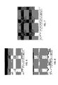
- the microphotographs of FIGS. 3 and 4 evidence poor adhesion and through-cracks in a YSZ TBC having a thickness of about 100 micrometers.
- the coating was formed on a PtAl diffusion bond coat by a sol-gel process using zirconium chloride hexahydrate (ZrOCl 2 -8H 2 O) and yttrium methoxide (C 9 H 21 O 6 Y) as precursors for zirconia (ZrO 2 ) and yttria (Y 2 O 3 ), respectively, in which particles (d50 of about 130 nm) of YSZ (8 molar percent yttria) were dispersed.
- These coatings also tend to prematurely spall when subjected to thermal cycling, as evidenced by the microphotograph of FIG. 5 , which shows a YSZ TBC formed by the same process as that used to form the coating of FIGS. 3 and 4 .
- the coating had been subject to thermal cycling employing one-hour cycles between room temperature and about 2000°F (about 1090°C), and had sustained about twenty percent spallation at the completion of about sixty cycles.
- the present invention provides coating systems and colloidal-based coating processes, by which a ceramic coating can be entirely formed from a colloidal-based process to have a thickness that would ordinarily crack and spall when deposited on a metallic substrate and subjected to thermal cycling. Resistance to cracking and spallation are promoted through the inclusion of a ceramic film that is formed to have a limited thickness and contain ceramic particles having narrowly tailored size, reactivity and composition.
- the process includes forming a precursor primer layer on and contacting a surface region of a component, and then forming at least one precursor coating layer on and contacting the precursor primer layer.
- the precursor primer layer has a thickness of up to about 30 micrometers and comprises a precursor of a first ceramic material having a predominant constituent and a dispersion of particles of the first ceramic material.
- the particles of the precursor primer layer have a median particle size (d50) of about 20 to about 100 nanometers.
- the precursor coating layer has a thickness of greater than the precursor primer layer and comprises a precursor of a second ceramic material having the same predominant constituent as the first ceramic material and a dispersion of particles of the second ceramic material.
- the precursor primer and coating layers are then heated to form a ceramic film from the precursor primer layer and a ceramic coating layer from the precursor coating layer.
- the ceramic film has a thickness of up to 30 micrometers and consists essentially of the particles of the first ceramic material in a matrix of the first ceramic material.
- the ceramic coating layer has a thickness of greater than the ceramic film and consists essentially of the particles of the second ceramic material in a matrix of the second ceramic material.
- the ceramic coating layer of the coating system may be, as nonlimiting examples, a TBC, a corrosion or erosion mitigation coating, a hermetic seal, etc., and applied to gas turbine components as well as a wide variety of other components that benefit from a ceramic coating
- a notable aspect of the process and the resulting coating system is that the particle size and thickness of the precursor primer layer and the thickness of the resulting ceramic film are limited to achieve sufficient adhesion of the ceramic coating layer that enables the ceramic coating layer to resist spallation and survive thermal cycling when applied to thicknesses of up to at least 200 micrometers.
- the effectiveness of the ceramic film has been shown by producing and testing coating systems with and without the ceramic film of this invention, with those including the ceramic film being able to exhibit thermal cycle lives of at least four times greater than those without.
- the ability of the ceramic film to provide a robust platform and bond for thick ceramic coatings applied by colloid-based processes enables a significant cost advantage relative to PVD and other typical processes that are commonly employed to deposit TBCs and similar thick ceramic coatings, but are limited by line-of-sight and other geometric constraints.
- FIG. 1 schematically represents a cross-sectional view of a substrate having a coating system according to an embodiment of the present invention, in which a ceramic film adheres a ceramic coating to a metallic bond coat on the substrate.
- FIG. 2 is a representation of the chemical composition of the ceramic film and the ceramic coating of FIG. 1 .
- FIG. 3 is a microphotograph of a ceramic coating formed from a sol-gel in accordance with prior art practices.
- FIG. 4 is a magnified microphotograph of the ceramic coating of FIG. 3 , evidencing poor adhesion and through-cracks in the coating as deposited.
- FIG. 5 is a microphotograph of the ceramic coating of FIG. 3 following thermal cycling, evidencing further cracking and spallation of the coating.
- FIG. 6 is a microphotograph of a ceramic coating formed from a sol-gel and deposited on a ceramic film in accordance with an embodiment of the present invention.
- FIG. 7 is a magnified microphotograph of the ceramic coating of FIG. 6 , evidencing that the ceramic coating is essentially crack-free and well-adhered to the ceramic film as deposited.
- FIG. 8 is a microphotograph of the ceramic coating of FIG. 6 following thermal cycling, evidencing that the ceramic coating remained essentially crack-free and well-adhered to the ceramic film.
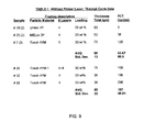
- FIGS. 9 , 10 and 11 summarize test specimens and results obtained during investigations leading to the present invention.
- FIG. 1 schematically represents a metallic substrate region 12 of a component 10, which may be a gas turbine engine component, particular examples of which include hot gas path components such as turbine blade and turbine vanes, though other applications are also foreseeable and within the scope of the invention.
- the substrate region 12 is shown protected by a coating system that includes an outer ceramic coating 14 adhered to the substrate region 12 by a metallic bond coat 16.
- the substrate region 12 is preferably a metallic material, for example, a nickel-base or cobalt-base superalloy, though various other materials can also be protected in accordance with the invention.
- FIG. 1 depicts the bond coat 16 as having a continuous and adherent oxide scale 18 on its surface to promote the adhesion of the ceramic coating 14 to the bond coat 16 and the underlying substrate region 12.
- the oxide scale 18 can be formed by subjecting the bond coat 16 to an oxidizing environment, such that the scale 18 may be termed a thermally-grown oxide (TGO).
- TGO thermally-grown oxide
- the thickness of the oxide scale 18 will vary depending on the composition and processing of the bond coat 16, though thicknesses of about 100 to about 500 nanometers are typical and acceptable.
- the bond coat 16 is preferably present in the coating system to provide environmental protection to the underlying substrate region 12 of the component 10, though in some cases the bond coat 16 could be omitted if the composition of the substrate region 12 is sufficiently resistant to oxidation, corrosion, or other sources of environmental attack, and/or is capable of forming a continuous and adherent oxide scale on its surface.
- the bond coat 16 is preferably an aluminum-containing composition capable of forming alumina as the oxide scale 18 on its surface when subjected to an oxidizing environment, though the use of other bond coat compositions is also foreseeable.
- Preferred compositions for the bond coat 16 include aluminide coatings such as a platinum-modified aluminide (PtAl) diffusion coating or a beta-phase (NiAl) nickel aluminide overlay coating, though the use of other bond coat compositions is foreseeable, for example, an MCrAlX overlay coating alloy (where M is iron, cobalt and/or nickel, and X is yttrium, rare earth metals, and/or reactive metals).
- the bond coat 16 is a diffusion aluminide coating
- a suitable process for forming bond coat 16 is to deposit and diffuse aluminum into the surface of the substrate region 12 to form aluminide intermetallics on and beneath the surface of the substrate region 12.
- the bond coat 16 is an overlay coating
- the desired composition for the bond coat 16 can be directly deposited on the surface of the substrate region 12 by plasma spraying or another physical vapor deposition (PVD) process, with minimal interdiffusion with the substrate region 12. It is contemplated that other processes could be used to apply the bond coat 16 to the substrate region 12.
- the thickness of the bond coat 16 will depend on its composition and type.
- a typical thickness is up to about 20 micrometers, for example, about 4 to about 12 micrometers.
- Other aspects of bond coats, including their compositions and deposition processes, are well known in the prior art and therefore will not be described in any further detail here.
- the ceramic coating 14 may be employed as a thermal barrier coating (TBC), a corrosion or erosion mitigation coating, a hermetic seal, or any other application in which an adherent ceramic coating could be utilized.
- TBCs include ceramics, and particularly zirconia (ZrO 2 ) at least partially stabilized with yttria (Y 2 O 3 ) (for example, about 4 to about 20 weight percent yttria), though the use of other or additional stabilizers is also within the scope of the invention.
- Zirconia partially stabilized by about 7 weight percent (about 4 molar percent) yttria is the most widely used TBC material because of its combination of low thermal conductivity, stability, good mechanical properties, and wear resistance, and therefore is believed to be a particularly suitable ceramic material for the ceramic coating 14 of the invention, though yttria contents of less than and greater than four molar percent are also within the scope of this invention.
- the thickness of the ceramic coating 14 will typically be in a range of about 250 micrometers to about 750 micrometers, with lesser and greater thicknesses also foreseeable.
- the ceramic coating 14 is formed by a sol-gel, colloidal, or slurry-based process, by which a solution containing a precursor of the desired ceramic material for the coating 14 is applied to form at least one and preferably a plurality of precursor coating layers, which then undergo thermal processing to convert the precursor to the ceramic material.
- a solution containing a precursor of the desired ceramic material for the coating 14 is applied to form at least one and preferably a plurality of precursor coating layers, which then undergo thermal processing to convert the precursor to the ceramic material.
- Particularly suitable precursors for the sol-gel process include, but are not limited to, acetylacetonate, oxychloride-hydroxyoxide, nitrate salt, and organometallic compounds.
- the precursor preferably contains a dispersion of ceramic particles, which remain dispersed in the ceramic coating 14 following thermal processing of the precursor coating layers.
- the thickness of a ceramic coating formed by a sol-gel process has been severely limited, often not more than about 10 micrometers, due to the tendency for the coating to crack and spall, as evidenced by FIGS. 3 through 5 .
- the lack of robust attachment in the prior art sol-gel TBC of FIGS. 3 through 5 is believed to be primarily attributable to the colloidal particles being in suspension too far from the underlying substrate surface, and insufficient reactivity of the particles to form a strong bond with the surface.
- the present invention is intended to enable the ceramic coating 14 to be adherent at thicknesses of at least 200 micrometers, and preferably at least about 500 micrometers or more, through the inclusion in the coating system of a ceramic film 20 that overlies the bond coat 16 and directly contacts the ceramic coating 14, as schematically represented in FIG. 1 (not to scale).
- the ceramic film 20 is preferably formed by a colloidal, slurry, or sol-gel based process, in which ceramic particles are dispersed in a precursor of a ceramic material, after which the resulting primer mixture is applied to the surface of the bond coat 16 to form a precursor primer layer.
- Particularly suitable precursors for colloidal and slurry-based processes include, but are not limited to, cellulose acetate, polyvinyl alcohol, polyvinyl chloride, acrylics, butyl alcohol, polyethyl oxides, polyvinyl propylene, phenolic resins, water-soluble resins, and alcohol-soluble resins.
- the colloidal or slurry-based primer mixture can be applied in a variety of manners, for example, those typical of sol gel based coatings such as spraying, dipping, or brushing, after which the resulting precursor primer layer is heated to convert the precursor to form a matrix of the ceramic material containing the dispersed ceramic particles.
- Drastically improved adhesion of the ceramic coating 14 has been achieved if the particle size and thickness of the precursor primer layer and the thickness of the resulting ceramic film 20 are limited.
- the composition, reactivity, and surface morphology of the particles are also believed to be relevant.
- the composition and reactivity of the particles are believed to provide enhanced chemical bonding of the ceramic coating 14, likely as a result of an improved thermally-grown oxide scale 18.
- the degree and strength of the bond between the ceramic film 20 and the oxide scale 18, as well as the bond between the ceramic film 20 and ceramic coating 14 are believed to be controlled by the composition and thickness of the ceramic film 20.
- the ceramic film 20 is physically distinguishable from the ceramic coating 14 and any layers that form the coating 14, even though the ceramic film 20 and coating 14 may be formed, and preferably are formed, to have the same predominant constituent.
- both may contain more zirconia by molar percent than any other individual constituent, as is the case with zirconia at least partially stabilized with yttria, for example, about 4 to about 20 weight percent yttria.
- both the ceramic film 20 and the coating 14 may have ceramic matrices consisting of YSZ containing the same molar percent of yttria. Though their matrices are both predominantly zirconia, as represented in FIG. 2 , the particles (not represented in FIG.
- the invention arises from the determination that the ceramic film 20 must have a limited thickness, contain a matrix whose composition is the same as or otherwise compatible with the matrix material of the coating 14, and contain a dispersion of particles of a limited size and particular composition that enable the ceramic film 20 to bond well to the coating 14 and the underlying metallic surface (such as the bond coat 16).
- the ability of the ceramic film 20 to enhance bonding of a relatively thick ceramic coating to a metallic substrate has been demonstrated using YSZ as the composition for the matrices and particles of the ceramic coating 14 and ceramic film 20, though it is believed that other coating compositions will also benefit from the ceramic film 20.
- Superior adhesion resulting from the inclusion of the ceramic film 20 was demonstrated through increased thermal cycle life and tensile adhesion strength, for example, in comparison to the TBC coating of FIGS. 3 through 5 , which was applied by a sol gel process but failed very early or prematurely in thermal cycle testing.
- thermal cycling furnace cycle test, or FCT
- adhesion tests were performed on specimens produced to have coatings with and without ceramic films within the scope of of this invention.
- the coating systems were deposited on buttons formed of either PtAl or NiAl intermetallic.
- the precursor solutions for the matrices of the ceramic coatings and (if present) the ceramic films were a sol-gel made up of a binder mixture of ethyl cellulose and terpineol combined with zirconium 2,4-pentanedionate and yttrium 2,4-pentanedionate as precursors for zirconia (ZrO 2 ) and yttria (Y 2 O 3 ), respectively.
- YSZ particles were dispersed in each of the precursor solutions to form either a primer mixture or a coating mixture.
- YSZ particles combined with the precursor solution to form the primer mixtures included YSZ containing about 4 molar percent yttria in amounts of about 5 to about 40 weight percent of the primer mixture.
- Median particle sizes (d50) ranged from about 20 to about 150 nanometers, particle surface areas ranged from about 9 to about 20 m 2 /g, and particle crystalline size ranged from about 5 to about 50 nanometers.
- the particles for the primer mixtures were selected for their small primary particle size, low crystallinity and high reactivity (attributed to surface area and crystalline size), which was theorized to promote sinterability of the particles and promote a more robust attachment to a thermally grown oxide (TGO) scale on the button specimens.
- TGO thermally grown oxide
- YSZ particles combined with the precursor solution to form coating mixtures for the investigation (and, after application and conversion, will form individual ceramic layers that in combination define a ceramic coating, such as the ceramic coating 14 in FIG. 1 ) included YSZ containing about 4 molar percent yttria in amounts of about 10 to about 40 weight percent of the coating mixture.
- Median particle sizes (d50) ranged from about 50 nanometers to about 10 micrometers, and particle surface areas ranged from about 11 to about 117 m 2 /g.
- the particles of the coating mixtures were selected to be of lower reactivity and lower sinterability, which was theorized would control shrinkage and reduce delamination during conversion of the precursor coating layers to ceramic coating layers.
- buttons Prior to application of the primer and coating mixtures, the buttons were subjected to a two-hour oxidation treatment to develop an alumina scale having a thickness of about 100 to about 250 nanometers.
- the primer mixtures were deposited on each button by spraying to form a single layer having a thickness of about 4 to about 20 micrometers.
- the coating mixtures were deposited by spraying to form multiple layers, each having a thickness of about 6 to about 12 micrometers.
- buttons were subjected to thermal treatments at about 1000°C to burn off the binder and convert the precursors, yielding ceramic coating layers (formed from the precursor coating layers) and, if present, ceramic films (formed from the precursor primer layers) having essentially identical YSZ matrices containing a dispersion of their respective YSZ particles.
- the resulting ceramic films had thicknesses of about 4 to about 20 micrometers, the individual ceramic coating layers had thicknesses of about 6 to about 12 micrometers, and in combination the individual ceramic coating layers formed ceramic coatings having thicknesses of about 100 to about 500 micrometers.
- the test conditions of the thermal cycling investigation included one-hour cycles between room temperature and about 2000°F (about 1090°C). Individual buttons were removed from thermal cycling once its coating system had sustained about twenty percent spallation. The adhesion strengths of the coating systems (normal to the surface of the buttons) were measured using known tensile adhesion testing techniques, in which an increasing tensile load was applied until tensile fracture occurred.
- Tables I, II and III of FIGS. 9 , 10 and 11 Selected test specimens and results from the investigation are summarized in Tables I, II and III of FIGS. 9 , 10 and 11 .
- Tosoh 4YM-1 and Tosoh 4YM identify powders of zirconia stabilized by about four molar percent yttria (hereinafter, M%YSZ is used to indicate yttria contents in molar percent).
- the powders were obtained from the Tosoh Corporation, had a primary crystal size of about 25 nm, and were milled to obtain a mean particle size (d50) of about 60 nm.
- Unitec 4Y is a 4M%YSZ powder commercially-available from Unitec Ceramics, Ltd.
- MELox 3Y is a 3M%YSZ powder commercially-available from MEL Chemicals, Inc., (primary crystal size of about 62 nm, mean particle size (d50) of about 250 nm)
- Tosoh 4Y Calcined is the aforementioned Tosoh 4YM after heat treatment at about 1100°C calcine as a loose powder to partially sinter the particles.
- V-0006 is a commercial polymeric binder system. The number of layers listed in Tables I, II and III indicate the number of layers deposited prior to a curing step, each layer being formed by a single spray pass. As noted above, after deposition all samples were processed at about 1000°C to burn off the binders and convert the precursor primer and coating layers.
- Tables I and II evidence that FCT lives were improved by a factor of about two to about four by the presence of a ceramic film incorporated into the coating system (Table II), in comparison to those coating systems lacking a ceramic film (Table I). Furthermore, ceramic films exceeding thirty micrometers in thickness (not represented in the Tables) fractured as a result of volumetric shrinkage during firing, resulting in spallation of their overlying ceramic coatings during FCT testing.
- FIGS. 6 and 7 exemplify one of the coating systems produced and tested during the investigation.
- the coating system has a thick ceramic coating (about 150 micrometers) overlying a thin ceramic film (about 8 micrometers).
- the ceramic coating (corresponding to the ceramic coating 14 in FIG.
- the ceramic film (corresponding to the ceramic film 20 in FIG. 1 ) has the same YSZ matrix as the ceramic coating, but contained about 20 weight percent of the Tosoh 4YM YSZ particles with a median particle size (d50) of about 40 to about 70 nanometers, and particle surface area of about 15 to about 20 m 2 /g.
- the ceramic film (corresponding to the ceramic film 20 in FIG. 1 ) has the same YSZ matrix as the ceramic coating, but contained about 20 weight percent of the Tosoh 4YM YSZ particles with a median particle size (d50) of about 40 to about 70 nanometers, and particle surface area of about 15 to about 20 m 2 /g.
- the ceramic coating can be seen to be crack-free and well adhered to the ceramic film, which is in stark contrast to the prior art coating system of FIGS. 3 and 4 .
- this coating was crack-free and well-adhered when it was sectioned after completing 100 thermal cycles, as evidenced by FIG. 8 .
- Such results are again in contrast to the prior art coating system shown in FIG. 5 .
- ceramic particles within the ceramic film 20 preferably have a median particle size (d50) of about 20 to about 100 nanometers, more preferably about 50 to about 100 nanometers.
- the particles preferably constitute about 10 to about 40 weight percent, and in the ceramic film 20 the particles preferably constitute about 15 to about 30 weight percent, more preferably about 20 to about 25 weight percent.
- the precursor primer layer should be deposited to a thickness of not more than 30 micrometers, preferably not more than 20 micrometers, and more preferably about 4 to about 20 micrometers, to yield a ceramic film having a thickness of not more than 30 micrometers, preferably not more than 20 micrometers, and more preferably about 4 to about 20 micrometers. If these limitations are met, a crack-free and well-adhered ceramic coating 14 can be formed by depositing a sol-gel or other suitable colloid-based coating mixture to have a thickness of greater than the precursor primer layer to yield a ceramic coating 14 having a thickness of greater than the ceramic film.
- preferred materials for the ceramic matrices and particles of the ceramic coating 14 and film 20 include YSZ, particularly YSZ containing about 4 molar percent yttria, and the thickness of the ceramic coating 14 will typically be at least 200 micrometers, such as in a range of about 250 up to about 750 micrometers and, in some cases, more preferably about 250 to about 500 micrometers.
Landscapes
- Chemical & Material Sciences (AREA)
- Engineering & Computer Science (AREA)
- Materials Engineering (AREA)
- Mechanical Engineering (AREA)
- Organic Chemistry (AREA)
- Chemical Kinetics & Catalysis (AREA)
- Thermal Sciences (AREA)
- Physics & Mathematics (AREA)
- Inorganic Chemistry (AREA)
- Metallurgy (AREA)
- General Chemical & Material Sciences (AREA)
- Dispersion Chemistry (AREA)
- Nanotechnology (AREA)
- Ceramic Engineering (AREA)
- Turbine Rotor Nozzle Sealing (AREA)
- Other Surface Treatments For Metallic Materials (AREA)
- Devices For Post-Treatments, Processing, Supply, Discharge, And Other Processes (AREA)
Abstract
Description
- The present invention generally relates to coating systems and methods for their deposition. More particularly, this invention relates to a process for forming a ceramic coating using a colloidal-based process, such as a sol (colloidal suspension) or sol-gel, and particularly a process in which the entire ceramic coating is formed from a colloidal-based process to have a thickness that would ordinarily crack and spall when deposited on a metallic substrate and subjected to thermal cycling. Resistance to cracking and spallation are promoted with a ceramic film of limited thickness and formed from a sol or slurry containing particles having narrowly tailored size, reactivity and composition.
- The maximum turbine inlet temperature of a gas turbine is limited by the ability of the hot gas path components, especially turbine components such as vanes and blades, to withstand the heat, oxidation and corrosion effects of the hot gas stream and maintain sufficient mechanical strength. Consequently, there exists a continuing need to find advanced material systems for use in components that will function satisfactorily in high performance gas turbines that operate at higher temperatures and stresses. A common approach is to protect surfaces of components with environmentally and thermally protective coating systems. Such coating systems typically include a metallic bond coat that environmentally protects the component surface and adheres a thermal barrier coating (TBC) that provides an insulating effect but offers little resistance to oxidation, erosion, and corrosion. TBC's are typically formed of a ceramic material, a widely-used example of which is yttria-stabilized zirconia (YSZ). The ability of a metallic bond coat to adhere a ceramic TBC and protect the underlying substrate is typically promoted through the formation of an adherent oxide scale, such as a thin layer of aluminum oxide (alumina), on its surface, which chemically bonds the ceramic TBC to the bond coat. For this purpose, various bond coats have been proposed, notable examples of which include diffusion coatings that contain aluminum intermetallics (predominantly beta-phase nickel aluminide (β-NiAl) and platinum aluminides (PtAl)), and overlay coatings such as MCrAlX (where M is iron, cobalt and/or nickel, and X is yttrium, rare earth metals, and/or reactive metals).
- The service lives of coating systems of the type described above are typically limited at high temperatures due to excessive growth of the oxide scale on the bond coat and flaws which develop within the interfacial zone between the bond coat and ceramic TBC. Thermally-induced deterioration of the interfacial zone coupled with stresses induced by thermal transients, thermal expansion mismatch between the ceramic TBC and the metallic bond coat and substrate, and oxide growth eventually lead to spallation of the TBC. Considerable advances have been made in the spallation resistance of TBCs through processing and compositional modifications to bond coats and TBCs, which are typically deposited by techniques such as thermal spraying and physical vapor deposition (PVD), particularly electron beam physical vapor deposition (EBPVD). However, these techniques have disadvantages and limitations, such as relatively high costs and being limited to line-of-sight deposition, the latter of which complicates the ability to protect components such as nozzle doublets that have complex geometries.
- One approach being explored to overcome these disadvantages and limitations is the use of sol-based and colloidal-based processes, including sol-gels, to deposit TBCs. As well known in the art, colloidal-based processes entail depositing multiple layers of a liquid precursor, such as a metal alkoxide, metal chloride, or organometallic, of the desired ceramic for the TBC. The precursor may also contain particles of the desired ceramic (often referred to as a colloid). After drying, the deposited layers are heated to convert the precursor to the desired ceramic. Deposition of the precursor layers can be by immersion, spraying, brushing, etc., which allow the coating of surfaces that would be otherwise difficult to coat by a line-of-sight process. However, TBCs and other ceramic coatings formed from colloidal-based processes typically exhibit low tensile adhesion and cracking. For example, the microphotographs of
FIGS. 3 and 4 evidence poor adhesion and through-cracks in a YSZ TBC having a thickness of about 100 micrometers. The coating was formed on a PtAl diffusion bond coat by a sol-gel process using zirconium chloride hexahydrate (ZrOCl2-8H2O) and yttrium methoxide (C9H21O6Y) as precursors for zirconia (ZrO2) and yttria (Y2O3), respectively, in which particles (d50 of about 130 nm) of YSZ (8 molar percent yttria) were dispersed. These coatings also tend to prematurely spall when subjected to thermal cycling, as evidenced by the microphotograph ofFIG. 5 , which shows a YSZ TBC formed by the same process as that used to form the coating ofFIGS. 3 and 4 . The coating had been subject to thermal cycling employing one-hour cycles between room temperature and about 2000°F (about 1090°C), and had sustained about twenty percent spallation at the completion of about sixty cycles. - There are ongoing efforts to enhance the bonding of colloidal-based coatings. Typical examples include treatments to roughen, oxidize, or adjust the pH of the substrate surface to increase bond strength. These methods have been met with limited success, and therefore additional and alternative steps have been tried as well, such as the use of chemically compatible bond coats and the application of a thin film of alumina to the bond coat prior to applying the TBC coating, the latter of which is intended to enhance the growth of oxide into the TBC coating. However, these methods have also achieved limited success, with the result that ceramic coatings deposited by sol-gel and other colloidal-based processes are typically limited to thicknesses of not greater than about 50 micrometers, and often less than 25 micrometers.
- The present invention provides coating systems and colloidal-based coating processes, by which a ceramic coating can be entirely formed from a colloidal-based process to have a thickness that would ordinarily crack and spall when deposited on a metallic substrate and subjected to thermal cycling. Resistance to cracking and spallation are promoted through the inclusion of a ceramic film that is formed to have a limited thickness and contain ceramic particles having narrowly tailored size, reactivity and composition.
- According to a first aspect of the invention, the process includes forming a precursor primer layer on and contacting a surface region of a component, and then forming at least one precursor coating layer on and contacting the precursor primer layer. The precursor primer layer has a thickness of up to about 30 micrometers and comprises a precursor of a first ceramic material having a predominant constituent and a dispersion of particles of the first ceramic material. The particles of the precursor primer layer have a median particle size (d50) of about 20 to about 100 nanometers. The precursor coating layer has a thickness of greater than the precursor primer layer and comprises a precursor of a second ceramic material having the same predominant constituent as the first ceramic material and a dispersion of particles of the second ceramic material. The precursor primer and coating layers are then heated to form a ceramic film from the precursor primer layer and a ceramic coating layer from the precursor coating layer. The ceramic film has a thickness of up to 30 micrometers and consists essentially of the particles of the first ceramic material in a matrix of the first ceramic material. The ceramic coating layer has a thickness of greater than the ceramic film and consists essentially of the particles of the second ceramic material in a matrix of the second ceramic material.
- Another aspect of the invention is a coating system formed by the process described above, as well as components protected by such a coating system. The ceramic coating layer of the coating system may be, as nonlimiting examples, a TBC, a corrosion or erosion mitigation coating, a hermetic seal, etc., and applied to gas turbine components as well as a wide variety of other components that benefit from a ceramic coating
- A notable aspect of the process and the resulting coating system is that the particle size and thickness of the precursor primer layer and the thickness of the resulting ceramic film are limited to achieve sufficient adhesion of the ceramic coating layer that enables the ceramic coating layer to resist spallation and survive thermal cycling when applied to thicknesses of up to at least 200 micrometers. The effectiveness of the ceramic film has been shown by producing and testing coating systems with and without the ceramic film of this invention, with those including the ceramic film being able to exhibit thermal cycle lives of at least four times greater than those without. The ability of the ceramic film to provide a robust platform and bond for thick ceramic coatings applied by colloid-based processes enables a significant cost advantage relative to PVD and other typical processes that are commonly employed to deposit TBCs and similar thick ceramic coatings, but are limited by line-of-sight and other geometric constraints.
- Other aspects and advantages of this invention will be better appreciated from the following detailed description.
-
FIG. 1 schematically represents a cross-sectional view of a substrate having a coating system according to an embodiment of the present invention, in which a ceramic film adheres a ceramic coating to a metallic bond coat on the substrate. -
FIG. 2 is a representation of the chemical composition of the ceramic film and the ceramic coating ofFIG. 1 . -
FIG. 3 is a microphotograph of a ceramic coating formed from a sol-gel in accordance with prior art practices. -
FIG. 4 is a magnified microphotograph of the ceramic coating ofFIG. 3 , evidencing poor adhesion and through-cracks in the coating as deposited. -
FIG. 5 is a microphotograph of the ceramic coating ofFIG. 3 following thermal cycling, evidencing further cracking and spallation of the coating. -
FIG. 6 is a microphotograph of a ceramic coating formed from a sol-gel and deposited on a ceramic film in accordance with an embodiment of the present invention. -
FIG. 7 is a magnified microphotograph of the ceramic coating ofFIG. 6 , evidencing that the ceramic coating is essentially crack-free and well-adhered to the ceramic film as deposited. -
FIG. 8 is a microphotograph of the ceramic coating ofFIG. 6 following thermal cycling, evidencing that the ceramic coating remained essentially crack-free and well-adhered to the ceramic film. -
FIGS. 9 ,10 and11 summarize test specimens and results obtained during investigations leading to the present invention. -
FIG. 1 schematically represents ametallic substrate region 12 of acomponent 10, which may be a gas turbine engine component, particular examples of which include hot gas path components such as turbine blade and turbine vanes, though other applications are also foreseeable and within the scope of the invention. Thesubstrate region 12 is shown protected by a coating system that includes an outerceramic coating 14 adhered to thesubstrate region 12 by ametallic bond coat 16. Thesubstrate region 12 is preferably a metallic material, for example, a nickel-base or cobalt-base superalloy, though various other materials can also be protected in accordance with the invention.FIG. 1 depicts thebond coat 16 as having a continuous andadherent oxide scale 18 on its surface to promote the adhesion of theceramic coating 14 to thebond coat 16 and theunderlying substrate region 12. Theoxide scale 18 can be formed by subjecting thebond coat 16 to an oxidizing environment, such that thescale 18 may be termed a thermally-grown oxide (TGO). The thickness of theoxide scale 18 will vary depending on the composition and processing of thebond coat 16, though thicknesses of about 100 to about 500 nanometers are typical and acceptable. Thebond coat 16 is preferably present in the coating system to provide environmental protection to theunderlying substrate region 12 of thecomponent 10, though in some cases thebond coat 16 could be omitted if the composition of thesubstrate region 12 is sufficiently resistant to oxidation, corrosion, or other sources of environmental attack, and/or is capable of forming a continuous and adherent oxide scale on its surface. - The
bond coat 16 is preferably an aluminum-containing composition capable of forming alumina as theoxide scale 18 on its surface when subjected to an oxidizing environment, though the use of other bond coat compositions is also foreseeable. Preferred compositions for thebond coat 16 include aluminide coatings such as a platinum-modified aluminide (PtAl) diffusion coating or a beta-phase (NiAl) nickel aluminide overlay coating, though the use of other bond coat compositions is foreseeable, for example, an MCrAlX overlay coating alloy (where M is iron, cobalt and/or nickel, and X is yttrium, rare earth metals, and/or reactive metals). As known in the art, if thebond coat 16 is a diffusion aluminide coating, a suitable process for formingbond coat 16 is to deposit and diffuse aluminum into the surface of thesubstrate region 12 to form aluminide intermetallics on and beneath the surface of thesubstrate region 12. If thebond coat 16 is an overlay coating, the desired composition for thebond coat 16 can be directly deposited on the surface of thesubstrate region 12 by plasma spraying or another physical vapor deposition (PVD) process, with minimal interdiffusion with thesubstrate region 12. It is contemplated that other processes could be used to apply thebond coat 16 to thesubstrate region 12. The thickness of thebond coat 16 will depend on its composition and type. For PtAl and NiAl bond coats, a typical thickness is up to about 20 micrometers, for example, about 4 to about 12 micrometers. Other aspects of bond coats, including their compositions and deposition processes, are well known in the prior art and therefore will not be described in any further detail here. - The
ceramic coating 14 may be employed as a thermal barrier coating (TBC), a corrosion or erosion mitigation coating, a hermetic seal, or any other application in which an adherent ceramic coating could be utilized. Typical materials for TBCs include ceramics, and particularly zirconia (ZrO2) at least partially stabilized with yttria (Y2O3) (for example, about 4 to about 20 weight percent yttria), though the use of other or additional stabilizers is also within the scope of the invention. Zirconia partially stabilized by about 7 weight percent (about 4 molar percent) yttria is the most widely used TBC material because of its combination of low thermal conductivity, stability, good mechanical properties, and wear resistance, and therefore is believed to be a particularly suitable ceramic material for theceramic coating 14 of the invention, though yttria contents of less than and greater than four molar percent are also within the scope of this invention. For use as a TBC, the thickness of theceramic coating 14 will typically be in a range of about 250 micrometers to about 750 micrometers, with lesser and greater thicknesses also foreseeable. - According to a preferred aspect of the invention, the
ceramic coating 14 is formed by a sol-gel, colloidal, or slurry-based process, by which a solution containing a precursor of the desired ceramic material for thecoating 14 is applied to form at least one and preferably a plurality of precursor coating layers, which then undergo thermal processing to convert the precursor to the ceramic material. Particularly suitable precursors for the sol-gel process include, but are not limited to, acetylacetonate, oxychloride-hydroxyoxide, nitrate salt, and organometallic compounds. The precursor preferably contains a dispersion of ceramic particles, which remain dispersed in theceramic coating 14 following thermal processing of the precursor coating layers. Previously, the thickness of a ceramic coating formed by a sol-gel process has been severely limited, often not more than about 10 micrometers, due to the tendency for the coating to crack and spall, as evidenced byFIGS. 3 through 5 . Though not wishing to be held to any particular theory, the lack of robust attachment in the prior art sol-gel TBC ofFIGS. 3 through 5 is believed to be primarily attributable to the colloidal particles being in suspension too far from the underlying substrate surface, and insufficient reactivity of the particles to form a strong bond with the surface. - The present invention is intended to enable the
ceramic coating 14 to be adherent at thicknesses of at least 200 micrometers, and preferably at least about 500 micrometers or more, through the inclusion in the coating system of aceramic film 20 that overlies thebond coat 16 and directly contacts theceramic coating 14, as schematically represented inFIG. 1 (not to scale). Theceramic film 20 is preferably formed by a colloidal, slurry, or sol-gel based process, in which ceramic particles are dispersed in a precursor of a ceramic material, after which the resulting primer mixture is applied to the surface of thebond coat 16 to form a precursor primer layer. Particularly suitable precursors for colloidal and slurry-based processes include, but are not limited to, cellulose acetate, polyvinyl alcohol, polyvinyl chloride, acrylics, butyl alcohol, polyethyl oxides, polyvinyl propylene, phenolic resins, water-soluble resins, and alcohol-soluble resins. The colloidal or slurry-based primer mixture can be applied in a variety of manners, for example, those typical of sol gel based coatings such as spraying, dipping, or brushing, after which the resulting precursor primer layer is heated to convert the precursor to form a matrix of the ceramic material containing the dispersed ceramic particles. Drastically improved adhesion of theceramic coating 14 has been achieved if the particle size and thickness of the precursor primer layer and the thickness of the resultingceramic film 20 are limited. The composition, reactivity, and surface morphology of the particles are also believed to be relevant. The composition and reactivity of the particles are believed to provide enhanced chemical bonding of theceramic coating 14, likely as a result of an improved thermally-grown oxide scale 18. Furthermore, the degree and strength of the bond between theceramic film 20 and theoxide scale 18, as well as the bond between theceramic film 20 andceramic coating 14, are believed to be controlled by the composition and thickness of theceramic film 20. - The
ceramic film 20 is physically distinguishable from theceramic coating 14 and any layers that form thecoating 14, even though theceramic film 20 andcoating 14 may be formed, and preferably are formed, to have the same predominant constituent. For example, both may contain more zirconia by molar percent than any other individual constituent, as is the case with zirconia at least partially stabilized with yttria, for example, about 4 to about 20 weight percent yttria. As a particular example, both theceramic film 20 and thecoating 14 may have ceramic matrices consisting of YSZ containing the same molar percent of yttria. Though their matrices are both predominantly zirconia, as represented inFIG. 2 , the particles (not represented inFIG. 2 ) dispersed in theceramic film 20 must differ from the particles dispersed in thecoating 14 in order for theceramic film 20 to promote the thermal growth of anoxide scale 18 that is capable of achieving adequate adhesion of thecoating 14. This difference exists even if theceramic film 20 and the first deposited layer of thecoating 14 are both formed by sol-gel (colloid-based) processes, and even if theceramic film 20 andcoating 14 contain the same matrix material and/or particles of the same composition. Notably, attempts to promote the adhesion of aceramic coating 14 formed using a colloid-based process (such as sol-gel) by simply reducing the thickness of the first deposited layer of thecoating 14 have not resulted in adequate adhesion. - In view of the above, the invention arises from the determination that the
ceramic film 20 must have a limited thickness, contain a matrix whose composition is the same as or otherwise compatible with the matrix material of thecoating 14, and contain a dispersion of particles of a limited size and particular composition that enable theceramic film 20 to bond well to thecoating 14 and the underlying metallic surface (such as the bond coat 16). - The ability of the
ceramic film 20 to enhance bonding of a relatively thick ceramic coating to a metallic substrate has been demonstrated using YSZ as the composition for the matrices and particles of theceramic coating 14 andceramic film 20, though it is believed that other coating compositions will also benefit from theceramic film 20. Superior adhesion resulting from the inclusion of theceramic film 20 was demonstrated through increased thermal cycle life and tensile adhesion strength, for example, in comparison to the TBC coating ofFIGS. 3 through 5 , which was applied by a sol gel process but failed very early or prematurely in thermal cycle testing. In a series of tests performed withceramic films 20 of various thicknesses, coating systems incorporating theceramic film 20 exhibited increased thermal cycle performance as well as increased tensile adhesion, whereas coatings without theceramic film 20 but otherwise identical in composition and construction did not demonstrate an acceptable tensile adhesion level and prematurely spalled during thermal cycling. - In an investigation leading to the present invention, thermal cycling (furnace cycle test, or FCT) and adhesion tests were performed on specimens produced to have coatings with and without ceramic films within the scope of of this invention. The coating systems were deposited on buttons formed of either PtAl or NiAl intermetallic. The precursor solutions for the matrices of the ceramic coatings and (if present) the ceramic films were a sol-gel made up of a binder mixture of ethyl cellulose and terpineol combined with
zirconium 2,4-pentanedionate andyttrium 2,4-pentanedionate as precursors for zirconia (ZrO2) and yttria (Y2O3), respectively. YSZ particles were dispersed in each of the precursor solutions to form either a primer mixture or a coating mixture. - For the investigation, YSZ particles combined with the precursor solution to form the primer mixtures (which, after application and conversion, will form a ceramic film, such as the
ceramic film 20 inFIG. 1 ) included YSZ containing about 4 molar percent yttria in amounts of about 5 to about 40 weight percent of the primer mixture. Median particle sizes (d50) ranged from about 20 to about 150 nanometers, particle surface areas ranged from about 9 to about 20 m2/g, and particle crystalline size ranged from about 5 to about 50 nanometers. The particles for the primer mixtures (and, therefore, the precursor primer layer and the resulting ceramic film) were selected for their small primary particle size, low crystallinity and high reactivity (attributed to surface area and crystalline size), which was theorized to promote sinterability of the particles and promote a more robust attachment to a thermally grown oxide (TGO) scale on the button specimens. - YSZ particles combined with the precursor solution to form coating mixtures for the investigation (and, after application and conversion, will form individual ceramic layers that in combination define a ceramic coating, such as the
ceramic coating 14 inFIG. 1 ) included YSZ containing about 4 molar percent yttria in amounts of about 10 to about 40 weight percent of the coating mixture. Median particle sizes (d50) ranged from about 50 nanometers to about 10 micrometers, and particle surface areas ranged from about 11 to about 117 m2/g. In comparison to the particles for the primer mixtures described above, the particles of the coating mixtures (and, therefore, the precursor coating layers and the resulting ceramic coating) were selected to be of lower reactivity and lower sinterability, which was theorized would control shrinkage and reduce delamination during conversion of the precursor coating layers to ceramic coating layers. - Prior to application of the primer and coating mixtures, the buttons were subjected to a two-hour oxidation treatment to develop an alumina scale having a thickness of about 100 to about 250 nanometers. On buttons intended to have a ceramic film incorporated into their coating systems, the primer mixtures were deposited on each button by spraying to form a single layer having a thickness of about 4 to about 20 micrometers. On all buttons, the coating mixtures were deposited by spraying to form multiple layers, each having a thickness of about 6 to about 12 micrometers. Depending on the coating, one or more curing treatments were performed at a temperature of about 150°C for a duration of about fifteen minutes to eliminate the solvent and cure the binder in the primer and coating mixtures, yielding individual precursor coating layers built up directly on the oxidized surfaces of button specimens that were not coated with the primer mixture, and individual precursor coating layers built up directly on the surfaces of the precursor primer layers of button specimens that were coated with the primer mixture. Thereafter, the buttons were subjected to thermal treatments at about 1000°C to burn off the binder and convert the precursors, yielding ceramic coating layers (formed from the precursor coating layers) and, if present, ceramic films (formed from the precursor primer layers) having essentially identical YSZ matrices containing a dispersion of their respective YSZ particles. The resulting ceramic films had thicknesses of about 4 to about 20 micrometers, the individual ceramic coating layers had thicknesses of about 6 to about 12 micrometers, and in combination the individual ceramic coating layers formed ceramic coatings having thicknesses of about 100 to about 500 micrometers.
- The test conditions of the thermal cycling investigation included one-hour cycles between room temperature and about 2000°F (about 1090°C). Individual buttons were removed from thermal cycling once its coating system had sustained about twenty percent spallation. The adhesion strengths of the coating systems (normal to the surface of the buttons) were measured using known tensile adhesion testing techniques, in which an increasing tensile load was applied until tensile fracture occurred.
- Selected test specimens and results from the investigation are summarized in Tables I, II and III of
FIGS. 9 ,10 and11 . In Tables I, II and III, Tosoh 4YM-1 and Tosoh 4YM identify powders of zirconia stabilized by about four molar percent yttria (hereinafter, M%YSZ is used to indicate yttria contents in molar percent). The powders were obtained from the Tosoh Corporation, had a primary crystal size of about 25 nm, and were milled to obtain a mean particle size (d50) of about 60 nm. Also in Tables I, II and III,Unitec 4Y is a 4M%YSZ powder commercially-available from Unitec Ceramics, Ltd. under the designation Unitec-0001H (primary crystal size of about 12 nm, mean particle size (d50) of about 250 nm),MELox 3Y is a 3M%YSZ powder commercially-available from MEL Chemicals, Inc., (primary crystal size of about 62 nm, mean particle size (d50) of about 250 nm), andTosoh 4Y Calcined is the aforementioned Tosoh 4YM after heat treatment at about 1100°C calcine as a loose powder to partially sinter the particles. V-0006 is a commercial polymeric binder system. The number of layers listed in Tables I, II and III indicate the number of layers deposited prior to a curing step, each layer being formed by a single spray pass. As noted above, after deposition all samples were processed at about 1000°C to burn off the binders and convert the precursor primer and coating layers. - The data in Tables I and II evidence that FCT lives were improved by a factor of about two to about four by the presence of a ceramic film incorporated into the coating system (Table II), in comparison to those coating systems lacking a ceramic film (Table I). Furthermore, ceramic films exceeding thirty micrometers in thickness (not represented in the Tables) fractured as a result of volumetric shrinkage during firing, resulting in spallation of their overlying ceramic coatings during FCT testing.
FIGS. 6 and 7 exemplify one of the coating systems produced and tested during the investigation. The coating system has a thick ceramic coating (about 150 micrometers) overlying a thin ceramic film (about 8 micrometers). The ceramic coating (corresponding to theceramic coating 14 inFIG. 1 ) has a YSZ matrix containing about 30 weight percent of the Unitec-001H YSZ particles with a median particle size (d50) of about 50 to about 250 nanometers, and particle surface area of about 40 to about 100 m2/g. The ceramic film (corresponding to theceramic film 20 inFIG. 1 ) has the same YSZ matrix as the ceramic coating, but contained about 20 weight percent of the Tosoh 4YM YSZ particles with a median particle size (d50) of about 40 to about 70 nanometers, and particle surface area of about 15 to about 20 m2/g. In the as-deposited and fired condition shown inFIGS. 6 and 7 , the ceramic coating can be seen to be crack-free and well adhered to the ceramic film, which is in stark contrast to the prior art coating system ofFIGS. 3 and 4 . When subjected to the thermal cycling test, this coating was crack-free and well-adhered when it was sectioned after completing 100 thermal cycles, as evidenced byFIG. 8 . Such results are again in contrast to the prior art coating system shown inFIG. 5 . - From the results of the investigation, it was concluded that the composition, reactivity, size, and surface morphology of the particles in the
ceramic film 20 and the thickness of theceramic film 20 must be carefully controlled to enable aceramic coating 14 of at least 500 micrometers thickness to be crack-free and well adhered in the as-deposited condition and exhibit acceptable thermal cycling and adhesion properties. In particular, it was concluded that ceramic particles within theceramic film 20 preferably have a median particle size (d50) of about 20 to about 100 nanometers, more preferably about 50 to about 100 nanometers. In the precursor primer layer, the particles preferably constitute about 10 to about 40 weight percent, and in theceramic film 20 the particles preferably constitute about 15 to about 30 weight percent, more preferably about 20 to about 25 weight percent. Furthermore, it was concluded that the precursor primer layer should be deposited to a thickness of not more than 30 micrometers, preferably not more than 20 micrometers, and more preferably about 4 to about 20 micrometers, to yield a ceramic film having a thickness of not more than 30 micrometers, preferably not more than 20 micrometers, and more preferably about 4 to about 20 micrometers. If these limitations are met, a crack-free and well-adheredceramic coating 14 can be formed by depositing a sol-gel or other suitable colloid-based coating mixture to have a thickness of greater than the precursor primer layer to yield aceramic coating 14 having a thickness of greater than the ceramic film. For use as a TBC, preferred materials for the ceramic matrices and particles of theceramic coating 14 andfilm 20 include YSZ, particularly YSZ containing about 4 molar percent yttria, and the thickness of theceramic coating 14 will typically be at least 200 micrometers, such as in a range of about 250 up to about 750 micrometers and, in some cases, more preferably about 250 to about 500 micrometers. - While the invention has been described in terms of a preferred embodiment, it is apparent that other forms could be adopted by one skilled in the art. Therefore, the scope of the invention is to be limited only by the following claims.
Claims (15)
- A process of forming a coating system on a component, the process comprising:forming a precursor primer layer on and contacting a surface region of the component, the precursor primer layer having a thickness of up to 30 micrometers and comprising a precursor of a first ceramic material having a predominant constituent and a dispersion of particles of the first ceramic material, the particles having a median particle size of about 20 to about 100 nanometers;forming at least a precursor coating layer on and contacting the precursor primer layer, the precursor coating layer having a thickness of greater than the precursor primer layer and comprising a precursor of a second ceramic material having the same predominant constituent as the first ceramic material and a dispersion of particles of the second ceramic material; and thenheating the precursor primer layer and the precursor coating layer to form a ceramic film from the precursor primer layer and a ceramic coating layer from the precursor coating layer, the ceramic film having a thickness of up to 30 micrometers and consisting essentially of the particles of the first ceramic material in a matrix of the first ceramic material, the ceramic coating layer having a thickness of greater than the ceramic film and consisting essentially of the particles of the second ceramic material in a matrix of the second ceramic material.
- The process according to claim 1, wherein at least one of the precursor primer layer and the precursor coating layer is formed by applying a colloid or slurry.
- The process according to claim 2, wherein the colloid or slurry comprises at least one of cellulose acetate, polyvinyl alcohol, polyvinyl chloride, acrylics, butyl alcohol, polyethyl oxides, polyvinyl propylene, phenolic resins, water-soluble resins, and alcohol-soluble resins.
- The process according to claim 1, wherein the precursor coating layer is formed by applying a sol-gel.
- The process according to claim 4, wherein the sol-gel comprises at least one of acetylacetonate, oxychloride-hydroxyoxide, nitrate salt, and organometallic compounds.
- The process according to any preceding claim, wherein the first and second ceramic materials consist essentially of zirconia stabilized by yttria.
- The process according to any preceding claim, wherein the ceramic film has a thickness of up to about twenty micrometers.
- The process according to claim 1, wherein the ceramic film has a thickness of about four to about twenty micrometers.
- The process according to any preceding claim, further comprising forming a plurality of additional precursor layers on the precursor coating layer, the additional precursor layers having a combined thickness of greater than the precursor coating layer and comprising the precursor of the second ceramic material and a dispersion of particles of the second ceramic material, wherein the heating step causes the additional precursor layers to form additional ceramic layers consisting essentially of the second ceramic material, the ceramic coating layer and the additional ceramic layers having a combined thickness of at least 200 micrometers.
- The process according to any preceding claim, wherein the surface region on the component comprises a metallic bond coat on the component.
- The process according to claim 10, wherein the surface region further comprises an oxide scale on the metallic bond coat, and the precursor primer layer is deposited on and contacts the oxide scale.
- The process according to claim 11, wherein the metallic bond coat contains aluminum and the oxide scale comprises alumina.
- The process according to any preceding claim, wherein the component is a gas turbine engine component formed of a nickel-base or cobalt-base superalloy.
- The process according to claim 1 of forming a coating system on a gas turbine engine component, the process comprising:forming on the component a metallic bond coat of predominantly an aluminide intermetallic;forming an oxide scale on the metallic bond coat;applying a colloid or slurry to form a precursor primer layer on and contacting the oxide scale, the precursor primer layer having a thickness of up to 30 micrometers and comprising a precursor of a first ceramic material having a predominant constituent and a dispersion of particles of the first ceramic material, the particles having a median particle size of about 50 to about 100 nanometers and constituting about 10 to about 40 weight percent of the precursor primer layer;applying a sol-gel to form a first precursor coating layer on and contacting the precursor primer layer, the first precursor coating layer having a thickness of greater than the precursor primer layer and comprising a precursor of a second ceramic material having the same predominant constituent as the first ceramic material and a dispersion of particles of the second ceramic material;applying a sol-gel to form a plurality of additional precursor coating layers on the first precursor coating layer, the additional precursor coating layers having a combined thickness of greater than the first precursor coating layer and comprising the precursor of the second ceramic material and a dispersion of particles of the second ceramic material; and thenheating the precursor primer layer and the first and additional precursor coating layers to form a ceramic film from the precursor primer layer and a ceramic coating from the first and additional precursor coating layers, the ceramic film having a thickness of up to 30 micrometers and consisting essentially of the particles of the first ceramic material in a matrix of the first ceramic material, the ceramic coating having a thickness of greater than 200 micrometers and consisting essentially of the particles of the second ceramic material in a matrix of the second ceramic material.
- A coating system on a surface region of a component, the coating system comprising:a ceramic film on and contacting the surface region, the ceramic film having a thickness of up to 30 micrometers and consisting essentially of a first matrix of a first ceramic material having a predominant constituent and a dispersion of particles of the first ceramic material; anda ceramic coating on and contacting the ceramic film, the ceramic coating having a thickness of greater than 200 micrometers and consisting essentially of a second matrix of a second ceramic material and a dispersion of particles of the second ceramic material, wherein the second ceramic material has the same predominant constituent as the first ceramic material.
Applications Claiming Priority (1)
| Application Number | Priority Date | Filing Date | Title |
|---|---|---|---|
| US57741609A | 2009-10-12 | 2009-10-12 |
Publications (2)
| Publication Number | Publication Date |
|---|---|
| EP2309024A2 true EP2309024A2 (en) | 2011-04-13 |
| EP2309024A3 EP2309024A3 (en) | 2013-05-01 |
Family
ID=43533281
Family Applications (1)
| Application Number | Title | Priority Date | Filing Date |
|---|---|---|---|
| EP10186959.2A Withdrawn EP2309024A3 (en) | 2009-10-12 | 2010-10-08 | Process of forming a coating system, coating system formed thereby, and components coated therewith |
Country Status (3)
| Country | Link |
|---|---|
| EP (1) | EP2309024A3 (en) |
| JP (1) | JP2011080149A (en) |
| CA (1) | CA2715958A1 (en) |
Cited By (2)
| Publication number | Priority date | Publication date | Assignee | Title |
|---|---|---|---|---|
| WO2013107712A1 (en) * | 2012-01-16 | 2013-07-25 | Fraunhofer-Gesellschaft zur Förderung der angewandten Forschung e.V. | Method for producing a ceramic layer on a surface formed from an ni base alloy |
| US9562316B2 (en) | 2013-02-06 | 2017-02-07 | Koninklijke Philips N.V. | Treatment plate for a garment treatment appliance |
Citations (1)
| Publication number | Priority date | Publication date | Assignee | Title |
|---|---|---|---|---|
| DE102007015635A1 (en) * | 2007-03-31 | 2008-10-02 | Schaeffler Kg | Coating of a hardened steel component and method of applying the coating |
Family Cites Families (8)
| Publication number | Priority date | Publication date | Assignee | Title |
|---|---|---|---|---|
| US5585136A (en) * | 1995-03-22 | 1996-12-17 | Queen's University At Kingston | Method for producing thick ceramic films by a sol gel coating process |
| US6294261B1 (en) * | 1999-10-01 | 2001-09-25 | General Electric Company | Method for smoothing the surface of a protective coating |
| DE10013865A1 (en) * | 2000-03-21 | 2001-10-04 | Siemens Ag | Process for reducing the corrosion of a component of a nuclear facility and component of a nuclear facility |
| US20040258611A1 (en) * | 2003-06-23 | 2004-12-23 | Mark Barrow | Colloidal composite sol gel formulation with an expanded gel network for making thick inorganic coatings |
| US7282271B2 (en) * | 2004-12-01 | 2007-10-16 | Honeywell International, Inc. | Durable thermal barrier coatings |
| US7666515B2 (en) * | 2005-03-31 | 2010-02-23 | General Electric Company | Turbine component other than airfoil having ceramic corrosion resistant coating and methods for making same |
| CA2604570A1 (en) * | 2006-10-05 | 2008-04-05 | General Electric Company | Method for forming a thermal barrier coating |
| US20090239061A1 (en) * | 2006-11-08 | 2009-09-24 | General Electric Corporation | Ceramic corrosion resistant coating for oxidation resistance |
-
2010
- 2010-09-30 CA CA 2715958 patent/CA2715958A1/en not_active Abandoned
- 2010-10-06 JP JP2010226123A patent/JP2011080149A/en not_active Ceased
- 2010-10-08 EP EP10186959.2A patent/EP2309024A3/en not_active Withdrawn
Patent Citations (1)
| Publication number | Priority date | Publication date | Assignee | Title |
|---|---|---|---|---|
| DE102007015635A1 (en) * | 2007-03-31 | 2008-10-02 | Schaeffler Kg | Coating of a hardened steel component and method of applying the coating |
Non-Patent Citations (1)
| Title |
|---|
| VIAZZI C ET AL: "Synthesis by sol-gel route and characterization of Yttria Stabilized Zirconia coatings for thermal barrier applications", SURFACE AND COATINGS TECHNOLOGY, ELSEVIER, AMSTERDAM, NL, vol. 201, no. 7, 20 December 2006 (2006-12-20), pages 3889 - 3893, XP024995908, ISSN: 0257-8972, [retrieved on 20061220], DOI: 10.1016/J.SURFCOAT.2006.07.241 * |
Cited By (3)
| Publication number | Priority date | Publication date | Assignee | Title |
|---|---|---|---|---|
| WO2013107712A1 (en) * | 2012-01-16 | 2013-07-25 | Fraunhofer-Gesellschaft zur Förderung der angewandten Forschung e.V. | Method for producing a ceramic layer on a surface formed from an ni base alloy |
| US9920414B2 (en) | 2012-01-16 | 2018-03-20 | Fraunhofer-Gesellschaft zur Förderung der angewandten Forschung e. V. | Method for producing a ceramic layer on a surface formed from an Ni base alloy |
| US9562316B2 (en) | 2013-02-06 | 2017-02-07 | Koninklijke Philips N.V. | Treatment plate for a garment treatment appliance |
Also Published As
| Publication number | Publication date |
|---|---|
| CA2715958A1 (en) | 2011-04-12 |
| EP2309024A3 (en) | 2013-05-01 |
| JP2011080149A (en) | 2011-04-21 |
Similar Documents
| Publication | Publication Date | Title |
|---|---|---|
| US9624583B2 (en) | Slurry-based coating techniques for smoothing surface imperfections | |
| US4916022A (en) | Titania doped ceramic thermal barrier coatings | |
| US9920417B2 (en) | Article and method of making thereof | |
| EP1652968B1 (en) | Coating systems containing beta phase and gamma-prime phase nickel aluminide | |
| EP1218564B1 (en) | In-situ formation of multiphase air plasma sprayed barrier coatings for turbine components | |
| US5683825A (en) | Thermal barrier coating resistant to erosion and impact by particulate matter | |
| EP1666633B1 (en) | Protection of a thermal barrier coating by a sacrificial coating | |
| EP2767525B1 (en) | Ceramic powders and methods therefor | |
| EP1811060A2 (en) | CMAS resistant thermal barrier coating | |
| US9790587B2 (en) | Article and method of making thereof | |
| EP1367148A1 (en) | Abradable thermal barrier layer and process for producing the same | |
| EP2085499B1 (en) | Protective coating systems for gas turbine engine applications and methods for fabricating the same. | |
| JP2002522646A (en) | Multi-layer thermal insulation coating system | |
| CN1994732A (en) | Thermal barrier coated articles and methods of making the same | |
| EP0824606A1 (en) | Porous thermal barrier coating | |
| EP2778250A2 (en) | Coating systems and methods therefor | |
| CN112756232A (en) | Repair coating system and method | |
| EP1908857A2 (en) | Method for forming a thermal barrier coating | |
| US8497028B1 (en) | Multi-layer metallic coating for TBC systems | |
| US6168875B1 (en) | Coatings for turbine components | |
| EP4257721A1 (en) | Thermally stable thin-film reflective coating and coating process | |
| EP2309024A2 (en) | Process of forming a coating system, coating system formed thereby, and components coated therewith | |
| JP7086649B2 (en) | Goods for high temperature | |
| KR102796087B1 (en) | Chromate-free ceramic coating composition for high-temperature corrosion protection of superalloy substrates |
Legal Events
| Date | Code | Title | Description |
|---|---|---|---|
| PUAI | Public reference made under article 153(3) epc to a published international application that has entered the european phase |
Free format text: ORIGINAL CODE: 0009012 |
|
| AK | Designated contracting states |
Kind code of ref document: A2 Designated state(s): AL AT BE BG CH CY CZ DE DK EE ES FI FR GB GR HR HU IE IS IT LI LT LU LV MC MK MT NL NO PL PT RO RS SE SI SK SM TR |
|
| AX | Request for extension of the european patent |
Extension state: BA ME |
|
| PUAL | Search report despatched |
Free format text: ORIGINAL CODE: 0009013 |
|
| AK | Designated contracting states |
Kind code of ref document: A3 Designated state(s): AL AT BE BG CH CY CZ DE DK EE ES FI FR GB GR HR HU IE IS IT LI LT LU LV MC MK MT NL NO PL PT RO RS SE SI SK SM TR |
|
| AX | Request for extension of the european patent |
Extension state: BA ME |
|
| RIC1 | Information provided on ipc code assigned before grant |
Ipc: C23C 18/12 20060101AFI20130322BHEP Ipc: F01D 5/28 20060101ALI20130322BHEP |
|
| 17P | Request for examination filed |
Effective date: 20131104 |
|
| RBV | Designated contracting states (corrected) |
Designated state(s): AL AT BE BG CH CY CZ DE DK EE ES FI FR GB GR HR HU IE IS IT LI LT LU LV MC MK MT NL NO PL PT RO RS SE SI SK SM TR |
|
| 17Q | First examination report despatched |
Effective date: 20140226 |
|
| STAA | Information on the status of an ep patent application or granted ep patent |
Free format text: STATUS: THE APPLICATION IS DEEMED TO BE WITHDRAWN |
|
| 18D | Application deemed to be withdrawn |
Effective date: 20150915 |