EP2308532A1 - Security support device for a syringe and assambly of such a device and a syringe - Google Patents
Security support device for a syringe and assambly of such a device and a syringe Download PDFInfo
- Publication number
- EP2308532A1 EP2308532A1 EP10184229A EP10184229A EP2308532A1 EP 2308532 A1 EP2308532 A1 EP 2308532A1 EP 10184229 A EP10184229 A EP 10184229A EP 10184229 A EP10184229 A EP 10184229A EP 2308532 A1 EP2308532 A1 EP 2308532A1
- Authority
- EP
- European Patent Office
- Prior art keywords
- sleeve
- sleeves
- syringe
- tongues
- inner sleeve
- Prior art date
- Legal status (The legal status is an assumption and is not a legal conclusion. Google has not performed a legal analysis and makes no representation as to the accuracy of the status listed.)
- Granted
Links
Images


Classifications
-
- A—HUMAN NECESSITIES
- A61—MEDICAL OR VETERINARY SCIENCE; HYGIENE
- A61M—DEVICES FOR INTRODUCING MEDIA INTO, OR ONTO, THE BODY; DEVICES FOR TRANSDUCING BODY MEDIA OR FOR TAKING MEDIA FROM THE BODY; DEVICES FOR PRODUCING OR ENDING SLEEP OR STUPOR
- A61M5/00—Devices for bringing media into the body in a subcutaneous, intra-vascular or intramuscular way; Accessories therefor, e.g. filling or cleaning devices, arm-rests
- A61M5/178—Syringes
- A61M5/31—Details
- A61M5/32—Needles; Details of needles pertaining to their connection with syringe or hub; Accessories for bringing the needle into, or holding the needle on, the body; Devices for protection of needles
- A61M5/3202—Devices for protection of the needle before use, e.g. caps
-
- A—HUMAN NECESSITIES
- A61—MEDICAL OR VETERINARY SCIENCE; HYGIENE
- A61M—DEVICES FOR INTRODUCING MEDIA INTO, OR ONTO, THE BODY; DEVICES FOR TRANSDUCING BODY MEDIA OR FOR TAKING MEDIA FROM THE BODY; DEVICES FOR PRODUCING OR ENDING SLEEP OR STUPOR
- A61M5/00—Devices for bringing media into the body in a subcutaneous, intra-vascular or intramuscular way; Accessories therefor, e.g. filling or cleaning devices, arm-rests
- A61M5/178—Syringes
- A61M5/31—Details
- A61M5/32—Needles; Details of needles pertaining to their connection with syringe or hub; Accessories for bringing the needle into, or holding the needle on, the body; Devices for protection of needles
- A61M5/3205—Apparatus for removing or disposing of used needles or syringes, e.g. containers; Means for protection against accidental injuries from used needles
- A61M5/321—Means for protection against accidental injuries by used needles
- A61M5/3243—Means for protection against accidental injuries by used needles being axially-extensible, e.g. protective sleeves coaxially slidable on the syringe barrel
- A61M5/326—Fully automatic sleeve extension, i.e. in which triggering of the sleeve does not require a deliberate action by the user
-
- A—HUMAN NECESSITIES
- A61—MEDICAL OR VETERINARY SCIENCE; HYGIENE
- A61M—DEVICES FOR INTRODUCING MEDIA INTO, OR ONTO, THE BODY; DEVICES FOR TRANSDUCING BODY MEDIA OR FOR TAKING MEDIA FROM THE BODY; DEVICES FOR PRODUCING OR ENDING SLEEP OR STUPOR
- A61M5/00—Devices for bringing media into the body in a subcutaneous, intra-vascular or intramuscular way; Accessories therefor, e.g. filling or cleaning devices, arm-rests
- A61M5/178—Syringes
- A61M5/31—Details
- A61M5/315—Pistons; Piston-rods; Guiding, blocking or restricting the movement of the rod or piston; Appliances on the rod for facilitating dosing ; Dosing mechanisms
- A61M5/31511—Piston or piston-rod constructions, e.g. connection of piston with piston-rod
-
- A—HUMAN NECESSITIES
- A61—MEDICAL OR VETERINARY SCIENCE; HYGIENE
- A61M—DEVICES FOR INTRODUCING MEDIA INTO, OR ONTO, THE BODY; DEVICES FOR TRANSDUCING BODY MEDIA OR FOR TAKING MEDIA FROM THE BODY; DEVICES FOR PRODUCING OR ENDING SLEEP OR STUPOR
- A61M5/00—Devices for bringing media into the body in a subcutaneous, intra-vascular or intramuscular way; Accessories therefor, e.g. filling or cleaning devices, arm-rests
- A61M5/178—Syringes
- A61M5/31—Details
- A61M5/32—Needles; Details of needles pertaining to their connection with syringe or hub; Accessories for bringing the needle into, or holding the needle on, the body; Devices for protection of needles
- A61M5/3202—Devices for protection of the needle before use, e.g. caps
- A61M5/3204—Needle cap remover, i.e. devices to dislodge protection cover from needle or needle hub, e.g. deshielding devices
-
- A—HUMAN NECESSITIES
- A61—MEDICAL OR VETERINARY SCIENCE; HYGIENE
- A61M—DEVICES FOR INTRODUCING MEDIA INTO, OR ONTO, THE BODY; DEVICES FOR TRANSDUCING BODY MEDIA OR FOR TAKING MEDIA FROM THE BODY; DEVICES FOR PRODUCING OR ENDING SLEEP OR STUPOR
- A61M5/00—Devices for bringing media into the body in a subcutaneous, intra-vascular or intramuscular way; Accessories therefor, e.g. filling or cleaning devices, arm-rests
- A61M5/178—Syringes
- A61M5/31—Details
- A61M2005/3143—Damping means for syringe components executing relative movements, e.g. retarders or attenuators slowing down or timing syringe mechanisms
-
- A—HUMAN NECESSITIES
- A61—MEDICAL OR VETERINARY SCIENCE; HYGIENE
- A61M—DEVICES FOR INTRODUCING MEDIA INTO, OR ONTO, THE BODY; DEVICES FOR TRANSDUCING BODY MEDIA OR FOR TAKING MEDIA FROM THE BODY; DEVICES FOR PRODUCING OR ENDING SLEEP OR STUPOR
- A61M5/00—Devices for bringing media into the body in a subcutaneous, intra-vascular or intramuscular way; Accessories therefor, e.g. filling or cleaning devices, arm-rests
- A61M5/178—Syringes
- A61M5/31—Details
- A61M5/32—Needles; Details of needles pertaining to their connection with syringe or hub; Accessories for bringing the needle into, or holding the needle on, the body; Devices for protection of needles
- A61M5/3205—Apparatus for removing or disposing of used needles or syringes, e.g. containers; Means for protection against accidental injuries from used needles
- A61M5/321—Means for protection against accidental injuries by used needles
- A61M5/3243—Means for protection against accidental injuries by used needles being axially-extensible, e.g. protective sleeves coaxially slidable on the syringe barrel
- A61M5/3245—Constructional features thereof, e.g. to improve manipulation or functioning
- A61M2005/3247—Means to impede repositioning of protection sleeve from needle covering to needle uncovering position
-
- A—HUMAN NECESSITIES
- A61—MEDICAL OR VETERINARY SCIENCE; HYGIENE
- A61M—DEVICES FOR INTRODUCING MEDIA INTO, OR ONTO, THE BODY; DEVICES FOR TRANSDUCING BODY MEDIA OR FOR TAKING MEDIA FROM THE BODY; DEVICES FOR PRODUCING OR ENDING SLEEP OR STUPOR
- A61M5/00—Devices for bringing media into the body in a subcutaneous, intra-vascular or intramuscular way; Accessories therefor, e.g. filling or cleaning devices, arm-rests
- A61M5/178—Syringes
- A61M5/31—Details
- A61M5/32—Needles; Details of needles pertaining to their connection with syringe or hub; Accessories for bringing the needle into, or holding the needle on, the body; Devices for protection of needles
- A61M5/3205—Apparatus for removing or disposing of used needles or syringes, e.g. containers; Means for protection against accidental injuries from used needles
- A61M5/321—Means for protection against accidental injuries by used needles
- A61M5/3243—Means for protection against accidental injuries by used needles being axially-extensible, e.g. protective sleeves coaxially slidable on the syringe barrel
- A61M5/326—Fully automatic sleeve extension, i.e. in which triggering of the sleeve does not require a deliberate action by the user
- A61M2005/3261—Fully automatic sleeve extension, i.e. in which triggering of the sleeve does not require a deliberate action by the user triggered by radial deflection of the anchoring parts between sleeve and syringe barrel, e.g. spreading of sleeve retaining hooks having slanted surfaces by engagement with conically shaped collet of the piston rod during the last portion of the injection stroke of the plunger
- A61M2005/3264—Trigger provided at the proximal end, i.e. syringe end opposite to needle mounting end
Definitions
- the present invention relates to a safety support device for a syringe, comprising a support sleeve for the body of a syringe and safety means which comprise an inner sleeve slidable relative to said support sleeve, between a position retracted cover, wherein said inner sleeve is substantially retracted within said support sleeve, and an active protective position, wherein said inner sleeve protrudes from said support sleeve.
- the invention also relates to an assembly consisting of such a device and a syringe.
- Such a device protects the user against any risk of accidental puncture after use of the syringe and therefore possible contamination, surrounding the needle of the syringe by the inner sleeve, which is biased towards its active protective position by pushing means such as a spring.
- Such devices and assemblies are known which make it possible to protect the needle by moving an inner sleeve in a support sleeve.
- the document FR 2 801 795 describes an assembly in which the output of the inner sleeve can be triggered automatically by pushing means (in this case, by elastic means) to adopt at the end of injection, an active protective position around the needle.
- pushing means in this case, by elastic means
- the first contact of the inner sleeve with the patient's flesh may be somewhat unexpected and surprise the patient, especially since the contact is dynamic.
- a slight pressure due to the thrust exerted by the elastic means on the inner sleeve until its total extraction out of the support sleeve, can be felt by the patient, until the needle is completely removed from his flesh.
- this pressure is static, therefore without blunt risk for the patient.
- the elastic means are generally calibrated to limit the intensity of the support by causing a delicate sliding of the inner sleeve out of the support sleeve which do not hit the flesh of the patient.
- the contact against the patient's flesh is done more or less delicately according to the speed at which the inner sleeve is driven out of the support sheath, and generally, according to the thrust intensity exerted by the elastic means on the sheath inside.
- the present invention aims to provide a safety support device for a syringe whose output at the end of the injection of the inner sleeve out of the support sleeve is done by limiting the support between the inner sleeve and the flesh of the patient.
- the inner sleeve has a free end portion formed by a flexible tip.
- the device of the present invention comprises a free end portion of the flexible inner sleeve which is capable of absorbing at least a portion of this energy released during the support, and of damping the latter so that it performs substantially smoothly.
- the inner sleeve comprises a first rigid portion through which the inner sleeve cooperates with said support sleeve, and a second portion formed by the flexible tip which is integral with said first part.
- the first portion of the inner sleeve is advantageously rigid to avoid any risk of jamming during its sliding in the support sleeve, which could hinder its output.
- the tip is advantageously fixed to the first part by means chosen from bonding, overmoulding, welding or press fitting.
- the tip and the first part can then be made in two parts with materials adapted to the desired rigidity.
- the tip can also be attached to the first part of the inner sleeve by fasteners.
- the tip is advantageously fixed to said first part by means comprising first fixing means comprising a protruding member belonging to one of the two elements constituted by said first part and said end piece, and second fixing means comprising a recessed member belonging to to the other of these two elements.
- the tip has a thinned free end and the material of said tip has a Shore hardness between 30 Hs and 80 Hs.
- the tip is adapted to damp a significant portion of the energy that could be accumulated until the moment of exit of the inner sleeve at the end of injection.
- the material constituting the tip, as well as its geometry may be preferably chosen according to the retained thrust means.
- the choice of material of the tip is made according to the Shore hardness adequate to damp the support against the skin of the patient and that the tip can cash a sufficient part of the energy accumulated in the elastic means.
- the device also advantageously comprises retaining means capable of adopting an active retaining configuration in which they retain the inner sheath in retracted retracted position and an inactive configuration in which they allow the exit of said inner sheath under the action of pushing means.
- the retaining means comprise resilient retaining tabs and retaining surfaces, said tabs or said retaining surfaces being integral with said inner sleeve, said retaining tabs being retained on the retaining surfaces in the active retaining configuration and being capable of to be resiliently displaced to their inactive configuration in which said retaining tabs escape said retaining surfaces.
- the invention also relates to an assembly of a device as previously described and a syringe having a body, a piston and a needle disposed at one end of said body.
- the syringe body is fixedly held in the support sheath and the plunger of the syringe comprises a control part adapted to control the retaining means to their inactive configuration.
- the inner sleeve and the support sleeve form two concentric tubes in which the body of a syringe can be engaged by being wedged relative to the outer tube formed by the support sleeve.
- the user manipulates this assembly by grasping the support sheath, for example by wedging it between the index finger and middle finger, and pushing the piston of the syringe to perform the injection, for example with the thumb.
- the retaining means of the inner sleeve are deactivated to allow the automatic release of the inner sleeve out of the support sleeve, while the body of the syringe is fixedly held in the latter.
- the inner sheath comes into contact with the patient's skin, and then slides further out of the support sheath as the needle is gradually withdrawn from the patient's flesh, so that the user does not have any risk of needlestick injury, since the needle is no longer accessible after injection.
- the user must therefore make no particular provision for the positioning of his fingers that does not vary, from the beginning of the injection until the total withdrawal of the needle out of the flesh of the patient.
- the retaining tabs of the retaining means are advantageously located in the vicinity of one end of the support sheath opposite the needle and the piston has a control part, for example its head, able to urge said retaining tabs towards their configuration. inactive.
- the user makes no additional movement to allow the exit of the inner sleeve which takes place while the needle has not yet been removed from the flesh of the patient.
- the assembly further comprises a removable cap covering the needle so that in the retracted position of the inner sleeve, the tip of the inner sleeve surrounds substantially without play said cap.
- This tip may even have a slight radial elasticity allowing it to marry the contour of the cap.
- the assembly in particular the syringe body and the needle, is thus protected against any risk of external contamination, for example bacterial, from its assembly until the moment when the cap is removed, in particular to carry out the injection.
- the syringe shown on the Figures 1 to 4 comprises a body 10 in which a piston 12 can slide between an injection waiting position, represented on the figure 1 , and an end of injection position, represented on the Figures 3 and 4 . Opposite the piston, an injection needle 14 is connected to the body 10.
- the body of the syringe 10 is preferably made of glass or plastic.
- the safety support device for this syringe comprises an outer support sleeve 16 and an inner sleeve 18 which can slide between a retracted waiting position before injection, represented on the figure 1 , and an active position of protection after injection, represented on the Figures 3 and 4 .
- the inner sleeve 18 In retracted position waiting before injection, the inner sleeve 18 is retracted into the outer sleeve 16, that is to say, almost completely retracted into the latter, being disposed around the body 10 of the syringe and being retained by relative to the outer sheath 16 so that the needle 14 protrudes beyond the respective front ends 16A and 18A of the inner and support sleeves 18 and 16.
- front ends 16A and 18A are of course those which are closest to the injection point, the forward direction being the direction of thrust of the piston 12 in the syringe body 10 during the injection.
- the syringe body 10 is fixedly fixed relative to the support sleeve 16 by wedging means belonging to this sleeve 16 and cooperating with a radial collar 20 that has the rear end 10B of the syringe body 10 (opposite end to the needle 14).
- the flange 20 is then wedged between an abutment comprising in this case two shoulders 22B each made from a rigid axial wall portion 22 and latching lugs 24 formed inside this support sleeve 16 (for example, four legs regularly distributed on the inner periphery of the latter).
- These two axial wall portions 22 are diametrically opposed on the support sheath 16.
- the detent tabs 24, formed behind the shoulders 22B elastically deviate to allow the passage of the collar 20 of the syringe body 10
- the flange 20 is well wedged between the shoulders 22B (in the direction F of retraction of the piston) and the latching lugs 24 (in the opposite direction), so that the syringe body 10 is fixedly held in the support sleeve 16 throughout the injection and even during the automatic output in the active position of protection of the inner sleeve 18.
- the rear end portion 18B of the inner sleeve 18 further comprises axial retaining tongues 28 and 30, the free end portions 28A and 30A having a shoulder 28B, respectively 30B which is respectively attached to retaining surfaces. 32 and 34 belonging to the support sleeve 16. In this case, these retaining surfaces 32 and 34 are formed by two respective shoulders or portions of a circular shoulder. In the active retaining configuration, the retaining tabs 28 and 30, which are resilient, have a natural tendency to open away elastically toward the periphery of the safety support device.
- the retaining tabs 28 and 30 of the inner sheath 18 retain the latter in the retracted position in the support sheath 16. It could, of course, be imagined that these tabs are formed at the periphery. internal of the outer sleeve 16 then clinging to the inner sleeve 18 or that these elastic tongues have a direction of attachment reversed compared to that shown by the figure 1 to come hook on the flange 20 of the syringe body 10. Whatever the variant envisaged, if, as is advantageously the case, it is chosen that the piston 12 triggers the inner sleeve 18, these retaining tongues 28 and 30 must be able to be unhooked when the piston 12 of the syringe reaches an end position.
- actuating tongues 29 and 31 elastically formed axially on the support sheath 16 which can be biased towards an inactive configuration in they allow the exit of the inner sleeve 18 out of the support sleeve 16.
- these activation tongues 29 and 31 may be urged by a control portion of the piston 12.
- the head 13 of the piston 12 has this control part in the form of a forward axial flange 13A whose inner periphery 13B is inclined, so that when the piston 12 reaches the end of the race , this inner peripheral 13B cooperates with the ends 29A and 31A of the activation tongues 29 and 31, and urges the latter by tightening them towards the axis A.
- the activation tongues 29 and 31 simultaneously urge the end portions 28A and 30A so that the retaining tabs 28 and 30 are in turn narrowed towards the axis A and releases their shoulder 28B and 30B from the respective retaining surfaces 32 and 34.
- each of the activation tongues 29 and 31 is disposed between two of the four latching tabs 24, while each of the axial portions 22 is disposed between the two other latching tabs 24, so that there is a alternation of the activation tongue / lug / axial portion / lug type all around the periphery of the support sheath 16.
- the latter comprises, as in the example shown, two portions 16'A and 16'8, the portion 16'A being of relatively simple shape, while the portion 16'B to the the rear of the support sleeve 16 more complex includes all of these tabs 29, 31, these axial portions 22 and these tabs 24.
- the two portions 16'A and 16'B are held relative to one another. other by fitting or any other known means of cooperation.
- the inner sleeve 18 separates from the support sleeve 16 by releasing the axial retaining tongues 28 and 30 of the respective retaining surfaces 32 and 34.
- Pushing means in this case a spring 36, promote forward thrust (in the direction F indicated on the figure 1 ) of the inner sleeve 18, when the retaining tongues 28 and 30 are released by pressing the activation tongues 29 and 31 urged by the head 13 of the piston 12.
- This spring 36 is housed in an annular space formed between the syringe body 10 and the inner sleeve 18.
- the inner sleeve 18 has a shoulder 17 formed on its inner periphery recessed relative to the retaining tongues 28 and 30. This shoulder 17 forms a bearing surface for the spring 36. The rear end of the spring 36 also rests on a radial front face 22A of each of the axial wall portions 22.
- the two axial wall portions 22 each carry a radial sector projecting towards the axis A of the sleeves 16 and 18, the front faces of these sectors form the end faces 22A, while their rear face forms the shoulders 22B.
- the inner sleeve 18 further has a tubular portion 19 formed between the shoulder 17 and the retaining tabs 28 and 30 which extend rearwardly of the inner sleeve 18.
- This tubular portion has an increased diameter relative to the diameter of the inner sleeve 18 and avoids the contact between the spring 36 and the retaining tongues 28 and 30 and therefore any risk of damaging the latter, for example by friction.
- the annular space provided for the spring 36 is thus limited by the bearing surface formed by the end faces 22A, by the shoulder 17, by the tubular portion 19, and by the retaining tongues 28 and 30. In retracted position waiting, the spring 36 is thus maintained prestressed between its bearing surfaces formed on the one hand, by the end faces 22A and d ' on the other hand, by the shoulder 17.
- the piston 12 is at the end of the stroke and its head 13 is almost in abutment against the collar 20.
- the retaining tongues 28 and 30 have been urged by the head 13, by means of the activation tongues 29 and 31, so that the retaining tongues 28 and 30 have unhooked from the support sheath 16, in this case retaining surfaces 32 and 34.
- the spring 36 has pushed the inner sleeve 18 forwards so that the latter protrudes far beyond front end 16A of the support sleeve 16, over a length such that it forms a protection around the needle 14 over a sufficient length to avoid the risk of contact of a user with the needle 14.
- the inner sleeve 18 In this active protective position, the inner sleeve 18 is wedged forward by the abutment of its shoulder 17 with a shoulder 15 formed internally in a front region of the outer sleeve 16. Locking means are used to block the sleeve inside 18 in this active protection position. These locking means prevent a simple support on the free end 18A of the inner sleeve 18 does not allow the return of this sleeve 18 in the outer sleeve 16, in which case the needle 14 could become accessible by the user .
- These locking means comprise in this case a shoulder 38 formed in the support sleeve 16 and oriented away from the shoulder 15.
- the respective free ends 28A and 30A of the axial retaining tongues 28 and 30 are able to cooperate with each other. with this shoulder 38 so that the inner sleeve 18 is wedged between the first shoulder 15 preventing it from going forward in the direction F, and the second shoulder 38 preventing it from returning to the rear of the device safety support opposite to the output movement of the inner sleeve 18.
- the safety support device With the spring 36 wedged between the end face 20A and the shoulder 17, the safety support device can be delivered pre-armed with or without a syringe. The syringe is then simply put in place in the safety support device by simply snapping its flange 20 and wedging it between the shoulders 22B and the latching lugs 24 of the support sheath 16.
- the user manipulates the assembly constituted by this device and by this syringe while holding the support sheath 16, for example between the index and the middle finger, in stalling for example on a flange 16B formed at the rear end of the support sleeve 16, and manipulating the piston 12 for example with the thumb.
- the output of the inner sleeve 18 is done automatically, without additional intervention of the user as soon as the piston 12 reaches its end position.
- the choice of the stiffness of the spring 36 makes it possible to regulate this outlet of the inner sheath 18 out of the support sheath and to limit the support against the flesh of the patient.
- the inner sleeve 18 has on its front portion a flexible tip 40.
- the free end of this endpiece 40 forms the free end 18A of the inner sleeve 18.
- the inner sleeve 18 is formed by two different stiffness portions: a first rigid portion 19 by which the inner sleeve 18 cooperates with the support sleeve 16, and a second portion formed by the integral flexible tip 40 of the first part 19.
- the support sleeve 16 and the inner sleeve 18 are tubular and made of plastic.
- the entirety of the first part 19 is rigid, but the inner sleeve 18 could have more or less flexible parts with rigid zones that allow it to slide without deforming in the support sleeve 16 and thus avoid any risk of jamming in the latter.
- These rigid zones could, for example, be formed by longitudinal rectilinear tabs which would extend along the first part 19 of the inner sleeve 18.
- the second part of the support sleeve formed by the end piece 40 is in turn intended to damp the support when leaving the inner sleeve 18, it is preferably formed of a plastic material selected from PVC, polyethylenes, elastomers or rubber.
- the material forming the tip 40 advantageously has a Shore hardness between 30 Hs and 80 Hs, preferably between 40 Hs and 50 Hs, to ensure a good damping, even in case of violent exit of the inner sleeve 18, for example caused by a failure of the retaining means.
- the tip 40 has a thinner thickness forward.
- the tip 40 has a substantially tubular first portion 40B and a substantially frustoconical front portion 40A whose thinnest end is facing towards the front of the safety device.
- this tip 40 is formed by an additional piece which is fixed to the first part of the inner sleeve 18 by fixing means comprising first fixing means having at least one protruding member and second fixing means comprising at least one member in withdrawal.
- the protruding member is in this case a bead 42 formed on the inner periphery of the tip 40, and the recessed member is in this case formed by a notch 44 formed in the first part 19 of the inner sleeve 18.
- the tip 40 has at its rear end a slightly flared opening 40C to facilitate the introduction of the inner sleeve 18.
- the tip 40 has a shoulder 41, against which the free end of the inner sleeve 18 abuts.
- the beads 42 are formed on the first portion 19 of the inner sleeve 18 and that the tip 40 has notches 44 for cooperating with these beads 42 or that the first part 19 and the tip 40 each have a bead and a notch, the bead of one cooperating with the notch of the other.
- all possible forms of the protruding member and the recessed member for a cooperation of the tip 40 on the first portion 19 of the inner sleeve 18 may be envisaged.
- the end piece 140 is fixed to the first part 119 of the inner sleeve 118, by simple force fitting of the end piece 140 on the free end of the first part 119, as illustrated in FIG. figure 4 .
- the pressure exerted between the nozzle 140 and the first portion 119 is then sufficient to maintain the tip 140 on the latter.
- This nozzle 140 may also be attached to the first portion 119 of the inner sleeve 118 by means 45, chosen from gluing, overmoulding or welding to ensure its retention in position.
- the nozzle 140 is externally in the same manner as the tip 40 described above, with an identical frustoconical portion 140A. Due to the absence of beads, the inside of the portion 140B is simplified into a cylindrical shape of inner diameter corresponding to the outer diameter of the first portion 119 of the inner sleeve 118, which extends to the shoulder 141. filling the flared opening 140C (opposite the front 118A) by an adhesive 45 allows a good maintenance of the tip 140 on the first portion 119 of the inner sleeve 118.
- the tip 240 may be directly molded at the end of the first portion 219 of the inner sleeve 118, the latter then forming a single piece.
- two materials, of different rigidity are injected into a mold in the corresponding zones, to obtain an inner sleeve 218 having a rigid portion 219 and a flexible portion 240.
- the tip 240 then preferably has a rear portion 240B whose form allows a good connection between forming the tip 240 and the first part 219.
- the front portion 218 is thinned, as for the other embodiments, with an inner contour 218 adapted to cooperate with a cap (not shown).
- the tip must be flexible enough to dampen the supports during the percussion of the inner sleeve against the flesh of the patient, but it is preferable to avoid, for reasons of hygiene, that the tip can come in contact with a part of the needle.
- the deformation of the tip must not be able to allow the latter to touch the needle, even when a significant pressure, due for example to a crushing of the tip, is exerted on the latter.
- the assembly formed by the safety support device and the syringe further comprises a removable cap which protects the needle before use and in particular when the inner sleeve 18 is in retracted position waiting.
- This cap protects the needle 14 of the syringe and cooperates with the syringe body 18 on its front portion 10A.
- the cap 46 shown on the figure 1 is in two parts 46 and 47, arranged one around the other.
- the tip 40 In the retracted retracted position of the inner sleeve 18, the tip 40 substantially loosely surrounds the cap 46 so as to protect the syringe and the needle 14 from any external contamination by substantially sealed connection.
- the tip 40 has an inner contour 48 of geometry substantially identical to that of the outer contour of the cap 46.
- the cap 46 is frequently frustoconical flared towards its opening, so that just choose a contour inside 48 of the tip 40 of diameter substantially equal to the average diameter of the outer contour 40 of the cap 46.
- the tip 40 is cooperating with the cap 46 by slight deformation on the tip 40 which matches the contour of the cap 46
- the removable cap 46 is removed by the user before injection, by simply pulling the cap 46 with one hand for example, while the other hand of the user retains the safety support device.
Abstract
Description
La présente invention concerne un dispositif de support de sécurité pour une seringue, comprenant un fourreau de support pour le corps d'une seringue et des moyens de sécurité qui comprennent un fourreau intérieur susceptible de coulisser par rapport au dit fourreau de support, entre une position escamotée d'attente, dans laquelle ledit fourreau intérieur est sensiblement escamoté à l'intérieur dudit fourreau de support, et une position active de protection, dans laquelle ledit fourreau intérieur dépasse dudit fourreau de support.The present invention relates to a safety support device for a syringe, comprising a support sleeve for the body of a syringe and safety means which comprise an inner sleeve slidable relative to said support sleeve, between a position retracted cover, wherein said inner sleeve is substantially retracted within said support sleeve, and an active protective position, wherein said inner sleeve protrudes from said support sleeve.
L'invention concerne également un ensemble constitué d'un tel dispositif et d'une seringue.The invention also relates to an assembly consisting of such a device and a syringe.
Un tel dispositif permet de protéger l'utilisateur contre tout risque de piqûre accidentelle après utilisation de la seringue et donc d'une contamination éventuelle, en entourant l'aiguille de la seringue par le fourreau intérieur, qui est sollicité vers sa position active de protection par des moyens de poussée tels qu'un ressort.Such a device protects the user against any risk of accidental puncture after use of the syringe and therefore possible contamination, surrounding the needle of the syringe by the inner sleeve, which is biased towards its active protective position by pushing means such as a spring.
On connaît de tels dispositifs et ensembles qui permettent de protéger l'aiguille par déplacement d'un fourreau intérieur dans un fourreau de support.Such devices and assemblies are known which make it possible to protect the needle by moving an inner sleeve in a support sleeve.
Le document
Dans ce type de dispositif, les moyens élastiques sont généralement tarés pour limiter l'intensité de l'appui en provoquant un coulissement délicat du fourreau intérieur hors du fourreau de support qui ne heurte pas la chair du patient. Ainsi, le contact contre la chair du patient se fait plus ou moins délicatement selon la vitesse à laquelle le fourreau intérieur est entraîné hors du fourreau de support, et de manière générale, selon l'intensité de poussée exercée par les moyens élastiques sur le fourreau intérieur.In this type of device, the elastic means are generally calibrated to limit the intensity of the support by causing a delicate sliding of the inner sleeve out of the support sleeve which do not hit the flesh of the patient. Thus, the contact against the patient's flesh is done more or less delicately according to the speed at which the inner sleeve is driven out of the support sheath, and generally, according to the thrust intensity exerted by the elastic means on the sheath inside.
Cependant, l'impact du fourreau intérieur sur sa peau peut être désagréable pour le patient qui est généralement déjà impressionné par la piqûre.However, the impact of the inner sheath on his skin can be unpleasant for the patient who is usually already impressed by the sting.
La présente invention a pour but de proposer un dispositif de support de sécurité pour seringue dont la sortie en fin d'injection du fourreau intérieur hors du fourreau de support se fait en limitant l'appui entre le fourreau intérieur et la chair du patient.The present invention aims to provide a safety support device for a syringe whose output at the end of the injection of the inner sleeve out of the support sleeve is done by limiting the support between the inner sleeve and the flesh of the patient.
Ce but est atteint grâce au fait que le fourreau intérieur présente une portion d'extrémité libre formée par un embout souple.This object is achieved thanks to the fact that the inner sleeve has a free end portion formed by a flexible tip.
Au contraire des dispositifs connus dans lesquels le patient est amené, dans la zone de la piqûre à encaisser une partie, voire la totalité, de l'énergie libérée par le contact du fourreau intérieur contre sa peau, puisque l'extrémité du fourreau est rigide, le dispositif de la présente invention comporte une portion d'extrémité libre du fourreau intérieur souple qui est capable d'absorber au moins une partie de cette énergie libérée lors de l'appui, et d'amortir ce dernier de sorte qu'il s'effectue sensiblement sans heurt.Unlike known devices in which the patient is brought into the area of the puncture to collect a portion, or all, of the energy released by the contact of the inner sleeve against his skin, since the end of the sleeve is rigid , the device of the present invention comprises a free end portion of the flexible inner sleeve which is capable of absorbing at least a portion of this energy released during the support, and of damping the latter so that it performs substantially smoothly.
Avantageusement, le fourreau intérieur comporte une première partie rigide par laquelle le fourreau intérieur coopère avec ledit fourreau de support, et une deuxième partie formée par l'embout souple qui est solidaire de ladite première partie.Advantageously, the inner sleeve comprises a first rigid portion through which the inner sleeve cooperates with said support sleeve, and a second portion formed by the flexible tip which is integral with said first part.
La première partie du fourreau intérieur est avantageusement rigide pour éviter tout risque d'arc-boutement lors de son coulissement dans le fourreau de support, ce qui risquerait de gêner sa sortie.The first portion of the inner sleeve is advantageously rigid to avoid any risk of jamming during its sliding in the support sleeve, which could hinder its output.
L'embout est avantageusement fixé à la première partie par des moyens choisis parmi le collage, le surmoulage, le soudage ou l'emmanchement en force.The tip is advantageously fixed to the first part by means chosen from bonding, overmoulding, welding or press fitting.
L'embout et la première partie peuvent alors être réalisés en deux pièces avec des matériaux adaptés à la rigidité recherchée.The tip and the first part can then be made in two parts with materials adapted to the desired rigidity.
L'embout peut aussi être fixé à la première partie du fourreau intérieur par des organes de fixation. Dans ce cas, l'embout est avantageusement fixé à ladite première partie par des moyens comprenant des premiers moyens de fixation comportant un organe en saillie et appartenant à l'un des deux éléments constitués par ladite première partie et ledit embout, et des deuxièmes moyens de fixation comportant un organe en retrait appartenant à l'autre de ces deux éléments.The tip can also be attached to the first part of the inner sleeve by fasteners. In this case, the tip is advantageously fixed to said first part by means comprising first fixing means comprising a protruding member belonging to one of the two elements constituted by said first part and said end piece, and second fixing means comprising a recessed member belonging to to the other of these two elements.
Avantageusement, l'embout présente une extrémité libre amincie et le matériau dudit embout présente une dureté Shore comprise entre 30 Hs et 80 Hs.Advantageously, the tip has a thinned free end and the material of said tip has a Shore hardness between 30 Hs and 80 Hs.
Ainsi, l'embout est adapté pour amortir une partie significative de l'énergie qui a pu être accumulée jusqu'au moment de la sortie du fourreau intérieur, en fin d'injection. Le matériau constituant l'embout, ainsi que sa géométrie peuvent être préférentiellement choisis en fonction des moyens de poussée retenus. En particulier, lorsque ces derniers comportent des moyens élastiques de raideur connue, le choix du matériau de l'embout est effectué en fonction de la dureté Shore adéquate pour amortir l'appui contre la peau du patient et pour que l'embout puisse encaisser une partie suffisante de l'énergie accumulée dans les moyens élastiques.Thus, the tip is adapted to damp a significant portion of the energy that could be accumulated until the moment of exit of the inner sleeve at the end of injection. The material constituting the tip, as well as its geometry may be preferably chosen according to the retained thrust means. In particular, when the latter comprise elastic means of known stiffness, the choice of material of the tip is made according to the Shore hardness adequate to damp the support against the skin of the patient and that the tip can cash a sufficient part of the energy accumulated in the elastic means.
Le dispositif comporte en outre avantageusement des moyens de retenue susceptibles d'adopter une configuration active de retenue dans laquelle ils retiennent le fourreau intérieur en position escamotée d'attente et une configuration inactive dans laquelle ils autorisent la sortie dudit fourreau intérieur sous l'action de moyens de poussée.The device also advantageously comprises retaining means capable of adopting an active retaining configuration in which they retain the inner sheath in retracted retracted position and an inactive configuration in which they allow the exit of said inner sheath under the action of pushing means.
Avantageusement, les moyens de retenue comportent des languettes élastiques de retenue et des surfaces de retenue, lesdites languettes ou lesdites surfaces de retenue étant solidaires dudit fourreau intérieur, lesdites languettes de retenue étant retenues sur les surfaces de retenue en configuration active de retenue et étant susceptibles d'être déplacées élastiquement vers leur configuration inactive dans laquelle lesdites languettes de retenue échappent aux dites surfaces de retenue.Advantageously, the retaining means comprise resilient retaining tabs and retaining surfaces, said tabs or said retaining surfaces being integral with said inner sleeve, said retaining tabs being retained on the retaining surfaces in the active retaining configuration and being capable of to be resiliently displaced to their inactive configuration in which said retaining tabs escape said retaining surfaces.
L'invention concerne également un ensemble d'un dispositif tel que précédemment décrit et d'une seringue ayant un corps, un piston et une aiguille disposée à une extrémité dudit corps.The invention also relates to an assembly of a device as previously described and a syringe having a body, a piston and a needle disposed at one end of said body.
Avantageusement, le corps de seringue est maintenu fixement dans le fourreau de support et le piston de la seringue comporte une partie de commande apte à commander les moyens de retenue vers leur configuration inactive.Advantageously, the syringe body is fixedly held in the support sheath and the plunger of the syringe comprises a control part adapted to control the retaining means to their inactive configuration.
Le fourreau intérieur et le fourreau de support forment deux tubes concentriques dans lesquels le corps d'une seringue peut être engagé en étant calé par rapport au tube extérieur formé par le fourreau de support. L'utilisateur manipule cet ensemble en saisissant le fourreau de support, par exemple en le calant entre l'index et le majeur, et en poussant le piston de la seringue pour réaliser l'injection, par exemple avec le pouce. Lorsque le piston arrive en fin de course, les moyens de retenue du fourreau intérieur sont désactivés pour permettre la sortie automatique du fourreau intérieur hors du fourreau de support, tandis que le corps de la seringue est maintenu fixement dans ce dernier.The inner sleeve and the support sleeve form two concentric tubes in which the body of a syringe can be engaged by being wedged relative to the outer tube formed by the support sleeve. The user manipulates this assembly by grasping the support sheath, for example by wedging it between the index finger and middle finger, and pushing the piston of the syringe to perform the injection, for example with the thumb. When the piston reaches the end of the stroke, the retaining means of the inner sleeve are deactivated to allow the automatic release of the inner sleeve out of the support sleeve, while the body of the syringe is fixedly held in the latter.
Le fourreau intérieur parvient au contact de la peau du patient, puis il coulisse davantage hors du fourreau de support au fur et à mesure du retrait progressif de l'aiguille hors de la chair du patient, de sorte que l'utilisateur n'a aucun risque de blessure par piqûre avec l'aiguille, puisque cette dernière n'est plus accessible après injection. L'utilisateur ne doit donc prendre aucune disposition particulière quant au positionnement de ses doigts qui ne varie pas, depuis le début de l'injection jusqu'au retrait total de l'aiguille hors de la chair du patient.The inner sheath comes into contact with the patient's skin, and then slides further out of the support sheath as the needle is gradually withdrawn from the patient's flesh, so that the user does not have any risk of needlestick injury, since the needle is no longer accessible after injection. The user must therefore make no particular provision for the positioning of his fingers that does not vary, from the beginning of the injection until the total withdrawal of the needle out of the flesh of the patient.
Les languettes de retenue des moyens de retenue sont avantageusement situées au voisinage d'une extrémité du fourreau de support opposée à l'aiguille et le piston présente une partie de commande, par exemple sa tête, apte à solliciter lesdites languettes de retenue vers leur configuration inactive.The retaining tabs of the retaining means are advantageously located in the vicinity of one end of the support sheath opposite the needle and the piston has a control part, for example its head, able to urge said retaining tabs towards their configuration. inactive.
Ainsi, en fin d'injection, l'utilisateur n'effectue aucun mouvement supplémentaire pour permettre la sortie du fourreau intérieur qui a lieu alors que l'aiguille n'a pas encore été retirée de la chair du patient.Thus, at the end of the injection, the user makes no additional movement to allow the exit of the inner sleeve which takes place while the needle has not yet been removed from the flesh of the patient.
Avantageusement, l'ensemble comporte en outre un capuchon amovible recouvrant l'aiguille de sorte qu'en position escamotée du fourreau intérieur, l'embout du fourreau intérieur entoure sensiblement sans jeu ledit capuchon. Cet embout peut même présenter une légère élasticité radiale lui permettant d'épouser le contour du capuchon.Advantageously, the assembly further comprises a removable cap covering the needle so that in the retracted position of the inner sleeve, the tip of the inner sleeve surrounds substantially without play said cap. This tip may even have a slight radial elasticity allowing it to marry the contour of the cap.
L'ensemble, en particulier le corps de seringue et l'aiguille, est ainsi protégé de tout risque de contamination extérieure, par exemple bactérienne, depuis son assemblage jusqu'au moment où l'on retire le capuchon, en particulier pour réaliser l'injection.The assembly, in particular the syringe body and the needle, is thus protected against any risk of external contamination, for example bacterial, from its assembly until the moment when the cap is removed, in particular to carry out the injection.
L'invention sera bien comprise et ses avantages apparaîtront mieux à la lecture de la description détaillée qui suit, de modes de réalisation représentés à titre d'exemples non limitatifs.The invention will be better understood and its advantages will appear better on reading the detailed description which follows, of embodiments shown by way of non-limiting examples.
La description se réfère aux dessins annexés sur lesquels :
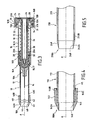
- la
figure 1 est une vue en coupe d'un ensemble d'un dispositif de support de sécurité et d'une seringue en position escamotée d'attente, - la
figure 2A est une vue partielle en perspective prise selon la direction II indiquée sur lafigure 1 , - la
figure 2B est une coupe partielle selon les flèches IIB-IIB de lafigure 1 , - la
figure 3 est une vue en coupe de l'ensemble de lafigure 1 en position active de protection, - la
figure 4 est une vue partielle en coupe de la partie avant du fourreau intérieur selon un autre mode de réalisation, et - la
figure 5 est une vue partielle en coupe de la partie avant du fourreau intérieur selon un autre mode de réalisation.
- the
figure 1 is a sectional view of an assembly of a safety support device and a syringe in the retracted position of waiting, - the
Figure 2A is a partial perspective view taken along the direction II indicated on thefigure 1 , - the
Figure 2B is a partial section along arrows IIB-IIB of thefigure 1 , - the
figure 3 is a sectional view of the whole of thefigure 1 in active protection position, - the
figure 4 is a partial sectional view of the front part of the inner sleeve according to another embodiment, and - the
figure 5 is a partial sectional view of the front portion of the inner sleeve according to another embodiment.
La seringue représentée sur les
Le dispositif de support de sécurité pour cette seringue comporte un fourreau extérieur de support 16 et un fourreau intérieur 18 qui peut coulisser entre une position escamotée d'attente avant injection, représentée sur la
Ces extrémités avant 16A et 18A sont bien entendu celles qui sont les plus proches du point d'injection, le sens vers l'avant étant le sens F de poussée du piston 12 dans le corps de seringue 10 pendant l'injection.These
Le corps de seringue 10 est calé fixement par rapport au fourreau de support 16 par des moyens de calage appartenant à ce fourreau 16 et coopérant avec une collerette radiale 20 que présente l'extrémité arrière 10B du corps de seringue 10 (extrémité opposée à l'aiguille 14). La collerette 20 se trouve alors calée entre une butée comprenant en l'espèce deux épaulements 22B réalisés chacun à partir d'une portion de paroi axiale 22 rigides et des pattes d'encliquetage 24 ménagées à l'intérieur de ce fourreau de support 16 (par exemple, quatre pattes régulièrement réparties sur la périphérie interne de ce dernier). Ces deux portions de paroi axiale 22 sont diamétralement opposées sur le fourreau de support 16.The
Lors de la mise en place du corps de seringue 10 dans le dispositif de support de sécurité, les pattes d'encliquetage 24, formées en arrière des épaulements 22B, s'écartent élastiquement pour permettre le passage de la collerette 20 du corps de seringue 10. Ainsi disposée, la collerette 20 est bien calée entre les épaulements 22B (dans le sens F de rentrée du piston) et les pattes d'encliquetage 24 (dans le sens opposé), de sorte que le corps de seringue 10 est maintenu fixement dans le fourreau de support 16 tout au long de l'injection et même pendant la sortie automatique en position active de protection du fourreau intérieur 18.When placing the
Comme on le voit plus en détails sur la
Dans la configuration active de retenue, les languettes de retenue 28 et 30 du fourreau intérieur 18 retiennent ce dernier en position escamotée d'attente dans le fourreau de support 16. On pourrait, bien entendu, imaginer que ces languettes soient plutôt formées à la périphérie interne du fourreau extérieur 16 s'accrochant alors sur le fourreau intérieur 18 ou bien que ces languettes élastiques aient un sens d'accrochage inversé par rapport à celui que montre la
Les extrémités libres respectives 28A et 30A des languettes de retenue 28 et 30 du fourreau intérieur 16 viennent en regard de languettes d'activation 29 et 31 élastiques formées axialement sur le fourreau de support 16 qui sont susceptibles d'être sollicitées vers une configuration inactive dans lesquelles elles autorisent la sortie du fourreau intérieur 18 hors du fourreau de support 16. En l'espèce, ces languettes d'activation 29 et 31 peuvent être sollicitées par une partie de commande du piston 12.The respective
Dans l'exemple représenté, la tête 13 du piston 12 présente cette partie de commande en forme de bride axiale 13A dirigée vers l'avant dont la périphérie interne 13B est inclinée, de telle sorte que, lorsque le piston 12 parvient en fin de course, cette périphérique interne 13B coopère avec les extrémités 29A et 31A des languettes d'activation 29 et 31, et sollicite ces dernières en les resserrant vers l'axe A. En se rapprochant de l'axe A, les languettes d'activation 29 et 31 sollicitent simultanément les portions d'extrémités 28A et 30A de sorte que languettes de retenue 28 et 30 se resserrent à leur tour vers l'axe A et libère leur épaulement 28B et 30B des surfaces de retenue respectives 32 et 34.In the example shown, the
En fait, chacune des languettes d'activation 29 et 31 est disposée entre deux des quatre pattes d'encliquetage 24, tandis que chacune des portions axiales 22 est disposée entre les deux autres pattes d'encliquetage 24, de sorte qu'il existe une alternance du type languette d'activation / patte / portion axiale / patte sur toute la périphérie du fourreau de support 16.In fact, each of the
Pour simplifier la réalisation du fourreau de support 16, ce dernier comporte comme dans l'exemple représenté, deux portions 16'A et 16'8, la portion 16'A étant de forme relativement simple, tandis que la portion 16'B à l'arrière du fourreau de support 16 plus complexe comporte l'ensemble de ces languettes 29, 31, de ces portions axiales 22 et de ces pattes 24. Les deux portions 16'A et 16'B sont maintenues l'une par rapport à l'autre par emmanchement ou tout autre moyen de coopération connu.To simplify the production of the
En fin de course du piston 12, le fourreau intérieur 18 se sépare du fourreau de support 16 par libération des languettes axiales de retenue 28 et 30 des surfaces de retenue respectives 32 et 34.At the end of stroke of the
Des moyens de poussée, en l'espèce un ressort 36, favorisent la poussée vers l'avant (dans le sens F indiqué sur la
Comme on le voit sur la
En fait, les deux portions de paroi axiale 22 portent chacune un secteur radial en saillie vers l'axe A des fourreaux 16 et 18, les faces avant de ces secteurs forment les faces frontales 22A, tandis que leur face arrière forme les épaulements 22B.In fact, the two
Le fourreau intérieur 18 présente en outre une portion tubulaire 19 formée entre l'épaulement 17 et les languettes de retenue 28 et 30 qui s'étendent vers l'arrière du fourreau intérieur 18. Cette portion tubulaire présente un diamètre augmenté par rapport au diamètre du fourreau intérieur 18 et permet d'éviter le contact entre le ressort 36 et les languettes de retenue 28 et 30 et donc tout risque d'endommagement de ces dernières, par frottement par exemple.The
L'espace annulaire ménagé pour le ressort 36 est donc limité par la surface d'appui formée par les faces frontales 22A, par l'épaulement 17, par la portion 19 tubulaire, et par les languettes de retenue 28 et 30. En position escamotée d'attente, le ressort 36 est ainsi maintenu précontraint entre ses surfaces d'appui formées d'une part, par les faces frontales 22A et d'autre part, par l'épaulement 17.The annular space provided for the
Après utilisation de la seringue, et en particulier en fin d'injection, comme illustré sur les
Le fourreau intérieur 18 n'étant plus retenu par les languettes de retenue 28 et 30 dans le fourreau de support 16, le ressort 36 a poussé le fourreau intérieur 18 vers l'avant de telle sorte que ce dernier dépasse largement au-delà de l'extrémité avant 16A du fourreau de support 16, sur une longueur telle qu'il forme une protection autour de l'aiguille 14 sur une longueur suffisante pour éviter les risques de contact d'un utilisateur avec l'aiguille 14.As the
Dans cette position active de protection, le fourreau intérieur 18 est calé vers l'avant par la venue en butée de son épaulement 17 avec un épaulement 15 formé intérieurement dans une région avant du fourreau extérieur 16. Des moyens de blocage permettent de bloquer le fourreau intérieur 18 dans cette position active de protection. Ces moyens de blocage permettent d'éviter qu'un simple appui sur l'extrémité libre 18A du fourreau intérieur 18 ne permette la rentrée de ce fourreau 18 dans le fourreau extérieur 16, auquel cas l'aiguille 14 pourrait devenir accessible par l'utilisateur.In this active protective position, the
Ces moyens de blocage comprennent en l'espèce un épaulement 38 formé dans le fourreau de support 16 et orienté à l'opposé de l'épaulement 15. Les extrémités libres 28A et 30A respectives des languettes axiales de retenue 28 et 30 sont aptes à coopérer avec cet épaulement 38 de sorte que le fourreau intérieur 18 se trouve calé entre le premier épaulement 15 l'empêchant d'aller vers l'avant dans le sens F, et le deuxième épaulement 38 l'empêchant de revenir vers l'arrière du dispositif de support de sécurité à l'opposé du déplacement de sortie du fourreau intérieur 18.These locking means comprise in this case a
Le ressort 36 étant calé entre la face frontale 20A et l'épaulement 17, le dispositif de support de sécurité peut être livré préarmé avec ou sans seringue. La seringue est alors simplement mise en place dans le dispositif de support de sécurité par simple encliquetage de sa collerette 20 et calage de cette dernière entre les épaulements 22B et les pattes d'encliquetage 24 du fourreau de support 16.With the
Lorsqu'une seringue est mise en place dans le dispositif de support de sécurité, l'utilisateur manipule l'ensemble constitué par ce dispositif et par cette seringue en tenant le fourreau de support 16, par exemple entre l'index et le majeur, en les calant par exemple sur une collerette 16B formée à l'extrémité arrière de ce fourreau de support 16, et en manipulant le piston 12 par exemple avec le pouce.When a syringe is placed in the safety support device, the user manipulates the assembly constituted by this device and by this syringe while holding the
La sortie du fourreau intérieur 18 se fait de manière automatique, sans intervention supplémentaire de l'utilisateur dès que le piston 12 atteint sa fin de course. Le choix de la raideur du ressort 36 permet de réguler cette sortie du fourreau intérieur 18 hors du fourreau de support et de limiter l'appui contre la chair du patient.The output of the
En outre, pour amortir l'appui dû à la percussion du fourreau intérieur 18 contre la peau du patient, le fourreau intérieur 18 comporte sur sa partie avant un embout 40 souple. L'extrémité libre de cet embout 40 forme l'extrémité libre 18A du fourreau intérieur 18.In addition, to dampen the support due to the percussion of the
Dans l'exemple représenté, le fourreau intérieur 18 est formé par deux parties de rigidité différentes : une première partie rigide 19 par laquelle le fourreau intérieur 18 coopère avec le fourreau de support 16, et une deuxième partie formée par l'embout 40 souple solidaire de la première partie 19.In the example shown, the
Classiquement, le fourreau de support 16 et le fourreau intérieur 18 sont tubulaires et réalisés en plastique. Dans l'exemple représenté, l'intégralité de la première partie 19 est rigide, mais le fourreau intérieur 18 pourrait présenter des parties plus ou moins souples comportant des zones rigides qui lui permettent de coulisser sans se déformer dans le fourreau de support 16 et ainsi d'éviter tout risque d'arc-boutement dans ce dernier. Ces zones rigides pourraient, par exemple, être formées par des pattes rectilignes longitudinales qui s'étendraient le long de la première partie 19 du fourreau intérieur 18.Conventionally, the
La deuxième partie du fourreau de support formé par l'embout 40 étant quant à elle destinée à amortir l'appui lors de la sortie du fourreau intérieur 18, elle est préférentiellement formée par un matériau plastique choisi parmi le PVC, les polyéthylènes, les élastomères ou le caoutchouc. Le matériau formant l'embout 40 présente avantageusement une dureté Shore comprise entre 30 Hs et 80 Hs, préférentiellement comprise entre 40 Hs et 50 Hs, pour assurer un bon amortissement, même en cas de sortie violente du fourreau intérieur 18, par exemple causé par une défaillance des moyens de retenue.The second part of the support sleeve formed by the
En outre, dans l'exemple représenté, l'embout 40 présente une épaisseur plus fine vers l'avant. En l'espèce, l'embout 40 présente une première partie 40B sensiblement tubulaire et une partie avant 40A sensiblement tronconique dont l'extrémité la plus fine est tournée vers l'avant du dispositif de sécurité.In addition, in the example shown, the
Avec une telle conformation de l'embout 40, lors de la sortie du fourreau intérieur 18 hors du fourreau de support 16 et de l'arrivée du fourreau intérieur 18 contre la chair du patient, au moins une partie de l'énergie accumulée par le ressort 36 qui n'aurait pas été libérée par le déplacement du fourreau intérieur 18 dans le fourreau de support 16 serait encaissée par la déformation de l'embout 40.With such a conformation of the
Selon un premier mode de réalisation, illustré sur la
Sur l'exemple représenté sur la
On pourrait également imaginer que les bourrelets 42 soient formés sur la première partie 19 du fourreau intérieur 18 et que l'embout 40 présente des encoches 44 destinées à coopérer avec ces bourrelets 42 ou que cette première partie 19 et l'embout 40 présentent chacun un bourrelet et une encoche, le bourrelet de l'un coopérant avec l'encoche de l'autre. Dans ce mode de réalisation, toutes les formes possibles de l'organe en saillie et de l'organe en retrait permettant une coopération de l'embout 40 sur la première partie 19 du fourreau intérieur 18 peuvent être envisagées.One could also imagine that the
Selon un autre mode de réalisation, l'embout 140 est fixé à la première partie 119 du fourreau intérieur 118, par simple emmanchement en force de l'embout 140 sur l'extrémité libre de la première partie 119, comme illustré sur la
Cet embout 140 peut en outre être fixé à la première partie 119 du fourreau intérieur 118 par des moyens 45, choisis parmi le collage, le surmoulage ou le soudage pour assurer son maintien en position.This
Dans ce mode de réalisation, l'embout 140 se présente extérieurement de la même manière que l'embout 40 précédemment décrit, avec une partie tronconique 140A identique. De par l'absence de bourrelets, l'intérieur de la partie 140B est simplifiée en une forme cylindrique de diamètre intérieur correspondant au diamètre extérieur de la première partie 119 du fourreau intérieur 118, qui se prolonge jusqu'à l'épaulement 141. Le remplissage de l'ouverture évasée 140C (à l'opposée de l'avant 118A) par un adhésif 45 permet un bon maintien de l'embout 140 sur la première partie 119 du fourreau intérieur 118.In this embodiment, the
Selon un autre mode de réalisation illustré sur la
Quelle que soit la variante envisagée, l'embout doit être suffisamment souple pour amortir les appuis lors de la percussion du fourreau intérieur contre la chair du patient, mais il est préférable d'éviter, pour des raisons d'hygiène, que l'embout puisse venir en contact avec une partie de l'aiguille. La déformation de l'embout ne doit pas pouvoir permettre à ce dernier de toucher l'aiguille, même lorsqu'une pression importante, due par exemple à un écrasement de l'embout, est exercée sur ce dernier. On pourra par exemple, selon la dureté du matériau, être amené à positionner l'extrémité libre de l'embout au ras de l'extrémité du corps de seringue proche de l'aiguille, en position escamotée d'attente.Whatever the variant envisaged, the tip must be flexible enough to dampen the supports during the percussion of the inner sleeve against the flesh of the patient, but it is preferable to avoid, for reasons of hygiene, that the tip can come in contact with a part of the needle. The deformation of the tip must not be able to allow the latter to touch the needle, even when a significant pressure, due for example to a crushing of the tip, is exerted on the latter. For example, depending on the hardness of the material, it may be necessary to position the free end of the tip flush with the end of the syringe body close to the needle, in retracted position waiting.
L'ensemble formé par le dispositif de support de sécurité et par la seringue comporte en outre un capuchon amovible qui protège l'aiguille avant utilisation et en particulier lorsque le fourreau intérieur 18 est en position escamotée d'attente. Ce capuchon protège l'aiguille 14 de la seringue et coopère avec le corps de seringue 18 sur sa partie avant 10A. En l'espèce, le capuchon 46 représenté sur la
Dans la position escamotée d'attente du fourreau intérieur 18, l'embout 40 entoure sensiblement sans jeu le capuchon 46 de manière à protéger la seringue et l'aiguille 14 de toute contamination extérieure par liaison sensiblement étanche. En l'espèce, l'embout 40 présente un contour intérieur 48 de géométrie sensiblement identique à celle du contour extérieur du capuchon 46. Le capuchon 46 est fréquemment de forme tronconique évasée vers son ouverture, de sorte qu'il suffit de choisir un contour intérieur 48 de l'embout 40 de diamètre sensiblement égal au diamètre moyen du contour extérieur 40 du capuchon 46. Ainsi, l'embout 40 vient coopérer avec le capuchon 46 par légère déformation sur de l'embout 40 qui épouse le contour du capuchon 46. Le capuchon 46 amovible est retiré par l'utilisateur avant injection, en tirant simplement le capuchon 46 avec une main par exemple, tandis que l'autre main de l'utilisateur retient le dispositif de support de sécurité.In the retracted retracted position of the
Claims (11)
caractérisé en ce qu'il comporte aussi :
characterized in that it also comprises:
caractérisé en ce qu'il comporte aussi :
characterized in that it also comprises:
caractérisé en ce qu'il comporte aussi :
characterized in that it also comprises:
Priority Applications (2)
| Application Number | Priority Date | Filing Date | Title |
|---|---|---|---|
| SI200332384T SI2308532T1 (en) | 2002-02-11 | 2003-02-11 | Security support device for a syringe and assambly of such a device and a syringe |
| CY20141100715T CY1115753T1 (en) | 2002-02-11 | 2014-09-05 | SUPPORTING SAFETY DEVICE FOR A SYNERGY AND TOTAL OF AN EFFECTIVE DEVICE AND A SYNERGY |
Applications Claiming Priority (2)
| Application Number | Priority Date | Filing Date | Title |
|---|---|---|---|
| FR0201643A FR2835753B1 (en) | 2002-02-11 | 2002-02-11 | SAFETY SUPPORT DEVICE FOR A SYRINGE AND ASSEMBLY OF SUCH A DEVICE AND A SYRINGE |
| EP03739519A EP1474194B1 (en) | 2002-02-11 | 2003-02-11 | Safety support device for a syringe and an assembly comprising one such device and a syringe |
Related Parent Applications (4)
| Application Number | Title | Priority Date | Filing Date |
|---|---|---|---|
| EP03739519A Division EP1474194B1 (en) | 2002-02-11 | 2003-02-11 | Safety support device for a syringe and an assembly comprising one such device and a syringe |
| PCT/FR2003/000423 Previously-Filed-Application WO2003068298A1 (en) | 2002-02-11 | 2003-02-11 | Safety support device for a syringe and an assembly comprising one such device and a syringe |
| EP03739519.1 Division | 2003-02-11 | ||
| WOPCT/FR03/00423 Previously-Filed-Application | 2003-02-11 |
Publications (2)
| Publication Number | Publication Date |
|---|---|
| EP2308532A1 true EP2308532A1 (en) | 2011-04-13 |
| EP2308532B1 EP2308532B1 (en) | 2014-06-11 |
Family
ID=27620081
Family Applications (2)
| Application Number | Title | Priority Date | Filing Date |
|---|---|---|---|
| EP10184229.2A Expired - Lifetime EP2308532B1 (en) | 2002-02-11 | 2003-02-11 | Security support device for a syringe and assambly of such a device and a syringe |
| EP03739519A Expired - Lifetime EP1474194B1 (en) | 2002-02-11 | 2003-02-11 | Safety support device for a syringe and an assembly comprising one such device and a syringe |
Family Applications After (1)
| Application Number | Title | Priority Date | Filing Date |
|---|---|---|---|
| EP03739519A Expired - Lifetime EP1474194B1 (en) | 2002-02-11 | 2003-02-11 | Safety support device for a syringe and an assembly comprising one such device and a syringe |
Country Status (13)
| Country | Link |
|---|---|
| US (7) | US7850661B2 (en) |
| EP (2) | EP2308532B1 (en) |
| JP (1) | JP4314117B2 (en) |
| AT (1) | ATE505226T1 (en) |
| AU (1) | AU2003226872A1 (en) |
| CY (2) | CY1111686T1 (en) |
| DE (1) | DE60336706D1 (en) |
| DK (2) | DK2308532T3 (en) |
| ES (2) | ES2364841T3 (en) |
| FR (1) | FR2835753B1 (en) |
| PT (2) | PT2308532E (en) |
| SI (2) | SI2308532T1 (en) |
| WO (1) | WO2003068298A1 (en) |
Cited By (1)
| Publication number | Priority date | Publication date | Assignee | Title |
|---|---|---|---|---|
| USD765838S1 (en) | 2015-03-26 | 2016-09-06 | Tech Group Europe Limited | Syringe retention clip |
Families Citing this family (44)
| Publication number | Priority date | Publication date | Assignee | Title |
|---|---|---|---|---|
| FR2801795B1 (en) * | 1999-12-07 | 2002-07-05 | Plastef Investissements | SAFETY SUPPORT DEVICE FOR A SYRINGE AND ASSEMBLY OF SUCH A DEVICE AND A SYRINGE |
| FR2835753B1 (en) | 2002-02-11 | 2004-10-29 | Plastef Investissements | SAFETY SUPPORT DEVICE FOR A SYRINGE AND ASSEMBLY OF SUCH A DEVICE AND A SYRINGE |
| US6776777B2 (en) | 2002-05-10 | 2004-08-17 | Becton, Dickinson And Company | Passive safety shield system for injection devices |
| US8932265B2 (en) | 2003-01-30 | 2015-01-13 | Becton, Dickinson And Company | Holder with safety shield for a drug delivery device |
| FR2852851B1 (en) | 2003-03-25 | 2006-01-06 | Sedat | NEEDLE PROTECTION DEVICE FOR SYRINGE, AND INJECTION DEVICE COMPRISING SYRINGE AND PROTECTIVE DEVICE |
| FR2860162B1 (en) * | 2003-09-26 | 2006-06-02 | Becton Dickinson France | DEVICE FOR PROTECTING AN INJECTION APPARATUS |
| FR2861310B1 (en) * | 2003-10-22 | 2006-09-22 | Plastef Investissements | SECURE INJECTION SYRINGE DEVICE |
| FR2861598B1 (en) | 2003-10-29 | 2006-06-16 | Plastef Investissements | SECURE INJECTION DEVICE FOR A SYRINGE |
| JP4874972B2 (en) * | 2004-08-27 | 2012-02-15 | セダ | Needle protection device and injection device having the same |
| FR2874506B1 (en) * | 2004-08-27 | 2007-06-08 | Sedat Sa | NEEDLE PROTECTION DEVICE FOR SYRINGE AND INJECTION DEVICE COMPRISING SAME |
| US8062252B2 (en) | 2005-02-18 | 2011-11-22 | Becton, Dickinson And Company | Safety shield system for a syringe |
| US20070078403A1 (en) * | 2005-08-25 | 2007-04-05 | Don Millerd | Syringe guard for pre-filled medicament vial |
| DE102005043805A1 (en) * | 2005-09-14 | 2007-03-22 | Tecpharma Licensing Ag | Positioning device for e.g. injecting pen, has needle guide/cover with positioning unit to guide or position needle, or protective caps or needle holder, so that needle is guided and/or positioned relative to preset entry position by unit |
| US20090270803A1 (en) * | 2006-06-16 | 2009-10-29 | Marc Brunel | Safety device for injecting a medicinal product, such as a lyophilized product |
| FR2905873B1 (en) | 2006-09-20 | 2008-11-14 | Becton Dickinson France Soc Pa | INJECTION DEVICE PREVENTING PISTON RELEASE DURING DEPLOYMENT OF THE SAFETY SYSTEM |
| FR2922456B1 (en) | 2007-10-23 | 2009-12-11 | Plastef Investissements | SAFETY DEVICE FOR A SYRINGE. |
| FR2922455B1 (en) | 2007-10-23 | 2010-10-29 | Plastef Investissements | SYRINGE DEVICE COMPRISING A SYRINGE BODY AND A SUPPORT SLEEVE. |
| FR2922457B1 (en) | 2007-10-23 | 2010-10-29 | Plastef Investissements | SYRINGE DEVICE WITH PROTECTIVE CAP. |
| ATE554814T1 (en) * | 2008-02-15 | 2012-05-15 | Becton Dickinson Co | SAFETY PIN ARRANGEMENT |
| WO2010128350A1 (en) * | 2009-05-07 | 2010-11-11 | Becton Dickinson France | Supporting sleeve for a container with a flange |
| US8920385B2 (en) | 2010-05-05 | 2014-12-30 | Safety Syringes, Inc. | Extended finger flange for syringe systems |
| CN103079611B (en) * | 2010-07-02 | 2016-06-15 | 赛诺菲-安万特德国有限公司 | For the needle housings of safety device, safety device and injection device |
| JP2012152443A (en) * | 2011-01-27 | 2012-08-16 | Arte Corp | Combined container-syringe |
| WO2012138318A1 (en) | 2011-04-04 | 2012-10-11 | West Pharmaceutical Services, Inc. | Needle safety shield |
| CA2854003C (en) * | 2011-11-07 | 2020-07-14 | Safety Syringes, Inc. | Contact trigger release needle guard |
| US9623193B2 (en) * | 2011-12-06 | 2017-04-18 | Robert J. Cohn | Syringe assembly with automatic safety shield |
| JP6360038B2 (en) | 2012-05-04 | 2018-07-18 | サノフィ−アベンティス・ドイチュラント・ゲゼルシャフト・ミット・ベシュレンクテル・ハフツング | Drug delivery device |
| US9050416B2 (en) | 2012-11-01 | 2015-06-09 | Tech Group Europe Limited | Needle Safety device with floating ring |
| DE102013214442A1 (en) * | 2013-07-24 | 2015-01-29 | Raumedic Ag | Medical injection device |
| DE102013214429A1 (en) * | 2013-07-24 | 2015-02-19 | Raumedic Ag | Medical injection device |
| DK3335751T3 (en) * | 2013-08-29 | 2021-03-22 | Sanofi Sa | SAFETY DEVICE FOR A MEDICINE CONTAINER |
| DE202014004561U1 (en) | 2014-06-03 | 2014-07-03 | H & B Electronic Gmbh & Co. Kg | injection device |
| FR3031904B1 (en) * | 2015-01-26 | 2021-08-27 | Biocorp Rech Et Developpement | DEVICE FOR PROTECTING A NEEDLE, SYRINGE EQUIPPED WITH SUCH A DEVICE AND METHOD FOR MANUFACTURING PRE-FILLED SYRINGES WITH A GLUED NEEDLE |
| ES2732714T3 (en) * | 2015-01-26 | 2019-11-25 | Biocorp Prod | Needle protection device, syringe equipped with such device and manufacturing procedure for pre-filled syringes with attached needle |
| EP4252798A3 (en) | 2015-06-04 | 2023-10-25 | Medimop Medical Projects Ltd. | Cartridge insertion for drug delivery device |
| FR3038840B1 (en) * | 2015-07-16 | 2017-07-21 | Nemera La Verpilliere | SAFETY DEVICE FOR INJECTION SYRINGE. |
| CN114470420A (en) | 2017-12-22 | 2022-05-13 | 西氏医药包装(以色列)有限公司 | Syringe adapted for cartridges of different sizes |
| MX2020009431A (en) | 2018-03-13 | 2021-03-09 | Mylan Uk Healthcare Ltd | Devices for injecting medicaments and methods of use. |
| CN111770770B (en) * | 2018-03-19 | 2022-08-23 | 贝克顿迪金森法国公司 | Housing for receiving an injection system comprising a syringe accommodated in a safety device |
| US10675416B2 (en) * | 2018-08-17 | 2020-06-09 | David Harold Kovacs | Retractable syringe |
| WO2021078605A1 (en) * | 2019-10-23 | 2021-04-29 | Becton Dickinson France | Injection device |
| JP1691373S (en) | 2019-11-01 | 2021-08-02 | ||
| USD948715S1 (en) * | 2020-11-06 | 2022-04-12 | West Pharmaceutical Services, Inc. | Injection needle shield puller |
| WO2023161429A1 (en) | 2022-02-24 | 2023-08-31 | Roncadelle Operations Srl | Syringe assembly with automatic safety sleeve |
Citations (3)
| Publication number | Priority date | Publication date | Assignee | Title |
|---|---|---|---|---|
| FR2801795A1 (en) | 1999-12-07 | 2001-06-08 | Plastef Investissements | SAFETY SUPPORT DEVICE FOR A SYRINGE AND ASSEMBLY OF SUCH A DEVICE AND A SYRINGE |
| WO2001085239A2 (en) * | 2000-05-05 | 2001-11-15 | Safety Syringes, Inc. | Passive needle guard for syringes |
| US6319234B1 (en) * | 1997-02-12 | 2001-11-20 | Sergio Restelli | Disposable safety syringe |
Family Cites Families (28)
| Publication number | Priority date | Publication date | Assignee | Title |
|---|---|---|---|---|
| US2674246A (en) * | 1952-03-14 | 1954-04-06 | Earl J Bower | Hypodermic syringe |
| US4775369A (en) * | 1986-09-09 | 1988-10-04 | Boris Schwartz | Automatically actionable sharpened needle-tip protection |
| US4927416A (en) | 1987-12-02 | 1990-05-22 | National Medical Device Corporation | User-protective hypodermic syringe holder |
| US4898589A (en) * | 1988-03-09 | 1990-02-06 | Stuart M. Dolgin | Fluid passing apparatus with means for covering the same |
| US5156599A (en) * | 1988-06-28 | 1992-10-20 | Sherwood Medical Company | Syringe and sliding locking needle shield |
| FR2648716B1 (en) | 1989-06-27 | 1991-09-13 | Guerineau Jean | SINGLE USE SYRINGE. SELF-CONTAINING SYRINGE-NEEDLE COMBINATION IN A PROTECTIVE SLEEVE |
| FR2654346A1 (en) | 1989-11-10 | 1991-05-17 | Laisne Maurice | Syringe which can be used only once and which has an incorporated and sliding system for protecting the needle |
| EP0467173B1 (en) * | 1990-07-19 | 1995-11-08 | Nardino Righi | Disposable safety syringe |
| US5242416A (en) * | 1992-01-09 | 1993-09-07 | Hutson Clifford L | Shield assembly for needle syringes |
| US5492536A (en) * | 1992-01-21 | 1996-02-20 | Mascia; Michael F. | Safely disposable syringe |
| US5201720A (en) | 1992-04-21 | 1993-04-13 | Joseph Borgia | Syringe holding and ejecting assembly |
| US5342320A (en) * | 1993-01-15 | 1994-08-30 | Cameron Robert W | Hypodermic syringe having shielding to prevent accidental injury following use |
| EP0680767A1 (en) | 1994-05-06 | 1995-11-08 | Nardino Righi | Non-reusable safety syringe |
| US5746718A (en) * | 1994-07-05 | 1998-05-05 | Steyn; Ricardo Sheath Oxford | Needle protective device |
| FR2736553B1 (en) * | 1995-07-12 | 1998-01-09 | Soc Et Et D Applic Tech Sedat | INJECTION SYRINGE, IN PARTICULAR LIQUID MEDICAL PRODUCTS, WITH MOBILE NEEDLE PROTECTOR |
| US5591138A (en) * | 1995-08-10 | 1997-01-07 | Vaillancourt; Vincent L. | Protected needle assembly |
| US5562626A (en) | 1995-09-11 | 1996-10-08 | Sanpietro; Joseph A. | Safety syringe |
| US6159184A (en) | 1997-03-10 | 2000-12-12 | Safety Syringes, Inc. | Disposable self-shielding unit dose syringe guard |
| US6171283B1 (en) | 1997-03-10 | 2001-01-09 | Safety Syringes, Inc. | Disposable self-shielding unit dose syringe guard |
| US6319233B1 (en) | 1998-04-17 | 2001-11-20 | Becton, Dickinson And Company | Safety shield system for prefilled syringes |
| US6679864B2 (en) * | 1998-04-17 | 2004-01-20 | Becton Dickinson And Company | Safety shield system for prefilled syringes |
| FR2778853B1 (en) | 1998-05-19 | 2000-12-22 | Sedat | INJECTION SYRINGE WITH SPRING LOADED NEEDLE PROTECTOR |
| FR2799376B1 (en) | 1999-10-07 | 2002-01-18 | Marc Brunel | SINGLE USE INJECTION DEVICE |
| FR2802103B1 (en) * | 1999-12-08 | 2003-10-03 | Poudres & Explosifs Ste Nale | SYRINGE WITHOUT NEEDLE OPERATING WITH DRIVE OF THE ACTIVE PRINCIPLE BY IMPACT TUBE |
| US6623459B1 (en) * | 2000-05-05 | 2003-09-23 | Safety Syringes, Inc. | Passive needle guard for syringes |
| US6648858B2 (en) * | 2001-12-21 | 2003-11-18 | Visual Connections, Inc. | Safety device for a sheathed, prefilled injection syringe |
| FR2835753B1 (en) | 2002-02-11 | 2004-10-29 | Plastef Investissements | SAFETY SUPPORT DEVICE FOR A SYRINGE AND ASSEMBLY OF SUCH A DEVICE AND A SYRINGE |
| US6776777B2 (en) * | 2002-05-10 | 2004-08-17 | Becton, Dickinson And Company | Passive safety shield system for injection devices |
-
2002
- 2002-02-11 FR FR0201643A patent/FR2835753B1/en not_active Expired - Fee Related
-
2003
- 2003-02-11 ES ES03739519T patent/ES2364841T3/en not_active Expired - Lifetime
- 2003-02-11 PT PT101842292T patent/PT2308532E/en unknown
- 2003-02-11 AU AU2003226872A patent/AU2003226872A1/en not_active Abandoned
- 2003-02-11 AT AT03739519T patent/ATE505226T1/en active
- 2003-02-11 PT PT03739519T patent/PT1474194E/en unknown
- 2003-02-11 SI SI200332384T patent/SI2308532T1/en unknown
- 2003-02-11 DE DE60336706T patent/DE60336706D1/en not_active Expired - Lifetime
- 2003-02-11 DK DK10184229.2T patent/DK2308532T3/en active
- 2003-02-11 WO PCT/FR2003/000423 patent/WO2003068298A1/en active Application Filing
- 2003-02-11 EP EP10184229.2A patent/EP2308532B1/en not_active Expired - Lifetime
- 2003-02-11 SI SI200332017T patent/SI1474194T1/en unknown
- 2003-02-11 DK DK03739519.1T patent/DK1474194T3/en active
- 2003-02-11 EP EP03739519A patent/EP1474194B1/en not_active Expired - Lifetime
- 2003-02-11 JP JP2003567478A patent/JP4314117B2/en not_active Expired - Fee Related
- 2003-02-11 ES ES10184229.2T patent/ES2500646T3/en not_active Expired - Lifetime
- 2003-02-11 US US10/503,229 patent/US7850661B2/en not_active Expired - Lifetime
-
2008
- 2008-06-26 US US12/215,483 patent/US20080294120A1/en not_active Abandoned
-
2010
- 2010-10-12 US US12/902,655 patent/US8308696B2/en active Active
-
2011
- 2011-07-13 CY CY20111100679T patent/CY1111686T1/en unknown
-
2012
- 2012-10-09 US US13/647,928 patent/US8603043B2/en active Active
-
2013
- 2013-10-02 US US14/044,081 patent/US9555196B2/en not_active Expired - Lifetime
-
2014
- 2014-09-05 CY CY20141100715T patent/CY1115753T1/en unknown
-
2017
- 2017-01-30 US US15/419,584 patent/US11135377B2/en not_active Expired - Lifetime
-
2021
- 2021-08-13 US US17/402,139 patent/US20210369976A1/en not_active Abandoned
Patent Citations (3)
| Publication number | Priority date | Publication date | Assignee | Title |
|---|---|---|---|---|
| US6319234B1 (en) * | 1997-02-12 | 2001-11-20 | Sergio Restelli | Disposable safety syringe |
| FR2801795A1 (en) | 1999-12-07 | 2001-06-08 | Plastef Investissements | SAFETY SUPPORT DEVICE FOR A SYRINGE AND ASSEMBLY OF SUCH A DEVICE AND A SYRINGE |
| WO2001085239A2 (en) * | 2000-05-05 | 2001-11-15 | Safety Syringes, Inc. | Passive needle guard for syringes |
Cited By (1)
| Publication number | Priority date | Publication date | Assignee | Title |
|---|---|---|---|---|
| USD765838S1 (en) | 2015-03-26 | 2016-09-06 | Tech Group Europe Limited | Syringe retention clip |
Also Published As
| Publication number | Publication date |
|---|---|
| PT2308532E (en) | 2014-09-12 |
| US7850661B2 (en) | 2010-12-14 |
| JP2005516741A (en) | 2005-06-09 |
| US11135377B2 (en) | 2021-10-05 |
| US9555196B2 (en) | 2017-01-31 |
| US20170203048A1 (en) | 2017-07-20 |
| EP2308532B1 (en) | 2014-06-11 |
| DE60336706D1 (en) | 2011-05-26 |
| US20210369976A1 (en) | 2021-12-02 |
| ES2500646T3 (en) | 2014-09-30 |
| SI1474194T1 (en) | 2011-10-28 |
| FR2835753B1 (en) | 2004-10-29 |
| AU2003226872A1 (en) | 2003-09-04 |
| EP1474194A1 (en) | 2004-11-10 |
| US8603043B2 (en) | 2013-12-10 |
| ATE505226T1 (en) | 2011-04-15 |
| WO2003068298A1 (en) | 2003-08-21 |
| SI2308532T1 (en) | 2014-10-30 |
| EP1474194B1 (en) | 2011-04-13 |
| FR2835753A1 (en) | 2003-08-15 |
| US20110046605A1 (en) | 2011-02-24 |
| DK1474194T3 (en) | 2011-08-01 |
| JP4314117B2 (en) | 2009-08-12 |
| US20080294120A1 (en) | 2008-11-27 |
| ES2364841T3 (en) | 2011-09-15 |
| US20140031762A1 (en) | 2014-01-30 |
| US20130030377A1 (en) | 2013-01-31 |
| US20050148943A1 (en) | 2005-07-07 |
| US8308696B2 (en) | 2012-11-13 |
| CY1111686T1 (en) | 2015-10-07 |
| DK2308532T3 (en) | 2014-09-22 |
| PT1474194E (en) | 2011-07-14 |
| CY1115753T1 (en) | 2017-01-25 |
Similar Documents
| Publication | Publication Date | Title |
|---|---|---|
| EP1474194B1 (en) | Safety support device for a syringe and an assembly comprising one such device and a syringe | |
| EP2047879B1 (en) | Safety assembly for an injection syringe | |
| EP1781359B1 (en) | Syringe needle protective device and injecting device provided therewith | |
| EP1235603B1 (en) | Safety system for a syringe | |
| EP1027902B1 (en) | Autoprotected injection syringe | |
| EP1485153B1 (en) | Needle protection device for a syringe and an injection device comprising a syringe and said protection device | |
| EP0954345B1 (en) | Injection syringe with movable needle protector | |
| EP1532997B1 (en) | Needle protecting device for a carpule | |
| FR2481103A1 (en) | MEDICAL BISTOURI FOR COLLECTING A BLOOD DROP AND METHOD FOR MANUFACTURING THE SAME | |
| WO2011157930A1 (en) | Syringe and safety device assembly | |
| EP1330279A1 (en) | Injection syringe with mobile needle guard | |
| EP3074064A1 (en) | Auto-injector | |
| EP1687051B1 (en) | Safety injection device for syringe | |
| EP1436027A1 (en) | Safety device for a syringe | |
| EP2135631B1 (en) | Security device for an injection device | |
| FR2622804A1 (en) | Non-reusable syringe | |
| EP0954347B1 (en) | Injection syringe with needle projecting in the syringe body | |
| EP3416707A1 (en) | Device for injecting a liquid product, having simplified assembly | |
| WO2020079012A1 (en) | Passive injection device with automatic securing means |
Legal Events
| Date | Code | Title | Description |
|---|---|---|---|
| PUAI | Public reference made under article 153(3) epc to a published international application that has entered the european phase |
Free format text: ORIGINAL CODE: 0009012 |
|
| AC | Divisional application: reference to earlier application |
Ref document number: 1474194 Country of ref document: EP Kind code of ref document: P |
|
| AK | Designated contracting states |
Kind code of ref document: A1 Designated state(s): AT BE BG CH CY CZ DE DK EE ES FI FR GB GR HU IE IT LI LU MC NL PT SE SI SK TR |
|
| RAP1 | Party data changed (applicant data changed or rights of an application transferred) |
Owner name: SANOFI |
|
| 17P | Request for examination filed |
Effective date: 20110919 |
|
| RAP1 | Party data changed (applicant data changed or rights of an application transferred) |
Owner name: SANOFI |
|
| RAP1 | Party data changed (applicant data changed or rights of an application transferred) |
Owner name: SANOFI |
|
| 17Q | First examination report despatched |
Effective date: 20120511 |
|
| RIC1 | Information provided on ipc code assigned before grant |
Ipc: A61M 5/50 20060101AFI20120927BHEP Ipc: A61M 5/31 20060101ALN20120927BHEP |
|
| RIC1 | Information provided on ipc code assigned before grant |
Ipc: A61M 5/50 20060101AFI20130619BHEP Ipc: A61M 5/31 20060101ALN20130619BHEP |
|
| GRAP | Despatch of communication of intention to grant a patent |
Free format text: ORIGINAL CODE: EPIDOSNIGR1 |
|
| INTG | Intention to grant announced |
Effective date: 20130902 |
|
| GRAS | Grant fee paid |
Free format text: ORIGINAL CODE: EPIDOSNIGR3 |
|
| GRAA | (expected) grant |
Free format text: ORIGINAL CODE: 0009210 |
|
| AC | Divisional application: reference to earlier application |
Ref document number: 1474194 Country of ref document: EP Kind code of ref document: P |
|
| AK | Designated contracting states |
Kind code of ref document: B1 Designated state(s): AT BE BG CH CY CZ DE DK EE ES FI FR GB GR HU IE IT LI LU MC NL PT SE SI SK TR |
|
| REG | Reference to a national code |
Ref country code: GB Ref legal event code: FG4D Free format text: NOT ENGLISH |
|
| REG | Reference to a national code |
Ref country code: CH Ref legal event code: EP |
|
| REG | Reference to a national code |
Ref country code: IE Ref legal event code: FG4D Free format text: LANGUAGE OF EP DOCUMENT: FRENCH |
|
| REG | Reference to a national code |
Ref country code: AT Ref legal event code: REF Ref document number: 671925 Country of ref document: AT Kind code of ref document: T Effective date: 20140715 |
|
| REG | Reference to a national code |
Ref country code: DE Ref legal event code: R096 Ref document number: 60346335 Country of ref document: DE Effective date: 20140724 |
|
| REG | Reference to a national code |
Ref country code: PT Ref legal event code: SC4A Free format text: AVAILABILITY OF NATIONAL TRANSLATION Effective date: 20140903 |
|
| REG | Reference to a national code |
Ref country code: CH Ref legal event code: NV Representative=s name: MICHELI AND CIE SA, CH |
|
| REG | Reference to a national code |
Ref country code: NL Ref legal event code: T3 |
|
| REG | Reference to a national code |
Ref country code: DK Ref legal event code: T3 Effective date: 20140917 |
|
| REG | Reference to a national code |
Ref country code: ES Ref legal event code: FG2A Ref document number: 2500646 Country of ref document: ES Kind code of ref document: T3 Effective date: 20140930 |
|
| REG | Reference to a national code |
Ref country code: SE Ref legal event code: TRGR |
|
| REG | Reference to a national code |
Ref country code: GR Ref legal event code: EP Ref document number: 20140401803 Country of ref document: GR Effective date: 20141017 |
|
| REG | Reference to a national code |
Ref country code: EE Ref legal event code: FG4A Ref document number: E009686 Country of ref document: EE Effective date: 20140908 |
|
| REG | Reference to a national code |
Ref country code: SK Ref legal event code: T3 Ref document number: E 17297 Country of ref document: SK |
|
| REG | Reference to a national code |
Ref country code: HU Ref legal event code: AG4A Ref document number: E021537 Country of ref document: HU |
|
| REG | Reference to a national code |
Ref country code: DE Ref legal event code: R097 Ref document number: 60346335 Country of ref document: DE |
|
| PLBE | No opposition filed within time limit |
Free format text: ORIGINAL CODE: 0009261 |
|
| STAA | Information on the status of an ep patent application or granted ep patent |
Free format text: STATUS: NO OPPOSITION FILED WITHIN TIME LIMIT |
|
| 26N | No opposition filed |
Effective date: 20150312 |
|
| REG | Reference to a national code |
Ref country code: DE Ref legal event code: R097 Ref document number: 60346335 Country of ref document: DE Effective date: 20150312 |
|
| REG | Reference to a national code |
Ref country code: FR Ref legal event code: PLFP Year of fee payment: 14 |
|
| REG | Reference to a national code |
Ref country code: FR Ref legal event code: PLFP Year of fee payment: 15 |
|
| REG | Reference to a national code |
Ref country code: DE Ref legal event code: R082 Ref document number: 60346335 Country of ref document: DE Representative=s name: CBDL PATENTANWAELTE, DE Ref country code: DE Ref legal event code: R081 Ref document number: 60346335 Country of ref document: DE Owner name: SANOFI, FR Free format text: FORMER OWNER: SANOFI, PARIS, FR |
|
| REG | Reference to a national code |
Ref country code: FR Ref legal event code: PLFP Year of fee payment: 16 |
|
| PGFP | Annual fee paid to national office [announced via postgrant information from national office to epo] |
Ref country code: SE Payment date: 20211210 Year of fee payment: 20 Ref country code: BG Payment date: 20211214 Year of fee payment: 20 Ref country code: IE Payment date: 20211209 Year of fee payment: 20 Ref country code: GB Payment date: 20211223 Year of fee payment: 20 Ref country code: FR Payment date: 20211217 Year of fee payment: 20 |
|
| PGFP | Annual fee paid to national office [announced via postgrant information from national office to epo] |
Ref country code: CH Payment date: 20211216 Year of fee payment: 20 |
|
| PGFP | Annual fee paid to national office [announced via postgrant information from national office to epo] |
Ref country code: NL Payment date: 20211216 Year of fee payment: 20 Ref country code: LU Payment date: 20220124 Year of fee payment: 20 |
|
| PGFP | Annual fee paid to national office [announced via postgrant information from national office to epo] |
Ref country code: HU Payment date: 20220131 Year of fee payment: 20 Ref country code: FI Payment date: 20220209 Year of fee payment: 20 Ref country code: DK Payment date: 20220209 Year of fee payment: 20 Ref country code: DE Payment date: 20211222 Year of fee payment: 20 Ref country code: AT Payment date: 20220125 Year of fee payment: 20 |
|
| PGFP | Annual fee paid to national office [announced via postgrant information from national office to epo] |
Ref country code: TR Payment date: 20220209 Year of fee payment: 20 Ref country code: SK Payment date: 20220113 Year of fee payment: 20 Ref country code: PT Payment date: 20220211 Year of fee payment: 20 Ref country code: MC Payment date: 20220128 Year of fee payment: 20 Ref country code: IT Payment date: 20220111 Year of fee payment: 20 Ref country code: GR Payment date: 20220120 Year of fee payment: 20 Ref country code: ES Payment date: 20220304 Year of fee payment: 20 Ref country code: EE Payment date: 20220105 Year of fee payment: 20 Ref country code: CZ Payment date: 20220118 Year of fee payment: 20 Ref country code: BE Payment date: 20220118 Year of fee payment: 20 |
|
| PGFP | Annual fee paid to national office [announced via postgrant information from national office to epo] |
Ref country code: SI Payment date: 20211228 Year of fee payment: 20 |
|
| PGFP | Annual fee paid to national office [announced via postgrant information from national office to epo] |
Ref country code: CY Payment date: 20220209 Year of fee payment: 20 |
|
| REG | Reference to a national code |
Ref country code: DE Ref legal event code: R071 Ref document number: 60346335 Country of ref document: DE |
|
| REG | Reference to a national code |
Ref country code: DK Ref legal event code: EUP Expiry date: 20230211 |
|
| REG | Reference to a national code |
Ref country code: CH Ref legal event code: PL Ref country code: NL Ref legal event code: MK Effective date: 20230210 |
|
| REG | Reference to a national code |
Ref country code: BE Ref legal event code: MK Effective date: 20230211 |
|
| REG | Reference to a national code |
Ref country code: GB Ref legal event code: PE20 Expiry date: 20230210 |
|
| REG | Reference to a national code |
Ref country code: SK Ref legal event code: MK4A Ref document number: E 17297 Country of ref document: SK Expiry date: 20230211 Ref country code: AT Ref legal event code: MK07 Ref document number: 671925 Country of ref document: AT Kind code of ref document: T Effective date: 20230211 |
|
| REG | Reference to a national code |
Ref country code: SE Ref legal event code: EUG |
|
| REG | Reference to a national code |
Ref country code: IE Ref legal event code: MK9A |
|
| PG25 | Lapsed in a contracting state [announced via postgrant information from national office to epo] |
Ref country code: PT Free format text: LAPSE BECAUSE OF EXPIRATION OF PROTECTION Effective date: 20230222 Ref country code: IE Free format text: LAPSE BECAUSE OF EXPIRATION OF PROTECTION Effective date: 20230211 Ref country code: CZ Free format text: LAPSE BECAUSE OF EXPIRATION OF PROTECTION Effective date: 20230211 |
|
| REG | Reference to a national code |
Ref country code: ES Ref legal event code: FD2A Effective date: 20230509 |
|
| PG25 | Lapsed in a contracting state [announced via postgrant information from national office to epo] |
Ref country code: SK Free format text: LAPSE BECAUSE OF EXPIRATION OF PROTECTION Effective date: 20230211 Ref country code: SI Free format text: LAPSE BECAUSE OF EXPIRATION OF PROTECTION Effective date: 20230212 Ref country code: GB Free format text: LAPSE BECAUSE OF EXPIRATION OF PROTECTION Effective date: 20230210 |
|
| PG25 | Lapsed in a contracting state [announced via postgrant information from national office to epo] |
Ref country code: ES Free format text: LAPSE BECAUSE OF EXPIRATION OF PROTECTION Effective date: 20230212 |