EP2308403B1 - Vis à os et système - Google Patents
Vis à os et système Download PDFInfo
- Publication number
- EP2308403B1 EP2308403B1 EP10013345A EP10013345A EP2308403B1 EP 2308403 B1 EP2308403 B1 EP 2308403B1 EP 10013345 A EP10013345 A EP 10013345A EP 10013345 A EP10013345 A EP 10013345A EP 2308403 B1 EP2308403 B1 EP 2308403B1
- Authority
- EP
- European Patent Office
- Prior art keywords
- thread
- bone
- bone screw
- undercut
- approximately
- Prior art date
- Legal status (The legal status is an assumption and is not a legal conclusion. Google has not performed a legal analysis and makes no representation as to the accuracy of the status listed.)
- Not-in-force
Links
Images


Classifications
-
- A—HUMAN NECESSITIES
- A61—MEDICAL OR VETERINARY SCIENCE; HYGIENE
- A61B—DIAGNOSIS; SURGERY; IDENTIFICATION
- A61B17/00—Surgical instruments, devices or methods, e.g. tourniquets
- A61B17/56—Surgical instruments or methods for treatment of bones or joints; Devices specially adapted therefor
- A61B17/58—Surgical instruments or methods for treatment of bones or joints; Devices specially adapted therefor for osteosynthesis, e.g. bone plates, screws, setting implements or the like
- A61B17/68—Internal fixation devices, including fasteners and spinal fixators, even if a part thereof projects from the skin
- A61B17/84—Fasteners therefor or fasteners being internal fixation devices
- A61B17/86—Pins or screws or threaded wires; nuts therefor
- A61B17/8605—Heads, i.e. proximal ends projecting from bone
-
- A—HUMAN NECESSITIES
- A61—MEDICAL OR VETERINARY SCIENCE; HYGIENE
- A61B—DIAGNOSIS; SURGERY; IDENTIFICATION
- A61B17/00—Surgical instruments, devices or methods, e.g. tourniquets
- A61B17/56—Surgical instruments or methods for treatment of bones or joints; Devices specially adapted therefor
- A61B17/58—Surgical instruments or methods for treatment of bones or joints; Devices specially adapted therefor for osteosynthesis, e.g. bone plates, screws, setting implements or the like
- A61B17/68—Internal fixation devices, including fasteners and spinal fixators, even if a part thereof projects from the skin
- A61B17/80—Cortical plates, i.e. bone plates; Instruments for holding or positioning cortical plates, or for compressing bones attached to cortical plates
- A61B17/8052—Cortical plates, i.e. bone plates; Instruments for holding or positioning cortical plates, or for compressing bones attached to cortical plates immobilised relative to screws by interlocking form of the heads and plate holes, e.g. conical or threaded
- A61B17/8057—Cortical plates, i.e. bone plates; Instruments for holding or positioning cortical plates, or for compressing bones attached to cortical plates immobilised relative to screws by interlocking form of the heads and plate holes, e.g. conical or threaded the interlocking form comprising a thread
Definitions
- the invention relates to a bone screw with a shaft having a bone thread and with an axially adjacent to the bone thread arranged thread. Furthermore, the invention relates to a system comprising a bone plate and a bone screw for cooperation with a passage opening of the bone plate.
- Today so-called angular stable fixation systems are used in surgery comprising a bone plate with at least one female threaded hole and a bone screw which can be screwed at different angles in the female threaded hole and with the bone plate is blockable.
- Such a fixation principle is for example from the EP 114 3867 B1 known.
- the known fixation system is based on the idea of creating a threaded connection between the bone screw and bone plate when screwing in the bone screw by material deformation.
- a disadvantage of the known Fixationssytem is on the one hand, that the screwing of the bone screw is not defined, or that can not be influenced, from which screwing depth it comes to a blockage by cold welding. If the cold welding is too early, the bone plate is not yet secured stable enough. If the cold welding is too late, the angular stability is not ensured.
- Another disadvantage is that the cold-welded to the bone plate bone screw can be very difficult to solve again. Often this leads to the tearing off of the bone screw.
- a disadvantage of the known fixation system is the complex bone screw geometry and the fact that the penetration depth of the bone screw is not defined in the bone plate.
- a bone screw known.
- a cone section is spaced from a head thread axially in the direction of the head end, namely via a cylinder section.
- the head thread has a cylindrical envelope contour.
- Kaltversch spaungs can not be reliably prevented, which is perceived as disadvantageous.
- an alternative bone screw is known in Fig. 8c, in which with axial distance to a head thread not a conical surface, but a convexly curved portion is spaced over a cylinder portion. Again, cold welding effects can not be safely avoided.
- An alternative bone screw is out of the US 2005/0070904 A1 known. This includes a bone thread and a head thread, which are axially spaced apart. A head-side conical surface is arranged on a cylinder portion of the head thread spaced.
- a bone screw having a head thread and a bone thread wherein the head thread is spaced from a head taper face (flank) over a barrel portion. Again, a cold welding between bone screw and bone plate can not be safely avoided.
- the head thread is associated with an undercut, which is bounded by an upper Zweichichflanke with low radial extent.
- the envelope contour of the head thread is cylindrical.
- the screw is in need of improvement in terms of their blocking tendency.
- the US 2008/140130 A1 shows a bone screw in which the head thread has a conical envelope contour
- the DE 20 2005 014850 U1 shows a bone screw in which the envelope contour of the head thread can be made conical, dome-shaped, concave or convex. Also, this bone screw is in need of improvement in terms of their blocking behavior.
- the present invention seeks to provide a bone screw for an angle stable (fixation) system, which is designed such that the penetration depth of the bone screw or the axial position in which the bone screw with its associated bone plate blocked, is defined.
- a cold welding between the bone screw and bone plate to ensure easier release of the bone screw should be avoided become.
- the object is to provide a correspondingly optimized (fixation) system.
- the invention seeks to prevent the occurring in the prior art cold welding or "scuffing" characterized in that the bone screw defined during blocking occurs with a thread upwardly bounding, circumferential free-cutting edge of an undercut, which is arranged in a transverse to the longitudinal center axis of the bone screw imaginary plane lies.
- the thread arranged above the, in particular standardized, bone thread ends in a trained according to the concept of the invention bone screw with axial distance in front of the bone screw top, the thread is pierced, or an undercut is formed, whose upper, designed as a sloping plane undercut area or Flank responsible for the blockage with the bone plate.
- the undercut is in principle a thread groove without pitch.
- the bone screw docks only with the undercut flank on an internal thread flank of a female threaded passage opening in the bone plate or on an internal thread edge of the female threaded passage opening or on the upper peripheral edge of the female thread passage Through opening of the bone plate (depending on the insertion angle).
- a cold welding is prevented by the fact that due to the provision of the undercut flank quasi immediately after hitting the undercut flank on the bone plate is blocked and that after impact only a minimal axial displacement of perhaps 0.2 millimeters or less, is possible - this is not enough for a cold welding process.
- a further significant advantage of a bone screw designed according to the concept of the invention is that the undercut flank limits the penetration depth, since virtually no axial displacement is possible after impact of the undercut flank on the bone screw, as explained above. Thus, therefore, a blocking is always achieved at a defined axis, which changes only slightly as a function of the insertion angle.
- the undercut edge extends according to the invention to the outlet of the thread groove base of the thread running out into the undercut.
- the undercut flank immediately adjoins the end of the thread adjacent to the bone thread, preferably the thread groove bottom of the thread groove. It is therefore dispensed according to the invention, for example, a cylindrical spacer portion between thread and undercut edge.
- the bone thread and the thread preferably designed differently from the bone thread have the same pitch. Most preferably, this is at least approximately 0.5.
- the adjacently arranged to the thread thread radially further outwards, so is introduced into a screw head, which has a greater radial extent, than the, preferably a cylindrical envelope contour having shaft of the bone screw.
- a provided according to the invention feature after the thread having portion of the screw head has a conical envelope contour, ie a Hüllkontur, the diameter, viewed in the axial direction decreases towards the shaft.
- the cone section allows tilting of the bone screw in a, preferably provided with an internal thread through opening in the bone plate.
- the angle ⁇ between the longitudinal center axis of the bone screw and a conical surface of the conical section is selected from a value range between about 5 ° and about 30 °, most preferably between about 10 ° and about 20 °. Even more preferably, this (half) cone angle is about 15 °. The choice of the cone angle determines the maximum possible tilt angle and thus the size of the Mulitidiretation Rund a bone screw comprehensive fixation system.
- an angle ⁇ between a transversely to the longitudinal center axis of the bone screw arranged plane (undercut plane), within which the undercutting ground is located and responsible for the blocking undercut flank from an angular range between about 10 ° and about 50 ° is preferably selected between about 15 ° and about 45 °, preferably between about 20 ° and about 35 °. Most preferably, this angle is about 30 °.
- the undercut flank is a plane that rises in a linear manner, that is, a non-curved inclined plane arranged concentrically with the longitudinal center axis of the bone screw.
- the thread grooves of the thread ends preferably radially inward on an imaginary Cylinder jacket surface or form an imaginary helical line on this cylinder jacket surface, so that the thread groove depth increases due to the cone shape of the thread-receiving cone portion with increasing distance from the bone thread.
- the thread grooves end on an imaginary conical surface, whereby the tilting tendency of the screw can be increased.
- the thread head thread
- the thread is arranged axially spaced from the bone thread, so the bone thread ends at a distance from the thread.
- the bone thread and the thread are positioned relatively circumferentially relative to each other or the axial distance, the outlet of the bone thread and the inlet of the thread is positioned relative to each other so that there is an imaginary helix of uniform pitch, to which the thread grooves of both the thread and of the bone thread are aligned in the radial direction.
- the thread there are different possibilities. Particularly preferred is a multi-start, in particular three-start thread. It is particularly useful to design the thread as a metric thread. Regardless of the specific configuration of the thread, the thread should not be interrupted in the circumferential direction, d. H. be formed circumferential thread.
- the thread is preferably not a bone thread but preferably an external thread designed to be screwed to an internal thread.
- the invention also teaches a (fixation) system comprising a bone screw formed as described above and a bone plate having at least one through-hole formed to cooperate with the bone screw.
- the passage opening comprises an internal thread for cooperation with the thread of the bone screw.
- the bone plate internal thread in particular exactly, the same pitch and parallelism as the thread (in particular the screw head thread) of the bone screw.
- the diameter and pitch of the aforementioned threads are identical and are within the tolerances given in the standards.
- the diameter and the pitch depend on the respective screw head size.
- the bone thread of the screw is adapted to the head thread, wherein bone thread and head thread preferably have the same pitch.
- differences only exist in the shape and in the diameter of the two threads of the bone screw. The identical gradients prevent "jamming" and ensure defined blocking.
- the passage opening or the optionally provided internal thread of the passage opening is preferably matched to the bone screw so that the bone screw can not be completely performed by the through hole and such that regardless of the insertion angle of the bone screw into the passage opening a blockage between the undercut edge the bone screw and the passage opening of the bone plate can be reached.
- the bone screw is made of a harder material than the bone plate in order to exclude a deformation of the bone screw during Verblockungsvorgang and to deform the bone plate, with appropriate choice of thickness and adapt to the anatomical conditions.
- the obliquely with respect to a transverse to the longitudinal center axis of the bone screw undercut edge with its upper peripheral edge has a larger diameter than the core diameter, that is, the innermost diameter of the through hole of the bone screw to prevent slippage.
- bone screw 1 is shown.
- This comprises an elongated shaft 2 with a cylindrical envelope contour, wherein in the shaft 2 a standardized bone thread 3 is introduced.
- the bone screw 1 or the shaft 2 ends at its front (lower) end with a conical tip 4. With its end 5 facing away from the tip 4 ends the bone thread 3 below a screw head 6, which projects beyond the shaft 2 in the radial direction to the outside.
- the bone thread 3 ends with axial distance to a provided in the screw head 6 (here metric) thread 7, which is introduced into an axial section 8 of the screw head 6, which has a conical envelope contour (not shown).
- the thread 7 or the thread groove bottom 9 of the thread groove 10 of the thread 7 screws along an imaginary cylinder or ends radially inwardly on an imaginary cylindrical surface with the result that the depth extent of the thread groove 10 decreases in the radial direction with decreasing distance to the bone thread 3 ,
- the thread 7 runs out or ends in a circumferential undercut 11, so a thread groove without pitch, which is bounded above by an undercut edge 12 formed as a Schräbinee.
- a reduced diameter, cylindrically contoured end portion 13 of the head is arranged in the front side, for example, designed as a Torx drive 14 is introduced.
- Fig. 2 shows a preferred embodiment of a bone screw 1 in more detail detail.
- This has a helically extending thread groove 10 with a thread groove bottom 9 (deepest thread line).
- the thread groove bottom 9 merges into an undercut 15.
- the undercut ground 15 and the thread groove base 9 are located at the junction or junction 16 on the same imaginary diameter line.
- the undercut 11 has a concentric with the longitudinal center axis L of the screw arranged, upper relief flank 12, which is formed as a Schräg sacrificee, which extends to the relief 15 ground.
- An angle .alpha Between an undercut plane E extending transversely to the longitudinal center axis L and the undercut flank 12 is approximately 30.degree. In the exemplary embodiment shown.
- a not yet finished bone screw 1 is shown. It can already be seen the shaft 2 with bone thread 3 and the screw head 6 with its cone section 8 (axial section), in which in a next manufacturing step, the in Fig. 2 shown thread, for example by turning, is introduced. It can be seen that axially adjoining the conical axial section 8 is a cylindrical section 20 with a short axial extent, to which the cylindrically contoured end section 13 is arranged radially offset.
- Fig. 4 shows the next manufacturing step, by means of which already the thread 7 has been introduced into the axial section 8 and a little way into the cylinder section 20, preferably by turning.
- the thread groove 10 ends before reaching the upper axial end of the cylindrical axial section 20.
- the thread groove base 9 ends with axial distance in front of the upper end of the conical axial section 8.
- a next manufacturing step is the Fig. 2 apparent undercut 11 introduced, such that the undercut 15 at the axial height of the end 21 of the thread groove base 9 comes to rest.
- the end 21 coincides with the later entry point 16.
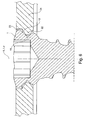
- Fig. 5 shows a bone screw 1, preferably as in Fig. 2 is formed within a provided with internal thread 22 through hole 23 in a bone plate 24.
- Both the bone plate 24 and the bone screw 1, which together form a (fixation) system 26, are also made of titanium.
- the longitudinal central axis L of the bone screw 1 encloses a longitudinal center axis LD of the passage opening 23 at an angle Y, which is 15 ° in the embodiment shown.
- the upper undercut flank 12 is supported in the plane of the drawing on the right on an internal thread flank 25 and is locked with this, so that the bone screw 1 is held stable in angle at the angle Y and the bone plate 24 is securely fixed.
- the bone screw 1 is supported with an underside of the screw head 6 at the inner edge of the internal thread flank 25 on the bone plate 24.
- system 26 fall the longitudinal center axis L of the bone screw 1 and the longitudinal center axis L F of the through hole 23 in the bone plate 24 together. It can be seen that the undercut ground 15 is arranged at a radial distance from the internal thread 22 and the bone screw 1 is axially supported with the upper undercut flank 12 at an inner upper edge of the internal thread 22. Due to the radial distance between relief groove 15 and internal thread 22, the friction is reduced.
Claims (8)
- Vis à os comprenant une tige (2) présentant un filetage pour os (3) et comprenant un filetage (7) présentant des rainures de filet disposées axialement à côté du filetage pour os (3), le filetage (7) étant pratiqué dans une portion axiale (8) d'une tête de vis (6) présentant un contour d'enveloppe conique, laquelle tête de vis dépasse vers l'extérieur au-delà de la tige (2), un pas du filetage pour os (3) et un pas du filetage (7) étant identiques,
caractérisée en ce que
le filetage (7) se termine avec une extrémité opposée au filetage pour os (3) dans un dégagement par rainure périphérique (11) qui est limité par un flanc de dégagement supérieur (12) prévu pour réaliser un blocage avec une plaque à os, réalisé sous forme de plan oblique, qui s'étend jusqu'au fond de rainure de filet (9) du filetage (7) se terminant dans le dégagement par rainure (11). - Vis à os selon la revendication 1,
caractérisée en ce
qu'un angle (α) entre un plan de dégagement par rainure (e) recevant un fond de dégagement par rainure, disposé transversalement à un axe médian longitudinal, et le flanc de dégagement supérieur (12), est choisi dans une plage de valeurs comprise entre environ 10° et environ 50°, de préférence entre environ 15° et environ 45°, de préférence entre environ 20° et environ 35°, ou vaut environ 30°. - Vis à os selon l'une quelconque des revendications précédentes,
caractérisée en ce que
les rainures de filet (10) se terminent radialement à l'intérieur sur une surface d'enveloppe cylindrique imaginaire ou sur une surface d'enveloppe conique imaginaire. - Vis à os selon l'une quelconque des revendications précédentes,
caractérisée en ce que
le filetage (7) est espacé axialement du filetage pour os (3), de préférence de telle sorte que les rainures de filetage du filetage (7) et le filetage pour os (3) soient disposés concentriquement par rapport à une ligne hélicoïdale commune imaginaire de pas uniforme. - Vis à os selon l'une quelconque des revendications précédentes,
caractérisée en ce que
le filetage périphérique (7) est un filetage (7) à plusieurs pas, notamment à trois pas, et/ou un filetage métrique. - Système comprenant une plaque à os (24) présentant au moins une ouverture de passage (23), en particulier avec un filetage interne (22), et une vis à os (1) selon l'une quelconque des revendications précédentes, le flanc de dégagement (12) pouvant être bloqué avec la plaque à os (24).
- Système selon la revendication 6,
caractérisé en ce que
la vis à os (1) est réalisée à partir d'un matériau plus dur que la plaque à os (24). - Système selon l'une quelconque des revendications 6 ou 7,
caractérisé en ce que
l'étendue radiale du flanc de dégagement supérieur (12) est supérieure au diamètre du coeur de l'ouverture de passage (23).
Applications Claiming Priority (1)
| Application Number | Priority Date | Filing Date | Title |
|---|---|---|---|
| DE200910049168 DE102009049168A1 (de) | 2009-10-12 | 2009-10-12 | Knochenschraube sowie System |
Publications (2)
| Publication Number | Publication Date |
|---|---|
| EP2308403A1 EP2308403A1 (fr) | 2011-04-13 |
| EP2308403B1 true EP2308403B1 (fr) | 2013-03-27 |
Family
ID=43501190
Family Applications (1)
| Application Number | Title | Priority Date | Filing Date |
|---|---|---|---|
| EP10013345A Not-in-force EP2308403B1 (fr) | 2009-10-12 | 2010-10-06 | Vis à os et système |
Country Status (2)
| Country | Link |
|---|---|
| EP (1) | EP2308403B1 (fr) |
| DE (1) | DE102009049168A1 (fr) |
Cited By (1)
| Publication number | Priority date | Publication date | Assignee | Title |
|---|---|---|---|---|
| EP2842504A1 (fr) | 2013-09-02 | 2015-03-04 | Aesculap Ag | Vis à os, plaque implantable et système formé des deux |
Families Citing this family (2)
| Publication number | Priority date | Publication date | Assignee | Title |
|---|---|---|---|---|
| CN106730043B (zh) * | 2016-12-19 | 2022-09-20 | 苏州西脉新诚生物科技有限公司 | 一种高强度可吸收骨折内固定骨螺钉 |
| US10426535B2 (en) * | 2017-01-05 | 2019-10-01 | Stryker European Holdings I, Llc | Self-holding screw head |
Family Cites Families (8)
| Publication number | Priority date | Publication date | Assignee | Title |
|---|---|---|---|---|
| DE19858889B4 (de) | 1998-12-19 | 2008-08-07 | Wolter, Dietmar, Prof. Dr.Med. | Fixationssystem für Knochen |
| US7695502B2 (en) * | 2000-02-01 | 2010-04-13 | Depuy Products, Inc. | Bone stabilization system including plate having fixed-angle holes together with unidirectional locking screws and surgeon-directed locking screws |
| US7717945B2 (en) * | 2002-07-22 | 2010-05-18 | Acumed Llc | Orthopedic systems |
| US7179260B2 (en) * | 2003-09-29 | 2007-02-20 | Smith & Nephew, Inc. | Bone plates and bone plate assemblies |
| WO2004086990A1 (fr) | 2003-04-03 | 2004-10-14 | Medartis Ag | Logement pour un element de blocage et element de blocage |
| US8574268B2 (en) * | 2004-01-26 | 2013-11-05 | DePuy Synthes Product, LLC | Highly-versatile variable-angle bone plate system |
| DE202005014850U1 (de) * | 2005-09-20 | 2007-02-01 | Karl Leibinger Medizintechnik Gmbh & Co. Kg | System zur Fixierung von Knochensegmenten oder -fragmenten |
| FR2910800B1 (fr) * | 2006-12-27 | 2009-07-10 | D L P Sarl | Dispositif d'osteosynthese comprenant un support muni d'au moins un orifice taraude associe a un appui en tronc de cone pour la reception d'une tige d'ancrage |
-
2009
- 2009-10-12 DE DE200910049168 patent/DE102009049168A1/de not_active Ceased
-
2010
- 2010-10-06 EP EP10013345A patent/EP2308403B1/fr not_active Not-in-force
Cited By (2)
| Publication number | Priority date | Publication date | Assignee | Title |
|---|---|---|---|---|
| EP2842504A1 (fr) | 2013-09-02 | 2015-03-04 | Aesculap Ag | Vis à os, plaque implantable et système formé des deux |
| DE102013109569A1 (de) | 2013-09-02 | 2015-03-05 | Aesculap Ag | Knochenschrauben, Implantatplatte und System daraus |
Also Published As
| Publication number | Publication date |
|---|---|
| DE102009049168A1 (de) | 2011-04-28 |
| EP2308403A1 (fr) | 2011-04-13 |
Similar Documents
| Publication | Publication Date | Title |
|---|---|---|
| DE60217782T2 (de) | Bolzen und Mutter | |
| EP1601297B1 (fr) | Vis de blocage pour clou intramedullaire | |
| EP2806174B1 (fr) | Elément de vis | |
| WO2005080802A1 (fr) | Vis autotaraudeuse | |
| WO2005079685A1 (fr) | Vis osseuse | |
| EP3353460B1 (fr) | Bouchon fileté | |
| EP0939235B1 (fr) | Vis | |
| EP3482092B9 (fr) | Vis à cheville | |
| DE102014000940A1 (de) | Schraube, Befestigungsanordnung und Verwendung einer Schraube | |
| EP1795148B1 (fr) | Implant dentaire | |
| EP3377777B1 (fr) | Vis de formage de filets ou de taraudage, en particulier pour utilisation dans du métal léger | |
| WO2000003648A1 (fr) | Vis d'osteosynthese | |
| EP2308403B1 (fr) | Vis à os et système | |
| EP3655669B1 (fr) | Vis à bois | |
| DE202004002878U1 (de) | Gewindeformende Schraube | |
| EP3726072B1 (fr) | Vis pour matériau à base de bois | |
| EP3034893B1 (fr) | Vis-cheville | |
| EP3374649B1 (fr) | Vis autotaraudeuse | |
| EP3586015A1 (fr) | Vis | |
| EP3380737A1 (fr) | Vis à béton | |
| EP2593683A1 (fr) | Vis autocentreuse | |
| EP3943763B1 (fr) | Vis à bois ou à matière plastique | |
| WO2018015482A1 (fr) | Système de vis pédiculaire muni d'une vis de verrouillage comprenant une partie filetée | |
| EP2261517A1 (fr) | Vis autotaraudeuse | |
| EP2470801B1 (fr) | Vis |
Legal Events
| Date | Code | Title | Description |
|---|---|---|---|
| PUAI | Public reference made under article 153(3) epc to a published international application that has entered the european phase |
Free format text: ORIGINAL CODE: 0009012 |
|
| AK | Designated contracting states |
Kind code of ref document: A1 Designated state(s): AL AT BE BG CH CY CZ DE DK EE ES FI FR GB GR HR HU IE IS IT LI LT LU LV MC MK MT NL NO PL PT RO RS SE SI SK SM TR |
|
| AX | Request for extension of the european patent |
Extension state: BA ME |
|
| 17P | Request for examination filed |
Effective date: 20111013 |
|
| 17Q | First examination report despatched |
Effective date: 20120627 |
|
| GRAP | Despatch of communication of intention to grant a patent |
Free format text: ORIGINAL CODE: EPIDOSNIGR1 |
|
| GRAS | Grant fee paid |
Free format text: ORIGINAL CODE: EPIDOSNIGR3 |
|
| GRAA | (expected) grant |
Free format text: ORIGINAL CODE: 0009210 |
|
| AK | Designated contracting states |
Kind code of ref document: B1 Designated state(s): AL AT BE BG CH CY CZ DE DK EE ES FI FR GB GR HR HU IE IS IT LI LT LU LV MC MK MT NL NO PL PT RO RS SE SI SK SM TR |
|
| REG | Reference to a national code |
Ref country code: GB Ref legal event code: FG4D Free format text: NOT ENGLISH |
|
| REG | Reference to a national code |
Ref country code: CH Ref legal event code: EP |
|
| REG | Reference to a national code |
Ref country code: AT Ref legal event code: REF Ref document number: 602864 Country of ref document: AT Kind code of ref document: T Effective date: 20130415 |
|
| REG | Reference to a national code |
Ref country code: IE Ref legal event code: FG4D Free format text: LANGUAGE OF EP DOCUMENT: GERMAN |
|
| REG | Reference to a national code |
Ref country code: DE Ref legal event code: R096 Ref document number: 502010002678 Country of ref document: DE Effective date: 20130529 |
|
| REG | Reference to a national code |
Ref country code: CH Ref legal event code: NV Representative=s name: BODENSEEPATENT GMBH, CH |
|
| PG25 | Lapsed in a contracting state [announced via postgrant information from national office to epo] |
Ref country code: BG Free format text: LAPSE BECAUSE OF FAILURE TO SUBMIT A TRANSLATION OF THE DESCRIPTION OR TO PAY THE FEE WITHIN THE PRESCRIBED TIME-LIMIT Effective date: 20130627 Ref country code: SE Free format text: LAPSE BECAUSE OF FAILURE TO SUBMIT A TRANSLATION OF THE DESCRIPTION OR TO PAY THE FEE WITHIN THE PRESCRIBED TIME-LIMIT Effective date: 20130327 Ref country code: NO Free format text: LAPSE BECAUSE OF FAILURE TO SUBMIT A TRANSLATION OF THE DESCRIPTION OR TO PAY THE FEE WITHIN THE PRESCRIBED TIME-LIMIT Effective date: 20130627 Ref country code: LT Free format text: LAPSE BECAUSE OF FAILURE TO SUBMIT A TRANSLATION OF THE DESCRIPTION OR TO PAY THE FEE WITHIN THE PRESCRIBED TIME-LIMIT Effective date: 20130327 |
|
| REG | Reference to a national code |
Ref country code: LT Ref legal event code: MG4D |
|
| PG25 | Lapsed in a contracting state [announced via postgrant information from national office to epo] |
Ref country code: SI Free format text: LAPSE BECAUSE OF FAILURE TO SUBMIT A TRANSLATION OF THE DESCRIPTION OR TO PAY THE FEE WITHIN THE PRESCRIBED TIME-LIMIT Effective date: 20130327 Ref country code: FI Free format text: LAPSE BECAUSE OF FAILURE TO SUBMIT A TRANSLATION OF THE DESCRIPTION OR TO PAY THE FEE WITHIN THE PRESCRIBED TIME-LIMIT Effective date: 20130327 Ref country code: LV Free format text: LAPSE BECAUSE OF FAILURE TO SUBMIT A TRANSLATION OF THE DESCRIPTION OR TO PAY THE FEE WITHIN THE PRESCRIBED TIME-LIMIT Effective date: 20130327 Ref country code: GR Free format text: LAPSE BECAUSE OF FAILURE TO SUBMIT A TRANSLATION OF THE DESCRIPTION OR TO PAY THE FEE WITHIN THE PRESCRIBED TIME-LIMIT Effective date: 20130628 |
|
| REG | Reference to a national code |
Ref country code: NL Ref legal event code: VDEP Effective date: 20130327 |
|
| PG25 | Lapsed in a contracting state [announced via postgrant information from national office to epo] |
Ref country code: HR Free format text: LAPSE BECAUSE OF FAILURE TO SUBMIT A TRANSLATION OF THE DESCRIPTION OR TO PAY THE FEE WITHIN THE PRESCRIBED TIME-LIMIT Effective date: 20130327 |
|
| PG25 | Lapsed in a contracting state [announced via postgrant information from national office to epo] |
Ref country code: SK Free format text: LAPSE BECAUSE OF FAILURE TO SUBMIT A TRANSLATION OF THE DESCRIPTION OR TO PAY THE FEE WITHIN THE PRESCRIBED TIME-LIMIT Effective date: 20130327 Ref country code: RO Free format text: LAPSE BECAUSE OF FAILURE TO SUBMIT A TRANSLATION OF THE DESCRIPTION OR TO PAY THE FEE WITHIN THE PRESCRIBED TIME-LIMIT Effective date: 20130327 Ref country code: EE Free format text: LAPSE BECAUSE OF FAILURE TO SUBMIT A TRANSLATION OF THE DESCRIPTION OR TO PAY THE FEE WITHIN THE PRESCRIBED TIME-LIMIT Effective date: 20130327 Ref country code: CZ Free format text: LAPSE BECAUSE OF FAILURE TO SUBMIT A TRANSLATION OF THE DESCRIPTION OR TO PAY THE FEE WITHIN THE PRESCRIBED TIME-LIMIT Effective date: 20130327 Ref country code: NL Free format text: LAPSE BECAUSE OF FAILURE TO SUBMIT A TRANSLATION OF THE DESCRIPTION OR TO PAY THE FEE WITHIN THE PRESCRIBED TIME-LIMIT Effective date: 20130327 Ref country code: PT Free format text: LAPSE BECAUSE OF FAILURE TO SUBMIT A TRANSLATION OF THE DESCRIPTION OR TO PAY THE FEE WITHIN THE PRESCRIBED TIME-LIMIT Effective date: 20130729 Ref country code: ES Free format text: LAPSE BECAUSE OF FAILURE TO SUBMIT A TRANSLATION OF THE DESCRIPTION OR TO PAY THE FEE WITHIN THE PRESCRIBED TIME-LIMIT Effective date: 20130708 Ref country code: IS Free format text: LAPSE BECAUSE OF FAILURE TO SUBMIT A TRANSLATION OF THE DESCRIPTION OR TO PAY THE FEE WITHIN THE PRESCRIBED TIME-LIMIT Effective date: 20130727 |
|
| PG25 | Lapsed in a contracting state [announced via postgrant information from national office to epo] |
Ref country code: PL Free format text: LAPSE BECAUSE OF FAILURE TO SUBMIT A TRANSLATION OF THE DESCRIPTION OR TO PAY THE FEE WITHIN THE PRESCRIBED TIME-LIMIT Effective date: 20130327 Ref country code: CY Free format text: LAPSE BECAUSE OF FAILURE TO SUBMIT A TRANSLATION OF THE DESCRIPTION OR TO PAY THE FEE WITHIN THE PRESCRIBED TIME-LIMIT Effective date: 20130327 |
|
| REG | Reference to a national code |
Ref country code: DE Ref legal event code: R097 Ref document number: 502010002678 Country of ref document: DE |
|
| REG | Reference to a national code |
Ref country code: CH Ref legal event code: PUE Owner name: ZIMMER GMBH, CH Free format text: FORMER OWNER: NORMED MEDIZIN-TECHNIK GMBH, DE |
|
| PG25 | Lapsed in a contracting state [announced via postgrant information from national office to epo] |
Ref country code: DK Free format text: LAPSE BECAUSE OF FAILURE TO SUBMIT A TRANSLATION OF THE DESCRIPTION OR TO PAY THE FEE WITHIN THE PRESCRIBED TIME-LIMIT Effective date: 20130327 |
|
| PLAA | Information modified related to event that no opposition was filed |
Free format text: ORIGINAL CODE: 0009299DELT |
|
| PLBE | No opposition filed within time limit |
Free format text: ORIGINAL CODE: 0009261 |
|
| STAA | Information on the status of an ep patent application or granted ep patent |
Free format text: STATUS: NO OPPOSITION FILED WITHIN TIME LIMIT |
|
| REG | Reference to a national code |
Ref country code: DE Ref legal event code: R082 Ref document number: 502010002678 Country of ref document: DE Representative=s name: MANITZ, FINSTERWALD & PARTNER GBR, DE |
|
| PG25 | Lapsed in a contracting state [announced via postgrant information from national office to epo] |
Ref country code: IT Free format text: LAPSE BECAUSE OF FAILURE TO SUBMIT A TRANSLATION OF THE DESCRIPTION OR TO PAY THE FEE WITHIN THE PRESCRIBED TIME-LIMIT Effective date: 20130327 |
|
| R26N | No opposition filed (corrected) |
Effective date: 20140103 |
|
| REG | Reference to a national code |
Ref country code: DE Ref legal event code: R082 Ref document number: 502010002678 Country of ref document: DE Representative=s name: MANITZ, FINSTERWALD & PARTNER GBR, DE Effective date: 20140203 Ref country code: DE Ref legal event code: R081 Ref document number: 502010002678 Country of ref document: DE Owner name: ZIMMER GMBH, CH Free format text: FORMER OWNER: NORMED MEDIZIN-TECHNIK GMBH, 78532 TUTTLINGEN, DE Effective date: 20140203 Ref country code: DE Ref legal event code: R082 Ref document number: 502010002678 Country of ref document: DE Representative=s name: MANITZ FINSTERWALD PATENTANWAELTE PARTMBB, DE Effective date: 20140203 |
|
| REG | Reference to a national code |
Ref country code: DE Ref legal event code: R097 Ref document number: 502010002678 Country of ref document: DE Effective date: 20140103 |
|
| PG25 | Lapsed in a contracting state [announced via postgrant information from national office to epo] |
Ref country code: MC Free format text: LAPSE BECAUSE OF FAILURE TO SUBMIT A TRANSLATION OF THE DESCRIPTION OR TO PAY THE FEE WITHIN THE PRESCRIBED TIME-LIMIT Effective date: 20130327 |
|
| REG | Reference to a national code |
Ref country code: CH Ref legal event code: NV Representative=s name: DR. GRAF AND PARTNER AG INTELLECTUAL PROPERTY, CH |
|
| REG | Reference to a national code |
Ref country code: GB Ref legal event code: 732E Free format text: REGISTERED BETWEEN 20140508 AND 20140514 |
|
| REG | Reference to a national code |
Ref country code: FR Ref legal event code: TP Owner name: ZIMMER GMBH, CH Effective date: 20140526 |
|
| REG | Reference to a national code |
Ref country code: IE Ref legal event code: MM4A |
|
| PG25 | Lapsed in a contracting state [announced via postgrant information from national office to epo] |
Ref country code: IE Free format text: LAPSE BECAUSE OF NON-PAYMENT OF DUE FEES Effective date: 20131006 |
|
| PG25 | Lapsed in a contracting state [announced via postgrant information from national office to epo] |
Ref country code: SM Free format text: LAPSE BECAUSE OF FAILURE TO SUBMIT A TRANSLATION OF THE DESCRIPTION OR TO PAY THE FEE WITHIN THE PRESCRIBED TIME-LIMIT Effective date: 20130327 |
|
| PG25 | Lapsed in a contracting state [announced via postgrant information from national office to epo] |
Ref country code: TR Free format text: LAPSE BECAUSE OF FAILURE TO SUBMIT A TRANSLATION OF THE DESCRIPTION OR TO PAY THE FEE WITHIN THE PRESCRIBED TIME-LIMIT Effective date: 20130327 |
|
| PG25 | Lapsed in a contracting state [announced via postgrant information from national office to epo] |
Ref country code: LU Free format text: LAPSE BECAUSE OF NON-PAYMENT OF DUE FEES Effective date: 20131006 Ref country code: RS Free format text: LAPSE BECAUSE OF FAILURE TO SUBMIT A TRANSLATION OF THE DESCRIPTION OR TO PAY THE FEE WITHIN THE PRESCRIBED TIME-LIMIT Effective date: 20130627 Ref country code: MK Free format text: LAPSE BECAUSE OF FAILURE TO SUBMIT A TRANSLATION OF THE DESCRIPTION OR TO PAY THE FEE WITHIN THE PRESCRIBED TIME-LIMIT Effective date: 20130327 Ref country code: HU Free format text: LAPSE BECAUSE OF FAILURE TO SUBMIT A TRANSLATION OF THE DESCRIPTION OR TO PAY THE FEE WITHIN THE PRESCRIBED TIME-LIMIT; INVALID AB INITIO Effective date: 20101006 |
|
| PG25 | Lapsed in a contracting state [announced via postgrant information from national office to epo] |
Ref country code: MT Free format text: LAPSE BECAUSE OF FAILURE TO SUBMIT A TRANSLATION OF THE DESCRIPTION OR TO PAY THE FEE WITHIN THE PRESCRIBED TIME-LIMIT Effective date: 20130327 |
|
| REG | Reference to a national code |
Ref country code: FR Ref legal event code: PLFP Year of fee payment: 7 |
|
| REG | Reference to a national code |
Ref country code: FR Ref legal event code: PLFP Year of fee payment: 8 |
|
| REG | Reference to a national code |
Ref country code: FR Ref legal event code: PLFP Year of fee payment: 9 |
|
| PG25 | Lapsed in a contracting state [announced via postgrant information from national office to epo] |
Ref country code: AL Free format text: LAPSE BECAUSE OF FAILURE TO SUBMIT A TRANSLATION OF THE DESCRIPTION OR TO PAY THE FEE WITHIN THE PRESCRIBED TIME-LIMIT Effective date: 20130327 |
|
| PGFP | Annual fee paid to national office [announced via postgrant information from national office to epo] |
Ref country code: FR Payment date: 20200921 Year of fee payment: 11 Ref country code: GB Payment date: 20200918 Year of fee payment: 11 |
|
| PGFP | Annual fee paid to national office [announced via postgrant information from national office to epo] |
Ref country code: CH Payment date: 20200922 Year of fee payment: 11 Ref country code: BE Payment date: 20200917 Year of fee payment: 11 |
|
| PGFP | Annual fee paid to national office [announced via postgrant information from national office to epo] |
Ref country code: DE Payment date: 20200918 Year of fee payment: 11 Ref country code: AT Payment date: 20200909 Year of fee payment: 11 |
|
| REG | Reference to a national code |
Ref country code: DE Ref legal event code: R119 Ref document number: 502010002678 Country of ref document: DE |
|
| REG | Reference to a national code |
Ref country code: CH Ref legal event code: PL |
|
| REG | Reference to a national code |
Ref country code: AT Ref legal event code: MM01 Ref document number: 602864 Country of ref document: AT Kind code of ref document: T Effective date: 20211006 |
|
| REG | Reference to a national code |
Ref country code: BE Ref legal event code: MM Effective date: 20211031 |
|
| GBPC | Gb: european patent ceased through non-payment of renewal fee |
Effective date: 20211006 |
|
| PG25 | Lapsed in a contracting state [announced via postgrant information from national office to epo] |
Ref country code: GB Free format text: LAPSE BECAUSE OF NON-PAYMENT OF DUE FEES Effective date: 20211006 Ref country code: DE Free format text: LAPSE BECAUSE OF NON-PAYMENT OF DUE FEES Effective date: 20220503 Ref country code: BE Free format text: LAPSE BECAUSE OF NON-PAYMENT OF DUE FEES Effective date: 20211031 |
|
| PG25 | Lapsed in a contracting state [announced via postgrant information from national office to epo] |
Ref country code: LI Free format text: LAPSE BECAUSE OF NON-PAYMENT OF DUE FEES Effective date: 20211031 Ref country code: CH Free format text: LAPSE BECAUSE OF NON-PAYMENT OF DUE FEES Effective date: 20211031 Ref country code: AT Free format text: LAPSE BECAUSE OF NON-PAYMENT OF DUE FEES Effective date: 20211006 |
|
| PG25 | Lapsed in a contracting state [announced via postgrant information from national office to epo] |
Ref country code: FR Free format text: LAPSE BECAUSE OF NON-PAYMENT OF DUE FEES Effective date: 20211031 |