EP2307805B1 - Chambre de combustion de moteur a turbine a gaz comportant des deflecteurs en cmc - Google Patents
Chambre de combustion de moteur a turbine a gaz comportant des deflecteurs en cmc Download PDFInfo
- Publication number
- EP2307805B1 EP2307805B1 EP09772283.9A EP09772283A EP2307805B1 EP 2307805 B1 EP2307805 B1 EP 2307805B1 EP 09772283 A EP09772283 A EP 09772283A EP 2307805 B1 EP2307805 B1 EP 2307805B1
- Authority
- EP
- European Patent Office
- Prior art keywords
- deflector
- combustion chamber
- sleeve
- chamber
- cup
- Prior art date
- Legal status (The legal status is an assumption and is not a legal conclusion. Google has not performed a legal analysis and makes no representation as to the accuracy of the status listed.)
- Active
Links
Images
Classifications
-
- F—MECHANICAL ENGINEERING; LIGHTING; HEATING; WEAPONS; BLASTING
- F23—COMBUSTION APPARATUS; COMBUSTION PROCESSES
- F23R—GENERATING COMBUSTION PRODUCTS OF HIGH PRESSURE OR HIGH VELOCITY, e.g. GAS-TURBINE COMBUSTION CHAMBERS
- F23R3/00—Continuous combustion chambers using liquid or gaseous fuel
- F23R3/28—Continuous combustion chambers using liquid or gaseous fuel characterised by the fuel supply
- F23R3/283—Attaching or cooling of fuel injecting means including supports for fuel injectors, stems, or lances
Definitions
- the present invention relates to the field of gas turbine engines and in particular that of the combustion chambers of such engines.
- the combustion chamber of a gas turbine engine receives compressed air from the upstream high pressure compressor and provides a combustion-heated gas in a fuel-fired combustion zone.
- the chamber thus comprises an upstream chamber bottom wall on which the different fuel injection systems are fixed.
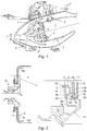
- the figure 1 shows a chamber of the prior art.
- the annular chamber 1 is housed inside a housing 2 of the engine downstream of the diffuser 3 of compressed air. It comprises an inner wall 4 and an outer wall 5 delimiting between them a combustion zone.
- the chamber In its upstream part the chamber comprises a transverse wall 6 of bottom chamber on which are provided openings each equipped with a system 7 for supplying carbureted air.
- Such a system is supplied with fuel from a liquid fuel injector and includes concentric annular grids to create swirling air streams promoting their mixing with the sprayed fuel web.
- Part of the air from the diffuser is diverted from the fuel intake zone through the shroud 8 and flows along and out of the outer wall as well as along and out of the inner wall.
- the primary combustion zone is therefore immediately downstream of the wall of the chamber bottom.
- Deflectors 9 made of metallic material line the inside of the wall of the chamber bottom and serve to protect it from the intense radiation produced in the primary combustion zone.
- Air is introduced through orifices made in the wall of the chamber bottom behind the baffles to ensure their cooling. This air flows along the rear face of the baffles and is then guided to form a film along the longitudinal outer walls of the chamber.
- a gas turbine engine combustion chamber according to the preamble of claim 1 is shown in US 6,212,870 B1 .
- baffle CMC ceramic matrix composite
- CMCs ceramic matrix components
- They are formed of a carbon fiber reinforcement or refractory material and a ceramic matrix.
- the manufacture of a CMC comprises the production of a fiber preform intended to constitute the reinforcement of the structure, and the densification of the preform by the ceramic material of the matrix.
- CMCs have the advantage of maintaining their mechanical properties up to high temperatures in an oxidizing medium.
- a CMC has a thermal expansion rate four times lower than the metal used for the chamber.
- this material can not be welded or soldered.
- the applicant has set a goal to develop a manner of mounting deflectors of CMC type material on the bottom wall of a combustion chamber.
- this object is achieved with a combustion chamber having the features reported in the main claim.
- the sheath is preferably fixed by brazing to the wall and the mechanical attachment means is interconnection.
- the cup comprises a radial flange through which it is fixed by welding to the metal sleeve.
- the carbureted air supply system comprises a bowl fixed by a flange to the metal sheath.
- the mechanical attachment means of the baffle cooperates with a deflector support attached to the sleeve.
- This support forms an intermediate piece which makes it possible to move the brazing zones away from the metal parts without damaging the CMC material constituting the deflector.
- the cylindrical portion of the deflector is integral with a cylindrical element forming a cup, housed, with cold play, inside the annular flange of the deflector, said cup member ensuring the guiding of the deflector when the temperature has increased.
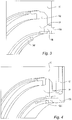
- a chamber bottom according to one embodiment of the invention is shown.
- the bottom wall 11 of the chamber 10 is protected from the radiation of the combustion zone by a deflector 12 made of CMC material.
- the shape of the deflector is substantially the same as that of the deflector 9 of the prior art with a generally flat portion 12A which is placed parallel to the wall 11 and two portions 12b curved towards the outer and inner walls.
- the deflector 12 is open in its central part with a cylindrical portion 12c having the same axis as the fuel air supply system 13.
- a metal sleeve 14 In the opening of the wall 11 of the chamber bottom, is fixed a metal sleeve 14.
- a solder 14a holds the sleeve 14 against the inner edge of the opening of the wall 11.
- the sleeve comprises a cylindrical portion 14b and a portion radial 14c, the latter providing a space with a stopper 15 which is welded to its periphery.
- 14d transverse teeth facing the axis of the opening of the wall 11 are formed inside the cylindrical portion 14b of the sleeve 14.
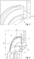
- a centering cup 16 comprises a cylindrical portion 16a and a flange 16b radial and transverse. The cup 16 is disposed inside the cylindrical portion 14b of the sleeve and fixed by a weld bead 16c peripheral to the sleeve 14.
- the cylindrical portion 16a of the cup is inside the cylindrical portion 12c.
- the deflector 12 comprises a transverse groove 12c1 on the outer face of the cylindrical portion 12c, forming housing teeth 14d of the sleeve.
- the groove is perforated to allow the axial passage of the teeth 14d to the assembly and the locking by rotation of the sleeve relative to the cylindrical portion 12c of the baffle 12.
- This mechanical fastening mode from the baffle to the sheath is of the type interconnection. Other modes of mechanical fixing are possible.
- the cylindrical portion 16a of the cup is inside the cylindrical portion 12c, with mounting a radial clearance.
- the device for injecting and carburizing air is represented generally by the reference 13. It is not detailed to the extent that the subject of the invention does not concern it.
- the diverging bowl 13a of the device comprises externally a transverse flange 13b housed in the space formed between the radial face 14c of the sleeve 14 and the stopper 15.
- the sheath 14 is fixed, figure 5 , brazing it on the chamber bottom with the solder bead 14a, figure 2 and an anti-rotation pin 18 is placed between the diameter of the sleeve and that of the deflector.
- the centering cup 16 is slid into the cylindrical portion 12c of the deflector. And the cup is fixed by a point or a weld bead 16c between the latter and the sleeve 14.
- the fuel injection device 13 is mounted that is immobilized by the stop plate 15. It is welded to the sheath.
- This mounting mode of the deflector makes it possible to immobilize it in the wall of the chamber bottom by a mechanical means of attachment.
- the welds are made only between the metal parts. Differential expansion of the deflectors with respect to the metallic environment is taken into account by means of the centering cup which, by expanding radially, immobilizes the deflector in position.
- the clearance between the sleeve and the baffle on the one hand and the baffle and the centering cup on the other hand are to be optimized according to the operating temperatures and the diameter of the parts.
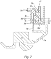
- the assembly principle is generally the same as before; we simply modified the sheath and the cup.
- a baffle support sleeve 26, annular, comprises transverse teeth 26d cooperating with the outer groove 12c1 of the annular flange of the deflector.
- the support sleeve 26 is slid axially from the outside of the chamber with introduction of the teeth 26d into the groove 12c1 by the openings (not visible) of the groove.
- a rotation around the axis of the opening allows the interconnection of the support sleeve 26 with the deflector.
- the support sleeve 26 has a cylindrical portion 26a, forming a cylindrical centering cup radially inner which fits inside the flange 12c. In cold mounting, a clearance is provided between the cylindrical portion 26a of the support sleeve and the flange 12c of the deflector. The centering is ensured by the mechanical attachment to clutch.
- the deflector support sleeve expands more than the deflector CMC material.
- the cylindrical portion bears against the inner face of the clamp 12c with clamping and ensures the centering of the deflector.
- the fuel injection device 13 is mounted as before by the outside of the chamber, a transverse flange 13b being immobilized between the rear face of the deflector support 26 and a stop cup 15 brazed to the support.
Landscapes
- Engineering & Computer Science (AREA)
- Chemical & Material Sciences (AREA)
- Combustion & Propulsion (AREA)
- Mechanical Engineering (AREA)
- General Engineering & Computer Science (AREA)
- Combustion Methods Of Internal-Combustion Engines (AREA)
- Fuel-Injection Apparatus (AREA)
- Cylinder Crankcases Of Internal Combustion Engines (AREA)
Applications Claiming Priority (2)
| Application Number | Priority Date | Filing Date | Title |
|---|---|---|---|
| FR0803226A FR2932251B1 (fr) | 2008-06-10 | 2008-06-10 | Chambre de combustion de moteur a turbine a gaz comportant des deflecteurs en cmc |
| PCT/EP2009/057147 WO2010000583A2 (fr) | 2008-06-10 | 2009-06-10 | Chambre de combustion de moteur a turbine a gaz comportant des deflecteurs en cmc |
Publications (2)
| Publication Number | Publication Date |
|---|---|
| EP2307805A2 EP2307805A2 (fr) | 2011-04-13 |
| EP2307805B1 true EP2307805B1 (fr) | 2017-03-15 |
Family
ID=40289257
Family Applications (1)
| Application Number | Title | Priority Date | Filing Date |
|---|---|---|---|
| EP09772283.9A Active EP2307805B1 (fr) | 2008-06-10 | 2009-06-10 | Chambre de combustion de moteur a turbine a gaz comportant des deflecteurs en cmc |
Country Status (9)
| Country | Link |
|---|---|
| US (1) | US8756935B2 (enExample) |
| EP (1) | EP2307805B1 (enExample) |
| JP (1) | JP5475757B2 (enExample) |
| CN (1) | CN102057224B (enExample) |
| BR (1) | BRPI0914905B1 (enExample) |
| CA (1) | CA2727254C (enExample) |
| FR (1) | FR2932251B1 (enExample) |
| RU (1) | RU2507452C2 (enExample) |
| WO (1) | WO2010000583A2 (enExample) |
Families Citing this family (23)
| Publication number | Priority date | Publication date | Assignee | Title |
|---|---|---|---|---|
| US8943835B2 (en) * | 2010-05-10 | 2015-02-03 | General Electric Company | Gas turbine engine combustor with CMC heat shield and methods therefor |
| FR2964177B1 (fr) | 2010-08-27 | 2012-08-24 | Snecma | Chambre de combustion de moteur d?aeronef et procede de fixation d?un systeme d?injection dans une chambre de combustion de moteur d?aeronef |
| DE102013007443A1 (de) * | 2013-04-30 | 2014-10-30 | Rolls-Royce Deutschland Ltd & Co Kg | Brennerdichtung für Gasturbinen-Brennkammerkopf und Hitzeschild |
| FR3026827B1 (fr) * | 2014-10-01 | 2019-06-07 | Safran Aircraft Engines | Chambre de combustion de turbomachine |
| US10041676B2 (en) * | 2015-07-08 | 2018-08-07 | General Electric Company | Sealed conical-flat dome for flight engine combustors |
| US20170059159A1 (en) | 2015-08-25 | 2017-03-02 | Rolls-Royce Corporation | Cmc combustor shell with integral chutes |
| US11149646B2 (en) | 2015-09-02 | 2021-10-19 | General Electric Company | Piston ring assembly for a turbine engine |
| US10168051B2 (en) | 2015-09-02 | 2019-01-01 | General Electric Company | Combustor assembly for a turbine engine |
| US9976746B2 (en) | 2015-09-02 | 2018-05-22 | General Electric Company | Combustor assembly for a turbine engine |
| GB2543803B (en) * | 2015-10-29 | 2019-10-30 | Rolls Royce Plc | A combustion chamber assembly |
| US10317085B2 (en) * | 2016-02-25 | 2019-06-11 | General Electric Company | Combustor assembly |
| US10378769B2 (en) | 2016-09-30 | 2019-08-13 | General Electric Company | Combustor heat shield and attachment features |
| US10371382B2 (en) * | 2016-09-30 | 2019-08-06 | General Electric Company | Combustor heat shield and attachment features |
| US10495310B2 (en) | 2016-09-30 | 2019-12-03 | General Electric Company | Combustor heat shield and attachment features |
| US10378772B2 (en) | 2017-01-19 | 2019-08-13 | General Electric Company | Combustor heat shield sealing |
| US11111858B2 (en) | 2017-01-27 | 2021-09-07 | General Electric Company | Cool core gas turbine engine |
| US10816199B2 (en) | 2017-01-27 | 2020-10-27 | General Electric Company | Combustor heat shield and attachment features |
| US10690347B2 (en) | 2017-02-01 | 2020-06-23 | General Electric Company | CMC combustor deflector |
| US10837640B2 (en) | 2017-03-06 | 2020-11-17 | General Electric Company | Combustion section of a gas turbine engine |
| US11402097B2 (en) | 2018-01-03 | 2022-08-02 | General Electric Company | Combustor assembly for a turbine engine |
| FR3084731B1 (fr) * | 2019-02-19 | 2020-07-03 | Safran Aircraft Engines | Chambre de combustion pour une turbomachine |
| US11649964B2 (en) * | 2020-12-01 | 2023-05-16 | Raytheon Technologies Corporation | Fuel injector assembly for a turbine engine |
| US11428160B2 (en) | 2020-12-31 | 2022-08-30 | General Electric Company | Gas turbine engine with interdigitated turbine and gear assembly |
Family Cites Families (28)
| Publication number | Priority date | Publication date | Assignee | Title |
|---|---|---|---|---|
| US4180974A (en) * | 1977-10-31 | 1980-01-01 | General Electric Company | Combustor dome sleeve |
| SU1002736A2 (ru) * | 1981-09-29 | 1983-03-07 | Центральный Научно-Исследовательский И Конструкторский Институт Топливной Аппаратуры Автотракторных И Стационарных Двигателей | Камера сгорани |
| US5117637A (en) * | 1990-08-02 | 1992-06-02 | General Electric Company | Combustor dome assembly |
| DE19515537A1 (de) * | 1995-04-27 | 1996-10-31 | Bmw Rolls Royce Gmbh | Kopfteil einer Gasturbinen-Ringbrennkammer |
| JPH08312961A (ja) * | 1995-05-16 | 1996-11-26 | Nissan Motor Co Ltd | ガスタービンの燃焼器 |
| FR2753779B1 (fr) * | 1996-09-26 | 1998-10-16 | Systeme d'injection aerodynamique d'un melange air carburant | |
| JPH1166893A (ja) * | 1997-08-22 | 1999-03-09 | Mitsubishi Electric Corp | 半導体記憶装置 |
| US5970716A (en) * | 1997-10-02 | 1999-10-26 | General Electric Company | Apparatus for retaining centerbody between adjacent domes of multiple annular combustor employing interference and clamping fits |
| US6212870B1 (en) * | 1998-09-22 | 2001-04-10 | General Electric Company | Self fixturing combustor dome assembly |
| US6397603B1 (en) * | 2000-05-05 | 2002-06-04 | The United States Of America As Represented By The Secretary Of The Air Force | Conbustor having a ceramic matrix composite liner |
| US6546732B1 (en) * | 2001-04-27 | 2003-04-15 | General Electric Company | Methods and apparatus for cooling gas turbine engine combustors |
| US6442940B1 (en) * | 2001-04-27 | 2002-09-03 | General Electric Company | Gas-turbine air-swirler attached to dome and combustor in single brazing operation |
| US6581386B2 (en) * | 2001-09-29 | 2003-06-24 | General Electric Company | Threaded combustor baffle |
| FR2832493B1 (fr) * | 2001-11-21 | 2004-07-09 | Snecma Moteurs | Systeme d'injection multi-etages d'un melange air/carburant dans une chambre de combustion de turbomachine |
| FR2859272B1 (fr) * | 2003-09-02 | 2005-10-14 | Snecma Moteurs | Systeme d'injection air/carburant, dans une chambre de combustion de turbomachine, ayant des moyens de generation de plasmas froids |
| RU2280814C1 (ru) * | 2004-12-27 | 2006-07-27 | Акционерное общество открытого типа Авиамоторный научно-технический комплекс "Союз" | Кольцевая камера сгорания газотурбинного двигателя |
| US7673460B2 (en) * | 2005-06-07 | 2010-03-09 | Snecma | System of attaching an injection system to a turbojet combustion chamber base |
| FR2886714B1 (fr) * | 2005-06-07 | 2007-09-07 | Snecma Moteurs Sa | Systeme d'injection anti-rotatif pour turbo-reacteur |
| FR2893390B1 (fr) * | 2005-11-15 | 2011-04-01 | Snecma | Fond de chambre de combustion avec ventilation |
| FR2894327B1 (fr) * | 2005-12-05 | 2008-05-16 | Snecma Sa | Dispositif d'injection d'un melange d'air et de carburant, chambre de combustion et turbomachine munies d'un tel dispositif |
| FR2897107B1 (fr) * | 2006-02-09 | 2013-01-18 | Snecma | Paroi transversale de chambre de combustion munie de trous de multiperforation |
| FR2897922B1 (fr) * | 2006-02-27 | 2008-10-10 | Snecma Sa | Agencement pour une chambre de combustion de turboreacteur |
| FR2901349B1 (fr) * | 2006-05-19 | 2008-09-05 | Snecma Sa | Chambre de combustion d'une turbomachine |
| FR2903171B1 (fr) * | 2006-06-29 | 2008-10-17 | Snecma Sa | Agencement a liaison par crabot pour chambre de combustion de turbomachine |
| FR2903170B1 (fr) * | 2006-06-29 | 2011-12-23 | Snecma | Dispositif d'injection d'un melange d'air et de carburant, chambre de combustion et turbomachine munies d'un tel dispositif |
| US8863528B2 (en) * | 2006-07-27 | 2014-10-21 | United Technologies Corporation | Ceramic combustor can for a gas turbine engine |
| FR2908867B1 (fr) * | 2006-11-16 | 2012-06-15 | Snecma | Dispositif d'injection d'un melange d'air et de carburant, chambre de combustion et turbomachine munies d'un tel dispositif |
| FR2941288B1 (fr) * | 2009-01-16 | 2011-02-18 | Snecma | Dispositif d'injection d'un melange d'air et de carburant dans une chambre de combustion de turbomachine |
-
2008
- 2008-06-10 FR FR0803226A patent/FR2932251B1/fr active Active
-
2009
- 2009-06-10 US US12/997,266 patent/US8756935B2/en active Active
- 2009-06-10 WO PCT/EP2009/057147 patent/WO2010000583A2/fr not_active Ceased
- 2009-06-10 JP JP2011512971A patent/JP5475757B2/ja active Active
- 2009-06-10 CA CA2727254A patent/CA2727254C/fr active Active
- 2009-06-10 RU RU2010154030/06A patent/RU2507452C2/ru active
- 2009-06-10 CN CN2009801216000A patent/CN102057224B/zh active Active
- 2009-06-10 BR BRPI0914905A patent/BRPI0914905B1/pt active IP Right Grant
- 2009-06-10 EP EP09772283.9A patent/EP2307805B1/fr active Active
Non-Patent Citations (1)
| Title |
|---|
| None * |
Also Published As
| Publication number | Publication date |
|---|---|
| CN102057224B (zh) | 2013-04-24 |
| JP2011523020A (ja) | 2011-08-04 |
| CA2727254C (fr) | 2016-08-23 |
| FR2932251A1 (fr) | 2009-12-11 |
| US8756935B2 (en) | 2014-06-24 |
| EP2307805A2 (fr) | 2011-04-13 |
| JP5475757B2 (ja) | 2014-04-16 |
| CA2727254A1 (fr) | 2010-01-07 |
| RU2507452C2 (ru) | 2014-02-20 |
| RU2010154030A (ru) | 2012-07-20 |
| FR2932251B1 (fr) | 2011-09-16 |
| BRPI0914905B1 (pt) | 2020-05-05 |
| WO2010000583A2 (fr) | 2010-01-07 |
| CN102057224A (zh) | 2011-05-11 |
| WO2010000583A3 (fr) | 2010-07-29 |
| BRPI0914905A2 (pt) | 2015-10-20 |
| US20110113789A1 (en) | 2011-05-19 |
Similar Documents
| Publication | Publication Date | Title |
|---|---|---|
| EP2307805B1 (fr) | Chambre de combustion de moteur a turbine a gaz comportant des deflecteurs en cmc | |
| EP2012061B1 (fr) | Déflecteur de fond de chambre, chambre de combustion le comportant et moteur à turbine à gaz en étant équipé | |
| CA2649998C (fr) | Agencement d'une bougie du type a semi-conducteur dans une chambre de combustion de moteur a turbine a gaz | |
| EP2088374B1 (fr) | Dispositif de montage d'une bougie d'allumage dans une chambre de combustion de moteur à turbine à gaz | |
| FR2869638A1 (fr) | Compensateur de gaz d'echappement | |
| CA2733358C (fr) | Dispositif de fixation d'un bras accroche flammes sur un carter de post-combustion | |
| FR2914955A1 (fr) | Melangeur en cmc a capotage externe structural | |
| FR2933766A1 (fr) | Dispositif de premelange pour moteur a turbine. | |
| FR2950416A1 (fr) | Dispositif accroche-flammes comprenant un support de bras et un ecran de protection thermique monoblocs | |
| FR2944062A1 (fr) | Injecteur d'ergols | |
| EP1923636A1 (fr) | Dispositif d'injection d'un mélange d'air et de carburant, chambre de combustion et turbomachine munies d'un tel dispositif | |
| CA2636661A1 (fr) | Chambre de combustion comportant des deflecteurs de protection thermique de fond de chambre et moteur a turbine a gaz en etant equipe | |
| FR2942500A1 (fr) | Systeme d'injection et de melange d'un additif dans une tubulure d'echappement. | |
| FR2906868A1 (fr) | Injecteur de carburant pour chambre de combustion de moteur a turbine a gaz | |
| EP2721347B1 (fr) | Procédé d'injection de carburant dans une chambre de combustion d'une turbine à gaz et système d'injection pour sa mise en oeuvre | |
| FR2931929A1 (fr) | Chambre de combustion annulaire de moteur a turbine a gaz | |
| EP4136386B1 (fr) | Partie de turbomachine à gaz pour aéronef | |
| FR3078384A1 (fr) | Chambre de combustion a fond de chambre double | |
| FR2909438A1 (fr) | Dispositif accroche-flammes, systeme de post-combustion et turboreacteur | |
| EP3827161A1 (fr) | Dispositif d'isolation thermique a l'echappement de moteur thermique | |
| FR3106373A1 (fr) | Injecteur pour une turbomachine | |
| FR3094777A1 (fr) | Chambre de combustion principale de turboréacteur équipée d’une grille en aval de ses bruleurs | |
| BE399940A (enExample) |
Legal Events
| Date | Code | Title | Description |
|---|---|---|---|
| PUAI | Public reference made under article 153(3) epc to a published international application that has entered the european phase |
Free format text: ORIGINAL CODE: 0009012 |
|
| 17P | Request for examination filed |
Effective date: 20101223 |
|
| AK | Designated contracting states |
Kind code of ref document: A2 Designated state(s): AT BE BG CH CY CZ DE DK EE ES FI FR GB GR HR HU IE IS IT LI LT LU LV MC MK MT NL NO PL PT RO SE SI SK TR |
|
| AX | Request for extension of the european patent |
Extension state: AL BA RS |
|
| DAX | Request for extension of the european patent (deleted) | ||
| RAP1 | Party data changed (applicant data changed or rights of an application transferred) |
Owner name: SNECMA |
|
| RAP1 | Party data changed (applicant data changed or rights of an application transferred) |
Owner name: SAFRAN AIRCRAFT ENGINES |
|
| GRAP | Despatch of communication of intention to grant a patent |
Free format text: ORIGINAL CODE: EPIDOSNIGR1 |
|
| INTG | Intention to grant announced |
Effective date: 20161114 |
|
| GRAS | Grant fee paid |
Free format text: ORIGINAL CODE: EPIDOSNIGR3 |
|
| GRAA | (expected) grant |
Free format text: ORIGINAL CODE: 0009210 |
|
| AK | Designated contracting states |
Kind code of ref document: B1 Designated state(s): AT BE BG CH CY CZ DE DK EE ES FI FR GB GR HR HU IE IS IT LI LT LU LV MC MK MT NL NO PL PT RO SE SI SK TR |
|
| REG | Reference to a national code |
Ref country code: CH Ref legal event code: EP Ref country code: GB Ref legal event code: FG4D Free format text: NOT ENGLISH |
|
| REG | Reference to a national code |
Ref country code: IE Ref legal event code: FG4D Free format text: LANGUAGE OF EP DOCUMENT: FRENCH |
|
| REG | Reference to a national code |
Ref country code: AT Ref legal event code: REF Ref document number: 875976 Country of ref document: AT Kind code of ref document: T Effective date: 20170415 |
|
| REG | Reference to a national code |
Ref country code: FR Ref legal event code: PLFP Year of fee payment: 9 |
|
| REG | Reference to a national code |
Ref country code: DE Ref legal event code: R096 Ref document number: 602009044787 Country of ref document: DE |
|
| REG | Reference to a national code |
Ref country code: SE Ref legal event code: TRGR |
|
| REG | Reference to a national code |
Ref country code: NL Ref legal event code: MP Effective date: 20170315 |
|
| REG | Reference to a national code |
Ref country code: LT Ref legal event code: MG4D |
|
| PG25 | Lapsed in a contracting state [announced via postgrant information from national office to epo] |
Ref country code: LT Free format text: LAPSE BECAUSE OF FAILURE TO SUBMIT A TRANSLATION OF THE DESCRIPTION OR TO PAY THE FEE WITHIN THE PRESCRIBED TIME-LIMIT Effective date: 20170315 Ref country code: FI Free format text: LAPSE BECAUSE OF FAILURE TO SUBMIT A TRANSLATION OF THE DESCRIPTION OR TO PAY THE FEE WITHIN THE PRESCRIBED TIME-LIMIT Effective date: 20170315 Ref country code: NO Free format text: LAPSE BECAUSE OF FAILURE TO SUBMIT A TRANSLATION OF THE DESCRIPTION OR TO PAY THE FEE WITHIN THE PRESCRIBED TIME-LIMIT Effective date: 20170615 Ref country code: HR Free format text: LAPSE BECAUSE OF FAILURE TO SUBMIT A TRANSLATION OF THE DESCRIPTION OR TO PAY THE FEE WITHIN THE PRESCRIBED TIME-LIMIT Effective date: 20170315 Ref country code: GR Free format text: LAPSE BECAUSE OF FAILURE TO SUBMIT A TRANSLATION OF THE DESCRIPTION OR TO PAY THE FEE WITHIN THE PRESCRIBED TIME-LIMIT Effective date: 20170616 |
|
| REG | Reference to a national code |
Ref country code: AT Ref legal event code: MK05 Ref document number: 875976 Country of ref document: AT Kind code of ref document: T Effective date: 20170315 |
|
| PG25 | Lapsed in a contracting state [announced via postgrant information from national office to epo] |
Ref country code: BG Free format text: LAPSE BECAUSE OF FAILURE TO SUBMIT A TRANSLATION OF THE DESCRIPTION OR TO PAY THE FEE WITHIN THE PRESCRIBED TIME-LIMIT Effective date: 20170615 Ref country code: LV Free format text: LAPSE BECAUSE OF FAILURE TO SUBMIT A TRANSLATION OF THE DESCRIPTION OR TO PAY THE FEE WITHIN THE PRESCRIBED TIME-LIMIT Effective date: 20170315 |
|
| PG25 | Lapsed in a contracting state [announced via postgrant information from national office to epo] |
Ref country code: NL Free format text: LAPSE BECAUSE OF FAILURE TO SUBMIT A TRANSLATION OF THE DESCRIPTION OR TO PAY THE FEE WITHIN THE PRESCRIBED TIME-LIMIT Effective date: 20170315 |
|
| PG25 | Lapsed in a contracting state [announced via postgrant information from national office to epo] |
Ref country code: SK Free format text: LAPSE BECAUSE OF FAILURE TO SUBMIT A TRANSLATION OF THE DESCRIPTION OR TO PAY THE FEE WITHIN THE PRESCRIBED TIME-LIMIT Effective date: 20170315 Ref country code: RO Free format text: LAPSE BECAUSE OF FAILURE TO SUBMIT A TRANSLATION OF THE DESCRIPTION OR TO PAY THE FEE WITHIN THE PRESCRIBED TIME-LIMIT Effective date: 20170315 Ref country code: ES Free format text: LAPSE BECAUSE OF FAILURE TO SUBMIT A TRANSLATION OF THE DESCRIPTION OR TO PAY THE FEE WITHIN THE PRESCRIBED TIME-LIMIT Effective date: 20170315 Ref country code: EE Free format text: LAPSE BECAUSE OF FAILURE TO SUBMIT A TRANSLATION OF THE DESCRIPTION OR TO PAY THE FEE WITHIN THE PRESCRIBED TIME-LIMIT Effective date: 20170315 Ref country code: AT Free format text: LAPSE BECAUSE OF FAILURE TO SUBMIT A TRANSLATION OF THE DESCRIPTION OR TO PAY THE FEE WITHIN THE PRESCRIBED TIME-LIMIT Effective date: 20170315 Ref country code: CZ Free format text: LAPSE BECAUSE OF FAILURE TO SUBMIT A TRANSLATION OF THE DESCRIPTION OR TO PAY THE FEE WITHIN THE PRESCRIBED TIME-LIMIT Effective date: 20170315 |
|
| PG25 | Lapsed in a contracting state [announced via postgrant information from national office to epo] |
Ref country code: IS Free format text: LAPSE BECAUSE OF FAILURE TO SUBMIT A TRANSLATION OF THE DESCRIPTION OR TO PAY THE FEE WITHIN THE PRESCRIBED TIME-LIMIT Effective date: 20170715 Ref country code: PT Free format text: LAPSE BECAUSE OF FAILURE TO SUBMIT A TRANSLATION OF THE DESCRIPTION OR TO PAY THE FEE WITHIN THE PRESCRIBED TIME-LIMIT Effective date: 20170717 Ref country code: PL Free format text: LAPSE BECAUSE OF FAILURE TO SUBMIT A TRANSLATION OF THE DESCRIPTION OR TO PAY THE FEE WITHIN THE PRESCRIBED TIME-LIMIT Effective date: 20170315 |
|
| REG | Reference to a national code |
Ref country code: DE Ref legal event code: R097 Ref document number: 602009044787 Country of ref document: DE |
|
| PLBE | No opposition filed within time limit |
Free format text: ORIGINAL CODE: 0009261 |
|
| STAA | Information on the status of an ep patent application or granted ep patent |
Free format text: STATUS: NO OPPOSITION FILED WITHIN TIME LIMIT |
|
| PG25 | Lapsed in a contracting state [announced via postgrant information from national office to epo] |
Ref country code: MC Free format text: LAPSE BECAUSE OF FAILURE TO SUBMIT A TRANSLATION OF THE DESCRIPTION OR TO PAY THE FEE WITHIN THE PRESCRIBED TIME-LIMIT Effective date: 20170315 Ref country code: DK Free format text: LAPSE BECAUSE OF FAILURE TO SUBMIT A TRANSLATION OF THE DESCRIPTION OR TO PAY THE FEE WITHIN THE PRESCRIBED TIME-LIMIT Effective date: 20170315 |
|
| REG | Reference to a national code |
Ref country code: CH Ref legal event code: PL |
|
| 26N | No opposition filed |
Effective date: 20171218 |
|
| PG25 | Lapsed in a contracting state [announced via postgrant information from national office to epo] |
Ref country code: SI Free format text: LAPSE BECAUSE OF FAILURE TO SUBMIT A TRANSLATION OF THE DESCRIPTION OR TO PAY THE FEE WITHIN THE PRESCRIBED TIME-LIMIT Effective date: 20170315 |
|
| REG | Reference to a national code |
Ref country code: IE Ref legal event code: MM4A |
|
| PG25 | Lapsed in a contracting state [announced via postgrant information from national office to epo] |
Ref country code: IE Free format text: LAPSE BECAUSE OF NON-PAYMENT OF DUE FEES Effective date: 20170610 Ref country code: CH Free format text: LAPSE BECAUSE OF NON-PAYMENT OF DUE FEES Effective date: 20170630 Ref country code: LU Free format text: LAPSE BECAUSE OF NON-PAYMENT OF DUE FEES Effective date: 20170610 Ref country code: LI Free format text: LAPSE BECAUSE OF NON-PAYMENT OF DUE FEES Effective date: 20170630 |
|
| REG | Reference to a national code |
Ref country code: BE Ref legal event code: MM Effective date: 20170630 |
|
| REG | Reference to a national code |
Ref country code: FR Ref legal event code: PLFP Year of fee payment: 10 |
|
| PG25 | Lapsed in a contracting state [announced via postgrant information from national office to epo] |
Ref country code: BE Free format text: LAPSE BECAUSE OF NON-PAYMENT OF DUE FEES Effective date: 20170630 |
|
| PG25 | Lapsed in a contracting state [announced via postgrant information from national office to epo] |
Ref country code: MT Free format text: LAPSE BECAUSE OF FAILURE TO SUBMIT A TRANSLATION OF THE DESCRIPTION OR TO PAY THE FEE WITHIN THE PRESCRIBED TIME-LIMIT Effective date: 20170315 |
|
| PG25 | Lapsed in a contracting state [announced via postgrant information from national office to epo] |
Ref country code: HU Free format text: LAPSE BECAUSE OF FAILURE TO SUBMIT A TRANSLATION OF THE DESCRIPTION OR TO PAY THE FEE WITHIN THE PRESCRIBED TIME-LIMIT; INVALID AB INITIO Effective date: 20090610 |
|
| PG25 | Lapsed in a contracting state [announced via postgrant information from national office to epo] |
Ref country code: CY Free format text: LAPSE BECAUSE OF NON-PAYMENT OF DUE FEES Effective date: 20170315 |
|
| PG25 | Lapsed in a contracting state [announced via postgrant information from national office to epo] |
Ref country code: MK Free format text: LAPSE BECAUSE OF FAILURE TO SUBMIT A TRANSLATION OF THE DESCRIPTION OR TO PAY THE FEE WITHIN THE PRESCRIBED TIME-LIMIT Effective date: 20170315 |
|
| PG25 | Lapsed in a contracting state [announced via postgrant information from national office to epo] |
Ref country code: TR Free format text: LAPSE BECAUSE OF FAILURE TO SUBMIT A TRANSLATION OF THE DESCRIPTION OR TO PAY THE FEE WITHIN THE PRESCRIBED TIME-LIMIT Effective date: 20170315 |
|
| PGFP | Annual fee paid to national office [announced via postgrant information from national office to epo] |
Ref country code: DE Payment date: 20250618 Year of fee payment: 17 |
|
| PGFP | Annual fee paid to national office [announced via postgrant information from national office to epo] |
Ref country code: GB Payment date: 20250625 Year of fee payment: 17 |
|
| PGFP | Annual fee paid to national office [announced via postgrant information from national office to epo] |
Ref country code: FR Payment date: 20250623 Year of fee payment: 17 |
|
| PGFP | Annual fee paid to national office [announced via postgrant information from national office to epo] |
Ref country code: SE Payment date: 20250618 Year of fee payment: 17 |
|
| PGFP | Annual fee paid to national office [announced via postgrant information from national office to epo] |
Ref country code: IT Payment date: 20250630 Year of fee payment: 17 |