EP2307731B1 - Compressor having terminal plug assembly - Google Patents
Compressor having terminal plug assembly Download PDFInfo
- Publication number
- EP2307731B1 EP2307731B1 EP20100729558 EP10729558A EP2307731B1 EP 2307731 B1 EP2307731 B1 EP 2307731B1 EP 20100729558 EP20100729558 EP 20100729558 EP 10729558 A EP10729558 A EP 10729558A EP 2307731 B1 EP2307731 B1 EP 2307731B1
- Authority
- EP
- European Patent Office
- Prior art keywords
- plug
- shell
- cover
- wall
- protrusion
- Prior art date
- Legal status (The legal status is an assumption and is not a legal conclusion. Google has not performed a legal analysis and makes no representation as to the accuracy of the status listed.)
- Active
Links
Images



Classifications
-
- H—ELECTRICITY
- H01—ELECTRIC ELEMENTS
- H01R—ELECTRICALLY-CONDUCTIVE CONNECTIONS; STRUCTURAL ASSOCIATIONS OF A PLURALITY OF MUTUALLY-INSULATED ELECTRICAL CONNECTING ELEMENTS; COUPLING DEVICES; CURRENT COLLECTORS
- H01R13/00—Details of coupling devices of the kinds covered by groups H01R12/70 or H01R24/00 - H01R33/00
- H01R13/46—Bases; Cases
- H01R13/52—Dustproof, splashproof, drip-proof, waterproof, or flameproof cases
-
- F—MECHANICAL ENGINEERING; LIGHTING; HEATING; WEAPONS; BLASTING
- F04—POSITIVE - DISPLACEMENT MACHINES FOR LIQUIDS; PUMPS FOR LIQUIDS OR ELASTIC FLUIDS
- F04B—POSITIVE-DISPLACEMENT MACHINES FOR LIQUIDS; PUMPS
- F04B39/00—Component parts, details, or accessories, of pumps or pumping systems specially adapted for elastic fluids, not otherwise provided for in, or of interest apart from, groups F04B25/00 - F04B37/00
- F04B39/12—Casings; Cylinders; Cylinder heads; Fluid connections
- F04B39/121—Casings
-
- F—MECHANICAL ENGINEERING; LIGHTING; HEATING; WEAPONS; BLASTING
- F04—POSITIVE - DISPLACEMENT MACHINES FOR LIQUIDS; PUMPS FOR LIQUIDS OR ELASTIC FLUIDS
- F04B—POSITIVE-DISPLACEMENT MACHINES FOR LIQUIDS; PUMPS
- F04B39/00—Component parts, details, or accessories, of pumps or pumping systems specially adapted for elastic fluids, not otherwise provided for in, or of interest apart from, groups F04B25/00 - F04B37/00
- F04B39/14—Provisions for readily assembling or disassembling
-
- F—MECHANICAL ENGINEERING; LIGHTING; HEATING; WEAPONS; BLASTING
- F04—POSITIVE - DISPLACEMENT MACHINES FOR LIQUIDS; PUMPS FOR LIQUIDS OR ELASTIC FLUIDS
- F04C—ROTARY-PISTON, OR OSCILLATING-PISTON, POSITIVE-DISPLACEMENT MACHINES FOR LIQUIDS; ROTARY-PISTON, OR OSCILLATING-PISTON, POSITIVE-DISPLACEMENT PUMPS
- F04C23/00—Combinations of two or more pumps, each being of rotary-piston or oscillating-piston type, specially adapted for elastic fluids; Pumping installations specially adapted for elastic fluids; Multi-stage pumps specially adapted for elastic fluids
- F04C23/008—Hermetic pumps
-
- F—MECHANICAL ENGINEERING; LIGHTING; HEATING; WEAPONS; BLASTING
- F04—POSITIVE - DISPLACEMENT MACHINES FOR LIQUIDS; PUMPS FOR LIQUIDS OR ELASTIC FLUIDS
- F04C—ROTARY-PISTON, OR OSCILLATING-PISTON, POSITIVE-DISPLACEMENT MACHINES FOR LIQUIDS; ROTARY-PISTON, OR OSCILLATING-PISTON, POSITIVE-DISPLACEMENT PUMPS
- F04C18/00—Rotary-piston pumps specially adapted for elastic fluids
- F04C18/02—Rotary-piston pumps specially adapted for elastic fluids of arcuate-engagement type, i.e. with circular translatory movement of co-operating members, each member having the same number of teeth or tooth-equivalents
- F04C18/0207—Rotary-piston pumps specially adapted for elastic fluids of arcuate-engagement type, i.e. with circular translatory movement of co-operating members, each member having the same number of teeth or tooth-equivalents both members having co-operating elements in spiral form
- F04C18/0215—Rotary-piston pumps specially adapted for elastic fluids of arcuate-engagement type, i.e. with circular translatory movement of co-operating members, each member having the same number of teeth or tooth-equivalents both members having co-operating elements in spiral form where only one member is moving
-
- F—MECHANICAL ENGINEERING; LIGHTING; HEATING; WEAPONS; BLASTING
- F04—POSITIVE - DISPLACEMENT MACHINES FOR LIQUIDS; PUMPS FOR LIQUIDS OR ELASTIC FLUIDS
- F04C—ROTARY-PISTON, OR OSCILLATING-PISTON, POSITIVE-DISPLACEMENT MACHINES FOR LIQUIDS; ROTARY-PISTON, OR OSCILLATING-PISTON, POSITIVE-DISPLACEMENT PUMPS
- F04C2240/00—Components
- F04C2240/30—Casings or housings
-
- F—MECHANICAL ENGINEERING; LIGHTING; HEATING; WEAPONS; BLASTING
- F04—POSITIVE - DISPLACEMENT MACHINES FOR LIQUIDS; PUMPS FOR LIQUIDS OR ELASTIC FLUIDS
- F04C—ROTARY-PISTON, OR OSCILLATING-PISTON, POSITIVE-DISPLACEMENT MACHINES FOR LIQUIDS; ROTARY-PISTON, OR OSCILLATING-PISTON, POSITIVE-DISPLACEMENT PUMPS
- F04C2240/00—Components
- F04C2240/80—Other components
- F04C2240/803—Electric connectors or cables; Fittings therefor
-
- H—ELECTRICITY
- H01—ELECTRIC ELEMENTS
- H01R—ELECTRICALLY-CONDUCTIVE CONNECTIONS; STRUCTURAL ASSOCIATIONS OF A PLURALITY OF MUTUALLY-INSULATED ELECTRICAL CONNECTING ELEMENTS; COUPLING DEVICES; CURRENT COLLECTORS
- H01R13/00—Details of coupling devices of the kinds covered by groups H01R12/70 or H01R24/00 - H01R33/00
- H01R13/46—Bases; Cases
- H01R13/52—Dustproof, splashproof, drip-proof, waterproof, or flameproof cases
- H01R13/5219—Sealing means between coupling parts, e.g. interfacial seal
-
- H—ELECTRICITY
- H01—ELECTRIC ELEMENTS
- H01R—ELECTRICALLY-CONDUCTIVE CONNECTIONS; STRUCTURAL ASSOCIATIONS OF A PLURALITY OF MUTUALLY-INSULATED ELECTRICAL CONNECTING ELEMENTS; COUPLING DEVICES; CURRENT COLLECTORS
- H01R13/00—Details of coupling devices of the kinds covered by groups H01R12/70 or H01R24/00 - H01R33/00
- H01R13/46—Bases; Cases
- H01R13/533—Bases, cases made for use in extreme conditions, e.g. high temperature, radiation, vibration, corrosive environment, pressure
Definitions
- the present disclosure relates to compressors, and more specifically to compressor terminal assemblies.
- Compressors may include terminal assemblies to provide electrical communication between a power source and a compressor motor.
- the terminal assemblies may include a plug engaged with a terminal block that is fixed to the compressor and enclosed by a cover. In various typical mounting arrangements, vibration may be transmitted between the cover and the plug.
- WO-A1-2006/041147 discloses a terminal assembly in accordance with the pre-characterising portion of claim 1.
- the present invention provides a terminal assembly as defined in claim 1.
- the spacing may provide at least fifty percent engagement between the pins and the plug when the plug is displaced from full engagement with the pins to a position where the protrusion abuts the wall.
- the compressor may additionally include a seal surrounding the terminal block and located between the plug and the shell.
- the plug may bias the seal against the shell.
- the plug may compress the seal a distance greater than the distance between the protrusion and the wall.
- the cover may be engaged with the seal and may bias the seal against the shell at a location surrounding the plug.
- the terminal assembly may additionally include a resilient member engaged with the protrusion and the wall of the cover to maintain engagement between the plug and the terminal block while limiting vibration transmission therebetween.
- the protrusion may define a cavity facing the cover and housing the resilient member therein.
- the resilient member may include a plug formed from an elastomer and abutting the protrusion and the wall of the cover.
- a resilient member may include a piston and a biasing member located within the cavity and urging the piston against the wall of the cover.
- the compressor may additionally include a mounting bracket fixed to the shell and having a cover fixed thereto.
- the present invention also provides a compressor including such a terminal assembly.
- the plug may be displaceable from a first position where the plug is fully engaged with pins of the terminal block and free from engagement with the cover and a second position where the protrusion abuts the wall of the cover and the plug maintains at least fifty percent engagement with the pins.
- the compressor may further include a seal surrounding the terminal block and located between the plug and the shell.
- the plug may bias the seal against the shell.
- the plug may be spaced a distance from the wall of the cover when fully engaged with the pins.
- the plug may compress the seal a distance greater than the distance between a protrusion and the wall.
- the cover may be engaged with the seal and may bias the seal against the shell at a location surrounding the plug.
- a compressor 10 is shown as a hermetic scroll refrigerant-compressor of the low-side type, i.e., where the motor and compressor are cooled by suction gas in the hermetic shell, as illustrated in the vertical section shown in Figure 1 .
- compressor 10 may include a hermetic shell assembly 12, a main bearing housing assembly 14, a motor assembly 16, a compression mechanism 18, a seal assembly 20, a refrigerant discharge fitting 22, a discharge valve assembly 24, and a terminal assembly 26.
- Shell assembly 12 may house main bearing housing assembly 14, motor assembly 16, and compression mechanism 18.
- Shell assembly 12 may generally form a compressor housing and may include a cylindrical shell 28, an end cap 30 at the upper end thereof, a transversely extending partition 32, and a base 34 at a lower end thereof. End cap 30 and partition 32 may generally define a discharge chamber 36. Discharge chamber 36 may generally form a discharge muffler for compressor 10. Refrigerant discharge fitting 22 may be attached to shell assembly 12 at opening 38 in end cap 30. Discharge valve assembly 24 may be located within discharge fitting 22 and may generally prevent a reverse flow condition. Partition 32 may include a discharge passage 40 therethrough providing communication between compression mechanism 18 and discharge chamber 36.
- Main bearing housing assembly 14 may be affixed to shell 28 at a plurality of points in any desirable manner, such as staking.
- Main bearing housing assembly 14 may include a main bearing housing 42.
- Motor assembly 16 may generally include a motor stator 44, a rotor 46, and a drive shaft 48.
- Motor stator 44 may be press fit into shell 28.
- Drive shaft 48 may be rotatably driven by rotor 46 and may extend through main bearing housing 42.
- Compression mechanism 18 may generally include an orbiting scroll 50 and a non-orbiting scroll 52.
- Orbiting scroll 50 may be supported on main bearing housing 42 and may be driven by drive shaft 48.
- An Oldham coupling 54 may be engaged with the orbiting and non-orbiting scrolls 50, 52 to prevent relative rotation therebetween.
- Non-orbiting scroll 52 may be rotationally secured to main bearing housing 42 and may be axially displaceable relative to main bearing housing 42 and orbiting scroll 50.
- Seal assembly 20 may include a floating seal engaged with partition 32 and non-orbiting scroll 52. Seal assembly 20 may be axially displaceable relative to shell assembly 12 and non-orbiting scroll 52 and may provide for axial displacement of non-orbiting scroll 52 while maintaining a sealed engagement with partition 32 to isolate discharge and suction pressure regions of compressor 10 from one another.
- Terminal assembly 26 may be coupled to shell assembly 12 to provide electrical communication to compressor 10 from an external source.
- terminal assembly 26 may include a mounting bracket 56, a cover 58, a gasket 60, a terminal block 62, and a plug 64.
- Mounting bracket 56 may be fixed to shell assembly 12, surrounding an opening 66 housing terminal block 62.
- Cover 58 may be secured to bracket 56 in a variety of ways including a snap-fit engagement and may include a rear wall 68 having sidewalls 70 extending therefrom toward shell assembly 12.
- Gasket 60 may be formed from a compressible material such as a foam or an elastomer and may be located between cover 58 and shell assembly 12. More specifically, gasket 60 may be formed from neoprene. The engagement between mounting bracket 56 and cover 58 may compress gasket 60 between sidewalls 70 and shell assembly 12, forming a first sealing region.
- Terminal block 62 may include pins 72 having ceramic insulators 74, fused glass insulators 75, and rubber boots 77 disposed thereon.
- Plug 64 may be engaged with pins 72. More specifically, plug 64 may include first and second portions 76, 78. First portion 76 may be housed within second portion 78 and may define receptacles 80 receiving pins 72 and providing electrical communication between pins 72 and a wire 82.
- Second portion 78 may include a first recess 84 on a first side and a protrusion 86 a second side.
- the first side may face the terminal block 62 and the second side may face the cover 58.
- First recess 84 may define a wall 88 housing first portion 76.
- the engagement between pins 72 and receptacles 80 may maintain an engagement between first portion 76 and gasket 60, causing gasket 60 to be compressed against shell assembly 12 and forming a second sealing region.
- the engagement between pins 72 and receptacles 80 may additionally cause rubber boots 77 to abut first portion 76 forming a third sealing region.
- Protrusion 86 extends outward from shell assembly 12 generally toward rear wall 68 of cover 58. When pins 72 are fully installed within receptacles 80, protrusion 86 is spaced from rear wall 68 a distance (D). However, the spacing (D) between protrusion 86 and rear wall 68 limits a disengagement between pins 72 and receptacles 80. More specifically, the distance (D) may maintain at least a fifty percent engagement between pins 72 and receptacles 80. Plug 64 may compress gasket 60 a distance greater than the distance (D) when fully engaged with pins 72.
- protrusion 186 may define a cavity 190 housing a resilient member 192, such as an elastomeric member.
- the member 192 may abut protrusion 186 and wall 168 of cover 158 to maintain engagement of plug 164 while limiting vibration transmission between cover 158 and plug 164.
- protrusion 286 may define a cavity 290 housing a piston member 292 and a biasing member 294.
- the member 292 may be forced into contact with wall 268 by biasing member 294.
- the engagement of biasing member 294 with plug 264 and piston member 292 may maintain engagement of plug 264 while limiting vibration transmission between cover 258 and plug 264.
Landscapes
- Engineering & Computer Science (AREA)
- Mechanical Engineering (AREA)
- General Engineering & Computer Science (AREA)
- Compressor (AREA)
- Motor Or Generator Frames (AREA)
Description
- The present disclosure relates to compressors, and more specifically to compressor terminal assemblies.
- This section provides background information related to the present disclosure which is not necessarily prior art.
- Compressors may include terminal assemblies to provide electrical communication between a power source and a compressor motor. The terminal assemblies may include a plug engaged with a terminal block that is fixed to the compressor and enclosed by a cover. In various typical mounting arrangements, vibration may be transmitted between the cover and the plug.
-
WO-A1-2006/041147 discloses a terminal assembly in accordance with the pre-characterising portion of claim 1. - The present invention provides a terminal assembly as defined in claim 1.
- The spacing may provide at least fifty percent engagement between the pins and the plug when the plug is displaced from full engagement with the pins to a position where the protrusion abuts the wall.
- The compressor may additionally include a seal surrounding the terminal block and located between the plug and the shell. The plug may bias the seal against the shell. The plug may compress the seal a distance greater than the distance between the protrusion and the wall. The cover may be engaged with the seal and may bias the seal against the shell at a location surrounding the plug.
- The terminal assembly may additionally include a resilient member engaged with the protrusion and the wall of the cover to maintain engagement between the plug and the terminal block while limiting vibration transmission therebetween. The protrusion may define a cavity facing the cover and housing the resilient member therein. The resilient member may include a plug formed from an elastomer and abutting the protrusion and the wall of the cover. Alternatively, a resilient member may include a piston and a biasing member located within the cavity and urging the piston against the wall of the cover.
- The compressor may additionally include a mounting bracket fixed to the shell and having a cover fixed thereto.
- The present invention also provides a compressor including such a terminal assembly.
- The plug may be displaceable from a first position where the plug is fully engaged with pins of the terminal block and free from engagement with the cover and a second position where the protrusion abuts the wall of the cover and the plug maintains at least fifty percent engagement with the pins.
- The compressor may further include a seal surrounding the terminal block and located between the plug and the shell. The plug may bias the seal against the shell. The plug may be spaced a distance from the wall of the cover when fully engaged with the pins. The plug may compress the seal a distance greater than the distance between a protrusion and the wall. The cover may be engaged with the seal and may bias the seal against the shell at a location surrounding the plug.
- Further areas of applicability will become apparent from the description provided herein. The description and specific examples in this summary are intended for purposes of illustration only and are not intended to limit the scope of the present disclosure.
- The drawings described herein are for illustration purposes only and are not intended to limit the scope of the present disclosure in any way.
-
Figure 1 is a section view of a compressor according to the present disclosure; -
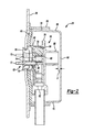
Figure 2 is a fragmentary section view of the compressor ofFigure 1 ; -
Figure 3 is an additional fragmentary section view of the compressor ofFigure 1 ; -
Figure 4 is a fragmentary section view of an alternate compressor according to the present disclosure; and -
Figure 5 is a fragmentary section view of an alternate compressor according to the present disclosure. - The following description is merely exemplary in nature and is not intended to limit the present disclosure, application, or uses. It should be understood that throughout the drawings, corresponding reference numerals indicate like or corresponding parts and features.
- The present teachings are suitable for incorporation in many different types of scroll and rotary compressors, including hermetic machines, open drive machines and non-hermetic machines. For exemplary purposes, a
compressor 10 is shown as a hermetic scroll refrigerant-compressor of the low-side type, i.e., where the motor and compressor are cooled by suction gas in the hermetic shell, as illustrated in the vertical section shown inFigure 1 . - With reference to
Figure 1 ,compressor 10 may include ahermetic shell assembly 12, a mainbearing housing assembly 14, amotor assembly 16, acompression mechanism 18, aseal assembly 20, arefrigerant discharge fitting 22, adischarge valve assembly 24, and aterminal assembly 26.Shell assembly 12 may house main bearinghousing assembly 14,motor assembly 16, andcompression mechanism 18. -
Shell assembly 12 may generally form a compressor housing and may include acylindrical shell 28, anend cap 30 at the upper end thereof, a transversely extendingpartition 32, and abase 34 at a lower end thereof. Endcap 30 andpartition 32 may generally define adischarge chamber 36.Discharge chamber 36 may generally form a discharge muffler forcompressor 10.Refrigerant discharge fitting 22 may be attached toshell assembly 12 at opening 38 inend cap 30.Discharge valve assembly 24 may be located within discharge fitting 22 and may generally prevent a reverse flow condition.Partition 32 may include adischarge passage 40 therethrough providing communication betweencompression mechanism 18 anddischarge chamber 36. - Main bearing
housing assembly 14 may be affixed toshell 28 at a plurality of points in any desirable manner, such as staking. Main bearinghousing assembly 14 may include a main bearinghousing 42.Motor assembly 16 may generally include amotor stator 44, arotor 46, and a drive shaft 48.Motor stator 44 may be press fit intoshell 28. Drive shaft 48 may be rotatably driven byrotor 46 and may extend through main bearinghousing 42. -
Compression mechanism 18 may generally include anorbiting scroll 50 and anon-orbiting scroll 52.Orbiting scroll 50 may be supported on main bearinghousing 42 and may be driven by drive shaft 48. An Oldhamcoupling 54 may be engaged with the orbiting andnon-orbiting scrolls scroll 52 may be rotationally secured to main bearinghousing 42 and may be axially displaceable relative to main bearinghousing 42 and orbitingscroll 50. -
Seal assembly 20 may include a floating seal engaged withpartition 32 and non-orbitingscroll 52.Seal assembly 20 may be axially displaceable relative toshell assembly 12 andnon-orbiting scroll 52 and may provide for axial displacement ofnon-orbiting scroll 52 while maintaining a sealed engagement withpartition 32 to isolate discharge and suction pressure regions ofcompressor 10 from one another. -
Terminal assembly 26 may be coupled toshell assembly 12 to provide electrical communication tocompressor 10 from an external source. With reference toFigures 2 and3 ,terminal assembly 26 may include amounting bracket 56, acover 58, agasket 60, aterminal block 62, and aplug 64.Mounting bracket 56 may be fixed toshell assembly 12, surrounding an opening 66housing terminal block 62.Cover 58 may be secured tobracket 56 in a variety of ways including a snap-fit engagement and may include arear wall 68 havingsidewalls 70 extending therefrom towardshell assembly 12.Gasket 60 may be formed from a compressible material such as a foam or an elastomer and may be located betweencover 58 andshell assembly 12. More specifically,gasket 60 may be formed from neoprene. The engagement betweenmounting bracket 56 andcover 58 may compressgasket 60 betweensidewalls 70 andshell assembly 12, forming a first sealing region. -
Terminal block 62 may includepins 72 havingceramic insulators 74, fusedglass insulators 75, andrubber boots 77 disposed thereon.Plug 64 may be engaged withpins 72. More specifically, plug 64 may include first andsecond portions First portion 76 may be housed withinsecond portion 78 and may definereceptacles 80 receivingpins 72 and providing electrical communication betweenpins 72 and awire 82. -
Second portion 78 may include afirst recess 84 on a first side and a protrusion 86 a second side. The first side may face theterminal block 62 and the second side may face thecover 58.First recess 84 may define awall 88 housingfirst portion 76. The engagement betweenpins 72 andreceptacles 80 may maintain an engagement betweenfirst portion 76 andgasket 60, causinggasket 60 to be compressed againstshell assembly 12 and forming a second sealing region. The engagement betweenpins 72 andreceptacles 80 may additionally causerubber boots 77 to abutfirst portion 76 forming a third sealing region. -
Protrusion 86 extends outward fromshell assembly 12 generally towardrear wall 68 ofcover 58. When pins 72 are fully installed withinreceptacles 80,protrusion 86 is spaced from rear wall 68 a distance (D). However, the spacing (D) betweenprotrusion 86 andrear wall 68 limits a disengagement betweenpins 72 andreceptacles 80. More specifically, the distance (D) may maintain at least a fifty percent engagement betweenpins 72 andreceptacles 80.Plug 64 may compress gasket 60 a distance greater than the distance (D) when fully engaged withpins 72. - In an alternate example seen in
Figure 4 ,protrusion 186 may define acavity 190 housing aresilient member 192, such as an elastomeric member. Themember 192 may abutprotrusion 186 andwall 168 ofcover 158 to maintain engagement ofplug 164 while limiting vibration transmission betweencover 158 and plug 164. - In an alternate example seen in
Figure 5 ,protrusion 286 may define acavity 290 housing apiston member 292 and a biasingmember 294. Themember 292 may be forced into contact withwall 268 by biasingmember 294. The engagement of biasingmember 294 withplug 264 andpiston member 292 may maintain engagement ofplug 264 while limiting vibration transmission betweencover 258 and plug 264.
Claims (11)
- A terminal assembly (26) for a compressor (10) having a motor (16) contained within a shell (28), the terminal assembly (26) comprising:a terminal block (62) fixable to the shell (28) for electrical communication with the motor (16) of said compressor (10);a cover (58, 158, 258) adapted to be secured relative to the shell (28); anda plug (64, 164, 264) engaged with the terminal block (62) and providing electrical communication between the terminal block (62) and a wire (82), said plug (64, 164, 264) including a first side facing the terminal block (62) and a second side facing a wall (68) of said cover (58, 158, 258), characterised by said second side including a protrusion (86, 186) adapted to extend toward said wall (68) and be spaced a distance (D) therefrom so as to limit a disengagement between pins (72) of said terminal block and said plug (64, 164, 264), wherein said protrusion is adapted to be spaced the distance (D) from said wall when said plug is fully engaged with said pins (72) of said terminal block.
- The terminal assembly (26) of claim 1, further comprising a resilient member (192, 292, 294) engaged with said protrusion (86, 186) and said wall (68, 168, 268) of said cover (58, 158, 258) to maintain engagement between said plug (64, 164, 264) and the terminal block (62) while limiting vibration transmission therebetween.
- The terminal assembly (26) of claim 2, wherein said protrusion (86, 186) defines a cavity (190, 290) facing said cover (58, 158, 258) and housing said resilient member (192, 292, 294) therein.
- The terminal assembly (26) of claim 3, wherein said resilient member (192, 292, 294) includes an elastomeric member (192) abutting said protrusion (86, 186) and said wall (68, 168, 268) of said cover (58, 158, 258).
- The terminal assembly (26) of claim 3, wherein said resilient member (192, 292, 294) includes a piston (292) and a biasing member (294) located within said cavity (190, 290) and urging said piston (292) against said wall (68, 168, 268) of said cover (58, 158, 258).
- The terminal assembly (26) of any one of claims 1 to 4, wherein said spacing providing at least 50 percent engagement between said pins (72) and said plug (64, 164, 264) when said plug (64, 164, 264) is displaced from full engagement with said pins (72) to a position where said protrusion (86, 186) abuts said wall (68, 168, 268).
- The terminal assembly (26) of any one of claims 1 to 6, further comprising a seal (60) surrounding said terminal block (62) and located between said plug (64, 164, 264) and said shell (28), said plug (64, 164, 264) biasing said seal (60) against said shell (28).
- The terminal assembly (26) of claim 7, wherein said plug (64, 164, 264) compresses said seal (60) a distance greater than the distance between the protrusion (86, 186) and the wall (68, 168, 268).
- The terminal assembly (26) of claim 7, wherein said cover (58, 158, 258) is engaged with said seal (60) and biases said seal (60) against said shell (28) at a location surrounding said plug (64, 164, 264).
- A compressor (10) comprising:a shell (28);a compression mechanism (18) supported within said shell (28);a motor (16) drivingly engaged with said compression mechanism (18); andthe terminal assembly (26) of any one of claims 1 to 6, wherein:said cover (58, 158, 258) is secured relative to said shell (28); and said terminal block (62) is fixed to said shell (28) and in electrical communication with said motor (16).
- The compressor (10) of claim 10, further comprising a mounting bracket (56) fixed to said shell (28) and having said cover (58, 158, 258) fixed thereto.
Applications Claiming Priority (2)
| Application Number | Priority Date | Filing Date | Title |
|---|---|---|---|
| US14360709P | 2009-01-09 | 2009-01-09 | |
| PCT/US2010/020478 WO2010080984A2 (en) | 2009-01-09 | 2010-01-08 | Compressor having terminal plug assembly |
Publications (3)
| Publication Number | Publication Date |
|---|---|
| EP2307731A2 EP2307731A2 (en) | 2011-04-13 |
| EP2307731A4 EP2307731A4 (en) | 2012-03-28 |
| EP2307731B1 true EP2307731B1 (en) | 2014-07-09 |
Family
ID=42317155
Family Applications (1)
| Application Number | Title | Priority Date | Filing Date |
|---|---|---|---|
| EP20100729558 Active EP2307731B1 (en) | 2009-01-09 | 2010-01-08 | Compressor having terminal plug assembly |
Country Status (5)
| Country | Link |
|---|---|
| US (1) | US9331420B2 (en) |
| EP (1) | EP2307731B1 (en) |
| CN (1) | CN102272455B (en) |
| MX (1) | MX2011007183A (en) |
| WO (1) | WO2010080984A2 (en) |
Families Citing this family (20)
| Publication number | Priority date | Publication date | Assignee | Title |
|---|---|---|---|---|
| US8721371B2 (en) * | 2011-05-27 | 2014-05-13 | Emerson Climate Technologies, Inc. | Conduit adaptor |
| FR2977407B1 (en) * | 2011-06-30 | 2013-07-05 | Valeo Japan Co Ltd | DEVICE FOR ELECTRICALLY CONNECTING AN ELECTRICAL COMPRESSOR |
| US8801400B2 (en) * | 2011-07-08 | 2014-08-12 | Danfoss Scroll Technologies Llc | Secure connection terminal for hermetic compressor |
| CN102352830B (en) | 2011-10-28 | 2014-06-18 | 黄石东贝电器股份有限公司 | Sealed compressor shell |
| CN103174623A (en) * | 2011-12-20 | 2013-06-26 | 卢海南 | Water-boiling type refrigeration compressor |
| JP5522184B2 (en) * | 2012-02-02 | 2014-06-18 | 株式会社豊田自動織機 | Electric compressor and its airtightness inspection method |
| US9480177B2 (en) | 2012-07-27 | 2016-10-25 | Emerson Climate Technologies, Inc. | Compressor protection module |
| US9634538B2 (en) * | 2013-07-31 | 2017-04-25 | Trane International Inc. | Terminal assembly for refrigeration compressor |
| JP2015117690A (en) * | 2013-11-14 | 2015-06-25 | 三星電子株式会社Samsung Electronics Co.,Ltd. | Protective cover and compressor using the same |
| US9851131B2 (en) * | 2013-11-14 | 2017-12-26 | Samsung Electronics Co., Ltd. | Compressor and air conditioner having the same |
| CN104847620B (en) * | 2015-04-28 | 2017-10-10 | 胡金花 | Automobile electric fuel pump |
| US10693258B2 (en) * | 2016-11-22 | 2020-06-23 | Ebara Corporation | Submersible motor and waterproof connector |
| JP6583367B2 (en) * | 2017-08-21 | 2019-10-02 | ダイキン工業株式会社 | Hermetic compressor |
| JP6881378B2 (en) * | 2018-03-30 | 2021-06-02 | 株式会社豊田自動織機 | Electric compressor |
| DE102019107520A1 (en) * | 2018-04-26 | 2019-10-31 | Hanon Systems | Apparatus for driving a compressor and method of mounting the apparatus |
| WO2019216834A1 (en) * | 2018-05-07 | 2019-11-14 | Siam Compressor Industry Co., Ltd. | Power supply wire connecting structure for hermetic compressor |
| JP6652158B2 (en) * | 2018-07-09 | 2020-02-19 | ダイキン工業株式会社 | Compressor |
| FR3147666B1 (en) * | 2023-04-06 | 2026-03-13 | Psa Automobiles Sa | compressor for an automotive air conditioning system |
| CN119009841A (en) * | 2023-05-16 | 2024-11-22 | 南昌海立电器有限公司 | Junction box and compressor |
| JP2025087055A (en) * | 2023-11-29 | 2025-06-10 | パナソニックIpマネジメント株式会社 | Sealed structure, compressor equipped with sealed structure, refrigeration cycle device equipped with compressor, and terminal cover |
Family Cites Families (19)
| Publication number | Priority date | Publication date | Assignee | Title |
|---|---|---|---|---|
| US1635507A (en) * | 1926-11-04 | 1927-07-12 | Edward T Seasock | Attachment for electric extension plugs |
| US3160460A (en) * | 1962-01-17 | 1964-12-08 | Fusite Corp | Terminal assembly having conductor pins and connector block |
| US4512724A (en) * | 1983-03-17 | 1985-04-23 | Metaframe, Inc. | Electric pump for use in filtering system of a tropical fish tank or the like |
| US4699592A (en) * | 1985-06-04 | 1987-10-13 | Telcor, Inc. | Rotatable connector |
| JPH0754932Y2 (en) * | 1990-07-09 | 1995-12-18 | 矢崎総業株式会社 | Waterproof structure of screw tightened connector |
| US4998035A (en) * | 1990-07-26 | 1991-03-05 | American Standard Inc. | Method for attaching a motor lead restraint device to a compressor pump |
| JPH0617781A (en) * | 1991-06-21 | 1994-01-25 | Hitachi Ltd | Horizontal scroll compressor |
| US5199898A (en) * | 1991-09-23 | 1993-04-06 | Tecumseh Products Company | External terminal shield |
| US5249899A (en) * | 1992-10-28 | 1993-10-05 | Wilson Robert L | Head bolt and driver therefore |
| JP3241994B2 (en) * | 1995-07-03 | 2001-12-25 | 株式会社荏原製作所 | Underwater motor and waterproof connector |
| US5980222A (en) * | 1997-11-13 | 1999-11-09 | Tecumseh Products Company | Hermetic reciprocating compressor having a housing divided into a low pressure portion and a high pressure portion |
| US6379162B1 (en) * | 2000-07-27 | 2002-04-30 | Delphi Technologies, Inc. | Electrical connector system |
| JP2002276550A (en) * | 2001-03-14 | 2002-09-25 | Matsushita Electric Ind Co Ltd | Method for connecting compressor with built-in motor to external wiring, connectors used for the same, compressor with built-in motor using them |
| BR0104134A (en) * | 2001-07-30 | 2003-08-05 | Brasil Compressores Sa | Electrical connector for hermetic compressor motor and its obtaining process |
| US7059839B2 (en) * | 2002-12-10 | 2006-06-13 | Tecumseh Products Company | Horizontal compressor end cap with a terminal, a visually transparent member, and a heater well mounted on the end cap projection |
| CN1611781A (en) * | 2003-10-30 | 2005-05-04 | 乐金电子(天津)电器有限公司 | Rotary compressor |
| JP2006183655A (en) * | 2004-10-14 | 2006-07-13 | Matsushita Electric Ind Co Ltd | Compressor and refrigeration equipment and refrigerator |
| WO2006129448A1 (en) * | 2005-05-30 | 2006-12-07 | Sanden Corporation | Electric compressor |
| JP2008169754A (en) * | 2007-01-11 | 2008-07-24 | Daikin Ind Ltd | Compressor |
-
2010
- 2010-01-08 WO PCT/US2010/020478 patent/WO2010080984A2/en not_active Ceased
- 2010-01-08 CN CN201080004242.8A patent/CN102272455B/en active Active
- 2010-01-08 MX MX2011007183A patent/MX2011007183A/en active IP Right Grant
- 2010-01-08 US US12/684,386 patent/US9331420B2/en active Active
- 2010-01-08 EP EP20100729558 patent/EP2307731B1/en active Active
Also Published As
| Publication number | Publication date |
|---|---|
| US20100196175A1 (en) | 2010-08-05 |
| EP2307731A2 (en) | 2011-04-13 |
| WO2010080984A3 (en) | 2010-10-21 |
| WO2010080984A2 (en) | 2010-07-15 |
| MX2011007183A (en) | 2011-08-03 |
| EP2307731A4 (en) | 2012-03-28 |
| CN102272455A (en) | 2011-12-07 |
| US9331420B2 (en) | 2016-05-03 |
| CN102272455B (en) | 2015-02-25 |
Similar Documents
| Publication | Publication Date | Title |
|---|---|---|
| US9331420B2 (en) | Compressor having terminal plug assembly | |
| EP0479421B1 (en) | Scroll machine with floating seal | |
| US8043078B2 (en) | Compressor sealing arrangement | |
| US5156539A (en) | Scroll machine with floating seal | |
| US7717687B2 (en) | Scroll compressor with compliant retainer | |
| EP3263900B1 (en) | Scroll-type compressor | |
| WO2009035640A1 (en) | Compressor sealing arrangement | |
| CN108474475B (en) | Sealing structure of airtight container, and vehicle refrigerant compressor having the same | |
| JP5691352B2 (en) | Scroll compressor | |
| CN109844318B (en) | Scroll compressor having a plurality of scroll members | |
| KR102693523B1 (en) | electric compressor | |
| CN101319672B (en) | Cyclone compressor | |
| US8033803B2 (en) | Compressor having improved sealing assembly | |
| EP0400951B1 (en) | Axial sealing mechanism for a scroll type compressor | |
| WO2006129448A1 (en) | Electric compressor | |
| US20040115063A1 (en) | Scroll compressor | |
| CN204267285U (en) | Scroll compressor | |
| CN101346547B (en) | Electric compressor | |
| EP1867874B1 (en) | Electric motor-driven compressor | |
| EP2221477A1 (en) | Electric compressor terminal device | |
| KR100348609B1 (en) | Suction and discharge pressure separation structure for scroll compressor | |
| KR102522649B1 (en) | Scroll compressor | |
| EP0373876B1 (en) | Hermetically sealed scroll type refrigerant compressor | |
| EP2781752B1 (en) | Scroll compressor having a scroll support and/or movement limiter | |
| KR100608868B1 (en) | Assembly structure of scroll compressor |
Legal Events
| Date | Code | Title | Description |
|---|---|---|---|
| PUAI | Public reference made under article 153(3) epc to a published international application that has entered the european phase |
Free format text: ORIGINAL CODE: 0009012 |
|
| 17P | Request for examination filed |
Effective date: 20101221 |
|
| AK | Designated contracting states |
Kind code of ref document: A2 Designated state(s): AT BE BG CH CY CZ DE DK EE ES FI FR GB GR HR HU IE IS IT LI LT LU LV MC MK MT NL NO PL PT RO SE SI SK SM TR |
|
| AX | Request for extension of the european patent |
Extension state: AL BA RS |
|
| RIN1 | Information on inventor provided before grant (corrected) |
Inventor name: HEIDECKER, MATTHEW, J. Inventor name: HEMMELGARN, GREGG, M. Inventor name: BEDELL, RICK, T. |
|
| A4 | Supplementary search report drawn up and despatched |
Effective date: 20120228 |
|
| RIC1 | Information provided on ipc code assigned before grant |
Ipc: H01R 13/52 20060101ALI20120222BHEP Ipc: F25B 31/02 20060101ALI20120222BHEP Ipc: F04C 23/00 20060101ALI20120222BHEP Ipc: F04B 39/06 20060101ALI20120222BHEP Ipc: H01R 13/00 20060101ALI20120222BHEP Ipc: F04C 18/02 20060101AFI20120222BHEP Ipc: F04B 39/12 20060101ALI20120222BHEP Ipc: F04C 29/00 20060101ALI20120222BHEP |
|
| DAX | Request for extension of the european patent (deleted) | ||
| 17Q | First examination report despatched |
Effective date: 20130109 |
|
| GRAP | Despatch of communication of intention to grant a patent |
Free format text: ORIGINAL CODE: EPIDOSNIGR1 |
|
| INTG | Intention to grant announced |
Effective date: 20140123 |
|
| GRAS | Grant fee paid |
Free format text: ORIGINAL CODE: EPIDOSNIGR3 |
|
| GRAA | (expected) grant |
Free format text: ORIGINAL CODE: 0009210 |
|
| AK | Designated contracting states |
Kind code of ref document: B1 Designated state(s): AT BE BG CH CY CZ DE DK EE ES FI FR GB GR HR HU IE IS IT LI LT LU LV MC MK MT NL NO PL PT RO SE SI SK SM TR |
|
| REG | Reference to a national code |
Ref country code: GB Ref legal event code: FG4D |
|
| REG | Reference to a national code |
Ref country code: CH Ref legal event code: EP Ref country code: AT Ref legal event code: REF Ref document number: 676684 Country of ref document: AT Kind code of ref document: T Effective date: 20140715 |
|
| REG | Reference to a national code |
Ref country code: IE Ref legal event code: FG4D |
|
| REG | Reference to a national code |
Ref country code: DE Ref legal event code: R096 Ref document number: 602010017361 Country of ref document: DE Effective date: 20140821 |
|
| REG | Reference to a national code |
Ref country code: AT Ref legal event code: MK05 Ref document number: 676684 Country of ref document: AT Kind code of ref document: T Effective date: 20140709 |
|
| REG | Reference to a national code |
Ref country code: NL Ref legal event code: VDEP Effective date: 20140709 |
|
| REG | Reference to a national code |
Ref country code: LT Ref legal event code: MG4D |
|
| PG25 | Lapsed in a contracting state [announced via postgrant information from national office to epo] |
Ref country code: GR Free format text: LAPSE BECAUSE OF FAILURE TO SUBMIT A TRANSLATION OF THE DESCRIPTION OR TO PAY THE FEE WITHIN THE PRESCRIBED TIME-LIMIT Effective date: 20141010 Ref country code: FI Free format text: LAPSE BECAUSE OF FAILURE TO SUBMIT A TRANSLATION OF THE DESCRIPTION OR TO PAY THE FEE WITHIN THE PRESCRIBED TIME-LIMIT Effective date: 20140709 Ref country code: PT Free format text: LAPSE BECAUSE OF FAILURE TO SUBMIT A TRANSLATION OF THE DESCRIPTION OR TO PAY THE FEE WITHIN THE PRESCRIBED TIME-LIMIT Effective date: 20141110 Ref country code: NO Free format text: LAPSE BECAUSE OF FAILURE TO SUBMIT A TRANSLATION OF THE DESCRIPTION OR TO PAY THE FEE WITHIN THE PRESCRIBED TIME-LIMIT Effective date: 20141009 Ref country code: BG Free format text: LAPSE BECAUSE OF FAILURE TO SUBMIT A TRANSLATION OF THE DESCRIPTION OR TO PAY THE FEE WITHIN THE PRESCRIBED TIME-LIMIT Effective date: 20141009 Ref country code: ES Free format text: LAPSE BECAUSE OF FAILURE TO SUBMIT A TRANSLATION OF THE DESCRIPTION OR TO PAY THE FEE WITHIN THE PRESCRIBED TIME-LIMIT Effective date: 20140709 Ref country code: SE Free format text: LAPSE BECAUSE OF FAILURE TO SUBMIT A TRANSLATION OF THE DESCRIPTION OR TO PAY THE FEE WITHIN THE PRESCRIBED TIME-LIMIT Effective date: 20140709 Ref country code: LT Free format text: LAPSE BECAUSE OF FAILURE TO SUBMIT A TRANSLATION OF THE DESCRIPTION OR TO PAY THE FEE WITHIN THE PRESCRIBED TIME-LIMIT Effective date: 20140709 |
|
| PG25 | Lapsed in a contracting state [announced via postgrant information from national office to epo] |
Ref country code: HR Free format text: LAPSE BECAUSE OF FAILURE TO SUBMIT A TRANSLATION OF THE DESCRIPTION OR TO PAY THE FEE WITHIN THE PRESCRIBED TIME-LIMIT Effective date: 20140709 Ref country code: AT Free format text: LAPSE BECAUSE OF FAILURE TO SUBMIT A TRANSLATION OF THE DESCRIPTION OR TO PAY THE FEE WITHIN THE PRESCRIBED TIME-LIMIT Effective date: 20140709 Ref country code: NL Free format text: LAPSE BECAUSE OF FAILURE TO SUBMIT A TRANSLATION OF THE DESCRIPTION OR TO PAY THE FEE WITHIN THE PRESCRIBED TIME-LIMIT Effective date: 20140709 Ref country code: IS Free format text: LAPSE BECAUSE OF FAILURE TO SUBMIT A TRANSLATION OF THE DESCRIPTION OR TO PAY THE FEE WITHIN THE PRESCRIBED TIME-LIMIT Effective date: 20141109 Ref country code: PL Free format text: LAPSE BECAUSE OF FAILURE TO SUBMIT A TRANSLATION OF THE DESCRIPTION OR TO PAY THE FEE WITHIN THE PRESCRIBED TIME-LIMIT Effective date: 20140709 Ref country code: LV Free format text: LAPSE BECAUSE OF FAILURE TO SUBMIT A TRANSLATION OF THE DESCRIPTION OR TO PAY THE FEE WITHIN THE PRESCRIBED TIME-LIMIT Effective date: 20140709 Ref country code: CY Free format text: LAPSE BECAUSE OF FAILURE TO SUBMIT A TRANSLATION OF THE DESCRIPTION OR TO PAY THE FEE WITHIN THE PRESCRIBED TIME-LIMIT Effective date: 20140709 |
|
| REG | Reference to a national code |
Ref country code: DE Ref legal event code: R097 Ref document number: 602010017361 Country of ref document: DE |
|
| PG25 | Lapsed in a contracting state [announced via postgrant information from national office to epo] |
Ref country code: SK Free format text: LAPSE BECAUSE OF FAILURE TO SUBMIT A TRANSLATION OF THE DESCRIPTION OR TO PAY THE FEE WITHIN THE PRESCRIBED TIME-LIMIT Effective date: 20140709 Ref country code: CZ Free format text: LAPSE BECAUSE OF FAILURE TO SUBMIT A TRANSLATION OF THE DESCRIPTION OR TO PAY THE FEE WITHIN THE PRESCRIBED TIME-LIMIT Effective date: 20140709 Ref country code: IT Free format text: LAPSE BECAUSE OF FAILURE TO SUBMIT A TRANSLATION OF THE DESCRIPTION OR TO PAY THE FEE WITHIN THE PRESCRIBED TIME-LIMIT Effective date: 20140709 Ref country code: RO Free format text: LAPSE BECAUSE OF FAILURE TO SUBMIT A TRANSLATION OF THE DESCRIPTION OR TO PAY THE FEE WITHIN THE PRESCRIBED TIME-LIMIT Effective date: 20140709 Ref country code: DK Free format text: LAPSE BECAUSE OF FAILURE TO SUBMIT A TRANSLATION OF THE DESCRIPTION OR TO PAY THE FEE WITHIN THE PRESCRIBED TIME-LIMIT Effective date: 20140709 Ref country code: EE Free format text: LAPSE BECAUSE OF FAILURE TO SUBMIT A TRANSLATION OF THE DESCRIPTION OR TO PAY THE FEE WITHIN THE PRESCRIBED TIME-LIMIT Effective date: 20140709 |
|
| PLBE | No opposition filed within time limit |
Free format text: ORIGINAL CODE: 0009261 |
|
| STAA | Information on the status of an ep patent application or granted ep patent |
Free format text: STATUS: NO OPPOSITION FILED WITHIN TIME LIMIT |
|
| 26N | No opposition filed |
Effective date: 20150410 |
|
| PG25 | Lapsed in a contracting state [announced via postgrant information from national office to epo] |
Ref country code: BE Free format text: LAPSE BECAUSE OF NON-PAYMENT OF DUE FEES Effective date: 20150131 |
|
| REG | Reference to a national code |
Ref country code: CH Ref legal event code: PL |
|
| PG25 | Lapsed in a contracting state [announced via postgrant information from national office to epo] |
Ref country code: LU Free format text: LAPSE BECAUSE OF FAILURE TO SUBMIT A TRANSLATION OF THE DESCRIPTION OR TO PAY THE FEE WITHIN THE PRESCRIBED TIME-LIMIT Effective date: 20150108 |
|
| GBPC | Gb: european patent ceased through non-payment of renewal fee |
Effective date: 20150108 |
|
| PG25 | Lapsed in a contracting state [announced via postgrant information from national office to epo] |
Ref country code: MC Free format text: LAPSE BECAUSE OF FAILURE TO SUBMIT A TRANSLATION OF THE DESCRIPTION OR TO PAY THE FEE WITHIN THE PRESCRIBED TIME-LIMIT Effective date: 20140709 |
|
| PG25 | Lapsed in a contracting state [announced via postgrant information from national office to epo] |
Ref country code: CH Free format text: LAPSE BECAUSE OF NON-PAYMENT OF DUE FEES Effective date: 20150131 Ref country code: GB Free format text: LAPSE BECAUSE OF NON-PAYMENT OF DUE FEES Effective date: 20150108 Ref country code: LI Free format text: LAPSE BECAUSE OF NON-PAYMENT OF DUE FEES Effective date: 20150131 |
|
| REG | Reference to a national code |
Ref country code: IE Ref legal event code: MM4A |
|
| PG25 | Lapsed in a contracting state [announced via postgrant information from national office to epo] |
Ref country code: SI Free format text: LAPSE BECAUSE OF FAILURE TO SUBMIT A TRANSLATION OF THE DESCRIPTION OR TO PAY THE FEE WITHIN THE PRESCRIBED TIME-LIMIT Effective date: 20140709 |
|
| REG | Reference to a national code |
Ref country code: FR Ref legal event code: PLFP Year of fee payment: 7 |
|
| PG25 | Lapsed in a contracting state [announced via postgrant information from national office to epo] |
Ref country code: IE Free format text: LAPSE BECAUSE OF NON-PAYMENT OF DUE FEES Effective date: 20150108 |
|
| PG25 | Lapsed in a contracting state [announced via postgrant information from national office to epo] |
Ref country code: BE Free format text: LAPSE BECAUSE OF FAILURE TO SUBMIT A TRANSLATION OF THE DESCRIPTION OR TO PAY THE FEE WITHIN THE PRESCRIBED TIME-LIMIT Effective date: 20140709 |
|
| PG25 | Lapsed in a contracting state [announced via postgrant information from national office to epo] |
Ref country code: MT Free format text: LAPSE BECAUSE OF FAILURE TO SUBMIT A TRANSLATION OF THE DESCRIPTION OR TO PAY THE FEE WITHIN THE PRESCRIBED TIME-LIMIT Effective date: 20140709 |
|
| REG | Reference to a national code |
Ref country code: FR Ref legal event code: PLFP Year of fee payment: 8 |
|
| PG25 | Lapsed in a contracting state [announced via postgrant information from national office to epo] |
Ref country code: HU Free format text: LAPSE BECAUSE OF FAILURE TO SUBMIT A TRANSLATION OF THE DESCRIPTION OR TO PAY THE FEE WITHIN THE PRESCRIBED TIME-LIMIT; INVALID AB INITIO Effective date: 20100108 Ref country code: SM Free format text: LAPSE BECAUSE OF FAILURE TO SUBMIT A TRANSLATION OF THE DESCRIPTION OR TO PAY THE FEE WITHIN THE PRESCRIBED TIME-LIMIT Effective date: 20140709 |
|
| PG25 | Lapsed in a contracting state [announced via postgrant information from national office to epo] |
Ref country code: TR Free format text: LAPSE BECAUSE OF FAILURE TO SUBMIT A TRANSLATION OF THE DESCRIPTION OR TO PAY THE FEE WITHIN THE PRESCRIBED TIME-LIMIT Effective date: 20140709 |
|
| REG | Reference to a national code |
Ref country code: FR Ref legal event code: PLFP Year of fee payment: 9 |
|
| PG25 | Lapsed in a contracting state [announced via postgrant information from national office to epo] |
Ref country code: MK Free format text: LAPSE BECAUSE OF FAILURE TO SUBMIT A TRANSLATION OF THE DESCRIPTION OR TO PAY THE FEE WITHIN THE PRESCRIBED TIME-LIMIT Effective date: 20140709 |
|
| PGFP | Annual fee paid to national office [announced via postgrant information from national office to epo] |
Ref country code: FR Payment date: 20241219 Year of fee payment: 16 |
|
| PGFP | Annual fee paid to national office [announced via postgrant information from national office to epo] |
Ref country code: DE Payment date: 20251217 Year of fee payment: 17 |