EP2307254B1 - Luftfedersystem für ein schienenfahrzeug - Google Patents
Luftfedersystem für ein schienenfahrzeug Download PDFInfo
- Publication number
- EP2307254B1 EP2307254B1 EP09780865.3A EP09780865A EP2307254B1 EP 2307254 B1 EP2307254 B1 EP 2307254B1 EP 09780865 A EP09780865 A EP 09780865A EP 2307254 B1 EP2307254 B1 EP 2307254B1
- Authority
- EP
- European Patent Office
- Prior art keywords
- cylinder
- pressure
- suspension system
- control
- air suspension
- Prior art date
- Legal status (The legal status is an assumption and is not a legal conclusion. Google has not performed a legal analysis and makes no representation as to the accuracy of the status listed.)
- Active
Links
Images

Classifications
-
- B—PERFORMING OPERATIONS; TRANSPORTING
- B61—RAILWAYS
- B61F—RAIL VEHICLE SUSPENSIONS, e.g. UNDERFRAMES, BOGIES OR ARRANGEMENTS OF WHEEL AXLES; RAIL VEHICLES FOR USE ON TRACKS OF DIFFERENT WIDTH; PREVENTING DERAILING OF RAIL VEHICLES; WHEEL GUARDS, OBSTRUCTION REMOVERS OR THE LIKE FOR RAIL VEHICLES
- B61F5/00—Constructional details of bogies; Connections between bogies and vehicle underframes; Arrangements or devices for adjusting or allowing self-adjustment of wheel axles or bogies when rounding curves
- B61F5/02—Arrangements permitting limited transverse relative movements between vehicle underframe or bolster and bogie; Connections between underframes and bogies
- B61F5/14—Side bearings
Definitions
- Such an air spring system is from the EP 0 175 108 A2 already known.
- the illustrated suspension of a rail vehicle for passenger transport comprises a compensating or overflow valve, which is arranged between two air springs and pneumatically connected thereto.
- the balancing valve has two opposing check valves, which connect the air springs with too much pressure difference between the air pressures.
- a mechanism is provided which permanently connects the two air springs, if one of the air springs was destroyed, for example, as a result of a crack.
- rail vehicles are known from practice, which have a mechanically ausgestaltetes primary spring system and a secondary air spring system.
- the air suspension system allows not only the additional damping and a level control of the car body to compensate for different loads through which the air springs are compressed to different degrees.
- the air springs are supplied with compressed air via a compressed air supply system, whereby the air springs can be ventilated by means of the compressed air supply system for level control of the vehicle bodies sprung by the air spring system.
- the air spring system generally has compensation devices which are intended to prevent the exceeding of a pressure difference threshold value between air springs connected to the compensation device.
- one of the check valves establishes a connection between the two control connections, so that the air spring with the higher pressure vented into the other air spring with the lower pressure or vented through the air spring in the event of a burst air spring bellows.
- balancing devices can not safely avoid safety-related misalignments of the car body.
- the invention is based on the above-mentioned air spring system, the task of particularly reliably to prevent the exceeding of a pressure difference threshold between connected to the balancing air springs.
- the invention solves this problem by the compensation device has at least one connected to the environment of the rail vehicle as a pressure sink outlet and connect the switching means acted upon by a higher pressure control port in the case of pressure equalization through the equalizer with at least one outlet.
- At least one air spring is vented into a pressure sink and not as in the prior art by establishing a running through the balancing device connection between the first and the second control port.
- the connection between the air spring to be vented and the pressure sink via a control port of the compensation device, the compensation device itself and the departure of the compensation device.
- At the control port which is acted upon by the smaller control pressure, however, occur no pressure changes. This results in no unnecessary interruptions of the venting process by the switching means as in the prior art, so that exceeding a pressure difference threshold value between the air springs is reliably avoided.
- the control connections of the compensation device are connected, for example, to a plurality of air springs via a selection unit, wherein the selection unit switches through the respective largest of the pressures provided by the air springs to the control connection.
- the control connections can also be connected to only one air spring. It can be provided that the air springs connected to the first control connection are arranged on one side of a bogie and the air springs connected to the second control connection are arranged on the opposite side of the bogie.
- the air springs can also be arranged in other ways on the rail vehicle. It is only important here that too great a pressure difference between the air springs is undesirable, for example due to a thereby caused Loss of the over the air springs cushioned car body.
- the compressed air supply system is used for compressed air control and / or regulation of the air springs, for example, to adjust the level of a car body to the height of a platform or to adjust while driving a desired damping behavior of the air springs.
- the compensation device has switching means which can be switched by means of the pressure difference applied to the two control terminals.
- switching means which can be switched by means of the pressure difference applied to the two control terminals.
- the switching means changes into a switching position which de-aerates the switching port subjected to a higher pressure.
- the switching process can also be effected by other or additional control parameters.
- the switching means may for example be designed such that they can be blocked by means of a blocking device, which prevents venting in a repair case on the balancing device.
- the pressure difference threshold value can be adjustable, for example by means of an adjustment device provided for this purpose on the compensation device. If an imbalance of the car body is to be avoided by means of the compensating device, the threshold value is to be selected such that, if it is exceeded, a safety-critical imbalance of the car body or a torsion damaging the car body can be assumed.
- the pressure sink is the environment of the rail vehicle.
- the at least one outlet of the compensation device can be connected, for example, directly or via a pneumatic connecting line with the environment of the rail vehicle.
- the switching means are two cylinder pistons movably mounted in a cylinder and biased by biasing means, which are held by the biasing means in a closed position and in a switching position effecting pressure equalization between the first and second control ports one of the two control pistons displaced out of the closed position and displaced counter to the biasing means releases a connection passing through the compensating device between an outlet and the control connection subjected to the greater pressure.
- the cylinder pistons movably mounted in a cylinder can be switched on both sides with pressure and thus by means of a pressure difference.
- This constructed of cylinder and cylinder piston switching means has a particularly simple and robust construction. They also offer the possibility, depending on the position of the cylinder piston in the cylinder to take a variety of switching positions.
- a cylinder in each case a cylinder is interposed with one of the two cylinder pistons in two lines connecting the first and the second control connection, wherein the one line piece carries at its end a sealing seat projecting into the one cylinder end, on which the cylinder piston is pressed in the closed position by the biasing means, and in the other cylinder end the other line piece opens, wherein the cylinder piston the cylinder in pneumatically separated Divided areas and in the sealing seat comprehensive cylinder area opens a line connected to a pressure sink.
- the two cylinder pistons are thus arranged in opposite directions, so that a control connection presses on the one hand via a sealed with a sealing piece of pipe against the biasing force on an end face of a cylinder piston and acts on the other line in the same direction as the biasing force on a rear side of the other cylinder piston.
- a control connection presses on the one hand via a sealed with a sealing piece of pipe against the biasing force on an end face of a cylinder piston and acts on the other line in the same direction as the biasing force on a rear side of the other cylinder piston.
- the one of the two cylinder piston is moved away from the sealing seat and releases a connection between the outlet and the control port with the higher pressure.
- the biasing means is a spring.
- the spring may be, for example, a coil spring.
- biasing force acting on the cylinder pistons by the biasing means is adjustable.
- the biasing force can be manually adjustable on the compensation device.
- a spring as a biasing means, for example by positional shift of a spring supporting abutment. This allows adjustment of the pressure difference threshold.
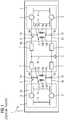
- FIG. 1 shows a rail vehicle 1 with a pneumatic spring system according to the prior art from a bird's eye view in a schematic representation.
- a car body 3 of the rail vehicle is mounted on two bogies 2, wherein the bogies have two wheel axles 4 and between the wheel axles 4 on each of the two sides of the rail vehicle two air springs 5.
- the air springs are based on the one hand on the bogie 2 and extend to the car body 3.
- Each of the air springs 5 is connected via a pneumatic line 6a with its associated air spring valve 7 in connection, each air spring valve 7 via a pneumatic Line 6b is in communication with a common compressed air source 8.
- a balancing device 12 is interposed and connected to a first control port 10a to the connecting line piece 9a and with a second control port 10b to the connecting line piece 9b.
- Two internal connection lines 13a, 13b extend from the first control connection 10a within the compensation device 12 as far as the second control connection 10b, one check valve 14a, 14b in each case being arranged in the internal connection lines 13a, 13b.
- the check valves 14a, 14b arranged in the internal connection lines 13a, 13b are arranged in opposite directions.
- the air springs 5 are supplied via the compressed air supply system 7, 8, 6a, 6b with compressed air.
- the pressure is regulated by ventilating or venting the air springs via the associated air spring valve 7, for which purpose a control and / or regulating system, not shown, controls the air spring valves 7 connected to the compressed air source 8.
- a pressure difference between air springs for example between the opposite air springs 5 of a bogie 2, can lead to a tilted position of the car body 3 or to a torsion of the car body 3.
- the pressure difference can be controlled by regulating the air spring valves 7 or be caused by a defective air spring valve 7 or caused by leakage in one of the air springs 5.
- the at least one compensation device 12 is arranged to reduce such safety-critical pressure differences.
- the pressure reduction takes place in a period of time, which is influenced by a variety of parameters such as the size of the leakage and / or the cross sections of the connecting line pieces 9a, 9b and uncontrollable, since the overflowing air, the control pressures on the balancing devices in interaction changed with the mentioned parameters. Exceeding a safety-critical pressure difference between air springs 5 can not be safely excluded in this prior art.
- FIG. 2 shows a rail vehicle 15 with an inventive air spring system according to a first embodiment of the bird's eye view in a schematic representation.
- the rail vehicle 15 differs from the rail vehicle 1 of FIG. 1 by a compensation device 16 with respect to the compensation device 12 of FIG. 1 changed structure.
- the balancer 16 is as well as the balancer 12 of FIG. 1 with a first control port 17a with an air spring 5 and with a second one Control terminal 17b connected to another air spring 5 and also has switching means 19 which are switchable by means of the applied to the two control terminals 17a, 17b pressure difference.
- the compensation device 16 has two outlets 18a, 18b connected to a pressure sink 20, and the switching means 19 are designed in such a way that, to reduce a pressure difference exceeding a pressure difference threshold, the switching means controls the control connection acted upon by a higher pressure 17a, 17b through the balancer 16 through with one of the outlets 18a, 18b connect.
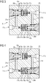
- FIG. 3 shows a schematic sectional view of an embodiment of a compensation device 16 'according to the invention.
- the balancing device 16 ' has a first control connection 17a and a second control connection 17b and two connecting lines 21a, 21b connecting the two control connections and passing through the balancing device.
- the connecting lines 21a, 21b in each case one in a cylinder 22a, 22b movably mounted and biased by a spring 24a, 24b cylinder piston 23a, 23b is arranged.
- the connecting line 21a extends from the control port 17a starting up to the cylinder 22a, the up to reaching here enough line piece 21a at its end a projecting into the cylinder end sealing seat 25a, on which the cylinder piston 23a in the closed position by the Spring 24a is pressed. Starting from the opposite cylinder end, the remaining half of the connecting line 21a extends to the second control port 17b.
- the other connecting line 21b wherein in this the cylinder 22b and cylinder piston 23b is arranged in opposite directions, so that the outgoing from the second control port 17b Line piece 21b extends to a sealed by the cylinder piston 23b sealing seat 25b.
- the cylinder pistons 23a, 23b subdivide the cylinders 22a, 22b into two pneumatically separated regions, wherein in the region comprising the sealing seat 25a, 25b, a line piece 26a, 26b connected to an outlet 18a, 18b opens.
- FIG. 4 shows a schematic sectional view of in FIG. 3 illustrated balancing device 16 'in a different switching position.
- the cylinder piston 23a, 23b in a pressure equalization between the first 17a and the second control port 17b causing switching position.
- the cylinder piston 23a is detached from the sealing seat 25a by means of a control pressure applied to the control port 17a and releases a pneumatic connection between the first control port 17a and the outlet 18a.
- the control pressure applied to the control port 17a must be greater than the sum of the biasing force divided by the seal seat surface and the control pressure applied to the second control port 17b.
Landscapes
- Engineering & Computer Science (AREA)
- Mechanical Engineering (AREA)
- Vehicle Body Suspensions (AREA)
Description
- Die Erfindung betrifft ein Luftfedersystem für ein Schienenfahrzeug mit
- mindestens zwei Luftfedern,
- einem Druckluft-Versorgungssystems zur Versorgung der Luftfedern mit Druckluft,
- und mindestens einer Ausgleichseinrichtung zum Abbau eines Druckunterschiedes zwischen Luftfedern,
- wobei die Ausgleichseinrichtung mindestens einen ersten mit wenigstens einer der Luftfedern verbundenen und einen zweiten mit wenigstens einer anderen Luftfeder verbundenen Steuer-Anschluss aufweist,
- und Schaltmittel, die mittels der an den beiden Steuer-Anschlüssen anliegenden Druckdifferenz schaltbar sind und in wenigstens einer Schaltposition einen Druckausgleich zwischen dem ersten und dem zweiten Steuer-Anschluss bewirken.
- Ein solches Luftfedersystem ist aus der
EP 0 175 108 A2 bereits bekannt. Die dort dargestellte Federung eines Schienenfahrzeugs zur Personenbeförderung umfasst ein Ausgleichs- oder Überstromventil, das zwischen zwei Luftfedern angeordnet und pneumatisch mit diesen verbunden ist. Das Ausgleichsventil verfügt über zwei einander gegenüberliegende Rückschlagventile, die bei einem zu großen Druckunterschied zwischen den Luftdrücken die Luftfedern miteinander verbinden. Ferner ist ein Mechanismus vorgesehen, der die beiden Luftfedern dauerhaft miteinander verbindet, wenn eine der Luftfedern beispielsweise in Folge eines Risses zerstört wurde. Weiterhin sind aus der Praxis Schienenfahrzeuge bekannt, die ein mechanisch ausgestaltetes Primärfedersystem und ein sekundäres Luftfedersystem aufweisen. Das Luftfedersystem ermöglicht neben der zusätzlichen Dämpfung auch eine Niveauregulierung des Wagenkastens zum Ausgleich unterschiedlicher Lasten, durch welche die Luftfedern unterschiedlich stark zusammengedrückt werden. Die Luftfedern werden über ein Druckluftversorgungssystem mit Druckluft versorgt, wobei zur Niveauregulierung der von dem Luftfedersystem gefederten Wagenkästen die Luftfedern mittels des Druckluftversorgungssystems be- und entlüftbar sind. Das Luftfedersystem weist zudem in der Regel Ausgleichseinrichtungen auf, welche das Überschreiten einer Druckunterschied-Schwellwertes zwischen an die Ausgleichseinrichtung angeschlossenen Luftfedern verhindern sollen. Hierzu weisen die aus dem Stand der Technik bekannten Ausgleichseinrichtungen einen jeweils mit einer Luftfeder verbundenen ersten und zweiten Steuer-Anschluss und zwei Rückschlagventile umfassende Schaltmittel auf. Bei Überschreiten eines Druckunterschied-Schwellwertes stellt eines der Rückschlagventile eine Verbindung zwischen den beiden Steuer-Anschlüssen her, so dass die Luftfeder mit dem höheren Druck in die andere Luftfeder mit dem geringeren Druck hinein entlüftet beziehungsweise im Fall eines geplatzten Luftfederbalges durch die Luftfeder hindurch entlüftet. Trotz dieses Überströmens der Druckluft können derartige Ausgleichseinrichtungen sicherheitsrelevante Schiefstellungen des Wagenkastens nicht sicher vermeiden. Durch das Überströmen der Druckluft kommt es im Bereich der von dem einen Steueranschluss zu dem anderen Steueranschluss verlaufenden pneumatischen Verbindungsleitungen zu Druckverhältnissen, welche sich von den in den Luftfedern herrschenden Drücken wesentlich unterscheiden können, so dass eine sicherheitskritische Schiefstellung des Wagenkastens mittels der bekannten Federsysteme nicht zuverlässig verhindert werden kann. - Der Erfindung liegt ausgehend von dem eingangs genannten Luftfedersystem die Aufgabe zugrunde, das Überschreiten eines Druckunterschied-Schwellwertes zwischen an die Ausgleichseinrichtung angeschlossenen Luftfedern besonders zuverlässig zu verhindern.
- Die Erfindung löst diese Aufgabe, indem die Ausgleichseinrichtung mindestens einen mit der Umgebung des Schienenfahrzeugs als Drucksenke verbundenen Abgang aufweist und die Schaltmittel den mit einem höheren Druck beaufschlagten Steuer-Anschluss im Fall eines Druckausgleichs durch die Ausgleichseinrichtung hindurch mit wenigstens einem Abgang verbinden.
- Erfindungsgemäß wird somit zum Abbau eines Druckunterschiedes zwischen Luftfedern mindestens eine Luftfeder in eine Drucksenke hinein entlüftet und nicht wie im Stand der Technik durch Herstellen einer durch die Ausgleichseinrichtung verlaufenden Verbindung zwischen dem ersten und dem zweiten Steuer-Anschluss. Die Verbindung zwischen der zu entlüftenden Luftfeder und der Drucksenke erfolgt über einen Steuer-Anschluss der Ausgleichseinrichtung, die Ausgleichseinrichtung selbst und über den Abgang der Ausgleichseinrichtung. Am Steuer-Anschlusses, der mit dem kleineren Steuerdruck beaufschlagt ist, treten hingegen keine Druckveränderungen auf. Dadurch kommt es zu keinen unnötigen Unterbrechungen des Entlüftungsvorganges durch das Schaltmittel wie im Stand der Technik, so dass ein Übersteigen eines Druckunterschied-Schwellwertes zwischen den Luftfedern zuverlässig vermieden ist.
- Die Steuer-Anschlüsse der Ausgleichseinrichtung sind beispielsweise mit mehreren Luftfedern über eine Auswahleinheit verbunden, wobei die Auswahleinheit den jeweils größten der von den Luftfedern bereitgestellten Drücke an den Steuer-Anschluss durchschaltet. Die Steuer-Anschlüsse können aber auch mit nur einer Luftfeder verbunden sein. Es kann vorgesehen sein, dass die mit dem ersten Steuer-Anschluss verbundenen Luftfedern auf einer Seite eines Drehgestells und die mit dem zweiten Steueranschluss verbundenen Luftfedern auf der gegenüberliegenden Seite des Drehgestells angeordnet sind. Die Luftfedern können aber auch in anderer Weise am Schienenfahrzeug angeordnet sein. Wesentlich hierbei ist nur, dass ein zu großer Druckunterschied zwischen den Luftfedern unerwünscht ist, beispielsweise aufgrund einer hierdurch hervorgerufenen Schieflage des über die Luftfedern abgefederten Wagenkastens.
- Das Druckluftversorgungssystem dient der Druckluft-Steuer- und/oder -Regelung der Luftfedern, beispielsweise um das Niveau eines Wagenkastens an die Höhe eines Bahnsteigs anzugleichen oder während der Fahrt ein gewünschtes Dämpfungsverhalten der Luftfedern einzustellen.
- Die Ausgleichseinrichtung weist Schaltmittel auf, welche mittels des an den beiden Steueranschlüssen anliegenden Druckunterschieds schaltbar ist. In der Regel ist vorgesehen, dass bei Anliegen einer Druckdifferenz oberhalb eines Druckdifferenz-Schwellwertes das Schaltmittel in eine den mit einem höheren Druck beaufschlagten Steueranschluss entlüftende Schaltposition wechselt. Der Schaltvorgang kann aber auch durch andere oder zusätzliche Steuer-Parametern bewirkt werden. Die Schaltmittel können beispielsweise derart ausgebildet sein, dass diese mittels einer Blockiereinrichtung blockierbar sind, welche in einem Reparaturfall ein Entlüften über die Ausgleichseinrichtung verhindert.
- Der Druckdifferenz-Schwellwert kann einstellbar sein, beispielsweise mittels einer hierzu an der Ausgleichseinrichtung vorgesehenen Einstelleinrichtung. Soll mittels der Ausgleichseinrichtung eine Schieflage des Wagenkastens vermieden werden, ist der Schwellwert derart zu wählen, dass bei einem Überschreiten eine sicherheitskritische Schieflage des Wagenkastens oder einer den Wagenkasten beschädigende Verwindung zu vermuten ist.
- Es kann auch als vorteilhaft angesehen werden, dass die Drucksenke die Umgebung des Schienenfahrzeugs ist.
- Der mindestens eine Abgang der Ausgleichseinrichtung kann beispielsweise direkt oder über eine pneumatische Verbindungsleitung mit der Umgebung des Schienenfahrzeugs verbunden sein.
- Es kann auch als vorteilhaft angesehen werden, dass die Schaltmittel zwei in einem Zylinder beweglich gelagerte und durch Vorspannmittel vorgespannte Zylinderkolben sind, welche durch das Vorspannmittel in einer Schließposition gehalten sind und wobei in einer einen Druckausgleich zwischen dem ersten und dem zweiten Steuer-Anschluss bewirkenden Schaltposition einer der beiden Schaltkolben aus der Schließposition heraus entgegen dem Vorspannmittel verschoben eine durch die Ausgleichseinrichtung hindurchführende Verbindung zwischen einem Abgang und dem mit dem größeren Druck beaufschlagten Steuer-Anschluss freigibt.
- Die in einem Zylinder beweglich gelagerten Zylinderkolben sind beidseitig mit Druck und damit mittels einer Druckdifferenz schaltbar. Dieses aus Zylinder und Zylinderkolben aufgebaute Schaltmittel weist einen besonders einfachen und robusten Aufbau auf. Sie bieten zudem die Möglichkeit je nach Lage des Zylinderkolbens im Zylinder eine Vielzahl an Schaltpositionen einzunehmen.
- Gemäß einer vorteilhaften Ausgestaltung der Erfindung ist in zwei den ersten und den zweiten Steuer-Anschluss verbindende Leitungen jeweils ein Zylinder mit einem der beiden Zylinderkolben zwischengeschaltet ist, wobei das eine Leitungsstück an seinem Ende einen in das eine Zylinder-Ende ragenden Dichtsitz trägt, auf welchen der Zylinderkolben in der Schließposition durch das Vorspannmittel gepresst ist, und in das andere Zylinder-Ende das andere Leitungsstück einmündet, wobei der Zylinderkolben den Zylinder in pneumatisch getrennte Bereiche unterteilt und in den den Dichtsitz umfassenden Zylinderbereich eine mit einer Drucksenke verbundene Leitung einmündet.
- Die beiden Zylinderkolben sind somit gegensinnig angeordnet, so dass ein Steueranschluss einerseits über ein mit einem Dichtsitz abgeschlossenen Leitungsstück entgegen der Vorspannkraft auf eine Stirnseite des einen Zylinderkolbens drückt und über die andere Leitung in gleicher Richtung wie die Vorspannkraft auf eine rückwärtige Seite des anderen Zylinderkolbens einwirkt. Bei Vorliegen einer Druckdifferenz zwischen dem ersten und dem zweiten Steueranschluss, welche die Vorspannkraft des Vorspannmittels übersteigt, wird der eine der beiden Zylinderkolben von dem Dichtsitz abgerückt und gibt eine Verbindung zwischen dem Abgang und dem Steueranschluss mit dem höheren Druck frei.
- Es kann weiter vorteilhaft vorgesehen sein, dass das Vorspannmittel eine Feder ist.
- Bei der Feder kann es sich beispielsweise um eine Spiralfeder handeln.
- Es kann auch als vorteilhaft angesehen werden, dass die durch das Vorspannmittel auf die Zylinderkolben einwirkende Vorspannkraft einstellbar ist.
- Beispielsweise kann die Vorspannkraft manuell an der Ausgleichseinrichtung einstellbar sein. Im Fall einer Feder als Vorspannmittel beispielsweise durch Lageverschiebung eines die Feder abstützenden Widerlagers. Dies ermöglicht ein Einstellen des Druckdifferenz-Schwellwertes.
- Weitere zweckmäßige Ausgestaltungen und Vorteile der Erfindung sind Gegenstand der Beschreibung von Ausführungsbeispielen der Erfindung unter Bezug auf die Figur der Zeichnung, wobei gleiche Bezugszeichen auf gleichwirkende Bauteile verweisen.
-
-
Figur 1 in Draufsicht und schematischer Darstellung ein Schienenfahrzeug mit einem Luftfedersystem gemäß dem Stand der Technik, -
Figur 2 in Draufsicht und schematischer Darstellung ein erstes Ausführungsbeispiel eines Schienenfahrzeugs mit einem erfindungsgemäßen Luftfedersystems -
Figur 3 eine schematische Schnittdarstellung eines Ausführungsbeispiels einer erfindungsgemäßen Ausgleichseinrichtung, und -
Figur 4 die Ausgleichseinrichtung derFigur 3 in einer anderen Schaltposition. - Die
Figur 1 zeigt ein Schienenfahrzeug 1 mit einem Luftfedersystem gemäß dem Stand der Technik aus der Vogelperspektive in schematischer Darstellung. Ein Wagenkasten 3 des Schienenfahrzeugs ist auf zwei Drehgestellen 2 gelagert, wobei die Drehgestelle je zwei Radachsen 4 und zwischen den Radachsen 4 an jeder der beiden Seiten des Schienenfahrzeugs zwei Luftfedern 5 aufweisen. Die Luftfedern stützen sich einerseits an dem Drehgestell 2 ab und erstrecken sich bis zu dem Wagenkasten 3. Jede der Luftfedern 5 steht über eine pneumatische Leitung 6a mit einem ihr zugeordneten Luftfederventil 7 in Verbindung, wobei jedes Luftfederventil 7 über eine pneumatische Leitung 6b mit einer gemeinsamen Druckluftquelle 8 in Verbindung steht. Zwischen den je zwei Luftfedern 5 eines Drehgestells 2 erstreckt sich von den pneumatischen Leitungen 6a abzweigend eine Verbindungsleitung 9 zwischen dem Abzweig 11a und dem Abzweig 11b. In diese Verbindungsleitung 9 ist eine Ausgleichseinrichtung 12 zwischengeschaltet und mit einem ersten Steuer-Anschluss 10a an das Verbindungsleitungsstück 9a und mit einem zweiten Steueranschluss 10b an das Verbindungsleitungsstück 9b angeschlossen. Von dem ersten Steuer-Anschluss 10a aus verlaufen innerhalb der Ausgleichseinrichtung 12 zwei interne Verbindungsleitungen 13a, 13b bis zu dem zweiten Steuer-Anschluss 10b, wobei jeweils ein Rückschlagventil 14a, 14b in den internen Verbindungsleitungen 13a, 13b angeordnet ist. Die in den internen Verbindungsleitungen 13a, 13b angeordneten Rückschlagventile 14a, 14b sind gegensinnig angeordnet. - Zur primären oder sekundären Federung des Wagenkastens 3 sind die Luftfedern 5 über das Druckluftversorgungssystem 7, 8, 6a, 6b mit Druckluft versorgt. Je nach dem in den Luftfedern 5 herrschenden Druck kann der Abstand zwischen Wagenkasten 3 und Drehgestell 2 und damit die Höhe des Wagenkastens 3 eingestellt werden, beziehungsweise Einfluss auf die Federungseigenschaften der Luftfeder genommen werden. Der Druck wird durch Be- oder Entlüften der Luftfedern über das zugehörige Luftfederventil 7 reguliert, wozu ein nicht dargestelltes Steuer- und/oder Regelungssystem die mit der Druckluftquelle 8 verbundenen Luftfederventile 7 ansteuert.
- Ein Druckunterschied zwischen Luftfedern, beispielsweise zwischen den sich gegenüberliegenden Luftfedern 5 eines Drehgestells 2, kann zu einer Schieflage des Wagenkastens 3 beziehungsweise zu einer Verwindung des Wagenkastens 3 führen. Der Druckunterschied kann durch die Regelung der Luftfederventile 7 oder durch ein defektes Luftfederventil 7 verursacht sein oder durch eine Leckage in einer der Luftfedern 5 entstehen. Um zu verhindern, dass zwischen Luftfedern 5 Druckunterschiede einer Größenordnung entstehen, welche eine sicherheitskritische Schieflage des Wagenkastens 3 oder eine den Wagenkasten 3 beschädigende Verwindung bewirken, ist zum Abbau derartiger sicherheitskritischer Druckunterschiede die mindestens eine Ausgleichseinrichtung 12 angeordnet. Diese stellt bei Überschreiten eines Druckunterschied-Schwellwertes zwischen dem ersten und dem zweiten Steuer-Anschluss 10a, 10b eine pneumatische Verbindung her, so dass die Luftfeder 5 mit dem höheren Druck in die Luftfeder 5 mit dem geringeren Druck entlüftet. Der Druckabbau findet dabei in einer Zeitspanne statt, welche von einer Vielzahl an Parametern beeinflusst wird wie beispielsweise der Größe der Leckage und/oder der Querschnitte der Verbindungsleitungsstücke 9a, 9b und unkontrollierbar ist, da die überströmende Luft die Steuer-Drücke an den Ausgleichseinrichtungen in Wechselwirkung mit den angesprochenen Parametern verändert. Ein Überschreiten einer sicherheitskritischen Druckdifferenz zwischen Luftfedern 5 kann bei diesem Stand der Technik nicht sicher ausgeschlossen werden.
- Die
Figur 2 zeigt ein Schienenfahrzeug 15 mit einem erfindungsgemäßen Luftfedersystem gemäß einem ersten Ausführungsbeispiels aus der Vogelperspektive in schematischer Darstellung. Das Schienenfahrzeug 15 unterscheidet sich von dem Schienenfahrzeug 1 derFigur 1 durch eine Ausgleichseinrichtung 16 mit gegenüber der Ausgleichseinrichtung 12 derFigur 1 verändertem Aufbau. - Die Ausgleichseinrichtung 16 ist ebenso wie die Ausgleichseinrichtung 12 der
Figur 1 mit einem ersten Steuer-Anschluss 17a mit einer Luftfeder 5 und mit einem zweiten Steuer-Anschluss 17b mit einer anderen Luftfeder 5 verbundenen und weist ebenfalls Schaltmittel 19 auf, die mittels der an den beiden Steuer-Anschlüssen 17a, 17b anliegenden Druckdifferenz schaltbar sind. Im Gegensatz zum Stand der Technik weist die Ausgleichseinrichtung 16 zwei mit einer Drucksenke 20 verbundene Abgänge 18a, 18b auf und die Schaltmittel 19 sind derart ausgebildet, dass zum Abbau eines einen Druckdifferenz-Schwellwert überschreitenden Druckunterschiedes die Schaltmittel den mit einem höheren Druck beaufschlagten Steuer-Anschluss 17a, 17b durch die Ausgleichseinrichtung 16 hindurch mit einem der Abgänge 18a, 18b verbinden. - Die
Figur 3 zeigt eine schematische Schnittdarstellung eines Ausführungsbeispiels einer erfindungsgemäßen Ausgleichseinrichtung 16'. Die Ausgleichseinrichtung 16' weist einen ersten Steuer-Anschluss 17a und einen zweiten Steuer-Anschluss 17b auf und zwei die beiden Steueranschlüsse verbindende und durch die Ausgleichseinrichtung hindurch verlaufende Verbindungsleitungen 21 a, 21b. In den Verbindungsleitungen 21a, 21b ist jeweils ein in einem Zylinder 22a, 22b beweglich gelagerter und mittels einer Feder 24a, 24b vorgespannter Zylinderkolben 23a, 23b angeordnet. Hierbei erstreckt sich die Verbindungsleitung 21a von dem Steuer-Anschluss 17a ausgehend bis zu dem Zylinder 22a, wobei das bis hierin reichende Leitungsstück 21a an seinem Ende einen in das Zylinder-Ende ragenden Dichtsitz 25a trägt, auf welchen der Zylinderkolben 23a in der Schließposition durch die Feder 24a gepresst ist. Von dem gegenüberliegenden Zylinder-Ende ausgehend erstreckt sich die restliche Hälfte der Verbindungsleitung 21a bis zu dem zweiten Steuer-Anschluss 17b. Gleiches gilt analog für die andere Verbindungsleitung 21b, wobei in dieser der Zylinder 22b und Zylinderkolben 23b gegensinnig angeordnet ist, so dass sich das von dem zweiten Steuer-Anschluss 17b ausgehende Leitungsstück 21b bis zu einem von dem Zylinderkolben 23b abgedichteten Dichtsitz 25b erstreckt. Die Zylinderkolben 23a, 23b unterteilen die Zylinder 22a, 22b in zwei pneumatisch getrennte Bereiche, wobei in den den Dichtsitz 25a, 25b umfassenden Bereich ein mit einem Abgang 18a, 18b verbundenes Leitungsstück 26a, 26b einmündet. - Solange an den beiden Steuer-Anschlüssen 17a, 17b eine die Vorspannkraft nicht überwindende Druckdifferenz anliegt, verbleiben die Zylinderkolben 23a, 23b auf die Dichtsitze 25a, 25b gepresst in der dargestellten Schließposition. In dieser Schließposition ist eine pneumatische Verbindung zwischen dem Abgang 18a und dem ersten Steuer-Anschluss 17a sowie zwischen dem Abgang 18b und dem zweiten Steuer-Anschluss 17b durch die Zylinderkolben 23a, 23b unterbunden.
- Die
Figur 4 zeigt eine schematische Schnittdarstellung der inFigur 3 dargestellten Ausgleichseinrichtung 16' in einer anderen Schaltposition. Im Unterschied zu derFigur 3 befinden sich die Zylinderkolben 23a, 23b in einer einen Druckausgleich zwischen dem ersten 17a und dem zweiten Steuer-Anschluss 17b bewirkenden Schaltposition. Hierbei ist der Zylinderkolben 23a von dem Dichtsitz 25a mittels eines am Steuer-Anschluss 17a anliegenden Steuerdrucks abgerückt und gibt eine pneumatische Verbindung zwischen dem ersten Steuer-Anschluss 17a und dem Abgang 18a frei. Um den Zylinderkolben 23a in diese Schaltposition zu bewegen und zu halten muss der am Steuer-Anschluss 17a anliegende Steuerdruck größer sein als die Summe aus der durch die Dichtsitzfläche geteilten Vorspannkraft und dem am zweiten Steuer-Anschluss 17b anliegenden Steuerdruck. In dieser Schaltposition wird die mit dem Steuer-Anschluss 17a verbundene Luftfeder (nicht dargestellt) entlüftet und die an den Steuer-Anschlüssen 17a, 17b anliegenden Drücke gleichen sich einander an. Insbesondere wird durch den Entlüftungsvorgang nicht der an dem zweiten Steuer-Anschluss 17b anliegende Steuerdruck beeinflusst. -
- 1 Schienenfahrzeug mit einem Luftfedersystem gemäß dem Stand der Technik
- 2 Drehgestell
- 3 Wagenkasten
- 4 Radachse
- 5 Luftfeder
- 6a, 6b pneumatische Verbindungsleitung
- 7 Luftfederventil
- 8 Druckluftquelle
- 9a, 9b Verbindungsleitungsstück
- 10a erster Steuer-Anschluss
- 11b zweiter Steuer-Anschluss
- 12 Ausgleichseinrichtung
- 13a, 13b interne Verbindungsleitung
- 14a, 14b Rückschlagventil
- 15 Schienenfahrzeug mit einem erfindungsgemäßen Luftfedersystem
- 16, 16' Ausgleichseinrichtung
- 17a erster Steuer-Anschluss
- 17b zweiter Steuer-Anschluss
- 18a, 18b Abgänge
- 19 Schaltmittel
- 20 Drucksenke
- 21a, 21b Verbindungsleitung
- 22a, 22b Zylinder
- 23a, 23b Zylinderkolben
- 24a, 24b Feder
- 25a, 25b Dichtsitz
- 26a, 26b Leitungsstück
Claims (6)
- Luftfedersystem für ein Schienenfahrzeug (1) mit- mindestens zwei Luftfedern (5),- einem Druckluft-Versorgungssystems (8) zur Versorgung der Luftfedern mit Druckluft,- und mindestens einer Ausgleichseinrichtung (16) zum Abbau eines Druckunterschiedes zwischen Luftfedern (5),- wobei die Ausgleichseinrichtung (16) mindestens einen ersten mit wenigstens einer der Luftfedern (5) verbundenen und einen zweiten mit wenigstens einer anderen Luftfeder (5) verbundenen Steuer-Anschluss (17a,17b) aufweist,- und Schaltmittel, die mittels der an den beiden Steuer-Anschlüssen anliegenden Druckdifferenz schaltbar sind und in wenigstens einer Schaltposition einen Druckausgleich zwischen dem ersten und dem zweiten Steuer-Anschluss bewirken, dadurch gekennzeichnet, dass- die Ausgleichseinrichtung mindestens einen mit der Umgebung des Schienenfahrzeugs als Drucksenke (20) verbundenen Abgang (18a,18b) aufweist und- die Schaltmittel (23) den mit einem höheren Druck beaufschlagten Steuer-Anschluss (17a,17b) im Fall eines Druckausgleichs durch die Ausgleichseinrichtung (16) hindurch mit wenigstens einem Abgang (18a,18b) verbinden.
- Luftfedersystem nach Anspruch 1,
dadurch gekennzeichnet, dass die Drucksenke die Umgebung (20) des Schienenfahrzeugs (1) ist. - Luftfedersystem nach Anspruch 1 oder 2,
dadurch gekennzeichnet, dass die Schaltmittel zwei in einem Zylinder beweglich gelagerte und durch Vorspannmittel (24a,24b) vorgespannte Zylinderkolben (23a,23b) sind, welche durch das Vorspannmittel (24a,24b) in einer Schließposition gehalten sind und wobei in einer einen Druckausgleich zwischen dem ersten und dem zweiten Steuer-Anschluss (17a,17b) bewirkenden Schaltposition einer der beiden Schaltkolben (23a,23b) aus der Schließposition heraus entgegen dem Vorspannmittel (24a,24b) verschoben eine durch die Ausgleichseinrichtung (16) hindurchführende Verbindung zwischen einem Abgang (18a,18b) und dem mit dem größeren Druck beaufschlagten Steuer-Anschluss (17a,17b) freigibt. - Luftfedersystem nach Anspruch 3,
dadurch gekennzeichnet, dass in zwei den ersten und den zweiten Steuer-Anschluss (17a,17b) verbindende Leitungen jeweils ein Zylinder (22a,22b) mit einem der beiden Zylinderkolben (23a,23b) zwischengeschaltet ist, wobei das eine Leitungsstück an seinem Ende einen in das eine Zylinder-Ende ragenden Dichtsitz (25a,25b) trägt, auf welchen der Zylinderkolben (23a,23b) in der Schließposition durch das Vorspannmittel (24a,24b) gepresst ist, und in das andere Zylinder-Ende das andere Leitungsstück einmündet, wobei der Zylinderkolben (23a,23b) den Zylinder (22a,22b) in pneumatisch getrennte Bereiche unterteilt und in den den Dichtsitz (25a,25b) umfassenden Zylinderbereich eine mit einer Drucksenke verbundene Leitung einmündet. - Luftfedersystem nach einem der Ansprüche 3 oder 4,
dadurch gekennzeichnet, dass das Vorspannmittel eine Feder (24a,24b) ist. - Luftfedersystem nach einem der Ansprüche 3 bis 5,
dadurch gekennzeichnet, dass die durch das Vorspannmittel auf die Zylinderkolben (23a,23b) einwirkende Vorspannkraft einstellbar ist.
Priority Applications (1)
| Application Number | Priority Date | Filing Date | Title |
|---|---|---|---|
| PL09780865T PL2307254T3 (pl) | 2008-07-30 | 2009-07-21 | Układ zawieszenia pneumatycznego do pojazdu szynowego |
Applications Claiming Priority (2)
| Application Number | Priority Date | Filing Date | Title |
|---|---|---|---|
| DE102008035563.1A DE102008035563B4 (de) | 2008-07-30 | 2008-07-30 | Luftfedersystem für ein Schienenfahrzeug |
| PCT/EP2009/059343 WO2010012628A1 (de) | 2008-07-30 | 2009-07-21 | Luftfedersystem für ein schienenfahrzeug |
Publications (2)
| Publication Number | Publication Date |
|---|---|
| EP2307254A1 EP2307254A1 (de) | 2011-04-13 |
| EP2307254B1 true EP2307254B1 (de) | 2018-02-21 |
Family
ID=41268498
Family Applications (1)
| Application Number | Title | Priority Date | Filing Date |
|---|---|---|---|
| EP09780865.3A Active EP2307254B1 (de) | 2008-07-30 | 2009-07-21 | Luftfedersystem für ein schienenfahrzeug |
Country Status (4)
| Country | Link |
|---|---|
| EP (1) | EP2307254B1 (de) |
| DE (1) | DE102008035563B4 (de) |
| PL (1) | PL2307254T3 (de) |
| WO (1) | WO2010012628A1 (de) |
Families Citing this family (2)
| Publication number | Priority date | Publication date | Assignee | Title |
|---|---|---|---|---|
| IT1402175B1 (it) * | 2010-09-03 | 2013-08-28 | Ansaldobreda Spa | Vettura ferroviaria |
| AT520634B1 (de) * | 2018-02-08 | 2019-06-15 | Siemens Ag Oesterreich | Luftfedersteuerungseinrichtung |
Family Cites Families (5)
| Publication number | Priority date | Publication date | Assignee | Title |
|---|---|---|---|---|
| FR2203337A5 (de) * | 1972-10-13 | 1974-05-10 | Sncf | |
| EP0099597B1 (de) * | 1982-07-23 | 1985-12-11 | Werkzeugmaschinenfabrik Oerlikon-Bührle AG | Pneumatische Steuereinrichtung |
| DE3433691A1 (de) | 1984-09-13 | 1986-03-20 | Knorr-Bremse GmbH, 8000 München | Gasfederung fuer fahrzeuge, insbesondere fuer schienenfahrzeuge |
| FR2689475A1 (fr) * | 1992-04-01 | 1993-10-08 | Faiveley Transport | Suspension transversale pour véhicule ferroviaire. |
| EP1038750B1 (de) * | 1999-03-19 | 2005-08-17 | Kayaba Kogyo Kabushiki Kaisha | Roll-Dämpfer für ein Schienenfahrzeug und Dämpfungsverfahren |
-
2008
- 2008-07-30 DE DE102008035563.1A patent/DE102008035563B4/de not_active Expired - Fee Related
-
2009
- 2009-07-21 PL PL09780865T patent/PL2307254T3/pl unknown
- 2009-07-21 EP EP09780865.3A patent/EP2307254B1/de active Active
- 2009-07-21 WO PCT/EP2009/059343 patent/WO2010012628A1/de not_active Ceased
Also Published As
| Publication number | Publication date |
|---|---|
| DE102008035563B4 (de) | 2016-01-07 |
| WO2010012628A1 (de) | 2010-02-04 |
| DE102008035563A1 (de) | 2010-06-02 |
| EP2307254A1 (de) | 2011-04-13 |
| PL2307254T3 (pl) | 2018-07-31 |
Similar Documents
| Publication | Publication Date | Title |
|---|---|---|
| EP2098389B1 (de) | Hydraulische Federungsanordnung | |
| EP2794309A2 (de) | Luftfederungsanlage eines kraftfahrzeugs und verfahren zu deren steuerung | |
| DE4134102A1 (de) | Hydropneumatisches nivellier-ventil-system | |
| DE3881507T2 (de) | Vorrichtung für semi-aktive hydropneumatische Aufhängung und mit dieser Vorrichtung ausgestattetes Kraftfahrzeug. | |
| DE2243585B2 (de) | Hydropneumatische Federung für Kraftfahrzeuge | |
| EP2416997B1 (de) | Verfahren zur steuerung einer luftfederanordnung eines fahrzeuges | |
| EP0761483A1 (de) | Luftfederungsanlage für Fahrzeuge | |
| DE2056634A1 (de) | Luftfederung, insbesondere für Kraftfahrzeuge | |
| DE4222922A1 (de) | Luftgefedertes doppelachsaggregat | |
| DE4040047A1 (de) | Wagenkasten-neigungssystem | |
| DE102010003463B4 (de) | Pneumatische Baueinheiten für Luftfederungsanlagen | |
| DE102008035563B4 (de) | Luftfedersystem für ein Schienenfahrzeug | |
| EP2353962A1 (de) | Fahrwerksanordnung für ein Schienenfahrzeug | |
| EP3381721A1 (de) | Federungssystem | |
| DE102004051601A1 (de) | Wankstabilisierungssystem für ein zweispuriges Fahrzeug | |
| DE19912898C1 (de) | Verspannungsregleranordnung für ein Fahrzeug | |
| EP2662228A2 (de) | Luftfederung eines Nutzfahrzeugs mit Achslastumschaltung zwischen Hinterachse und Vor- oder Nachlaufachse | |
| DE102010015148B4 (de) | Mit einem Führerbremsventil zusammen wirkende Vorrichtung zum automatischen Angleichen des Hauptluftleitungsdrucks von Fahrzeugen eines Schienenfahrzeugzuges | |
| EP0175108B1 (de) | Gasfederung für Fahrzeuge, insbesondere für Schienenfahrzeuge | |
| DE102006032348A1 (de) | Ventilanordnung für eine Fahrzeug-Luftfederung sowie Ventilblock | |
| WO2008031651A1 (de) | Einrichtung zur veränderung der wanksteifigkeit | |
| WO2004085178A1 (de) | Anti-wank-system | |
| DE19645632A1 (de) | Federung einer Führerkabine auf einem Fahrzeug-Untergestell | |
| EP2957441B1 (de) | Luftfederungseinrichtung zum heben und senken eines fahrzeugaufbaus | |
| DE102007012325A1 (de) | Fahrwerkstabilisierungssystem |
Legal Events
| Date | Code | Title | Description |
|---|---|---|---|
| PUAI | Public reference made under article 153(3) epc to a published international application that has entered the european phase |
Free format text: ORIGINAL CODE: 0009012 |
|
| 17P | Request for examination filed |
Effective date: 20101213 |
|
| AK | Designated contracting states |
Kind code of ref document: A1 Designated state(s): AT BE BG CH CY CZ DE DK EE ES FI FR GB GR HR HU IE IS IT LI LT LU LV MC MK MT NL NO PL PT RO SE SI SK SM TR |
|
| AX | Request for extension of the european patent |
Extension state: AL BA RS |
|
| RIN1 | Information on inventor provided before grant (corrected) |
Inventor name: STEFAN, THOMAS Inventor name: REBEC, HERIBERT Inventor name: POSTLER, CLAUS-DIETER Inventor name: BRANDSTAETTER, CHRISTIAN |
|
| DAX | Request for extension of the european patent (deleted) | ||
| RAP1 | Party data changed (applicant data changed or rights of an application transferred) |
Owner name: SIEMENS AKTIENGESELLSCHAFT |
|
| RAP1 | Party data changed (applicant data changed or rights of an application transferred) |
Owner name: SIEMENS AKTIENGESELLSCHAFT |
|
| GRAP | Despatch of communication of intention to grant a patent |
Free format text: ORIGINAL CODE: EPIDOSNIGR1 |
|
| STAA | Information on the status of an ep patent application or granted ep patent |
Free format text: STATUS: GRANT OF PATENT IS INTENDED |
|
| INTG | Intention to grant announced |
Effective date: 20171006 |
|
| GRAS | Grant fee paid |
Free format text: ORIGINAL CODE: EPIDOSNIGR3 |
|
| GRAA | (expected) grant |
Free format text: ORIGINAL CODE: 0009210 |
|
| STAA | Information on the status of an ep patent application or granted ep patent |
Free format text: STATUS: THE PATENT HAS BEEN GRANTED |
|
| AK | Designated contracting states |
Kind code of ref document: B1 Designated state(s): AT BE BG CH CY CZ DE DK EE ES FI FR GB GR HR HU IE IS IT LI LT LU LV MC MK MT NL NO PL PT RO SE SI SK SM TR |
|
| REG | Reference to a national code |
Ref country code: GB Ref legal event code: FG4D Free format text: NOT ENGLISH |
|
| REG | Reference to a national code |
Ref country code: CH Ref legal event code: EP |
|
| REG | Reference to a national code |
Ref country code: AT Ref legal event code: REF Ref document number: 971380 Country of ref document: AT Kind code of ref document: T Effective date: 20180315 |
|
| REG | Reference to a national code |
Ref country code: IE Ref legal event code: FG4D Free format text: LANGUAGE OF EP DOCUMENT: GERMAN |
|
| REG | Reference to a national code |
Ref country code: DE Ref legal event code: R096 Ref document number: 502009014753 Country of ref document: DE |
|
| REG | Reference to a national code |
Ref country code: NL Ref legal event code: MP Effective date: 20180221 |
|
| REG | Reference to a national code |
Ref country code: NO Ref legal event code: T2 Effective date: 20180221 |
|
| REG | Reference to a national code |
Ref country code: LT Ref legal event code: MG4D |
|
| REG | Reference to a national code |
Ref country code: FR Ref legal event code: PLFP Year of fee payment: 10 |
|
| PG25 | Lapsed in a contracting state [announced via postgrant information from national office to epo] |
Ref country code: ES Free format text: LAPSE BECAUSE OF FAILURE TO SUBMIT A TRANSLATION OF THE DESCRIPTION OR TO PAY THE FEE WITHIN THE PRESCRIBED TIME-LIMIT Effective date: 20180221 Ref country code: HR Free format text: LAPSE BECAUSE OF FAILURE TO SUBMIT A TRANSLATION OF THE DESCRIPTION OR TO PAY THE FEE WITHIN THE PRESCRIBED TIME-LIMIT Effective date: 20180221 Ref country code: FI Free format text: LAPSE BECAUSE OF FAILURE TO SUBMIT A TRANSLATION OF THE DESCRIPTION OR TO PAY THE FEE WITHIN THE PRESCRIBED TIME-LIMIT Effective date: 20180221 Ref country code: NL Free format text: LAPSE BECAUSE OF FAILURE TO SUBMIT A TRANSLATION OF THE DESCRIPTION OR TO PAY THE FEE WITHIN THE PRESCRIBED TIME-LIMIT Effective date: 20180221 Ref country code: CY Free format text: LAPSE BECAUSE OF FAILURE TO SUBMIT A TRANSLATION OF THE DESCRIPTION OR TO PAY THE FEE WITHIN THE PRESCRIBED TIME-LIMIT Effective date: 20180221 Ref country code: LT Free format text: LAPSE BECAUSE OF FAILURE TO SUBMIT A TRANSLATION OF THE DESCRIPTION OR TO PAY THE FEE WITHIN THE PRESCRIBED TIME-LIMIT Effective date: 20180221 |
|
| PG25 | Lapsed in a contracting state [announced via postgrant information from national office to epo] |
Ref country code: LV Free format text: LAPSE BECAUSE OF FAILURE TO SUBMIT A TRANSLATION OF THE DESCRIPTION OR TO PAY THE FEE WITHIN THE PRESCRIBED TIME-LIMIT Effective date: 20180221 Ref country code: SE Free format text: LAPSE BECAUSE OF FAILURE TO SUBMIT A TRANSLATION OF THE DESCRIPTION OR TO PAY THE FEE WITHIN THE PRESCRIBED TIME-LIMIT Effective date: 20180221 Ref country code: GR Free format text: LAPSE BECAUSE OF FAILURE TO SUBMIT A TRANSLATION OF THE DESCRIPTION OR TO PAY THE FEE WITHIN THE PRESCRIBED TIME-LIMIT Effective date: 20180522 |
|
| PG25 | Lapsed in a contracting state [announced via postgrant information from national office to epo] |
Ref country code: MT Free format text: LAPSE BECAUSE OF FAILURE TO SUBMIT A TRANSLATION OF THE DESCRIPTION OR TO PAY THE FEE WITHIN THE PRESCRIBED TIME-LIMIT Effective date: 20180221 |
|
| PG25 | Lapsed in a contracting state [announced via postgrant information from national office to epo] |
Ref country code: RO Free format text: LAPSE BECAUSE OF FAILURE TO SUBMIT A TRANSLATION OF THE DESCRIPTION OR TO PAY THE FEE WITHIN THE PRESCRIBED TIME-LIMIT Effective date: 20180221 Ref country code: EE Free format text: LAPSE BECAUSE OF FAILURE TO SUBMIT A TRANSLATION OF THE DESCRIPTION OR TO PAY THE FEE WITHIN THE PRESCRIBED TIME-LIMIT Effective date: 20180221 Ref country code: IT Free format text: LAPSE BECAUSE OF FAILURE TO SUBMIT A TRANSLATION OF THE DESCRIPTION OR TO PAY THE FEE WITHIN THE PRESCRIBED TIME-LIMIT Effective date: 20180221 |
|
| REG | Reference to a national code |
Ref country code: DE Ref legal event code: R097 Ref document number: 502009014753 Country of ref document: DE |
|
| PG25 | Lapsed in a contracting state [announced via postgrant information from national office to epo] |
Ref country code: DK Free format text: LAPSE BECAUSE OF FAILURE TO SUBMIT A TRANSLATION OF THE DESCRIPTION OR TO PAY THE FEE WITHIN THE PRESCRIBED TIME-LIMIT Effective date: 20180221 Ref country code: SK Free format text: LAPSE BECAUSE OF FAILURE TO SUBMIT A TRANSLATION OF THE DESCRIPTION OR TO PAY THE FEE WITHIN THE PRESCRIBED TIME-LIMIT Effective date: 20180221 Ref country code: CZ Free format text: LAPSE BECAUSE OF FAILURE TO SUBMIT A TRANSLATION OF THE DESCRIPTION OR TO PAY THE FEE WITHIN THE PRESCRIBED TIME-LIMIT Effective date: 20180221 Ref country code: SM Free format text: LAPSE BECAUSE OF FAILURE TO SUBMIT A TRANSLATION OF THE DESCRIPTION OR TO PAY THE FEE WITHIN THE PRESCRIBED TIME-LIMIT Effective date: 20180221 |
|
| PLBE | No opposition filed within time limit |
Free format text: ORIGINAL CODE: 0009261 |
|
| STAA | Information on the status of an ep patent application or granted ep patent |
Free format text: STATUS: NO OPPOSITION FILED WITHIN TIME LIMIT |
|
| 26N | No opposition filed |
Effective date: 20181122 |
|
| PG25 | Lapsed in a contracting state [announced via postgrant information from national office to epo] |
Ref country code: SI Free format text: LAPSE BECAUSE OF FAILURE TO SUBMIT A TRANSLATION OF THE DESCRIPTION OR TO PAY THE FEE WITHIN THE PRESCRIBED TIME-LIMIT Effective date: 20180221 |
|
| REG | Reference to a national code |
Ref country code: CH Ref legal event code: PL |
|
| PG25 | Lapsed in a contracting state [announced via postgrant information from national office to epo] |
Ref country code: MC Free format text: LAPSE BECAUSE OF FAILURE TO SUBMIT A TRANSLATION OF THE DESCRIPTION OR TO PAY THE FEE WITHIN THE PRESCRIBED TIME-LIMIT Effective date: 20180221 Ref country code: LU Free format text: LAPSE BECAUSE OF NON-PAYMENT OF DUE FEES Effective date: 20180721 |
|
| REG | Reference to a national code |
Ref country code: BE Ref legal event code: MM Effective date: 20180731 |
|
| REG | Reference to a national code |
Ref country code: IE Ref legal event code: MM4A |
|
| PG25 | Lapsed in a contracting state [announced via postgrant information from national office to epo] |
Ref country code: CH Free format text: LAPSE BECAUSE OF NON-PAYMENT OF DUE FEES Effective date: 20180731 Ref country code: LI Free format text: LAPSE BECAUSE OF NON-PAYMENT OF DUE FEES Effective date: 20180731 Ref country code: IE Free format text: LAPSE BECAUSE OF NON-PAYMENT OF DUE FEES Effective date: 20180721 |
|
| PG25 | Lapsed in a contracting state [announced via postgrant information from national office to epo] |
Ref country code: BE Free format text: LAPSE BECAUSE OF NON-PAYMENT OF DUE FEES Effective date: 20180731 |
|
| PG25 | Lapsed in a contracting state [announced via postgrant information from national office to epo] |
Ref country code: TR Free format text: LAPSE BECAUSE OF FAILURE TO SUBMIT A TRANSLATION OF THE DESCRIPTION OR TO PAY THE FEE WITHIN THE PRESCRIBED TIME-LIMIT Effective date: 20180221 |
|
| PG25 | Lapsed in a contracting state [announced via postgrant information from national office to epo] |
Ref country code: PT Free format text: LAPSE BECAUSE OF FAILURE TO SUBMIT A TRANSLATION OF THE DESCRIPTION OR TO PAY THE FEE WITHIN THE PRESCRIBED TIME-LIMIT Effective date: 20180221 Ref country code: HU Free format text: LAPSE BECAUSE OF FAILURE TO SUBMIT A TRANSLATION OF THE DESCRIPTION OR TO PAY THE FEE WITHIN THE PRESCRIBED TIME-LIMIT; INVALID AB INITIO Effective date: 20090721 |
|
| PG25 | Lapsed in a contracting state [announced via postgrant information from national office to epo] |
Ref country code: MK Free format text: LAPSE BECAUSE OF NON-PAYMENT OF DUE FEES Effective date: 20180221 |
|
| PG25 | Lapsed in a contracting state [announced via postgrant information from national office to epo] |
Ref country code: IS Free format text: LAPSE BECAUSE OF FAILURE TO SUBMIT A TRANSLATION OF THE DESCRIPTION OR TO PAY THE FEE WITHIN THE PRESCRIBED TIME-LIMIT Effective date: 20180621 |
|
| PGFP | Annual fee paid to national office [announced via postgrant information from national office to epo] |
Ref country code: BG Payment date: 20240722 Year of fee payment: 16 |
|
| PGFP | Annual fee paid to national office [announced via postgrant information from national office to epo] |
Ref country code: NO Payment date: 20240710 Year of fee payment: 16 |
|
| PGFP | Annual fee paid to national office [announced via postgrant information from national office to epo] |
Ref country code: DE Payment date: 20250919 Year of fee payment: 17 |
|
| PGFP | Annual fee paid to national office [announced via postgrant information from national office to epo] |
Ref country code: PL Payment date: 20250711 Year of fee payment: 17 |
|
| PGFP | Annual fee paid to national office [announced via postgrant information from national office to epo] |
Ref country code: GB Payment date: 20250811 Year of fee payment: 17 |
|
| PGFP | Annual fee paid to national office [announced via postgrant information from national office to epo] |
Ref country code: AT Payment date: 20250606 Year of fee payment: 17 Ref country code: FR Payment date: 20250716 Year of fee payment: 17 |
|
| PG25 | Lapsed in a contracting state [announced via postgrant information from national office to epo] |
Ref country code: NO Free format text: LAPSE BECAUSE OF NON-PAYMENT OF DUE FEES Effective date: 20250731 |
|
| PG25 | Lapsed in a contracting state [announced via postgrant information from national office to epo] |
Ref country code: BG Free format text: LAPSE BECAUSE OF NON-PAYMENT OF DUE FEES Effective date: 20250721 |