EP2306649A2 - Phase-locked-loop circuit - Google Patents
Phase-locked-loop circuit Download PDFInfo
- Publication number
- EP2306649A2 EP2306649A2 EP10178724A EP10178724A EP2306649A2 EP 2306649 A2 EP2306649 A2 EP 2306649A2 EP 10178724 A EP10178724 A EP 10178724A EP 10178724 A EP10178724 A EP 10178724A EP 2306649 A2 EP2306649 A2 EP 2306649A2
- Authority
- EP
- European Patent Office
- Prior art keywords
- phase
- monotonic
- signal
- error
- loop circuit
- Prior art date
- Legal status (The legal status is an assumption and is not a legal conclusion. Google has not performed a legal analysis and makes no representation as to the accuracy of the status listed.)
- Granted
Links
Images


Classifications
-
- H—ELECTRICITY
- H03—ELECTRONIC CIRCUITRY
- H03L—AUTOMATIC CONTROL, STARTING, SYNCHRONISATION OR STABILISATION OF GENERATORS OF ELECTRONIC OSCILLATIONS OR PULSES
- H03L7/00—Automatic control of frequency or phase; Synchronisation
- H03L7/06—Automatic control of frequency or phase; Synchronisation using a reference signal applied to a frequency- or phase-locked loop
- H03L7/08—Details of the phase-locked loop
- H03L7/085—Details of the phase-locked loop concerning mainly the frequency- or phase-detection arrangement including the filtering or amplification of its output signal
-
- H—ELECTRICITY
- H02—GENERATION; CONVERSION OR DISTRIBUTION OF ELECTRIC POWER
- H02J—ELECTRIC POWER NETWORKS; CIRCUIT ARRANGEMENTS OR SYSTEMS FOR SUPPLYING OR DISTRIBUTING ELECTRIC POWER; SYSTEMS FOR STORING ELECTRIC ENERGY
- H02J3/00—Circuit arrangements for AC mains or AC distribution networks
- H02J3/38—Arrangements for feeding a single network from two or more generators or sources in parallel; Arrangements for feeding already energised networks from additional generators or sources in parallel
- H02J3/40—Synchronisation of generators for connection to a network or to another generator
Definitions
- the invention relates generally to phase-locked loop (PLL) circuits for generating synchronized phase and frequency signals from multi-phase reference signals.
- PLL phase-locked loop
- a phase locked loop (PLL) circuit is a closed loop circuit that generates a synchronized output signal from a reference signal.
- the PLL circuit automatically responds to the frequency and phase of the reference signal by adjusting the output signal until the output signal is matched to the reference signal in both frequency and phase.
- the PLL circuit detects the phase information of the grid voltage, so that a power controller can synchronize a converter's output voltage with the grid voltage.
- the phase angle and magnitude of the reference signal may change significantly, and it is desirable for the PLL circuit to provide a quick response.
- a phase-locked loop circuit comprises a phase error detector for receiving a multi-phase reference signal and a synchronized phase signal of the phase-locked-loop circuit, and for performing a rotational transformation to convert the multi-phase reference signal into two-phase quantities at a synchronous rotation d-q reference frame.
- a monotonic transfer module receives the two-phase quantities, and generates a monotonic phase error signal which is monotonic when a phase difference between the multi-phase reference signal and the synchronized phase signal ranges from -180 degrees to 180 degrees.
- a regulator receives the monotonic phase error signal, and generates a synchronized rotation frequency.
- An integrator receives the synchronized rotation frequency, and generates the synchronized phase signal.
- Various embodiments of the invention relate to a phase-locked-loop (PLL) circuit for generating synchronized phase and frequency signals from a multi-phase reference signal.
- the PLL circuit comprises a phase detector for receiving the multi-phase reference signal and a feedback synchronized phase signal and generating two-phase signals in a two-phase direct and quadrature (d-q) reference frame.
- the PLL circuit comprises a monotonic transfer function for receiving the two-phase signals in the d-q reference frame and for generating a phase error signal.
- the phase error signal is monotonic for a phase difference between the reference signal and the synchronized phase signal over the range from -180 degrees to 180 degrees.
- the illustrated PLL circuit 10 comprises a phase detector 12 for receiving a multi-phase reference signal 14 and a synchronized output signal 16 of PLL circuit 10 and for using these signals to generate a phase error signal 18.
- a regulator 20 determines a synchronized frequency ( ⁇ e ) based on the phase error signal 18.
- An integrator 22 generates a synchronized phase signal ( ⁇ ), and thus an output signal of the PLL circuit may include synchronized frequency ( ⁇ e ) and phase ( ⁇ ) signals.
- V q V ⁇ ⁇ (-sin)
- phase error signal 18 of the phase detector 12 has a sine-wave characteristic.
- the phase difference ( ⁇ 1 ) remains within a range of -90 degrees to 90 degrees
- the phase error signal 18 is monotonic with respect to the phase displacement ( ⁇ 1 )
- PLL circuit 10 is capable of performing smooth acquisition and adjustment.
- the phase difference ( ⁇ 2 ) is within -180 degrees to -90 degrees or within 90 degrees to 180 degrees
- the phase error signal 18 decreases while phase difference ( ⁇ 2 ) increases.
- phase difference ( ⁇ ) may jump to the range of 180 degrees to -90 degrees or 90 degrees to 180 degrees, and, particularly when the corresponding phase error signal 18 is small, the convergence of the PLL circuit 10 is undesirably slowed down.
- a PLL circuit 24 comprises a phase detector 26, a monotonic transfer module 27, a phase-error regulator 28, and an integrator 30.
- Phase detector 26 receives a multi-phase reference signal 14 which, in one embodiment, is a three-phase voltage signal (V a , V b , V c ) for example.
- Phase detector 26 further receives a synchronized output signal 38 of PLL circuit 24 and uses both signals to generate two-phase signals (V d , V q ) 32, 34 in a synchronous two-phase d-q reference frame.
- generation of the two-phase voltage signals (V d , V q ) 32, 34 in the d-q reference frame is accomplished in a similar manner as described with respect to the transformation performed by the phase detector 12 of FIG. 1 .
- monotonic transfer module 27 is configured to receive the two-phase signal (V d , Vq) 32, 34 and to generate a monotonic phase error signal 36 which monotonically increases with respect to the phase difference ( ⁇ ) when ranging from -180 degrees to 180 degrees.
- the monotonic transfer module 27 comprises a monotonic transfer function (f(V d , V q )) to generate the monotonic phase error signal 36 with the two-phase quantities V d and V q as inputs.
- the monotonic transfer function (f(V d , V q )) of the monotonic transfer module 27 is performed as a sine function of one half of the phase difference according to equation 8 below:
- k 2 comprises 2, for example.
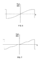
- Phase error signal 36 monotonically increases with the phase difference ( ⁇ ) when the phase difference ( ⁇ ) ranges from -180 degrees to 180 degrees as is illustrated in FIG. 6 .
- Equation 9 is similar to equation 8 but does not include a square root computation, and thus can be computed more quickly.
- the monotonic transfer module 27 comprises an error-tracking loop with the two-phase quantities (V d , Vq) 32, 34 as inputs to generate a monotonic phase error signal 46 which is close to the actual phase difference ( ⁇ ).
- the error-tracking loop comprises a transfer function unit 40 and a regulator 42.
- the error-tracking loop comprises a fast closed loop. Accordingly, the monotonic phase error signal 36 is the estimated phase difference ( ⁇ e ) from the error-tracking loop of the monotonic transfer module 27 which remains in alignment with the actual phase difference ( ⁇ ). In one embodiment, a ratio of a response time t 1 of the PLL circuit and a response time t 2 of the error-tracking loop is at least 10.
- Vq V m ⁇ sin ⁇
- error-tracking unit 48 performs an arctangent function such as in equation 6 above.
- FIG. 10 is similar to that of the embodiment of FIG. 9 and illustrates that the error-tracking unit 48 may comprise an error-tracking loop such as described above with reference to FIG. 8 .
- the monotonic transfer module 27 may comprise any other possible circuit or device capable of receiving two-phase voltage signals (V d , V q ) 32, 34 and generating a phase error signal 36 which monotonically increases with the phase difference ( ⁇ ) ranging from at least -180 degrees to 180 degrees.
- ⁇ phase difference
- One such example is a look-up table.
- the monotonic phase error signal 36 from the monotonic transfer module 27 is sent to phase-error regulator 28.
- the phase error regulator 28 comprises a PI controller for receiving the monotonic phase error signal 36 as an input to generate a regulation signal 39 which is the synchronized frequency ( ⁇ e ) of the grid voltage.
- the PLL circuit 24 provides a faster response than conventional PLL circuits when the phase difference is in the range of - 180 degrees to -90 degrees or 90 degrees to 180 degrees.
- phase error signals of the embodiment of FIG. 5 are monotonic when the phase difference ( ⁇ ) between the reference signal 14 and the synchronized phase signal ( ⁇ ) ranges from -180 degrees to 180 degrees. Accordingly, PLL circuits 24 of various embodiments of the invention provide faster convergences for large phase jumps.
Landscapes
- Stabilization Of Oscillater, Synchronisation, Frequency Synthesizers (AREA)
Abstract
Description
- The invention relates generally to phase-locked loop (PLL) circuits for generating synchronized phase and frequency signals from multi-phase reference signals.
- A phase locked loop (PLL) circuit is a closed loop circuit that generates a synchronized output signal from a reference signal. The PLL circuit automatically responds to the frequency and phase of the reference signal by adjusting the output signal until the output signal is matched to the reference signal in both frequency and phase. In a power control system, for example, the PLL circuit detects the phase information of the grid voltage, so that a power controller can synchronize a converter's output voltage with the grid voltage. During a transient event such as a short circuit fault in power system, the phase angle and magnitude of the reference signal may change significantly, and it is desirable for the PLL circuit to provide a quick response.
- In accordance with an embodiment disclosed herein, a phase-locked loop circuit comprises a phase error detector for receiving a multi-phase reference signal and a synchronized phase signal of the phase-locked-loop circuit, and for performing a rotational transformation to convert the multi-phase reference signal into two-phase quantities at a synchronous rotation d-q reference frame. A monotonic transfer module receives the two-phase quantities, and generates a monotonic phase error signal which is monotonic when a phase difference between the multi-phase reference signal and the synchronized phase signal ranges from -180 degrees to 180 degrees. A regulator receives the monotonic phase error signal, and generates a synchronized rotation frequency. An integrator receives the synchronized rotation frequency, and generates the synchronized phase signal.
- Various features, aspects, and advantages of the present invention will become better understood when the following detailed description is read with reference to the accompanying drawings in which like characters represent like parts throughout the drawings, wherein:
-
FIG. 1 is a block diagram of a conventional phase-locked-loop (PLL) circuit. -
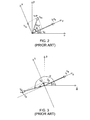
FIG. 2 illustrates a rotational transformation of a phase detector of the PLL circuit ofFIG. 1 , wherein a phase error is less than 90 degrees. -
FIG. 3 illustrates a rotational transformation of the phase detector of the PLL circuit ofFIG. 1 , wherein a phase error is greater than 90 degrees. -
FIG. 4 illustrates a sine-wave characteristic of the phase error detector of the PLL circuit ofFIG. 1 . -
FIG. 5 is a block diagram of an exemplary PLL circuit according to one embodiment of the invention. -
FIGs. 6 and 7 illustrate monotonic characteristics of a monotonic transfer module according different embodiments of the invention. -
FIGs. 8-10 are block diagrams of monotonic transfer modules according to other embodiments of the invention. - Various embodiments of the invention relate to a phase-locked-loop (PLL) circuit for generating synchronized phase and frequency signals from a multi-phase reference signal. The PLL circuit comprises a phase detector for receiving the multi-phase reference signal and a feedback synchronized phase signal and generating two-phase signals in a two-phase direct and quadrature (d-q) reference frame. The PLL circuit comprises a monotonic transfer function for receiving the two-phase signals in the d-q reference frame and for generating a phase error signal. The phase error signal is monotonic for a phase difference between the reference signal and the synchronized phase signal over the range from -180 degrees to 180 degrees.
- To better understand the invention, reference is first made to a
conventional PLL circuit 10 throughFIGs. 1-4 . As illustrated inFIG. 1 , the illustratedPLL circuit 10 comprises aphase detector 12 for receiving amulti-phase reference signal 14 and a synchronizedoutput signal 16 ofPLL circuit 10 and for using these signals to generate aphase error signal 18. Aregulator 20 determines a synchronized frequency (ωe) based on thephase error signal 18. Anintegrator 22 generates a synchronized phase signal (δ), and thus an output signal of the PLL circuit may include synchronized frequency (ωe) and phase (δ) signals. - When
reference signal 14 is a balanced three-phase sinusoidal reference signal with voltage phasors (Va, Vb, and Vc), it can be expressed as equation 1 below:
wherein "Vm" is a voltage amplitude of positive sequence, and "ω" is a fundamental rotational frequency of the three-phase reference signal 14. - Referring to
FIG. 2 , generation ofphase error signal 18 byphase detector 12 typically comprises a rotational transformation.Phase detector 12 may transform the three-phase reference signal (Va, Vb, and Vc) into two-phase quantities (Vα, Vβ) in a two-phase stationary α-β reference frame according toequation 2 below for example:
wherein "Φ" is an instantaneous phase angle of thereference signal 14 and Φ0 is an initial phase angle of thereference phase signal 14. Then, the two-phase quantities (Vα, Vβ) may be transformed into two-phase quantities (Vd, Vq) in a synchronous rotating d-q reference frame according to equation 3:
wherein "δ" is an instantaneous synchronized phase angle, and "ωe" is a synchronized rotation speed, and thus:
Vd = Vα × cos δ + Vβ × sin δ = Vm × cos Φ cos δ + Vm × sin Φ sin δ = Vm × cos(Φ - δ) = Vm ×cosθ equation 4
Vq = Vα × (-sin δ) + Vβ × cos δ = Vm × cos Φ(-sin δ) + Vm × sin Φ cos δ = Vm × sin(Φ - δ) = Vm × sin θ equation 5
wherein "θ" is a phase error of the phase (Φ) of reference voltage signal (Va, Vb, Vc) 14 and the synchronized phase (δ), i.e. θ= Φ - δ. Thephase error signal 18 fromphase detector 12 is typically the value of Vq. If Vq=0, that is a phase lock status, and no adjustment is needed. If Vq ≠ 0, there is a margin of adjustment, andPLL circuit 10 will provide adjusted synchronized output signal for adjustment of phase, frequency, or both phase and frequency. - As is shown in
FIG. 2 , Vq = V×sinθ, and thephase error signal 18 of thephase detector 12 has a sine-wave characteristic. Referring toFIGs. 2 and4 , while the phase difference (θ1) remains within a range of -90 degrees to 90 degrees, thephase error signal 18 is monotonic with respect to the phase displacement (θ1), andPLL circuit 10 is capable of performing smooth acquisition and adjustment. Referring toFIGs. 3 and4 , however, when the phase difference (θ2) is within -180 degrees to -90 degrees or within 90 degrees to 180 degrees, thephase error signal 18 decreases while phase difference (θ2) increases. Under a transient condition such as a grid voltage event with phase jump, with or without changes in frequency, the phase difference (θ) may jump to the range of 180 degrees to -90 degrees or 90 degrees to 180 degrees, and, particularly when the correspondingphase error signal 18 is small, the convergence of thePLL circuit 10 is undesirably slowed down. - Referring to
FIG. 5 , aPLL circuit 24 according to one embodiment of the invention comprises aphase detector 26, amonotonic transfer module 27, a phase-error regulator 28, and anintegrator 30.Phase detector 26 receives amulti-phase reference signal 14 which, in one embodiment, is a three-phase voltage signal (Va, Vb, Vc) for example.Phase detector 26 further receives a synchronizedoutput signal 38 ofPLL circuit 24 and uses both signals to generate two-phase signals (Vd, Vq) 32, 34 in a synchronous two-phase d-q reference frame. In certain embodiments of the invention, generation of the two-phase voltage signals (Vd, Vq) 32, 34 in the d-q reference frame is accomplished in a similar manner as described with respect to the transformation performed by thephase detector 12 ofFIG. 1 . A phase difference (θ) between the three phase reference signal (Va, Vb, Vc) and thesynchronized output signal 38 ofPLL circuit 24 can be obtained according to equation 6 below:
- In certain embodiments of the invention,
monotonic transfer module 27 is configured to receive the two-phase signal (Vd, Vq) 32, 34 and to generate a monotonicphase error signal 36 which monotonically increases with respect to the phase difference (θ) when ranging from -180 degrees to 180 degrees. In certain embodiments of the invention, themonotonic transfer module 27 comprises a monotonic transfer function (f(Vd, Vq)) to generate the monotonicphase error signal 36 with the two-phase quantities Vd and Vq as inputs. In one embodiment, the monotonic transfer function (f(Vd, Vq)) comprises an arctangent function according to equation 7 below:
wherein k1 is a coefficient. In one embodiment, k1 comprises 2, for example. Thus, thephase error signal 36 linearly increases when the phase difference (θ) ranges from -180 degrees to 180 degrees. - In accordance with another embodiment, the monotonic transfer function (f(Vd, Vq)) of the
monotonic transfer module 27 is performed as a sine function of one half of the phase difference according toequation 8 below:
wherein k2 is a coefficient. In one embodiment k2 comprises 2, for example.Phase error signal 36 monotonically increases with the phase difference (θ) when the phase difference (θ) ranges from -180 degrees to 180 degrees as is illustrated inFIG. 6 . - In accordance with still another embodiment, the monotonic transfer function (f(Vd, Vq)) is a signum function according to
equation 9 below:
- The monotonic
phase error signal 36 generated according toequation 8 is illustrated inFIG. 7 .Equation 9 is similar toequation 8 but does not include a square root computation, and thus can be computed more quickly. - In still anther embodiment, with reference to
FIG. 8 , themonotonic transfer module 27 comprises an error-tracking loop with the two-phase quantities (Vd, Vq) 32, 34 as inputs to generate a monotonicphase error signal 46 which is close to the actual phase difference (θ). In the illustrated embodiment, the error-tracking loop comprises atransfer function unit 40 and aregulator 42. Thetransfer function unit 40 is configured to receive the two-phase quantities (Vd, Vq) 32, 34 and an estimated phase difference (θe) 44, and generate anerror signal 46 which is an indication of the difference of the actual phase difference (θ) and the estimated phase difference (θe) 44 according toequation 10 below for example:
wherein k4 is a coefficient, and in one embodiment, k4 >1. Theerror signal 46 is transmitted to theregulator 42 to generate the estimated phase difference (θe) 44. If error signal =0, θ = θe, the estimated phase difference (θe) 44 is the same as the actual phase difference (θ). If error signal ≠ 0, the estimated phase difference (θe) 44 is not the same as the actual phase difference (θ), and theregulator 42 generates a new phase difference signal (θe) until the error signal =0. This new phase difference signal is monotonic beyond the range of -180 degrees to 180 degrees. In certain embodiments, the error-tracking loop comprises a fast closed loop. Accordingly, the monotonicphase error signal 36 is the estimated phase difference (θe) from the error-tracking loop of themonotonic transfer module 27 which remains in alignment with the actual phase difference (θ). In one embodiment, a ratio of a response time t1 of the PLL circuit and a response time t2 of the error-tracking loop is at least 10. - In the embodiments of
FIGs. 9 and 10 , themonotonic transfer module 27 comprises an error-trackingunit 48 configured to receive the two-phase quantities (Vd, Vq) 32, 34 and to generate anerror signal 50 which is substantially equal to the phase difference (θ), again adjustment element 52 for receiving the quantity (Vq) 34 and for generating anerror signal 54 which is substantially equal to the value of sin (θ), and a summingjunction 56 for receiving the error signals 50, 54 and generating monotonicphase error signal 36 according to equation 11 below:
- In one embodiment, according to equation 5, Vq= Vm × sin θ, and
error signal 50 is obtained by adjusting the quantity (Vq) bygain adjustment element 52 according to:
wherein
- In the embodiment of
FIG. 9 , error-trackingunit 48 performs an arctangent function such as in equation 6 above. In one specific embodiment, error-trackingunit 48 performs an arctangent function such asequation 12 below:
wherein "N" is a coefficient. In one embodiment, N>1. A larger value for the coefficient (N) will increase the response to phase jumps. In one embodiment, "N" comprises 100. - The embodiment of
FIG. 10 is similar to that of the embodiment ofFIG. 9 and illustrates that the error-trackingunit 48 may comprise an error-tracking loop such as described above with reference toFIG. 8 . - In other embodiments of the invention, the
monotonic transfer module 27 may comprise any other possible circuit or device capable of receiving two-phase voltage signals (Vd, Vq) 32, 34 and generating aphase error signal 36 which monotonically increases with the phase difference (θ) ranging from at least -180 degrees to 180 degrees. One such example is a look-up table. - Referring back to
FIG. 5 , the monotonicphase error signal 36 from themonotonic transfer module 27 is sent to phase-error regulator 28. In one embodiment of the invention, thephase error regulator 28 comprises a PI controller for receiving the monotonicphase error signal 36 as an input to generate aregulation signal 39 which is the synchronized frequency (ωe) of the grid voltage. - In the illustrated embodiment of
FIG. 5 ,integrator 30 is configured to receive the synchronized rotation frequency (ωe) 39 from phase-error regulator 28 and to generate the synchronized phase angle signal (δ) by a time integration as equation 13, for example:
- As the phase error signal is in a monotonic relationship when the phase difference (θ) ranges from -180 degrees to 180 degrees, the
PLL circuit 24 provides a faster response than conventional PLL circuits when the phase difference is in the range of - 180 degrees to -90 degrees or 90 degrees to 180 degrees. - As compared with the
conventional PLL circuit 10 as described with reference toFIGs. 1-4 , phase error signals of the embodiment ofFIG. 5 are monotonic when the phase difference (θ) between thereference signal 14 and the synchronized phase signal (δ) ranges from -180 degrees to 180 degrees. Accordingly,PLL circuits 24 of various embodiments of the invention provide faster convergences for large phase jumps. - Unless defined otherwise, technical and scientific terms used herein have the same meaning as is commonly understood by one of skill in the art to which this invention belongs. The terms "first", "second", and the like, as used herein do not denote any order, quantity, or importance, but rather are used to distinguish one element from another. Also, the terms "a" and "an" do not denote a limitation of quantity, but rather denote the presence of at least one of the referenced items, and terms such as "front", "back", "bottom", and/or "top", unless otherwise noted, are merely used for convenience of description, and are not limited to any one position or spatial orientation.
- While the invention has been described with reference to exemplary embodiments, it will be understood by those skilled in the art that various changes may be made and equivalents may be substituted for elements thereof without departing from the scope of the invention. In addition, many modifications may be made to adapt a particular situation or material to the teachings of the invention without departing from the essential scope thereof. Therefore, it is intended that the invention not be limited to the particular embodiment disclosed as the preferred mode contemplated for carrying out this invention, but that the invention will include all embodiments falling within the scope of the appended claims.
- It is to be understood that not necessarily all such objects or advantages described above may be achieved in accordance with any particular embodiment. Thus, for example, those skilled in the art will recognize that the systems and techniques described herein may be embodied or carried out in a manner that achieves or optimizes one advantage or group of advantages as taught herein without necessarily achieving other objects or advantages as may be taught or suggested herein.
- Furthermore, the skilled artisan will recognize the interchangeability of various features from different embodiments. The various features described, as well as other known equivalents for each feature, can be mixed and matched by one of ordinary skill in this art to construct additional systems and techniques in accordance with principles of this disclosure.
- Various aspects and embodiments of the present invention are defined by the following numbered clauses:
- 1. A phase-locked loop circuit comprising:
- a phase error detector for receiving a multi-phase reference signal and a synchronized phase signal of the phase-locked-loop circuit, and for performing a rotational transformation to convert the multi-phase reference signal into two-phase quantities at a synchronous rotation d-q reference frame;
- a monotonic transfer module for receiving the two-phase quantities, and for generating a monotonic phase error signal which is monotonic when a phase difference between the multi-phase reference signal and the synchronized phase signal ranges from -180 degrees to 180 degrees; and
- a regulator for receiving the monotonic phase error signal, and for generating a synchronized rotation frequency; and
- an integrator for receiving the synchronized rotation frequency, and for generating the synchronized phase signal.
- 2. The phase-locked loop circuit of clause 1, wherein the monotonic transfer module is configured to perform an arctangent function of the two-phase quantities.
- 3. The phase-locked loop circuit of any preceding clause, wherein the monotonic transfer module is configured to perform a sine function of one half of the phase difference according to the two-phase quantities.
- 4. The phase-locked loop circuit of any preceding clause, wherein the monotonic transfer module is configured to perform a variation of a sine function of one half of the phase difference according to the following equation:

- 5. The phase-locked loop circuit of any preceding clause, wherein the monotonic transfer module is configured to generate the monotonic phase error signal by searching in a look-up table.
- 6. The phase-locked loop circuit of any preceding clause, wherein the monotonic transfer module comprises an error-tracking loop for receiving the two-phase quantities and for generating an estimated phase difference.
- 7. The phase-locked loop circuit of any preceding clause, wherein the error-tracking loop comprises a transfer function unit for receiving the two-phase quantities and the estimated phase difference and for generating an error signal from a difference of the estimated phase difference and an actual phase difference, and a regulator for generating the estimated phase difference.
- 8. The phase-locked loop circuit of any preceding clause, wherein a ratio of a response time of the phase-locked loop circuit to a response time of the error-tracking loop is at least 10.
- 9. The phase-locked loop circuit of any preceding clause, wherein the transfer function unit is configured to perform a sine function of the difference of the estimated phase difference and the actual phase difference to generate the error signal.
- 10. The phase-locked loop circuit of any preceding clause, wherein the monotonic transfer module comprises an error-tracking unit for receiving the two-phase quantities and for generating an error signal which is substantially equal to the phase difference, a gain adjustment element for adjusting the two-phase quantity in a q axis of the synchronous rotation d-q reference frame to get an error signal, and a summing junction for receiving the error signal from the error-tracking unit and gain adjustment element to generate the monotonic phase error signal.
- 11. The phase-locked loop circuit of any preceding clause, wherein the error-tracking unit is configured to perform an arctangent function of the two-phase quantities to generate the error signal.
- 12. The phase-locked loop circuit of any preceding clause, wherein the error-tracking unit is configured to perform the arctangent function in accordance with:

wherein "N" is constant coefficient, and N>1. - 13. The phase-locked loop circuit of any preceding clause, wherein the error-tracking unit comprises an error-tracking loop for receiving the two-phase quantities and for generating an estimated phase difference substantially equal to an actual phase difference.
Claims (10)
- A phase-locked loop circuit (24) comprising:a phase error detector (26) for receiving a multi-phase reference signal (40) and a synchronized phase signal (38) of the phase-locked-loop circuit, and for performing a rotational transformation to convert the multi-phase reference signal into two-phase quantities (32, 34) at a synchronous rotation d-q reference frame;a monotonic transfer module (27) for receiving the two-phase quantities, and for generating a monotonic phase error signal (36) which is monotonic when a phase difference between the multi-phase reference signal and the synchronized phase signal ranges from -180 degrees to 180 degrees; anda regulator (28) for receiving the monotonic phase error signal, and for generating a synchronized rotation frequency (39); andan integrator (30) for receiving the synchronized rotation frequency, and for generating the synchronized phase signal.
- The phase-locked loop circuit (24) of claim 1, wherein the monotonic transfer module is configured to perform an arctangent function of the two-phase quantities.
- The phase-locked loop circuit (24) of any preceding claim, wherein the monotonic transfer module is configured to perform a sine function of one half of the phase difference according to the two-phase quantities.
- The phase-locked loop circuit (24) of any preceding claim, wherein the monotonic transfer module is configured to perform a variation of a sine function of one half of the phase difference according to the following equation:

wherein k is a coefficient, and Vd and Vq are respectively the two-phase quantities of the synchronous rotation d-q reference frame. - The phase-locked loop circuit (24) of any preceding claim, wherein the monotonic transfer module is configured to generate the monotonic phase error signal by searching in a look-up table.
- The phase-locked loop circuit (24) of any preceding claim, wherein the monotonic transfer module comprises an error-tracking loop for receiving the two-phase quantities and for generating an estimated phase difference.
- The phase-locked loop circuit (24) of claim 6, wherein the error-tracking loop comprises a transfer function unit for receiving the two-phase quantities and the estimated phase difference and for generating an error signal from a difference of the estimated phase difference and an actual phase difference, and a regulator for generating the estimated phase difference.
- The phase-locked loop circuit of (24) of any preceding claim, wherein a ratio of a response time of the phase-locked loop circuit to a response time of the error-tracking loop is at least 10.
- The phase-locked loop circuit of (24) of any preceding claim, wherein the transfer function unit is configured to perform a sine function of the difference of the estimated phase difference and the actual phase difference to generate the error signal.
- The phase-locked loop circuit of (24) of any preceding claim, wherein the monotonic transfer module comprises an error-tracking unit for receiving the two-phase quantities and for generating an error signal which is substantially equal to the phase difference, a gain adjustment element for adjusting the two-phase quantity in a q axis of the synchronous rotation d-q reference frame to get an error signal, and a summing junction for receiving the error signal from the error-tracking unit and gain adjustment element to generate the monotonic phase error signal.
Applications Claiming Priority (1)
| Application Number | Priority Date | Filing Date | Title |
|---|---|---|---|
| US12/569,119 US7928780B1 (en) | 2009-09-29 | 2009-09-29 | Phase-locked-loop circuit |
Publications (3)
| Publication Number | Publication Date |
|---|---|
| EP2306649A2 true EP2306649A2 (en) | 2011-04-06 |
| EP2306649A3 EP2306649A3 (en) | 2011-06-08 |
| EP2306649B1 EP2306649B1 (en) | 2012-08-22 |
Family
ID=43431116
Family Applications (1)
| Application Number | Title | Priority Date | Filing Date |
|---|---|---|---|
| EP10178724A Not-in-force EP2306649B1 (en) | 2009-09-29 | 2010-09-23 | Phase-locked-loop circuit |
Country Status (5)
| Country | Link |
|---|---|
| US (1) | US7928780B1 (en) |
| EP (1) | EP2306649B1 (en) |
| CN (1) | CN102035541B (en) |
| DK (1) | DK2306649T3 (en) |
| ES (1) | ES2393661T3 (en) |
Cited By (1)
| Publication number | Priority date | Publication date | Assignee | Title |
|---|---|---|---|---|
| DE102012102744A1 (en) | 2012-03-29 | 2013-10-02 | Sma Solar Technology Ag | Method for providing phase locked reference signal for inverter, involves determining frequency and phase of reference signal based on stored variables and operating state, when error is detected |
Families Citing this family (12)
| Publication number | Priority date | Publication date | Assignee | Title |
|---|---|---|---|---|
| EP2771955B1 (en) * | 2011-10-28 | 2017-12-13 | General Electric Company | Systems and methods for using in identifying and responding to type of grid fault event |
| IN2014CN03545A (en) | 2011-10-28 | 2015-07-03 | Gen Electric | |
| CN102957451B (en) * | 2012-11-14 | 2014-08-13 | 东南大学 | Frequency-phase combined jumping communication method |
| CN103280842B (en) * | 2013-04-22 | 2014-12-17 | 华中科技大学 | Synchronization control method and synchronization control system for generating converter internal frequency by direct current (DC) voltage |
| CN103487652B (en) * | 2013-09-03 | 2015-07-15 | 电子科技大学 | Frequency self-adaptive real-time fractional harmonic wave detection method |
| US9548690B2 (en) | 2014-02-28 | 2017-01-17 | General Electric Company | System and method for adjusting current regulator gains applied within a power generation system |
| US9520819B2 (en) | 2014-02-28 | 2016-12-13 | General Electric Company | System and method for controlling a power generation system based on a detected islanding event |
| US9641113B2 (en) | 2014-02-28 | 2017-05-02 | General Electric Company | System and method for controlling a power generation system based on PLL errors |
| EP2955812B1 (en) * | 2014-06-09 | 2022-07-27 | General Electric Technology GmbH | Power transmission network |
| CN104836255A (en) * | 2015-05-27 | 2015-08-12 | 重庆大学 | Implicit PI-based digital phase-locked loop and power grid synchronization system |
| TWI634748B (en) * | 2017-12-05 | 2018-09-01 | 財團法人工業技術研究院 | Measuring apparatus including phase locked loop and measuring method thereof |
| JP7024697B2 (en) * | 2018-12-11 | 2022-02-24 | 株式会社明電舎 | Phase-locked loop |
Family Cites Families (9)
| Publication number | Priority date | Publication date | Assignee | Title |
|---|---|---|---|---|
| JPH0824260B2 (en) * | 1987-05-26 | 1996-03-06 | 日本電気株式会社 | Phase comparator |
| US6853940B2 (en) | 2002-01-16 | 2005-02-08 | Ballard Power Systems Corporation | Anti-islanding device and method for grid connected inverters using random noise injection |
| US7106564B2 (en) * | 2002-01-16 | 2006-09-12 | Ballard Power Systems Corporation | Devices and methods for detecting islanding operation of a static power source |
| GB0323936D0 (en) * | 2003-10-11 | 2003-11-12 | Zarlink Semiconductor Inc | Digital phase locked loop with selectable normal or fast-locking capability |
| US20070005194A1 (en) | 2005-06-20 | 2007-01-04 | Liuchen Chang | System for three-phase voltage detection and protection |
| US7492617B2 (en) | 2005-06-29 | 2009-02-17 | Northern Power Systems, Inc. | Frequency control and power balancing in disturbed power inverter system and method thereof |
| CN101617234B (en) * | 2006-11-06 | 2012-05-23 | 歌美飒创新技术公司 | Advanced real-time grid monitoring system |
| US7642737B2 (en) * | 2007-03-13 | 2010-01-05 | Gm Global Technology Operations, Inc. | Anti-windup control for a current regulator of a pulse width modulation inverter |
| US8212505B2 (en) * | 2008-12-02 | 2012-07-03 | GM Global Technology Operations LLC | Method and system for creating a vibration in an automobile |
-
2009
- 2009-09-29 US US12/569,119 patent/US7928780B1/en not_active Expired - Fee Related
-
2010
- 2010-09-23 ES ES10178724T patent/ES2393661T3/en active Active
- 2010-09-23 EP EP10178724A patent/EP2306649B1/en not_active Not-in-force
- 2010-09-23 DK DK10178724.0T patent/DK2306649T3/en active
- 2010-09-29 CN CN201010513043.1A patent/CN102035541B/en not_active Expired - Fee Related
Non-Patent Citations (1)
| Title |
|---|
| None |
Cited By (2)
| Publication number | Priority date | Publication date | Assignee | Title |
|---|---|---|---|---|
| DE102012102744A1 (en) | 2012-03-29 | 2013-10-02 | Sma Solar Technology Ag | Method for providing phase locked reference signal for inverter, involves determining frequency and phase of reference signal based on stored variables and operating state, when error is detected |
| DE102012102744B4 (en) * | 2012-03-29 | 2016-11-10 | Sma Solar Technology Ag | Inverter and method and apparatus for phase synchronization of an inverter |
Also Published As
| Publication number | Publication date |
|---|---|
| EP2306649A3 (en) | 2011-06-08 |
| CN102035541A (en) | 2011-04-27 |
| ES2393661T3 (en) | 2012-12-27 |
| CN102035541B (en) | 2015-02-11 |
| US20110074474A1 (en) | 2011-03-31 |
| US7928780B1 (en) | 2011-04-19 |
| EP2306649B1 (en) | 2012-08-22 |
| DK2306649T3 (en) | 2012-11-05 |
Similar Documents
| Publication | Publication Date | Title |
|---|---|---|
| EP2306649A2 (en) | Phase-locked-loop circuit | |
| EP2302783B1 (en) | Power conversion control system | |
| US9509145B2 (en) | Distributed power supply system | |
| US8743571B2 (en) | Distributed power supply system with harmonic signal generation for stabilization | |
| US10978866B2 (en) | Polarizing signal for electric power delivery system protection | |
| CN103683319A (en) | Grid connected inverter control method based on hysteresis modulation under unbalanced grid voltage condition | |
| CN106849941B (en) | Method and device for realizing software phase-locked loop | |
| US6919650B2 (en) | Hybrid synchronization phase angle generation method | |
| CN103901306A (en) | Method for detecting power grid voltage leap failures | |
| Kamil et al. | Recent advances in phase-locked loop based synchronization methods for inverter-based renewable energy sources | |
| CN101964655B (en) | Balance error elimination type high-precision digital phase locking method | |
| CN104410407B (en) | A kind of adaptive digital phaselocked loop and phase-lock technique | |
| CN102761281A (en) | Phase-locked control system for inverter and phase locking method thereof | |
| CN107623333A (en) | The distributed photovoltaic output current analysis method of the dynamic reclosing process of phaselocked loop | |
| Kalaivani et al. | Grid Integration of Three-phase Inverter using Decoupled Double Synchronus Reference Frame PLL | |
| Rahoui et al. | Simplified sensorless predictive control of grid-side converter in wind energy conversion systems under distorted grid conditions | |
| Sen et al. | DSRF and SOGI based PLL-two viable scheme for grid synchronization of DG systems during grid abnormalities | |
| Mnider et al. | A programmable cascaded LPF based PLL scheme for single-phase grid-connected inverters | |
| CN103312129B (en) | A kind of single-phase converter reactive power control method and device | |
| CN109638877B (en) | Phase-locked loop control method for synchronization of grid-connected converter and power grid signals | |
| Sevilmis et al. | Performance analysis of dual second order generalized integrator phase locked loop for grid interactive inverter | |
| Teja et al. | A Novel Variable Time Delay FLL Based Estimation of Positive and Negative Sequence Components of Grid | |
| Gautam et al. | Fast identification of active and reactive current component for single phase grid interconnection | |
| Matakas et al. | Positive sequence tracking Phase Locked Loops: A unified graphical explanation | |
| Hsieh | Phase-Lock-Loop-Based Control |
Legal Events
| Date | Code | Title | Description |
|---|---|---|---|
| PUAI | Public reference made under article 153(3) epc to a published international application that has entered the european phase |
Free format text: ORIGINAL CODE: 0009012 |
|
| AK | Designated contracting states |
Kind code of ref document: A2 Designated state(s): AL AT BE BG CH CY CZ DE DK EE ES FI FR GB GR HR HU IE IS IT LI LT LU LV MC MK MT NL NO PL PT RO SE SI SK SM TR |
|
| AX | Request for extension of the european patent |
Extension state: BA ME RS |
|
| PUAL | Search report despatched |
Free format text: ORIGINAL CODE: 0009013 |
|
| AK | Designated contracting states |
Kind code of ref document: A3 Designated state(s): AL AT BE BG CH CY CZ DE DK EE ES FI FR GB GR HR HU IE IS IT LI LT LU LV MC MK MT NL NO PL PT RO SE SI SK SM TR |
|
| AX | Request for extension of the european patent |
Extension state: BA ME RS |
|
| RIC1 | Information provided on ipc code assigned before grant |
Ipc: H03L 7/085 20060101AFI20110301BHEP Ipc: H02J 3/40 20060101ALI20110429BHEP |
|
| 17P | Request for examination filed |
Effective date: 20111208 |
|
| GRAP | Despatch of communication of intention to grant a patent |
Free format text: ORIGINAL CODE: EPIDOSNIGR1 |
|
| GRAS | Grant fee paid |
Free format text: ORIGINAL CODE: EPIDOSNIGR3 |
|
| GRAA | (expected) grant |
Free format text: ORIGINAL CODE: 0009210 |
|
| AK | Designated contracting states |
Kind code of ref document: B1 Designated state(s): AL AT BE BG CH CY CZ DE DK EE ES FI FR GB GR HR HU IE IS IT LI LT LU LV MC MK MT NL NO PL PT RO SE SI SK SM TR |
|
| REG | Reference to a national code |
Ref country code: GB Ref legal event code: FG4D |
|
| REG | Reference to a national code |
Ref country code: CH Ref legal event code: EP |
|
| REG | Reference to a national code |
Ref country code: IE Ref legal event code: FG4D |
|
| REG | Reference to a national code |
Ref country code: AT Ref legal event code: REF Ref document number: 572413 Country of ref document: AT Kind code of ref document: T Effective date: 20120915 |
|
| REG | Reference to a national code |
Ref country code: DE Ref legal event code: R096 Ref document number: 602010002443 Country of ref document: DE Effective date: 20121018 |
|
| REG | Reference to a national code |
Ref country code: DK Ref legal event code: T3 |
|
| REG | Reference to a national code |
Ref country code: NL Ref legal event code: VDEP Effective date: 20120822 Ref country code: ES Ref legal event code: FG2A Ref document number: 2393661 Country of ref document: ES Kind code of ref document: T3 Effective date: 20121227 |
|
| REG | Reference to a national code |
Ref country code: AT Ref legal event code: MK05 Ref document number: 572413 Country of ref document: AT Kind code of ref document: T Effective date: 20120822 |
|
| REG | Reference to a national code |
Ref country code: LT Ref legal event code: MG4D Effective date: 20120822 |
|
| PG25 | Lapsed in a contracting state [announced via postgrant information from national office to epo] |
Ref country code: AT Free format text: LAPSE BECAUSE OF FAILURE TO SUBMIT A TRANSLATION OF THE DESCRIPTION OR TO PAY THE FEE WITHIN THE PRESCRIBED TIME-LIMIT Effective date: 20120822 Ref country code: HR Free format text: LAPSE BECAUSE OF FAILURE TO SUBMIT A TRANSLATION OF THE DESCRIPTION OR TO PAY THE FEE WITHIN THE PRESCRIBED TIME-LIMIT Effective date: 20120822 Ref country code: FI Free format text: LAPSE BECAUSE OF FAILURE TO SUBMIT A TRANSLATION OF THE DESCRIPTION OR TO PAY THE FEE WITHIN THE PRESCRIBED TIME-LIMIT Effective date: 20120822 Ref country code: NO Free format text: LAPSE BECAUSE OF FAILURE TO SUBMIT A TRANSLATION OF THE DESCRIPTION OR TO PAY THE FEE WITHIN THE PRESCRIBED TIME-LIMIT Effective date: 20121122 Ref country code: IS Free format text: LAPSE BECAUSE OF FAILURE TO SUBMIT A TRANSLATION OF THE DESCRIPTION OR TO PAY THE FEE WITHIN THE PRESCRIBED TIME-LIMIT Effective date: 20121222 Ref country code: LT Free format text: LAPSE BECAUSE OF FAILURE TO SUBMIT A TRANSLATION OF THE DESCRIPTION OR TO PAY THE FEE WITHIN THE PRESCRIBED TIME-LIMIT Effective date: 20120822 |
|
| PG25 | Lapsed in a contracting state [announced via postgrant information from national office to epo] |
Ref country code: PT Free format text: LAPSE BECAUSE OF FAILURE TO SUBMIT A TRANSLATION OF THE DESCRIPTION OR TO PAY THE FEE WITHIN THE PRESCRIBED TIME-LIMIT Effective date: 20121224 Ref country code: GR Free format text: LAPSE BECAUSE OF FAILURE TO SUBMIT A TRANSLATION OF THE DESCRIPTION OR TO PAY THE FEE WITHIN THE PRESCRIBED TIME-LIMIT Effective date: 20121123 Ref country code: SE Free format text: LAPSE BECAUSE OF FAILURE TO SUBMIT A TRANSLATION OF THE DESCRIPTION OR TO PAY THE FEE WITHIN THE PRESCRIBED TIME-LIMIT Effective date: 20120822 Ref country code: BE Free format text: LAPSE BECAUSE OF FAILURE TO SUBMIT A TRANSLATION OF THE DESCRIPTION OR TO PAY THE FEE WITHIN THE PRESCRIBED TIME-LIMIT Effective date: 20120822 Ref country code: LV Free format text: LAPSE BECAUSE OF FAILURE TO SUBMIT A TRANSLATION OF THE DESCRIPTION OR TO PAY THE FEE WITHIN THE PRESCRIBED TIME-LIMIT Effective date: 20120822 Ref country code: SI Free format text: LAPSE BECAUSE OF FAILURE TO SUBMIT A TRANSLATION OF THE DESCRIPTION OR TO PAY THE FEE WITHIN THE PRESCRIBED TIME-LIMIT Effective date: 20120822 |
|
| PG25 | Lapsed in a contracting state [announced via postgrant information from national office to epo] |
Ref country code: NL Free format text: LAPSE BECAUSE OF FAILURE TO SUBMIT A TRANSLATION OF THE DESCRIPTION OR TO PAY THE FEE WITHIN THE PRESCRIBED TIME-LIMIT Effective date: 20120822 |
|
| PG25 | Lapsed in a contracting state [announced via postgrant information from national office to epo] |
Ref country code: EE Free format text: LAPSE BECAUSE OF FAILURE TO SUBMIT A TRANSLATION OF THE DESCRIPTION OR TO PAY THE FEE WITHIN THE PRESCRIBED TIME-LIMIT Effective date: 20120822 Ref country code: MC Free format text: LAPSE BECAUSE OF NON-PAYMENT OF DUE FEES Effective date: 20120930 Ref country code: RO Free format text: LAPSE BECAUSE OF FAILURE TO SUBMIT A TRANSLATION OF THE DESCRIPTION OR TO PAY THE FEE WITHIN THE PRESCRIBED TIME-LIMIT Effective date: 20120822 Ref country code: CZ Free format text: LAPSE BECAUSE OF FAILURE TO SUBMIT A TRANSLATION OF THE DESCRIPTION OR TO PAY THE FEE WITHIN THE PRESCRIBED TIME-LIMIT Effective date: 20120822 |
|
| PG25 | Lapsed in a contracting state [announced via postgrant information from national office to epo] |
Ref country code: SK Free format text: LAPSE BECAUSE OF FAILURE TO SUBMIT A TRANSLATION OF THE DESCRIPTION OR TO PAY THE FEE WITHIN THE PRESCRIBED TIME-LIMIT Effective date: 20120822 Ref country code: IT Free format text: LAPSE BECAUSE OF FAILURE TO SUBMIT A TRANSLATION OF THE DESCRIPTION OR TO PAY THE FEE WITHIN THE PRESCRIBED TIME-LIMIT Effective date: 20120822 Ref country code: PL Free format text: LAPSE BECAUSE OF FAILURE TO SUBMIT A TRANSLATION OF THE DESCRIPTION OR TO PAY THE FEE WITHIN THE PRESCRIBED TIME-LIMIT Effective date: 20120822 |
|
| REG | Reference to a national code |
Ref country code: IE Ref legal event code: MM4A |
|
| PLBE | No opposition filed within time limit |
Free format text: ORIGINAL CODE: 0009261 |
|
| REG | Reference to a national code |
Ref country code: FR Ref legal event code: ST Effective date: 20130531 |
|
| STAA | Information on the status of an ep patent application or granted ep patent |
Free format text: STATUS: NO OPPOSITION FILED WITHIN TIME LIMIT |
|
| 26N | No opposition filed |
Effective date: 20130523 |
|
| PG25 | Lapsed in a contracting state [announced via postgrant information from national office to epo] |
Ref country code: BG Free format text: LAPSE BECAUSE OF FAILURE TO SUBMIT A TRANSLATION OF THE DESCRIPTION OR TO PAY THE FEE WITHIN THE PRESCRIBED TIME-LIMIT Effective date: 20121122 Ref country code: IE Free format text: LAPSE BECAUSE OF NON-PAYMENT OF DUE FEES Effective date: 20120923 |
|
| PG25 | Lapsed in a contracting state [announced via postgrant information from national office to epo] |
Ref country code: FR Free format text: LAPSE BECAUSE OF NON-PAYMENT OF DUE FEES Effective date: 20121022 |
|
| REG | Reference to a national code |
Ref country code: DE Ref legal event code: R097 Ref document number: 602010002443 Country of ref document: DE Effective date: 20130523 |
|
| PG25 | Lapsed in a contracting state [announced via postgrant information from national office to epo] |
Ref country code: MT Free format text: LAPSE BECAUSE OF FAILURE TO SUBMIT A TRANSLATION OF THE DESCRIPTION OR TO PAY THE FEE WITHIN THE PRESCRIBED TIME-LIMIT Effective date: 20120822 Ref country code: CY Free format text: LAPSE BECAUSE OF FAILURE TO SUBMIT A TRANSLATION OF THE DESCRIPTION OR TO PAY THE FEE WITHIN THE PRESCRIBED TIME-LIMIT Effective date: 20120822 Ref country code: AL Free format text: LAPSE BECAUSE OF FAILURE TO SUBMIT A TRANSLATION OF THE DESCRIPTION OR TO PAY THE FEE WITHIN THE PRESCRIBED TIME-LIMIT Effective date: 20120822 |
|
| PG25 | Lapsed in a contracting state [announced via postgrant information from national office to epo] |
Ref country code: TR Free format text: LAPSE BECAUSE OF FAILURE TO SUBMIT A TRANSLATION OF THE DESCRIPTION OR TO PAY THE FEE WITHIN THE PRESCRIBED TIME-LIMIT Effective date: 20120822 |
|
| PG25 | Lapsed in a contracting state [announced via postgrant information from national office to epo] |
Ref country code: SM Free format text: LAPSE BECAUSE OF FAILURE TO SUBMIT A TRANSLATION OF THE DESCRIPTION OR TO PAY THE FEE WITHIN THE PRESCRIBED TIME-LIMIT Effective date: 20120822 Ref country code: LU Free format text: LAPSE BECAUSE OF NON-PAYMENT OF DUE FEES Effective date: 20120923 |
|
| PG25 | Lapsed in a contracting state [announced via postgrant information from national office to epo] |
Ref country code: HU Free format text: LAPSE BECAUSE OF FAILURE TO SUBMIT A TRANSLATION OF THE DESCRIPTION OR TO PAY THE FEE WITHIN THE PRESCRIBED TIME-LIMIT Effective date: 20100923 |
|
| REG | Reference to a national code |
Ref country code: CH Ref legal event code: PL |
|
| GBPC | Gb: european patent ceased through non-payment of renewal fee |
Effective date: 20140923 |
|
| PG25 | Lapsed in a contracting state [announced via postgrant information from national office to epo] |
Ref country code: GB Free format text: LAPSE BECAUSE OF NON-PAYMENT OF DUE FEES Effective date: 20140923 Ref country code: MK Free format text: LAPSE BECAUSE OF FAILURE TO SUBMIT A TRANSLATION OF THE DESCRIPTION OR TO PAY THE FEE WITHIN THE PRESCRIBED TIME-LIMIT Effective date: 20120822 Ref country code: CH Free format text: LAPSE BECAUSE OF NON-PAYMENT OF DUE FEES Effective date: 20140930 Ref country code: LI Free format text: LAPSE BECAUSE OF NON-PAYMENT OF DUE FEES Effective date: 20140930 |
|
| PGFP | Annual fee paid to national office [announced via postgrant information from national office to epo] |
Ref country code: DE Payment date: 20180821 Year of fee payment: 9 |
|
| PGFP | Annual fee paid to national office [announced via postgrant information from national office to epo] |
Ref country code: DK Payment date: 20180824 Year of fee payment: 9 |
|
| PGFP | Annual fee paid to national office [announced via postgrant information from national office to epo] |
Ref country code: ES Payment date: 20181001 Year of fee payment: 9 |
|
| REG | Reference to a national code |
Ref country code: DE Ref legal event code: R119 Ref document number: 602010002443 Country of ref document: DE |
|
| REG | Reference to a national code |
Ref country code: DK Ref legal event code: EBP Effective date: 20190930 |
|
| PG25 | Lapsed in a contracting state [announced via postgrant information from national office to epo] |
Ref country code: DE Free format text: LAPSE BECAUSE OF NON-PAYMENT OF DUE FEES Effective date: 20200401 |
|
| PG25 | Lapsed in a contracting state [announced via postgrant information from national office to epo] |
Ref country code: DK Free format text: LAPSE BECAUSE OF NON-PAYMENT OF DUE FEES Effective date: 20190930 |
|
| REG | Reference to a national code |
Ref country code: ES Ref legal event code: FD2A Effective date: 20210201 |
|
| PG25 | Lapsed in a contracting state [announced via postgrant information from national office to epo] |
Ref country code: ES Free format text: LAPSE BECAUSE OF NON-PAYMENT OF DUE FEES Effective date: 20190924 |