EP2306554A2 - Secondary battery and method of fabricating secondary battery - Google Patents
Secondary battery and method of fabricating secondary battery Download PDFInfo
- Publication number
- EP2306554A2 EP2306554A2 EP10251699A EP10251699A EP2306554A2 EP 2306554 A2 EP2306554 A2 EP 2306554A2 EP 10251699 A EP10251699 A EP 10251699A EP 10251699 A EP10251699 A EP 10251699A EP 2306554 A2 EP2306554 A2 EP 2306554A2
- Authority
- EP
- European Patent Office
- Prior art keywords
- electrode
- positive electrode
- tab
- protective member
- tabs
- Prior art date
- Legal status (The legal status is an assumption and is not a legal conclusion. Google has not performed a legal analysis and makes no representation as to the accuracy of the status listed.)
- Granted
Links
Images


Classifications
-
- H—ELECTRICITY
- H01—ELECTRIC ELEMENTS
- H01M—PROCESSES OR MEANS, e.g. BATTERIES, FOR THE DIRECT CONVERSION OF CHEMICAL ENERGY INTO ELECTRICAL ENERGY
- H01M10/00—Secondary cells; Manufacture thereof
- H01M10/05—Accumulators with non-aqueous electrolyte
- H01M10/058—Construction or manufacture
- H01M10/0585—Construction or manufacture of accumulators having only flat construction elements, i.e. flat positive electrodes, flat negative electrodes and flat separators
-
- H—ELECTRICITY
- H01—ELECTRIC ELEMENTS
- H01M—PROCESSES OR MEANS, e.g. BATTERIES, FOR THE DIRECT CONVERSION OF CHEMICAL ENERGY INTO ELECTRICAL ENERGY
- H01M50/00—Constructional details or processes of manufacture of the non-active parts of electrochemical cells other than fuel cells, e.g. hybrid cells
- H01M50/50—Current conducting connections for cells or batteries
- H01M50/531—Electrode connections inside a battery casing
- H01M50/536—Electrode connections inside a battery casing characterised by the method of fixing the leads to the electrodes, e.g. by welding
-
- H—ELECTRICITY
- H01—ELECTRIC ELEMENTS
- H01M—PROCESSES OR MEANS, e.g. BATTERIES, FOR THE DIRECT CONVERSION OF CHEMICAL ENERGY INTO ELECTRICAL ENERGY
- H01M50/00—Constructional details or processes of manufacture of the non-active parts of electrochemical cells other than fuel cells, e.g. hybrid cells
- H01M50/50—Current conducting connections for cells or batteries
- H01M50/531—Electrode connections inside a battery casing
- H01M50/538—Connection of several leads or tabs of wound or folded electrode stacks
-
- H—ELECTRICITY
- H01—ELECTRIC ELEMENTS
- H01M—PROCESSES OR MEANS, e.g. BATTERIES, FOR THE DIRECT CONVERSION OF CHEMICAL ENERGY INTO ELECTRICAL ENERGY
- H01M50/00—Constructional details or processes of manufacture of the non-active parts of electrochemical cells other than fuel cells, e.g. hybrid cells
- H01M50/50—Current conducting connections for cells or batteries
- H01M50/531—Electrode connections inside a battery casing
- H01M50/54—Connection of several leads or tabs of plate-like electrode stacks, e.g. electrode pole straps or bridges
-
- H—ELECTRICITY
- H01—ELECTRIC ELEMENTS
- H01M—PROCESSES OR MEANS, e.g. BATTERIES, FOR THE DIRECT CONVERSION OF CHEMICAL ENERGY INTO ELECTRICAL ENERGY
- H01M50/00—Constructional details or processes of manufacture of the non-active parts of electrochemical cells other than fuel cells, e.g. hybrid cells
- H01M50/50—Current conducting connections for cells or batteries
- H01M50/531—Electrode connections inside a battery casing
- H01M50/534—Electrode connections inside a battery casing characterised by the material of the leads or tabs
-
- H—ELECTRICITY
- H01—ELECTRIC ELEMENTS
- H01M—PROCESSES OR MEANS, e.g. BATTERIES, FOR THE DIRECT CONVERSION OF CHEMICAL ENERGY INTO ELECTRICAL ENERGY
- H01M50/00—Constructional details or processes of manufacture of the non-active parts of electrochemical cells other than fuel cells, e.g. hybrid cells
- H01M50/50—Current conducting connections for cells or batteries
- H01M50/543—Terminals
- H01M50/564—Terminals characterised by their manufacturing process
- H01M50/566—Terminals characterised by their manufacturing process by welding, soldering or brazing
-
- Y—GENERAL TAGGING OF NEW TECHNOLOGICAL DEVELOPMENTS; GENERAL TAGGING OF CROSS-SECTIONAL TECHNOLOGIES SPANNING OVER SEVERAL SECTIONS OF THE IPC; TECHNICAL SUBJECTS COVERED BY FORMER USPC CROSS-REFERENCE ART COLLECTIONS [XRACs] AND DIGESTS
- Y02—TECHNOLOGIES OR APPLICATIONS FOR MITIGATION OR ADAPTATION AGAINST CLIMATE CHANGE
- Y02E—REDUCTION OF GREENHOUSE GAS [GHG] EMISSIONS, RELATED TO ENERGY GENERATION, TRANSMISSION OR DISTRIBUTION
- Y02E60/00—Enabling technologies; Technologies with a potential or indirect contribution to GHG emissions mitigation
- Y02E60/10—Energy storage using batteries
-
- Y—GENERAL TAGGING OF NEW TECHNOLOGICAL DEVELOPMENTS; GENERAL TAGGING OF CROSS-SECTIONAL TECHNOLOGIES SPANNING OVER SEVERAL SECTIONS OF THE IPC; TECHNICAL SUBJECTS COVERED BY FORMER USPC CROSS-REFERENCE ART COLLECTIONS [XRACs] AND DIGESTS
- Y02—TECHNOLOGIES OR APPLICATIONS FOR MITIGATION OR ADAPTATION AGAINST CLIMATE CHANGE
- Y02P—CLIMATE CHANGE MITIGATION TECHNOLOGIES IN THE PRODUCTION OR PROCESSING OF GOODS
- Y02P70/00—Climate change mitigation technologies in the production process for final industrial or consumer products
- Y02P70/50—Manufacturing or production processes characterised by the final manufactured product
-
- Y—GENERAL TAGGING OF NEW TECHNOLOGICAL DEVELOPMENTS; GENERAL TAGGING OF CROSS-SECTIONAL TECHNOLOGIES SPANNING OVER SEVERAL SECTIONS OF THE IPC; TECHNICAL SUBJECTS COVERED BY FORMER USPC CROSS-REFERENCE ART COLLECTIONS [XRACs] AND DIGESTS
- Y10—TECHNICAL SUBJECTS COVERED BY FORMER USPC
- Y10T—TECHNICAL SUBJECTS COVERED BY FORMER US CLASSIFICATION
- Y10T29/00—Metal working
- Y10T29/49—Method of mechanical manufacture
- Y10T29/49002—Electrical device making
- Y10T29/49108—Electric battery cell making
- Y10T29/49112—Electric battery cell making including laminating of indefinite length material
Definitions
- the present invention relates to a secondary battery and a method of fabricating the secondary battery.
- Secondary batteries include nickel-cadmium batteries, nickel-hydrogen batteries, nickel-zinc batteries, and lithium ion batteries.
- the lithium ion secondary batteries are particularly adapted for miniaturization and high capacity.
- the lithium ion secondary batteries have high operation voltages and high energy density per unit weight, such batteries are widely used in high-end electronic appliances.
- a lithium ion battery typically takes the form of a battery pack that includes a battery cell, a circuit module, and a cover.
- the battery cell includes an electrode assembly, a can, and a cap assembly.
- the electrode assembly includes a positive electrode plate, a negative electrode plate, and a separator. The can accommodates the electrode assembly.
- the cap assembly seals the can.
- the circuit module includes a protective circuit device and is coupled to the battery cell. The cover covers the circuit module.
- the present invention sets out to provide a secondary battery and a method of fabricating the secondary battery, which substantially overcome one or more problems due to the limitations and disadvantages of the related art.
- the invention sets out to provide a secondary battery and a method of fabricating the secondary battery which prevent an electrode plate from being damaged when an electrode tab is coupled to the electrode plate.
- a secondary battery including: an electrode assembly including an electrode plate and a separator, the electrode plate including a positive electrode plate coupled with a positive electrode tab and a negative electrode plate coupled with a negative electrode tab, wherein at least one of the positive electrode tab and the negative electrode tab is coupled to a non-coating portion of the electrode plate, to which a coating portion is not applied, has an end surround by a protective member, and a region exposed out of the protective member and coupled to the non-coating portion.
- the protective member may be provided with a welding hole configured to weld one of the positive electrode tab and the negative electrode tab.
- An adhesive may be disposed on a lower surface of the protective member to adhere the protective member to a collector of the electrode plate.
- the protective member may surround a lower surface disposed at an edge of one of the positive electrode tab and the negative electrode tab.
- the protective member may include: a first protective member disposed on an upper portion of at least one of the positive electrode tab and the negative electrode tab; and a second protective member coupled to a lower portion of the first protective member to surround at least one of the positive electrode tab and the negative electrode tab between the first and second protective members.
- the protective member may be formed of a tape, or be formed through molding.
- the protective member may have a curved surface at a corner coupled to the non-coating portion.
- the electrode assembly may have a jelly roll shape in which the positive electrode plate, the separator, and the negative electrode plate are stacked and wound, and the positive electrode tab may be spaced apart from the negative electrode tab.
- Each of the positive electrode plate, the separator, and the negative electrode plate may be provided in plurality, the electrode assembly may have a stack structure in which the positive electrode plates, the separators, and the negative electrode plates are stacked, and the positive electrode tabs of the positive electrode plates and the negative electrode tabs of the negative electrode plates may be collected according to poles, so as to respectively form electrode terminals.
- the electrode terminal of the positive electrode tabs may be formed by bending one of the positive electrode tabs to surround the others of the positive electrode tabs, and the electrode terminal of the negative electrode tabs may be formed by bending one of the negative electrode tabs to surround the others of the negative electrode tabs.
- the bent tabs may be the uppermost or lowermost one of the positive electrode tabs and the uppermost or lowermost one of the negative electrode tabs.
- the bent tab may have a length greater than those of the others of the tabs.
- the bent tab may have a thickness greater than those of the others of the tabs.
- a method of fabricating a secondary battery including an electrode assembly including an electrode plate and a separator, the electrode plate including a positive electrode plate coupled with a positive electrode tab and a negative electrode plate coupled with a negative electrode tab, the method including: preparing the positive electrode tab, the negative electrode tab, and a protective member surrounding an end of at least one of the positive electrode tab and the negative electrode tab; welding at least one of the positive electrode tab and the negative electrode tab exposed out of the protective member to a non-coating portion of the electrode plate; and sequentially stacking the positive electrode plate, the separator, and the negative electrode plate.
- a welding hole may be formed in an upper surface of the protective member.
- the welding of the electrode tab may be performed at an upper portion of the protective member through the welding hole.
- the protective member may be formed of a tape, or be formed through molding.
- the protective member may have a curved surface at a corner of a portion surrounding the end of at least one of the positive electrode tab and the negative electrode tab. In the preparing of the electrode tabs and the protective member, the protective member may surround a lower surface disposed at an edge of at least one of the positive and negative electrode tabs. In the preparing of the electrode tabs and the protective member, the protective member may include: a first protective member disposed on an upper portion of at least one of the positive electrode tab and the negative electrode tab; and a second protective member disposed on a lower portion of the first protective member to surround at least one of the positive electrode tab and the negative electrode tab between the first and second protective members.
- the method may further include wounding the positive electrode plate, the negative electrode plate, and the separator to form the electrode assembly after the stacking of the electrode plates and the separator.
- the method may further include, after the stacking of the electrode plates and the separator, preparing each of the positive electrode plate, the negative electrode plate, and the separator in plurality to stack the positive electrode plates, the separators, and the negative electrode plates; and collecting and welding the positive electrode tabs of the positive electrode plates and the negative electrode tabs of the negative electrode plates according to poles, so as to respectively form electrode terminals.
- the forming of the electrode terminals may include: bending one of the positive electrode tabs to surround the others of the positive electrode tabs; and bending one of the negative electrode tabs to surround the others of the negative electrode tabs.
- the forming of the electrode terminals may include bending the uppermost or lowermost one of the positive electrode tabs and the uppermost or lowermost one of the negative electrode tabs.
- the forming of the electrode terminals may include bending the positive electrode tab having a length greater than those of the others of the positive electrode tabs and the negative electrode tab having a length greater than those of the others of the negative electrode tabs.
- the forming of the electrode terminals may include bending the positive electrode tab having a thickness greater than those of the others of the positive electrode tabs and the negative electrode tab having a thickness greater than those of the others of the negative electrode tabs.
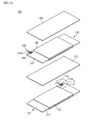
- FIG. 1A is an exploded perspective view illustrating an electrode assembly used in a secondary battery according to an embodiment of the invention
- FIG. 1B is an enlarged view illustrating a portion A of FIG. 1A ;
- FIG. 1C is a cross-sectional view taken along line B-B' of FIG. 1B ;
- FIG. 2 is a partial cross-sectional view illustrating an electrode assembly used in a secondary battery according to another embodiment of the invention
- FIG. 3 is a partial perspective view illustrating an electrode assembly used in a secondary battery according to another embodiment of the invention.
- FIG. 4 is a partial perspective view illustrating an electrode assembly used in a secondary battery according to another embodiment of the invention.
- FIG. 5 is a partial perspective view illustrating an electrode assembly used in a secondary battery according to another embodiment of the invention.
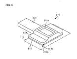
- FIG. 6 is a partial perspective view illustrating an electrode assembly used in a secondary battery according to another embodiment of the invention.
- FIG. 7A is an exploded perspective view illustrating an electrode assembly used in a secondary battery according to another embodiment of the invention.
- FIG. 7B is a perspective view illustrating the assembling state of the electrode assembly of FIG. 5A ;
- FIG. 7C is an enlarged view illustrating a portion C of FIG. 7B ;
- FIG. 8 is a flowchart illustrating a method of fabricating a secondary battery according to an embodiment of the invention.
- FIG. 9 is a flowchart illustrating a method of fabricating a secondary battery according to another embodiment of the invention.
- FIG. 1A is an exploded perspective view illustrating an electrode assembly 100 used in a secondary battery according to an embodiment of the invention.
- FIG. 1B is an enlarged view illustrating a portion A of FIG. 1A .
- FIG. 1C is a cross-sectional view taken along line B-B' of FIG. 1B .
- the electrode assembly 100 used in the secondary battery according to the current embodiment includes a positive electrode plate 110, separators 120, and a negative electrode plate 130.
- the positive electrode plate 110, the separators 120, and the negative electrode plate 130 are sequentially stacked and wound in a jelly roll shape, so as to form the electrode assembly 100.
- the electrode assembly 100 is wound such that a positive electrode tab 113 of the positive electrode plate 110 and a negative electrode tab 133 of the negative electrode plate 130 protrude upward, which will be described later.
- the electrode assembly 100 may be wound such that the positive electrode tab 113 of the positive electrode plate 110 is spaced apart from the negative electrode tab 133 of the negative electrode plate 130.
- the positive electrode plate 110 and the negative electrode plate 130 may be referred to as “electrode plates”, and the positive electrode tab 113 of the positive electrode plate 110 and the negative electrode tab 133 of the negative electrode plate 130 may be referred to as “electrode tabs”.
- the positive electrode plate 110 includes a positive electrode collector 111, positive electrode coating portions 112 disposed on one or more surfaces of the positive electrode collector 111, the positive electrode tab 113 coupled to a surface of the positive electrode collector 111, and a protective member 114 surrounding an end of the positive electrode tab 113.
- the positive electrode collector 111 having a thin layer shape, collects electrons generated through a chemical reaction and delivers the electrons to an external circuit.
- the positive electrode collector 111 may be formed of one of stainless steel, nickel, aluminum, titanium, and alloy thereof, or be formed of an aluminum or stainless steel having a surface treated with carbon, nickel, titanium, or silver.
- the positive electrode coating portions 112 may be formed of material, inserting or extracting lithium ions, such as one or more composite oxides of lithium and at least one of cobalt, manganese, and nickel. Portions of the positive electrode collector 111 extend out of the positive electrode coating portions 112 to form non-coating portions.
- the positive electrode tab 113 is coupled to the non-coating portion of the positive electrode collector 111.
- the positive electrode tab 113 may be coupled to the non-coating portion through laser or resistance welding.
- the positive electrode tab 113 may be formed of aluminum or aluminum alloy, and delivers electrons, collected in the positive electrode collector 111, to an external circuit.
- the protective member 114 surrounds the end of the positive electrode tab 113. Particularly, the end surrounded by the protective member 114 includes the lower edge of the positive electrode tab 113.
- the protective member 114 may be formed of a tape, or be formed through molding.
- the protective member 114 further surrounds corners of the positive electrode tab 113 welded to the positive electrode collector 111.
- the protective member 114 further surrounds at least one portion of the positive electrode tab 113 facing the negative electrode plate 130.
- the protective member 114 insulates the positive electrode tab 113 from the negative electrode plate 130 facing the positive electrode tab 113, and protects the positive electrode collector 111 from the positive electrode tab 113, particularly, from the end of the positive electrode tab 113.
- the protective member 114 surrounds relatively sharp edges and corners of the positive electrode tab 113 to protect the positive electrode collector 111 from the corners of the positive electrode tab 113.
- the protective member 114 may be formed of polymer resin such as polyester having electrical insulating property and elasticity.
- the protective member 114 includes a welding hole 114a passing through an inner surface to another surface. Adhesive may be applied to the lower surface of the protective member 114. In the state where the protective member 114 surrounds the end of the positive electrode tab 113, the protective member 114 is adhered to the positive electrode collector 111, and the positive electrode collector 111 may be exposed through the welding hole 114a. The positive electrode tab 113 may be welded to the positive electrode collector 111 through the welding hole 114a. Although the welding hole 114a has a closed shape as a whole, the welding hole 114a may have an open side to increase a welding area.
- the positive electrode tab 113 is attached to the positive electrode collector 111 in the state where the protective member 114 is attached to the positive electrode tab 113, deformation of the positive electrode collector 111 due to a welding process for the positive electrode tab 113 and an attaching process for the protective member 114 can be reduced. Since the protective member 114 reduces direct contact between the positive electrode collector 111 and the positive electrode tab 113, deformation of the positive electrode collector 111 due to the welding process for the positive electrode tab 113 is prevented.
- the separator 120 is disposed between the positive electrode plate 110 and the negative electrode plate 130.
- the separator 120 prevents a short circuit between the positive electrode plate 110 and the negative electrode plate 130, and provides a passage through which lithium ions pass.
- the separator 120 may be formed of thermoplastic resin such as polyethylene and polypropylene, and have a porous membrane structure. When the inner temperature of the secondary battery reaches the melting point of the thermoplastic resin, the separator 120 having a porous membrane structure is melted to clog pores, so that the separator 120 functions as an insulating film. This prevents lithium ions from passing between the positive electrode plate 110 and the negative electrode plate 130 to stop charging or discharging, so that a current does not flow any more, thus stopping the inner temperature increase of the secondary battery.
- the negative electrode plate 130 includes a negative electrode collector 131, negative electrode coating portions 132 disposed on one or more surfaces of the negative electrode collector 131, the negative electrode tab 133 coupled to a surface of the negative electrode collector 131, and a protective member 134 surrounding an end of the negative electrode tab 133.
- the negative electrode collector 131 has a thin layer shape, like the positive electrode collector 111.
- the negative electrode collector 131 is formed of one of copper and copper alloy.
- the negative electrode coating portions 132 may be formed of material, inserting or extracting lithium ions, such as lithium metal, lithium alloy, and carbon material including crystalline carbon, amorphous carbon, carbon composite, and carbon fiber. Portions of the negative electrode collector 131 extend out of the negative electrode coating portions 132 to form non-coating portions.
- the negative electrode tab 133 is coupled to the non-coating portion of the negative electrode collector 131.
- the negative electrode tab 133 may be coupled to the non-coating portion through laser or resistance welding.
- the negative electrode tab 133 may be formed of copper or nickel, and delivers electrons, collected in the negative electrode collector 131, to an external circuit.
- the protective member 134 surrounds the end of the negative electrode tab 133. Particularly, the end surrounded by the protective member 134 includes the lower edge of the negative electrode tab 133. The protective member 134 further surrounds corners of the negative electrode tab 133 welded to the negative electrode collector 131. In addition, the protective member 134 further surrounds a portion of the negative electrode tab 113 facing the positive electrode plate 110. Thus, the protective member 134 insulates the negative electrode tab 133 from the positive electrode plate 110, and protects the negative electrode collector 131 from the negative electrode tab 133, particularly, from the end of the negative electrode tab 133. That is, the protective member 134 surrounds relatively sharp edges and corners of the negative electrode tab 133 to protect the negative electrode collector 131 from the corners of the negative electrode tab 133.
- the protective member 134 may be formed of polymer resin such as polyester.
- An adhesive layer may be disposed on the lower surface of the protective member 134, and a welding hole 134a is disposed in the protective member 134, like the protective member 114.
- the negative electrode tab 133 may be welded in the state where the negative electrode tab 133 and the protective member 134 are attached to the negative electrode collector 131.
- the protective member 134 protects the negative electrode collector 131 to prevent deformation of the negative electrode collector 131.
- FIG. 2 is a partial cross-sectional view illustrating an electrode assembly used in the secondary battery according to the current embodiment of the invention.
- the electrode assembly used in the secondary battery according to the current embodiment of the invention includes a positive electrode plate 210, a separator (not shown), and a negative electrode plate (not shown).
- the separator is the same as that of the previous embodiment.
- the negative electrode plate has the same configuration as that of the positive electrode plate 210 except for material, but the material is already described in the previous embodiment.
- Like reference numerals denote like element throughout. Hereinafter, different parts of the current embodiment from the previous embodiment will be descried in detail.
- the positive electrode plate 210 includes the positive electrode collector 111, a positive electrode coating portion (not shown), the positive electrode tab 113, and a protective member 214 surrounding the end of the positive electrode tab 113.
- the protective member 214 insulates the positive electrode tab 113 and protects the positive electrode collector 111 from the positive electrode tab 113, particularly, from the end of the positive electrode tab 113.
- the welding hole 114a is disposed in the protective member 214.
- Adhesive may be disposed on the lower surface of the protective member 214.
- the positive electrode tab 113 may be welded to the positive electrode collector 111 through the welding hole 114a.
- the protective member 214 includes a lower protective region 214b is disposed in the lower potion of the positive electrode tab 113.
- the lower protective region 214b surrounds the lower surface disposed at edges of the positive electrode tab 113.
- the protective member 214 protects the positive electrode collector 111 from the corners of the end of the positive electrode tab 113 to prevent damage of the positive electrode collector 111 due to the positive electrode tab 113.
- FIG. 3 is a partial perspective view illustrating the secondary battery according to the current embodiment of the invention.
- an electrode assembly used in the secondary battery includes a positive electrode plate 310, a separator (not shown), and a negative electrode plate (not shown).
- the positive electrode plate 310 includes the positive electrode collector 111, a positive electrode coating portion (not shown), the positive electrode tab 113, and a protective member 314 surrounding the end of the positive electrode tab 113.
- the protective member 314 insulates the positive electrode tab 113 and protects the positive electrode collector 111 from the end of the positive electrode tab 113.
- the welding hole 114a is disposed in the protective member 314. Adhesive may be disposed on the lower surface of the protective member 314. Thus, the positive electrode tab 113 may be welded to the positive electrode collector 111 through the welding hole 114a.
- the protective member 314 has curved surfaces 314c in a portion coupled to the positive electrode collector 111. That is, the corners of the end of the protective member 314 contacting the positive electrode collector 111 are replaced with the curved surfaces 314c. Thus, the protective member 314 protects the positive electrode collector 111 from the end of the positive electrode tab 113 and from the corners of the end of the protective member 314.
- FIG. 4 is a partial perspective view illustrating the secondary battery according to the current embodiment of the invention.
- an electrode assembly used in the secondary battery includes a positive electrode plate 410, a separator (not shown), and a negative electrode plate (not shown).
- the positive electrode plate 410 includes the positive electrode collector 111, a positive electrode coating portion (not shown), the positive electrode tab 113, and a protective member 414 surrounding the end of the positive electrode tab 113.
- the protective member 414 surrounds only an end disposed in the area of the positive electrode tab 113 coupled to the positive electrode collector 111. That is, the protective member 414 is disposed on the inside of the positive electrode collector 111 to expose a portion of the positive electrode tab 113 overlapping the positive electrode collector 111. Thus, the positive electrode tab 113 may be welded to the positive electrode collector 111 through the exposed portion.
- the protective member 414 may include a welding hole, which may increase a welding area.
- FIG. 5 is a partial perspective view illustrating an electrode assembly used in the secondary battery according to the current embodiment of the invention.
- the electrode assembly used in the secondary battery includes a positive electrode plate 510, a separator (not shown), and a negative electrode plate (not shown).
- the positive electrode plate 510 includes the positive electrode collector 111, a positive electrode coating portion (not shown), a positive electrode tab 513, and protective members 514 and 515 surrounding an end of the positive electrode tab 513.
- the positive electrode tab 513 is coupled to the non-coating portion of the positive electrode collector 111.
- the positive electrode tab 113 may be coupled to the non-coating portion through laser or resistance welding. First, the lower surface of the positive electrode tab 513 is surrounded by the protective member 515, then, the positive electrode tab 513 is placed on the non-coating portion of the positive electrode collector 111, and then, is coupled to the non-coating portion through welding.
- the positive electrode tab 513 is disposed to be spaced apart from the upper surface of the non-coating portion by the thickness of the protective member 515, and then, is coupled to the non-coating portion through welding.
- the protective members 514 and 515 surround the end of the positive electrode tab 513.
- the protective members 514 and 515 include a first protective member (also denoted by 514) disposed on the upper portion of the positive electrode tab 513, and a second protective member (also denoted by 515) disposed on the lower portion of the positive electrode tab 513.
- the positive electrode tab 513 is placed on the upper portion of the second protective member 515, then, the upper portion of the positive electrode tab 513 is covered with the first protective member 514, and then, the positive electrode tab 513 is placed on the upper portion of the positive electrode collector 111.
- the first and second protective members 514 and 515 are coupled to each other through adhesive with the positive electrode tab 513 therebetween.
- the positive electrode tab 513 is welded through a welding hole 514a formed in the first protective member 514, and the positive electrode tab 513 is coupled to the non-coating portion through a welding hole 515a of the second protective member 515.
- the lower surface of the second protective member 515 need not be adhered to the non-coating portion of the positive electrode collector 111. This is because the second protective member 515 may be coupled to the non-coating portion of the positive electrode collector 111 during the welding.
- the welding may be performed after the lower of the second protective member 515 is adhered to the non-coating portion, to dispose the first and second protective members 514 and 515 at an exact position.
- FIG. 6 is a partial perspective view illustrating an electrode assembly used in the secondary battery according to the current embodiment of the invention.
- the electrode assembly used in the secondary battery includes a positive electrode plate 610, a separator (not shown), and a negative electrode plate (not shown).
- the positive electrode plate 610 includes the positive electrode collector 111, a positive electrode coating portion (not shown), the positive electrode tab 513, and protective members 614 and 615 surrounding an end of the positive electrode tab 513.
- the protective members 614 and 615 are the same as the protective members 514 and 515 of the embodiment as described above. However, portions of the protective members 614 and 615 coupled to the positive electrode collector 111 have curved surfaces 614b and 615b. That is, the protective members 614 and 615 have the curved surfaces 614b and 615b instead of the edges of the ends contacting the positive electrode collector 111. Thus, since the edges are removed from the protective members 614 and 615, the positive electrode collector 111 is protected from the ends of the positive electrode tab 513 and the edges of the ends of the protective members 614 and 615.
- FIG. 7A is an exploded perspective view illustrating an electrode assembly 500 used in the secondary battery according to the current embodiment of the invention.
- FIG. 7B is a perspective view illustrating the assembling state of the electrode assembly 500.
- FIG. 7C is an enlarged view illustrating a portion C of FIG. 7B .
- the electrode assembly 700 used in the second battery according to the current embodiment includes positive electrode plates 710, separators 720, and negative electrode plates 730.
- the electrode assembly 700 has a stack structure. That is, the positive electrode plates 710, the separators 720, and the negative electrode plates 730 are sequentially stacked to form the electrode assembly 700.
- Each of the positive electrode plates 710 includes the positive electrode collector 111, positive electrode coating portions 712 disposed on one or more surfaces of the positive electrode collector 111, a positive electrode tab 713 coupled to a surface of the positive electrode collector 111, a protective member 714 surrounding a first end of the positive electrode tab 713, and a positive terminal 715 disposed at a second end of the positive electrode tab 713.
- a first surface of the positive electrode collector 111 except for the region to which the positive electrode tab 713 is coupled, and a second surface of the positive electrode collector 111 are entirely coated with the positive electrode coating portions 712.
- the portion of the positive electrode collector 111 disposed out of the positive electrode coating portions 712 forms a non-coating portion.
- the positive electrode coating portions 712 may be formed of material, inserting or extracting lithium ions, such as one or more composite oxides of lithium and at least one of cobalt, manganese, and nickel.
- Horizontal positions of the positive electrode plates 710, where the positive electrode coating portions 712 are disposed, are the same, and thus, horizontal positions of the positive electrode plates 710, where the non-coating portions are disposed, are the same.
- the positive electrode tab 713 may be formed of aluminum, and is coupled to the non-coating portion of the positive electrode collector 111.
- the positive electrode tabs 713 may be welded to the same horizontal positions of the non-coating portions, respectively. That is, the positive electrode tabs 713 may be arrayed along a vertical straight line.
- the protective member 714 surrounding an end of the positive electrode tab 713, insulates the positive electrode tab 713 and protects the positive electrode collector 111 from the end of the positive electrode tab 713.
- a welding hole 714a is disposed in the protective member 714.
- the positive electrode tab 713 may be welded to the positive electrode collector 111 through the welding hole 714a.
- the protective member 714 protects the positive electrode collector 111 to prevent deformation of the positive electrode collector 111.
- the positive terminal 715 is formed by bending the second end of the positive electrode tab 713. That is, the uppermost or lowermost one of the positive electrode tabs 713 of the stacked positive electrode plates 710 is bent to surround the others of the positive electrode tabs 713, and the welding process is performed to form the positive terminal 715. That is, since the positive terminal 715 is formed by bending the positive electrode tab 713 without an additional structure, costs of the secondary battery are reduced, and more tight coupling of the positive terminal 715 is achieved.
- the positive electrode tab 713 forming the positive terminal 715 may have a larger length and a larger thickness than those of the other positive electrode tabs 713.
- the separators 720 are stacked between the positive electrode plates 710 and the negative electrode plates 730.
- the separators 720 prevent a short circuit between the positive electrode plate 710 and the negative electrode plate 730, and allow the passing of lithium ions.
- Each of the negative electrode plates 730 includes the negative electrode collector 131, negative electrode coating portions 732 disposed on one or more surfaces of the negative electrode collector 131, a negative electrode tab 733 coupled to a first surface of the negative electrode collector 131, a protective member 734 surrounding a first end of the negative electrode tab 733, and a negative terminal 735 disposed in a second end of the negative electrode tab 733.
- the negative electrode coating portions 732 are formed on one or more surfaces of the negative electrode collector 131 through coating. For example, the first surface of the negative electrode collector 131 except for the region to which the negative electrode tab 733 is coupled, and a second surface of the negative electrode collector 131 are entirely coated with the negative electrode coating portions 732. The portion of the negative electrode collector 131 disposed out of the negative electrode coating portions 732 forms a non-coating portion. Thus, the amount of coating portions formed on the negative electrode plate 730 is maximized, and the capacity of the secondary battery is increased. Horizontal positions of the negative electrode plates 730, where the negative electrode coating portions 732 are disposed, are the same. Horizontal positions of the negative electrode plates 730, where the non-coating portions are disposed, are the same.
- the negative electrode tabs 733 may be formed of nickel, and are coupled to the non-coating portions of the negative electrode collector 131. Horizontal positions of the negative electrode plates 730, where the negative electrode tabs 733 are disposed, are the same. That is, the negative electrode tabs 733 are arrayed along a vertical straight line. The negative electrode tabs 733 are horizontally spaced apart from the positive electrode tabs 713.
- the protective member 734 surrounding the first end of the negative electrode tab 733, insulates the negative electrode tab 733, and protects the negative electrode collector 131 from the first end of the negative electrode tab 733.
- a welding hole 734a is disposed in the protective member 734.
- the negative electrode tab 733 may be welded to the negative electrode collector 131 through the welding hole 734a.
- the protective member 734 protects the negative electrode collector 131 to prevent deformation of the negative electrode collector 131.
- the negative terminal 735 is formed by bending the second end of the negative electrode tab 733. That is, the uppermost or lowermost one of the negative electrode tabs 733 of the stacked negative electrode plates 730 is bent to surround the others of the negative electrode tabs 733, and the welding process is performed to form the negative terminal 735. That is, since the negative terminal 735 is formed by bending the negative electrode tab 733 without an additional structure, costs of the secondary battery are reduced, and more tight coupling of the negative terminal 735 is achieved.
- the negative electrode tab 733 forming the negative terminal 735 may have a larger length and a larger thickness than those of the other negative electrode tabs 733.
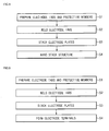
- FIG. 8 is a flowchart illustrating the method of fabricating a secondary battery according to the current embodiment of the invention.
- the method of fabricating a secondary battery includes an operation S of preparing electrode tabs and protective members, an operation S2 of welding the electrode tabs, a stacking operation S3, and a winding operation S4.
- the operations S1 through S4 of FIG. 8 will now be described with reference to FIGS. 1A through 1C .
- the positive electrode tab 113, the protective member 114 surrounding the positive electrode tab 113, the negative electrode tab 133, and the protective member 134 surrounding the negative electrode tab 133 are prepared.
- the protective member 114 surrounds the end of the positive electrode tab 113.
- the protective member 114 may be formed of a tape, or be formed through molding.
- the welding hole 114a is disposed in the protective member 114 to expose a portion of the positive electrode tab 113.
- the protective member 134 surrounding the negative electrode tab 133 has the similar configuration to that of the protective member 114.
- the lower surfaces of the protective members 114 and 134 may be provided with adhesive members to increase adhering force to the positive electrode collector 111 and the negative electrode collector 131.
- the positive electrode tab 113 is welded to the positive electrode collector 111, and the negative electrode tab 133 is welded to the negative electrode collector 131.
- the positive electrode tab 113 is welded through the welding hole 114a of the protective member 114 in the state where the positive electrode tab 113 together with the protective member 114 is disposed on the non-coating portion of the positive electrode collector 111.
- the negative electrode tab 133 is welded through the welding hole 134a of the protective member 134 in the state where the negative electrode tab 133 together with the protective member 134 is disposed on the non-coating portion of the negative electrode collector 131.
- the protective members 114 and 134 and the welding of the positive electrode tab 113 and the negative electrode tab 133 are performed in a single process, deformation of the positive electrode collector 111 and the negative electrode collector 131 can be reduced. Furthermore, since the positive electrode tab 113 and the negative electrode tab 133 are welded through the welding holes 114a and 134a, the protective member 114 and 134 protect the positive electrode collector 111 and the negative electrode collector 131 to prevent deformation due to the welding.
- the positive electrode plate 110 coupled with the positive electrode tab 113 and the protective member 114, and the negative electrode plate 130 coupled with the negative electrode tab 133 and the protective member 134 are stacked.
- the separator 120 is stacked between the positive electrode plate 110 and the negative electrode plate 130 on an outside of at least one of the positive electrode plate 110 and the negative electrode plate 130.
- the separator 120 prevents a short circuit between the positive electrode plate 110 and the negative electrode plate 130 and allows the passing of lithium ions.
- a stack structure of the positive electrode plate 110, the separator 120, and the negative electrode plate 130 is wound.
- the electrode assembly 100 in which the positive electrode plate 110, the separator 120, and the negative electrode plate 130 are sequentially stacked is wound in a jelly roll shape.
- the positive electrode tab 113 and the negative electrode tab 133 of the electrode assembly 100 protrude upward.
- the positive electrode tab 113 of the positive electrode plate 110 may be spaced apart from the negative electrode tab 133 of the negative electrode plate 130.
- the electrode assembly 100 is inserted into a case or a pouch, and electrolyte is injected into the case or the pouch to form a secondary battery.
- FIG. 9 is a flowchart illustrating the method of fabricating a secondary battery according to the current embodiment of the invention.
- the method of fabricating a secondary battery includes an operation S1 of preparing electrode tabs and protective members, an operation S2 of welding the electrode tabs, a stacking operation S3, and an operation S4 of forming electrode terminals.
- the operations S1 through S4 of FIG. 9 will now be described with reference to FIGS. 7A through 7C .
- the positive electrode tab 713, the protective member 714 surrounding the positive electrode tab 713, the negative electrode tab 733, and the protective member 734 surrounding the negative electrode tab 733 are prepared.
- the protective member 714 surrounds the end of the positive electrode tab 713.
- the welding hole 714a is disposed in the protective member 714 to expose a portion of the positive electrode tab 713.
- the protective member 734 surrounding the negative electrode tab 733 has the similar configuration to that of the protective member 714.
- the positive electrode tab 713 is welded to the positive electrode collector 111, and the negative electrode tab 733 is welded to the negative electrode collector 131.
- the positive electrode tab 713 is welded through the welding hole 714a of the protective member 714 in the state where the positive electrode tab 713 together with the protective member 714 is disposed on the non-coating portion of the positive electrode collector 111.
- the negative electrode tab 733 is welded through the welding hole 734a of the protective member 734 in the state where the negative electrode tab 733 together with the protective member 734 is disposed on the non-coating portion of the negative electrode collector 131.
- the positive electrode plate 710 coupled with the positive electrode tab 713 and the protective member 714, and the negative electrode plate 730 coupled with the negative electrode tab 733 and the protective member 734 are stacked.
- the separator 720 is stacked between the positive electrode plate 710 and the negative electrode plate 730 on outsides of the positive electrode plate 710 and the negative electrode plate 730.
- each of the positive electrode plate 710, the separator 120, and the negative electrode plate 730 is provided in plurality.
- Horizontal positions of the positive electrode plates 710, where the positive electrode tabs 713 are disposed, are the same. That is, the positive electrode tabs 713 are arrayed along a vertical straight line.
- Horizontal positions of the negative electrode plates 730, where the negative electrode tabs 733 are disposed, are the same. That is, the negative electrode tabs 733 are arrayed along a vertical straight line.
- the positive electrode tab 713 is bent to form the positive terminal 715
- the negative electrode tab 733 is bent to form the negative terminal 735.
- the positive terminal 715 is formed by bending the uppermost or lowermost one of the positive electrode tabs 713, and by welding the uppermost or lowermost positive electrode tab 713 with the other positive electrode tabs 713 in the uppermost or lowermost positive electrode tab 713. That is, since the positive terminal 715 is formed by bending and welding the positive electrode tab 713 without an additional structure, costs of the secondary battery are reduced, and more tight coupling of the positive terminal 715 is achieved.
- the negative terminal 735 may be formed using the negative electrode tabs 733 according to the same method as that of the positive terminal 715.
- the protective members are coupled to the positive electrode tab and the negative electrode tab and disposed on the collectors, and the welding processes are performed, thereby reducing deformation of the collectors due to the welding processes and the attaching of the protective members.
- the welding process is performed at the position exposed out of the protective member, so that the protective member protects the collector, thereby preventing deformation of the collector during the welding process.
Landscapes
- Chemical & Material Sciences (AREA)
- Chemical Kinetics & Catalysis (AREA)
- Electrochemistry (AREA)
- General Chemical & Material Sciences (AREA)
- Engineering & Computer Science (AREA)
- Manufacturing & Machinery (AREA)
- Secondary Cells (AREA)
- Connection Of Batteries Or Terminals (AREA)
Abstract
Description
- The present invention relates to a secondary battery and a method of fabricating the secondary battery.
- With the trend for lightweight and high functionality portable electronic appliances such as video cameras, mobile phones, and portable computers, research is actively being carried out on secondary batteries to function as power sources of the portable appliances. Secondary batteries include nickel-cadmium batteries, nickel-hydrogen batteries, nickel-zinc batteries, and lithium ion batteries. Of these, the lithium ion secondary batteries are particularly adapted for miniaturization and high capacity. In addition, since the lithium ion secondary batteries have high operation voltages and high energy density per unit weight, such batteries are widely used in high-end electronic appliances.
- A lithium ion battery typically takes the form of a battery pack that includes a battery cell, a circuit module, and a cover. The battery cell includes an electrode assembly, a can, and a cap assembly. The electrode assembly includes a positive electrode plate, a negative electrode plate, and a separator. The can accommodates the electrode assembly. The cap assembly seals the can. The circuit module includes a protective circuit device and is coupled to the battery cell. The cover covers the circuit module.
- The present invention sets out to provide a secondary battery and a method of fabricating the secondary battery, which substantially overcome one or more problems due to the limitations and disadvantages of the related art.
- In particular, the invention sets out to provide a secondary battery and a method of fabricating the secondary battery which prevent an electrode plate from being damaged when an electrode tab is coupled to the electrode plate.
- At least one of the above and other features and advantages may be realized by providing a secondary battery including: an electrode assembly including an electrode plate and a separator, the electrode plate including a positive electrode plate coupled with a positive electrode tab and a negative electrode plate coupled with a negative electrode tab, wherein at least one of the positive electrode tab and the negative electrode tab is coupled to a non-coating portion of the electrode plate, to which a coating portion is not applied, has an end surround by a protective member, and a region exposed out of the protective member and coupled to the non-coating portion.
- The protective member may be provided with a welding hole configured to weld one of the positive electrode tab and the negative electrode tab.
- An adhesive may be disposed on a lower surface of the protective member to adhere the protective member to a collector of the electrode plate.
- The protective member may surround a lower surface disposed at an edge of one of the positive electrode tab and the negative electrode tab.
The protective member may include: a first protective member disposed on an upper portion of at least one of the positive electrode tab and the negative electrode tab; and a second protective member coupled to a lower portion of the first protective member to surround at least one of the positive electrode tab and the negative electrode tab between the first and second protective members. The protective member may be formed of a tape, or be formed through molding. - The protective member may have a curved surface at a corner coupled to the non-coating portion.
- The electrode assembly may have a jelly roll shape in which the positive electrode plate, the separator, and the negative electrode plate are stacked and wound, and the positive electrode tab may be spaced apart from the negative electrode tab.
- Each of the positive electrode plate, the separator, and the negative electrode plate may be provided in plurality, the electrode assembly may have a stack structure in which the positive electrode plates, the separators, and the negative electrode plates are stacked, and the positive electrode tabs of the positive electrode plates and the negative electrode tabs of the negative electrode plates may be collected according to poles, so as to respectively form electrode terminals.
- The electrode terminal of the positive electrode tabs may be formed by bending one of the positive electrode tabs to surround the others of the positive electrode tabs, and the electrode terminal of the negative electrode tabs may be formed by bending one of the negative electrode tabs to surround the others of the negative electrode tabs.
- The bent tabs may be the uppermost or lowermost one of the positive electrode tabs and the uppermost or lowermost one of the negative electrode tabs.
- The bent tab may have a length greater than those of the others of the tabs.
- The bent tab may have a thickness greater than those of the others of the tabs.
- At least one of the above and other features and advantages may be realized by providing a method of fabricating a secondary battery including an electrode assembly including an electrode plate and a separator, the electrode plate including a positive electrode plate coupled with a positive electrode tab and a negative electrode plate coupled with a negative electrode tab, the method including: preparing the positive electrode tab, the negative electrode tab, and a protective member surrounding an end of at least one of the positive electrode tab and the negative electrode tab; welding at least one of the positive electrode tab and the negative electrode tab exposed out of the protective member to a non-coating portion of the electrode plate; and sequentially stacking the positive electrode plate, the separator, and the negative electrode plate.
- In the preparing of the electrode tabs and the protective member, a welding hole may be formed in an upper surface of the protective member.
- The welding of the electrode tab may be performed at an upper portion of the protective member through the welding hole.
In the preparing of the electrode tabs and the protective member, the protective member may be formed of a tape, or be formed through molding. - In the preparing of the electrode tabs and the protective member, the protective member may have a curved surface at a corner of a portion surrounding the end of at least one of the positive electrode tab and the negative electrode tab.
In the preparing of the electrode tabs and the protective member, the protective member may surround a lower surface disposed at an edge of at least one of the positive and negative electrode tabs.
In the preparing of the electrode tabs and the protective member, the protective member may include: a first protective member disposed on an upper portion of at least one of the positive electrode tab and the negative electrode tab; and a second protective member disposed on a lower portion of the first protective member to surround at least one of the positive electrode tab and the negative electrode tab between the first and second protective members. - The method may further include wounding the positive electrode plate, the negative electrode plate, and the separator to form the electrode assembly after the stacking of the electrode plates and the separator.
- The method may further include, after the stacking of the electrode plates and the separator, preparing each of the positive electrode plate, the negative electrode plate, and the separator in plurality to stack the positive electrode plates, the separators, and the negative electrode plates; and collecting and welding the positive electrode tabs of the positive electrode plates and the negative electrode tabs of the negative electrode plates according to poles, so as to respectively form electrode terminals.
- The forming of the electrode terminals may include: bending one of the positive electrode tabs to surround the others of the positive electrode tabs; and bending one of the negative electrode tabs to surround the others of the negative electrode tabs.
- The forming of the electrode terminals may include bending the uppermost or lowermost one of the positive electrode tabs and the uppermost or lowermost one of the negative electrode tabs.
- The forming of the electrode terminals may include bending the positive electrode tab having a length greater than those of the others of the positive electrode tabs and the negative electrode tab having a length greater than those of the others of the negative electrode tabs.
- The forming of the electrode terminals may include bending the positive electrode tab having a thickness greater than those of the others of the positive electrode tabs and the negative electrode tab having a thickness greater than those of the others of the negative electrode tabs.
- The above and other features of the invention are set out in the appended claims.
- The above and other features and advantages will become more apparent to those of ordinary skill in the art upon making reference to the following description of embodiments of the invention with reference to the attached drawings, in which:
-
FIG. 1A is an exploded perspective view illustrating an electrode assembly used in a secondary battery according to an embodiment of the invention; -
FIG. 1B is an enlarged view illustrating a portion A ofFIG. 1A ; -
FIG. 1C is a cross-sectional view taken along line B-B' ofFIG. 1B ; -
FIG. 2 is a partial cross-sectional view illustrating an electrode assembly used in a secondary battery according to another embodiment of the invention; -
FIG. 3 is a partial perspective view illustrating an electrode assembly used in a secondary battery according to another embodiment of the invention; -
FIG. 4 is a partial perspective view illustrating an electrode assembly used in a secondary battery according to another embodiment of the invention; -
FIG. 5 is a partial perspective view illustrating an electrode assembly used in a secondary battery according to another embodiment of the invention; -
FIG. 6 is a partial perspective view illustrating an electrode assembly used in a secondary battery according to another embodiment of the invention; -
FIG. 7A is an exploded perspective view illustrating an electrode assembly used in a secondary battery according to another embodiment of the invention; -
FIG. 7B is a perspective view illustrating the assembling state of the electrode assembly ofFIG. 5A ; -
FIG. 7C is an enlarged view illustrating a portion C ofFIG. 7B ; -
FIG. 8 is a flowchart illustrating a method of fabricating a secondary battery according to an embodiment of the invention; and -
FIG. 9 is a flowchart illustrating a method of fabricating a secondary battery according to another embodiment of the invention. - Embodiments of the invention will now be described more fully hereinafter with reference to the accompanying drawings; however, they may be embodied in different forms and should not be construed as limited to the embodiments set forth herein. Rather, these embodiments are provided so that this disclosure will be thorough and complete, and will fully convey the scope of the invention to those skilled in the art. Like reference numerals denote like elements throughout.
-
FIG. 1A is an exploded perspective view illustrating anelectrode assembly 100 used in a secondary battery according to an embodiment of the invention.FIG. 1B is an enlarged view illustrating a portion A ofFIG. 1A .FIG. 1C is a cross-sectional view taken along line B-B' ofFIG. 1B . - Referring to
FIGS. 1A through 1C , theelectrode assembly 100 used in the secondary battery according to the current embodiment includes apositive electrode plate 110,separators 120, and anegative electrode plate 130. - The
positive electrode plate 110, theseparators 120, and thenegative electrode plate 130 are sequentially stacked and wound in a jelly roll shape, so as to form theelectrode assembly 100. Theelectrode assembly 100 is wound such that apositive electrode tab 113 of thepositive electrode plate 110 and anegative electrode tab 133 of thenegative electrode plate 130 protrude upward, which will be described later. In this case, theelectrode assembly 100 may be wound such that thepositive electrode tab 113 of thepositive electrode plate 110 is spaced apart from thenegative electrode tab 133 of thenegative electrode plate 130. - Hereinafter, the
positive electrode plate 110 and thenegative electrode plate 130 may be referred to as "electrode plates", and thepositive electrode tab 113 of thepositive electrode plate 110 and thenegative electrode tab 133 of thenegative electrode plate 130 may be referred to as "electrode tabs". - The
positive electrode plate 110 includes apositive electrode collector 111, positiveelectrode coating portions 112 disposed on one or more surfaces of thepositive electrode collector 111, thepositive electrode tab 113 coupled to a surface of thepositive electrode collector 111, and aprotective member 114 surrounding an end of thepositive electrode tab 113. - The
positive electrode collector 111, having a thin layer shape, collects electrons generated through a chemical reaction and delivers the electrons to an external circuit. Thepositive electrode collector 111 may be formed of one of stainless steel, nickel, aluminum, titanium, and alloy thereof, or be formed of an aluminum or stainless steel having a surface treated with carbon, nickel, titanium, or silver. - One or more surfaces of the
positive electrode collector 111 are coated with the positiveelectrode coating portions 112. The positiveelectrode coating portions 112 may be formed of material, inserting or extracting lithium ions, such as one or more composite oxides of lithium and at least one of cobalt, manganese, and nickel. Portions of thepositive electrode collector 111 extend out of the positiveelectrode coating portions 112 to form non-coating portions. - The
positive electrode tab 113 is coupled to the non-coating portion of thepositive electrode collector 111. Thepositive electrode tab 113 may be coupled to the non-coating portion through laser or resistance welding. Thepositive electrode tab 113 may be formed of aluminum or aluminum alloy, and delivers electrons, collected in thepositive electrode collector 111, to an external circuit. - The
protective member 114 surrounds the end of thepositive electrode tab 113. Particularly, the end surrounded by theprotective member 114 includes the lower edge of thepositive electrode tab 113. Theprotective member 114 may be formed of a tape, or be formed through molding. Theprotective member 114 further surrounds corners of thepositive electrode tab 113 welded to thepositive electrode collector 111. In addition, theprotective member 114 further surrounds at least one portion of thepositive electrode tab 113 facing thenegative electrode plate 130. Thus, theprotective member 114 insulates thepositive electrode tab 113 from thenegative electrode plate 130 facing thepositive electrode tab 113, and protects thepositive electrode collector 111 from thepositive electrode tab 113, particularly, from the end of thepositive electrode tab 113. That is, theprotective member 114 surrounds relatively sharp edges and corners of thepositive electrode tab 113 to protect thepositive electrode collector 111 from the corners of thepositive electrode tab 113. To this end, theprotective member 114 may be formed of polymer resin such as polyester having electrical insulating property and elasticity. - The
protective member 114 includes awelding hole 114a passing through an inner surface to another surface. Adhesive may be applied to the lower surface of theprotective member 114. In the state where theprotective member 114 surrounds the end of thepositive electrode tab 113, theprotective member 114 is adhered to thepositive electrode collector 111, and thepositive electrode collector 111 may be exposed through thewelding hole 114a. Thepositive electrode tab 113 may be welded to thepositive electrode collector 111 through thewelding hole 114a. Although thewelding hole 114a has a closed shape as a whole, thewelding hole 114a may have an open side to increase a welding area. - Thus, since the
positive electrode tab 113 is attached to thepositive electrode collector 111 in the state where theprotective member 114 is attached to thepositive electrode tab 113, deformation of thepositive electrode collector 111 due to a welding process for thepositive electrode tab 113 and an attaching process for theprotective member 114 can be reduced. Since theprotective member 114 reduces direct contact between thepositive electrode collector 111 and thepositive electrode tab 113, deformation of thepositive electrode collector 111 due to the welding process for thepositive electrode tab 113 is prevented. - The
separator 120 is disposed between thepositive electrode plate 110 and thenegative electrode plate 130. Theseparator 120 prevents a short circuit between thepositive electrode plate 110 and thenegative electrode plate 130, and provides a passage through which lithium ions pass. For example, theseparator 120 may be formed of thermoplastic resin such as polyethylene and polypropylene, and have a porous membrane structure. When the inner temperature of the secondary battery reaches the melting point of the thermoplastic resin, theseparator 120 having a porous membrane structure is melted to clog pores, so that theseparator 120 functions as an insulating film. This prevents lithium ions from passing between thepositive electrode plate 110 and thenegative electrode plate 130 to stop charging or discharging, so that a current does not flow any more, thus stopping the inner temperature increase of the secondary battery. - The
negative electrode plate 130 includes anegative electrode collector 131, negativeelectrode coating portions 132 disposed on one or more surfaces of thenegative electrode collector 131, thenegative electrode tab 133 coupled to a surface of thenegative electrode collector 131, and a protective member 134 surrounding an end of thenegative electrode tab 133. - The
negative electrode collector 131 has a thin layer shape, like thepositive electrode collector 111. Thenegative electrode collector 131 is formed of one of copper and copper alloy. - One or more surfaces of the
negative electrode collector 131 are coated with the negativeelectrode coating portions 132. The negativeelectrode coating portions 132 may be formed of material, inserting or extracting lithium ions, such as lithium metal, lithium alloy, and carbon material including crystalline carbon, amorphous carbon, carbon composite, and carbon fiber. Portions of thenegative electrode collector 131 extend out of the negativeelectrode coating portions 132 to form non-coating portions. - The
negative electrode tab 133 is coupled to the non-coating portion of thenegative electrode collector 131. Thenegative electrode tab 133 may be coupled to the non-coating portion through laser or resistance welding. For example, thenegative electrode tab 133 may be formed of copper or nickel, and delivers electrons, collected in thenegative electrode collector 131, to an external circuit. - The protective member 134 surrounds the end of the
negative electrode tab 133. Particularly, the end surrounded by the protective member 134 includes the lower edge of thenegative electrode tab 133. The protective member 134 further surrounds corners of thenegative electrode tab 133 welded to thenegative electrode collector 131. In addition, the protective member 134 further surrounds a portion of thenegative electrode tab 113 facing thepositive electrode plate 110. Thus, the protective member 134 insulates thenegative electrode tab 133 from thepositive electrode plate 110, and protects thenegative electrode collector 131 from thenegative electrode tab 133, particularly, from the end of thenegative electrode tab 133. That is, the protective member 134 surrounds relatively sharp edges and corners of thenegative electrode tab 133 to protect thenegative electrode collector 131 from the corners of thenegative electrode tab 133. To this end, the protective member 134 may be formed of polymer resin such as polyester. An adhesive layer may be disposed on the lower surface of the protective member 134, and awelding hole 134a is disposed in the protective member 134, like theprotective member 114. Thenegative electrode tab 133 may be welded in the state where thenegative electrode tab 133 and the protective member 134 are attached to thenegative electrode collector 131. - Thus, like the
positive electrode tab 113, deformation of thenegative electrode collector 131 due to two stages of a welding process for thenegative electrode tab 133 and an attaching process for the protective member 134 can be reduced. When thenegative electrode tab 133 is welded, the protective member 134 protects thenegative electrode collector 131 to prevent deformation of thenegative electrode collector 131. - Hereinafter, the configuration of a secondary battery will now be described according to another embodiment of the invention.
-
FIG. 2 is a partial cross-sectional view illustrating an electrode assembly used in the secondary battery according to the current embodiment of the invention. - Referring to
FIG. 2 , the electrode assembly used in the secondary battery according to the current embodiment of the invention includes apositive electrode plate 210, a separator (not shown), and a negative electrode plate (not shown). The separator is the same as that of the previous embodiment. The negative electrode plate has the same configuration as that of thepositive electrode plate 210 except for material, but the material is already described in the previous embodiment. Like reference numerals denote like element throughout. Hereinafter, different parts of the current embodiment from the previous embodiment will be descried in detail. - The
positive electrode plate 210 includes thepositive electrode collector 111, a positive electrode coating portion (not shown), thepositive electrode tab 113, and aprotective member 214 surrounding the end of thepositive electrode tab 113. - The
protective member 214 insulates thepositive electrode tab 113 and protects thepositive electrode collector 111 from thepositive electrode tab 113, particularly, from the end of thepositive electrode tab 113. - The
welding hole 114a is disposed in theprotective member 214. Adhesive may be disposed on the lower surface of theprotective member 214. Thus, thepositive electrode tab 113 may be welded to thepositive electrode collector 111 through thewelding hole 114a. - The
protective member 214 includes a lowerprotective region 214b is disposed in the lower potion of thepositive electrode tab 113. The lowerprotective region 214b surrounds the lower surface disposed at edges of thepositive electrode tab 113. Thus, theprotective member 214 protects thepositive electrode collector 111 from the corners of the end of thepositive electrode tab 113 to prevent damage of thepositive electrode collector 111 due to thepositive electrode tab 113. - Hereinafter, the configuration of a secondary battery will now be described according to another embodiment of the invention.
-
FIG. 3 is a partial perspective view illustrating the secondary battery according to the current embodiment of the invention. - Referring to
FIG. 3 , an electrode assembly used in the secondary battery includes apositive electrode plate 310, a separator (not shown), and a negative electrode plate (not shown). - The
positive electrode plate 310 includes thepositive electrode collector 111, a positive electrode coating portion (not shown), thepositive electrode tab 113, and aprotective member 314 surrounding the end of thepositive electrode tab 113. - The
protective member 314 insulates thepositive electrode tab 113 and protects thepositive electrode collector 111 from the end of thepositive electrode tab 113. - The
welding hole 114a is disposed in theprotective member 314. Adhesive may be disposed on the lower surface of theprotective member 314. Thus, thepositive electrode tab 113 may be welded to thepositive electrode collector 111 through thewelding hole 114a. - The
protective member 314 hascurved surfaces 314c in a portion coupled to thepositive electrode collector 111. That is, the corners of the end of theprotective member 314 contacting thepositive electrode collector 111 are replaced with thecurved surfaces 314c. Thus, theprotective member 314 protects thepositive electrode collector 111 from the end of thepositive electrode tab 113 and from the corners of the end of theprotective member 314. - Hereinafter, the configuration of a secondary battery will now be described according to another embodiment of the invention.
-
FIG. 4 is a partial perspective view illustrating the secondary battery according to the current embodiment of the invention. - Referring to
FIG. 4 , an electrode assembly used in the secondary battery includes apositive electrode plate 410, a separator (not shown), and a negative electrode plate (not shown). - The
positive electrode plate 410 includes thepositive electrode collector 111, a positive electrode coating portion (not shown), thepositive electrode tab 113, and aprotective member 414 surrounding the end of thepositive electrode tab 113. - The
protective member 414 surrounds only an end disposed in the area of thepositive electrode tab 113 coupled to thepositive electrode collector 111. That is, theprotective member 414 is disposed on the inside of thepositive electrode collector 111 to expose a portion of thepositive electrode tab 113 overlapping thepositive electrode collector 111. Thus, thepositive electrode tab 113 may be welded to thepositive electrode collector 111 through the exposed portion. Although not shown, theprotective member 414 may include a welding hole, which may increase a welding area. - Hereinafter, the configuration of a secondary battery will now be described according to another embodiment of the invention.
-
FIG. 5 is a partial perspective view illustrating an electrode assembly used in the secondary battery according to the current embodiment of the invention. - Referring to
FIG. 5 , the electrode assembly used in the secondary battery includes apositive electrode plate 510, a separator (not shown), and a negative electrode plate (not shown). - The
positive electrode plate 510 includes thepositive electrode collector 111, a positive electrode coating portion (not shown), apositive electrode tab 513, andprotective members positive electrode tab 513. - The
positive electrode tab 513 is coupled to the non-coating portion of thepositive electrode collector 111. Thepositive electrode tab 113 may be coupled to the non-coating portion through laser or resistance welding. First, the lower surface of thepositive electrode tab 513 is surrounded by theprotective member 515, then, thepositive electrode tab 513 is placed on the non-coating portion of thepositive electrode collector 111, and then, is coupled to the non-coating portion through welding. Thepositive electrode tab 513 is disposed to be spaced apart from the upper surface of the non-coating portion by the thickness of theprotective member 515, and then, is coupled to the non-coating portion through welding. - The
protective members positive electrode tab 513. Theprotective members positive electrode tab 513, and a second protective member (also denoted by 515) disposed on the lower portion of thepositive electrode tab 513. - The
positive electrode tab 513 is placed on the upper portion of the secondprotective member 515, then, the upper portion of thepositive electrode tab 513 is covered with the firstprotective member 514, and then, thepositive electrode tab 513 is placed on the upper portion of thepositive electrode collector 111. The first and secondprotective members positive electrode tab 513 therebetween. - The
positive electrode tab 513 is welded through awelding hole 514a formed in the firstprotective member 514, and thepositive electrode tab 513 is coupled to the non-coating portion through awelding hole 515a of the secondprotective member 515. In this case, prior to welding, the lower surface of the secondprotective member 515 need not be adhered to the non-coating portion of thepositive electrode collector 111. This is because the secondprotective member 515 may be coupled to the non-coating portion of thepositive electrode collector 111 during the welding. However, the welding may be performed after the lower of the secondprotective member 515 is adhered to the non-coating portion, to dispose the first and secondprotective members - Hereinafter, the configuration of a secondary battery will now be described according to another embodiment of the invention.
-
FIG. 6 is a partial perspective view illustrating an electrode assembly used in the secondary battery according to the current embodiment of the invention. - Referring to
FIG. 6 , the electrode assembly used in the secondary battery includes apositive electrode plate 610, a separator (not shown), and a negative electrode plate (not shown). - The
positive electrode plate 610 includes thepositive electrode collector 111, a positive electrode coating portion (not shown), thepositive electrode tab 513, andprotective members positive electrode tab 513. - The
protective members protective members protective members positive electrode collector 111 havecurved surfaces protective members curved surfaces positive electrode collector 111. Thus, since the edges are removed from theprotective members positive electrode collector 111 is protected from the ends of thepositive electrode tab 513 and the edges of the ends of theprotective members - Hereinafter, the configuration of a secondary battery will now be described according to another embodiment of the invention.
-
FIG. 7A is an exploded perspective view illustrating an electrode assembly 500 used in the secondary battery according to the current embodiment of the invention.FIG. 7B is a perspective view illustrating the assembling state of the electrode assembly 500.FIG. 7C is an enlarged view illustrating a portion C ofFIG. 7B . - Referring to
FIGS. 7A through 7C , theelectrode assembly 700 used in the second battery according to the current embodiment includespositive electrode plates 710,separators 720, andnegative electrode plates 730. Theelectrode assembly 700 has a stack structure. That is, thepositive electrode plates 710, theseparators 720, and thenegative electrode plates 730 are sequentially stacked to form theelectrode assembly 700. - Each of the
positive electrode plates 710 includes thepositive electrode collector 111, positiveelectrode coating portions 712 disposed on one or more surfaces of thepositive electrode collector 111, apositive electrode tab 713 coupled to a surface of thepositive electrode collector 111, aprotective member 714 surrounding a first end of thepositive electrode tab 713, and apositive terminal 715 disposed at a second end of thepositive electrode tab 713. - A first surface of the
positive electrode collector 111 except for the region to which thepositive electrode tab 713 is coupled, and a second surface of thepositive electrode collector 111 are entirely coated with the positiveelectrode coating portions 712. The portion of thepositive electrode collector 111 disposed out of the positiveelectrode coating portions 712 forms a non-coating portion. Thus, the amount of coating portions formed on thepositive electrode plates 710 is maximized, and the capacity of the secondary battery is increased. The positiveelectrode coating portions 712 may be formed of material, inserting or extracting lithium ions, such as one or more composite oxides of lithium and at least one of cobalt, manganese, and nickel. Horizontal positions of thepositive electrode plates 710, where the positiveelectrode coating portions 712 are disposed, are the same, and thus, horizontal positions of thepositive electrode plates 710, where the non-coating portions are disposed, are the same. - The
positive electrode tab 713 may be formed of aluminum, and is coupled to the non-coating portion of thepositive electrode collector 111. Thepositive electrode tabs 713 may be welded to the same horizontal positions of the non-coating portions, respectively. That is, thepositive electrode tabs 713 may be arrayed along a vertical straight line. - The
protective member 714, surrounding an end of thepositive electrode tab 713, insulates thepositive electrode tab 713 and protects thepositive electrode collector 111 from the end of thepositive electrode tab 713. - A
welding hole 714a is disposed in theprotective member 714. Thus, thepositive electrode tab 713 may be welded to thepositive electrode collector 111 through thewelding hole 714a. - Thus, since a welding process is performed in the state where the
positive electrode tab 713 together with theprotective member 714 is attached to thepositive electrode collector 111, two stage deformation due to the welding process for thepositive electrode tab 713 and an attaching process for theprotective member 714 can be reduced. When thepositive electrode tab 713 is welded, theprotective member 714 protects thepositive electrode collector 111 to prevent deformation of thepositive electrode collector 111. - The
positive terminal 715 is formed by bending the second end of thepositive electrode tab 713. That is, the uppermost or lowermost one of thepositive electrode tabs 713 of the stackedpositive electrode plates 710 is bent to surround the others of thepositive electrode tabs 713, and the welding process is performed to form thepositive terminal 715. That is, since thepositive terminal 715 is formed by bending thepositive electrode tab 713 without an additional structure, costs of the secondary battery are reduced, and more tight coupling of thepositive terminal 715 is achieved. Thepositive electrode tab 713 forming thepositive terminal 715 may have a larger length and a larger thickness than those of the otherpositive electrode tabs 713. - The
separators 720 are stacked between thepositive electrode plates 710 and thenegative electrode plates 730. Theseparators 720 prevent a short circuit between thepositive electrode plate 710 and thenegative electrode plate 730, and allow the passing of lithium ions. - Each of the
negative electrode plates 730 includes thenegative electrode collector 131, negativeelectrode coating portions 732 disposed on one or more surfaces of thenegative electrode collector 131, anegative electrode tab 733 coupled to a first surface of thenegative electrode collector 131, aprotective member 734 surrounding a first end of thenegative electrode tab 733, and anegative terminal 735 disposed in a second end of thenegative electrode tab 733. - The negative
electrode coating portions 732 are formed on one or more surfaces of thenegative electrode collector 131 through coating. For example, the first surface of thenegative electrode collector 131 except for the region to which thenegative electrode tab 733 is coupled, and a second surface of thenegative electrode collector 131 are entirely coated with the negativeelectrode coating portions 732. The portion of thenegative electrode collector 131 disposed out of the negativeelectrode coating portions 732 forms a non-coating portion. Thus, the amount of coating portions formed on thenegative electrode plate 730 is maximized, and the capacity of the secondary battery is increased. Horizontal positions of thenegative electrode plates 730, where the negativeelectrode coating portions 732 are disposed, are the same. Horizontal positions of thenegative electrode plates 730, where the non-coating portions are disposed, are the same. - The
negative electrode tabs 733 may be formed of nickel, and are coupled to the non-coating portions of thenegative electrode collector 131. Horizontal positions of thenegative electrode plates 730, where thenegative electrode tabs 733 are disposed, are the same. That is, thenegative electrode tabs 733 are arrayed along a vertical straight line. Thenegative electrode tabs 733 are horizontally spaced apart from thepositive electrode tabs 713. - The
protective member 734, surrounding the first end of thenegative electrode tab 733, insulates thenegative electrode tab 733, and protects thenegative electrode collector 131 from the first end of thenegative electrode tab 733. - A
welding hole 734a is disposed in theprotective member 734. Thus, thenegative electrode tab 733 may be welded to thenegative electrode collector 131 through thewelding hole 734a. - Thus, since a welding process is performed in the state where the
negative electrode tab 733 together with theprotective member 734 is attached to thenegative electrode collector 131, two stage deformation of thenegative electrode collector 131 due to the welding process for thenegative electrode tab 733 and an attaching process for theprotective member 734 can be reduced. When thenegative electrode tab 733 is welded, theprotective member 734 protects thenegative electrode collector 131 to prevent deformation of thenegative electrode collector 131. - The
negative terminal 735 is formed by bending the second end of thenegative electrode tab 733. That is, the uppermost or lowermost one of thenegative electrode tabs 733 of the stackednegative electrode plates 730 is bent to surround the others of thenegative electrode tabs 733, and the welding process is performed to form thenegative terminal 735. That is, since thenegative terminal 735 is formed by bending thenegative electrode tab 733 without an additional structure, costs of the secondary battery are reduced, and more tight coupling of thenegative terminal 735 is achieved. Thenegative electrode tab 733 forming thenegative terminal 735 may have a larger length and a larger thickness than those of the othernegative electrode tabs 733. - Hereinafter, a method of fabricating a secondary battery will now be described according to an embodiment of the invention.
-
FIG. 8 is a flowchart illustrating the method of fabricating a secondary battery according to the current embodiment of the invention. - Referring to
FIG. 8 , the method of fabricating a secondary battery includes an operation S of preparing electrode tabs and protective members, an operation S2 of welding the electrode tabs, a stacking operation S3, and a winding operation S4. Hereinafter, the operations S1 through S4 ofFIG. 8 will now be described with reference toFIGS. 1A through 1C . - In the operation S1, the
positive electrode tab 113, theprotective member 114 surrounding thepositive electrode tab 113, thenegative electrode tab 133, and the protective member 134 surrounding thenegative electrode tab 133 are prepared. Theprotective member 114 surrounds the end of thepositive electrode tab 113. Theprotective member 114 may be formed of a tape, or be formed through molding. Thewelding hole 114a is disposed in theprotective member 114 to expose a portion of thepositive electrode tab 113. The protective member 134 surrounding thenegative electrode tab 133 has the similar configuration to that of theprotective member 114. The lower surfaces of theprotective members 114 and 134 may be provided with adhesive members to increase adhering force to thepositive electrode collector 111 and thenegative electrode collector 131. - In operation S2, the
positive electrode tab 113 is welded to thepositive electrode collector 111, and thenegative electrode tab 133 is welded to thenegative electrode collector 131. At this point, thepositive electrode tab 113 is welded through thewelding hole 114a of theprotective member 114 in the state where thepositive electrode tab 113 together with theprotective member 114 is disposed on the non-coating portion of thepositive electrode collector 111. Thenegative electrode tab 133 is welded through thewelding hole 134a of the protective member 134 in the state where thenegative electrode tab 133 together with the protective member 134 is disposed on the non-coating portion of thenegative electrode collector 131. Since attaching of theprotective members 114 and 134 and the welding of thepositive electrode tab 113 and thenegative electrode tab 133 are performed in a single process, deformation of thepositive electrode collector 111 and thenegative electrode collector 131 can be reduced. Furthermore, since thepositive electrode tab 113 and thenegative electrode tab 133 are welded through thewelding holes protective member 114 and 134 protect thepositive electrode collector 111 and thenegative electrode collector 131 to prevent deformation due to the welding. - In the stacking operation S3, the
positive electrode plate 110 coupled with thepositive electrode tab 113 and theprotective member 114, and thenegative electrode plate 130 coupled with thenegative electrode tab 133 and the protective member 134 are stacked. At this point, theseparator 120 is stacked between thepositive electrode plate 110 and thenegative electrode plate 130 on an outside of at least one of thepositive electrode plate 110 and thenegative electrode plate 130. Thus, theseparator 120 prevents a short circuit between thepositive electrode plate 110 and thenegative electrode plate 130 and allows the passing of lithium ions. - In the winding operation S4, a stack structure of the
positive electrode plate 110, theseparator 120, and thenegative electrode plate 130 is wound. Theelectrode assembly 100 in which thepositive electrode plate 110, theseparator 120, and thenegative electrode plate 130 are sequentially stacked is wound in a jelly roll shape. At this point, thepositive electrode tab 113 and thenegative electrode tab 133 of theelectrode assembly 100 protrude upward. Thepositive electrode tab 113 of thepositive electrode plate 110 may be spaced apart from thenegative electrode tab 133 of thenegative electrode plate 130. - Thereafter, the
electrode assembly 100 is inserted into a case or a pouch, and electrolyte is injected into the case or the pouch to form a secondary battery. - Hereinafter, a method of fabricating a secondary battery will now be described according to another embodiment of the invention.
-
FIG. 9 is a flowchart illustrating the method of fabricating a secondary battery according to the current embodiment of the invention. - Referring to
FIG. 9 , the method of fabricating a secondary battery includes an operation S1 of preparing electrode tabs and protective members, an operation S2 of welding the electrode tabs, a stacking operation S3, and an operation S4 of forming electrode terminals. Hereinafter, the operations S1 through S4 ofFIG. 9 will now be described with reference toFIGS. 7A through 7C . - In the operation S1, the
positive electrode tab 713, theprotective member 714 surrounding thepositive electrode tab 713, thenegative electrode tab 733, and theprotective member 734 surrounding thenegative electrode tab 733 are prepared. Theprotective member 714 surrounds the end of thepositive electrode tab 713. Thewelding hole 714a is disposed in theprotective member 714 to expose a portion of thepositive electrode tab 713. Theprotective member 734 surrounding thenegative electrode tab 733 has the similar configuration to that of theprotective member 714. - In operation S2, the
positive electrode tab 713 is welded to thepositive electrode collector 111, and thenegative electrode tab 733 is welded to thenegative electrode collector 131. At this point, thepositive electrode tab 713 is welded through thewelding hole 714a of theprotective member 714 in the state where thepositive electrode tab 713 together with theprotective member 714 is disposed on the non-coating portion of thepositive electrode collector 111. Thenegative electrode tab 733 is welded through thewelding hole 734a of theprotective member 734 in the state where thenegative electrode tab 733 together with theprotective member 734 is disposed on the non-coating portion of thenegative electrode collector 131. - Since attaching of the
protective members positive electrode tab 713 and thenegative electrode tab 733 are performed in a single process, deformation of thepositive electrode collector 111 and thenegative electrode collector 131 can be reduced. Furthermore, since thepositive electrode tab 713 and thenegative electrode tab 733 are welded through thewelding holes positive electrode collector 111 and thenegative electrode collector 131 due to the welding can be prevented. - In the stacking operation S3, the
positive electrode plate 710 coupled with thepositive electrode tab 713 and theprotective member 714, and thenegative electrode plate 730 coupled with thenegative electrode tab 733 and theprotective member 734 are stacked. At this point, theseparator 720 is stacked between thepositive electrode plate 710 and thenegative electrode plate 730 on outsides of thepositive electrode plate 710 and thenegative electrode plate 730. At this point, each of thepositive electrode plate 710, theseparator 120, and thenegative electrode plate 730 is provided in plurality. Horizontal positions of thepositive electrode plates 710, where thepositive electrode tabs 713 are disposed, are the same. That is, thepositive electrode tabs 713 are arrayed along a vertical straight line. Horizontal positions of thenegative electrode plates 730, where thenegative electrode tabs 733 are disposed, are the same. That is, thenegative electrode tabs 733 are arrayed along a vertical straight line. - In operation S4, the
positive electrode tab 713 is bent to form thepositive terminal 715, and thenegative electrode tab 733 is bent to form thenegative terminal 735. Thepositive terminal 715 is formed by bending the uppermost or lowermost one of thepositive electrode tabs 713, and by welding the uppermost or lowermostpositive electrode tab 713 with the otherpositive electrode tabs 713 in the uppermost or lowermostpositive electrode tab 713. That is, since thepositive terminal 715 is formed by bending and welding thepositive electrode tab 713 without an additional structure, costs of the secondary battery are reduced, and more tight coupling of thepositive terminal 715 is achieved. It will be appreciated that thenegative terminal 735 may be formed using thenegative electrode tabs 733 according to the same method as that of thepositive terminal 715. - According to embodiments of the invention, the protective members are coupled to the positive electrode tab and the negative electrode tab and disposed on the collectors, and the welding processes are performed, thereby reducing deformation of the collectors due to the welding processes and the attaching of the protective members.
- Furthermore, the welding process is performed at the position exposed out of the protective member, so that the protective member protects the collector, thereby preventing deformation of the collector during the welding process.
- Embodiments of the invention have been disclosed herein, and although specific terms are employed, they are used and are to be interpreted in a generic and descriptive sense only and not for purpose of limitation. Accordingly, it will be understood by those of ordinary skill in the art that various changes in form and details may be made without departing from the scope of the present invention as set forth in the following claims.
Claims (21)
- A secondary battery comprising:an electrode assembly including a first electrode plate coupled with a positive electrode tab, a second electrode plate coupled with a second electrode tab and a separator,wherein the first electrode tab is coupled to a non-coating portion of the first electrode plate, to which a coating portion is not applied, and has an end portion thereof surround by a protective member.
- A secondary battery as claimed in claim 1, wherein the protective member is provided with a welding hole.
- A secondary battery as claimed in claim 1 or 2, wherein an adhesive is disposed on a surface of the protective member and adheres the protective member to a collector of the first electrode plate.
- A secondary battery as claimed in any preceding claim, wherein the protective member surrounds a surface of the first electrode tab that is disposed at an edge of the first electrode tab and adjacent the first electrode plate.
- A secondary battery as claimed in any preceding claim, wherein the protective member comprises:a first protective member portion disposed on a first surface of the first electrode; anda second protective member portion coupled to the first protective member portion, so as to at least partially enclose the first electrode tab between the first and second protective members.
- A secondary battery as claimed in any preceding claim, wherein the protective member is formed of a tape, or is formed through molding.
- A secondary battery as claimed in any preceding claim, wherein the protective member has a curved surface at a corner coupled to the non-coating portion.
- A secondary battery as claimed in any preceding claim, wherein the electrode assembly has a jelly roll shape in which the first electrode plate, the separator, and the second electrode plate are stacked and wound, and the first electrode tab is spaced apart from the second electrode tab.
- A secondary battery as claimed in any preceding claim, wherein each of the first electrode plate, the separator, and the second electrode plate are provided in plural,
the electrode assembly has a stack structure in which the first electrode plates, the separators, and the second electrode plates are stacked, and
the first electrode tabs of the first electrode plates and the second electrode tabs of the second electrode plates are gathered together according to polarity, so as to respectively form electrode terminals. - A secondary battery as claimed in claim 9, wherein the electrode terminal of the first electrode tabs is formed by bending one of the first electrode tabs to surround the other first electrode tabs,
and the electrode terminal of the second electrode tabs is formed by bending one of the negative electrode tabs to surround the other second electrode tabs. - A secondary battery as claimed in claim 10, wherein the bent tabs are the outermost ones of the first electrode tabs and the second electrode tabs.
- A secondary battery as claimed in claim 10 or 11, wherein each bent tab has a length that is greater than the other tabs having the same polarity.
- A secondary battery as claimed in claim 10, 11 or 12 wherein each bent tab has a thickness that is greater than the other tabs having the same polarity.
- A method of fabricating a secondary battery having an electrode assembly including a first electrode plate and a separator, the first electrode plate being coupled with a first electrode tab, the method comprising:locating a protective member around an end portion of the first electrode tab;welding the first electrode tab to a non-coating portion of the first electrode plate; andsequentially stacking the first electrode plate, the separator, and a second electrode plate.
- A method as claimed in claim 14, wherein a welding hole is formed in the protective member and the first electrode tab is welded to the electrode plate via the welding hole.
- a method as claimed in claim 14 or 15, further comprising winding the first electrode plate, the second electrode plate, and the separator to form the electrode assembly after the stacking of the electrode plates and the separator.
- A method as claimed in claim 14 or 15,
wherein the electrode assembly comprises a plurality of first electrode plates, a plurality of separators and a plurality of second electrode plates, and the method comprises
gathering together and welding the first electrode tabs of the first electrode plates and the second electrode tabs of the second electrode plates according to polarity, so as to respectively form electrode terminals. - A method as claimed in claim 17, wherein the forming of the electrode terminals comprises:bending one of the first electrode tabs to surround the other first electrode tabs; andbending one of the second electrode tabs to surround the other second electrode tabs.
- A method as claimed in claim 18, wherein the forming of the electrode terminals comprises bending the outermost one of the first electrode tabs and the outermost one of the second electrode tabs.
- A method as claimed in claim 18 or 19, wherein the forming of the electrode terminals comprises bending a said first electrode tab having a length greater than the other first electrode tabs and a said second electrode tab having a length greater than the other second negative electrode tabs.
- A method as claimed in claim 18, 19 or 20, wherein the forming of the electrode terminals comprises bending a said first electrode tab having a thickness greater than the other first electrode tabs and a said second electrode tab having a thickness greater than the other second electrode tabs.
Applications Claiming Priority (2)
| Application Number | Priority Date | Filing Date | Title |
|---|---|---|---|
| KR20090093802 | 2009-10-01 | ||
| KR1020100088327A KR101192076B1 (en) | 2009-10-01 | 2010-09-09 | Secondary Battery and Fabricating Method Thereof |
Publications (3)
| Publication Number | Publication Date |
|---|---|
| EP2306554A2 true EP2306554A2 (en) | 2011-04-06 |
| EP2306554A3 EP2306554A3 (en) | 2011-04-27 |
| EP2306554B1 EP2306554B1 (en) | 2013-09-11 |
Family
ID=43258664
Family Applications (1)
| Application Number | Title | Priority Date | Filing Date |
|---|---|---|---|
| EP10251699.4A Not-in-force EP2306554B1 (en) | 2009-10-01 | 2010-09-30 | Secondary battery and method of fabricating secondary battery |
Country Status (4)
| Country | Link |
|---|---|
| US (1) | US8889286B2 (en) |
| EP (1) | EP2306554B1 (en) |
| JP (1) | JP5363444B2 (en) |
| CN (1) | CN102035013B (en) |
Cited By (1)
| Publication number | Priority date | Publication date | Assignee | Title |
|---|---|---|---|---|
| CN113875044A (en) * | 2019-05-28 | 2021-12-31 | 三洋电机株式会社 | Non-aqueous electrolyte secondary battery |
Families Citing this family (18)
| Publication number | Priority date | Publication date | Assignee | Title |
|---|---|---|---|---|
| US8785781B2 (en) * | 2010-06-21 | 2014-07-22 | Samsung Sdi Co., Ltd. | Connecting tab of battery pack, coupling structure between the connecting tab and wire, and coupling method thereof |
| EP2674999B1 (en) * | 2011-06-30 | 2016-08-10 | LG Chem, Ltd. | Secondary battery with enhanced contact resistance |
| DE102012217605A1 (en) * | 2012-09-27 | 2014-03-27 | Robert Bosch Gmbh | System comprising at least one holder for a collector of an electrode assembly and method for producing such a system |
| JP6070067B2 (en) * | 2012-10-30 | 2017-02-01 | ソニー株式会社 | Batteries, electrodes, battery packs, electronic devices, electric vehicles, power storage devices, and power systems |
| JP6171395B2 (en) * | 2013-02-26 | 2017-08-02 | 株式会社Gsユアサ | Power storage device and method for manufacturing power storage device |
| KR101784743B1 (en) * | 2015-01-23 | 2017-11-06 | 삼성에스디아이 주식회사 | Rechargeable battery |
| KR101945901B1 (en) | 2015-03-26 | 2019-02-08 | 삼성에스디아이 주식회사 | Secondary battery |
| WO2018154913A1 (en) | 2017-02-27 | 2018-08-30 | パナソニックIpマネジメント株式会社 | Non-aqueous electrolyte secondary battery |
| KR102316338B1 (en) | 2017-04-14 | 2021-10-22 | 주식회사 엘지에너지솔루션 | Electrode assembly |
| JP6737235B2 (en) * | 2017-05-22 | 2020-08-05 | トヨタ自動車株式会社 | Battery and manufacturing method thereof |
| KR102270867B1 (en) * | 2017-12-07 | 2021-07-01 | 주식회사 엘지에너지솔루션 | Electrode, method for manufacturing the same, electrode assembly and secondary battery |
| KR20190084765A (en) * | 2018-01-09 | 2019-07-17 | 주식회사 엘지화학 | Electrode Assembly Comprising Plastic Member Applied on Electrode Tab-lead Coupling Portion and Secondary Battery Comprising the Same |
| EP3905382B1 (en) * | 2018-12-27 | 2024-11-20 | SANYO Electric Co., Ltd. | Secondary battery |
| WO2023059009A1 (en) * | 2021-10-08 | 2023-04-13 | 주식회사 엘지에너지솔루션 | Secondary battery |
| CN216354646U (en) * | 2021-11-30 | 2022-04-19 | 宁德时代新能源科技股份有限公司 | Power battery |
| WO2025142721A1 (en) * | 2023-12-26 | 2025-07-03 | パナソニックIpマネジメント株式会社 | Non-aqueous electrolyte secondary battery |
| WO2025183002A1 (en) * | 2024-02-29 | 2025-09-04 | パナソニックIpマネジメント株式会社 | Non-aqueous electrolyte secondary battery |
| WO2026079281A1 (en) * | 2024-10-07 | 2026-04-16 | パナソニックIpマネジメント株式会社 | Non-aqueous electrolyte secondary battery |
Family Cites Families (20)
| Publication number | Priority date | Publication date | Assignee | Title |
|---|---|---|---|---|
| JPS6134857A (en) | 1984-07-27 | 1986-02-19 | Shin Kobe Electric Mach Co Ltd | Manufacture of battery |
| US6849358B2 (en) * | 2001-04-06 | 2005-02-01 | Ngk Spark Plug Co., Ltd. | Lithium ion battery |
| JP4188613B2 (en) | 2002-03-13 | 2008-11-26 | 松下電器産業株式会社 | Non-aqueous electrolyte battery and manufacturing method thereof |
| CA2384215A1 (en) * | 2002-04-30 | 2003-10-30 | Richard Laliberte | Electrochemical bundle and method for making same |
| KR100472504B1 (en) * | 2002-06-17 | 2005-03-10 | 삼성에스디아이 주식회사 | Pouch type secondary battery with improved reinforcement structure |
| KR100858799B1 (en) * | 2002-06-29 | 2008-09-17 | 삼성에스디아이 주식회사 | Pouch Type Secondary Battery |
| KR100686851B1 (en) | 2005-05-30 | 2007-02-26 | 삼성에스디아이 주식회사 | Composite material tape for lithium secondary battery and lithium secondary battery using same |
| US20060093922A1 (en) * | 2004-09-22 | 2006-05-04 | Kim Cheon S | Composite material tape for lithium secondary battery and lithium secondary battery using the same |
| KR100561303B1 (en) * | 2004-09-22 | 2006-03-15 | 삼성에스디아이 주식회사 | Pouch Type Lithium Secondary Battery |
| KR100614391B1 (en) * | 2004-09-24 | 2006-08-21 | 삼성에스디아이 주식회사 | Secondary Battery with Jelly Roll-type Electrode Assembly |
| KR100627313B1 (en) | 2004-11-30 | 2006-09-25 | 삼성에스디아이 주식회사 | Secondary battery |
| JP4986441B2 (en) * | 2005-11-24 | 2012-07-25 | 三洋電機株式会社 | Square battery |
| KR100947982B1 (en) * | 2006-03-28 | 2010-03-18 | 삼성에스디아이 주식회사 | Electrode assembly and pouch type lithium secondary battery having same |
| CN2924795Y (en) * | 2006-06-16 | 2007-07-18 | 天津力神电池股份有限公司 | Lithium ion secondary cell for preventing cell micro short circuit |
| JP5550805B2 (en) * | 2006-07-18 | 2014-07-16 | エルジー・ケム・リミテッド | Electrode assembly having stable electrode lead-electrode tab joint and electrochemical cell having the same |
| JP2008027831A (en) | 2006-07-25 | 2008-02-07 | Matsushita Electric Ind Co Ltd | battery |
| KR101025277B1 (en) | 2007-10-30 | 2011-03-29 | 삼성에스디아이 주식회사 | Electrode assembly and secondary battery having same |
| TWI360908B (en) | 2007-12-27 | 2012-03-21 | Ind Tech Res Inst | Flexible envelope type battery and electric conduc |
| US8628876B2 (en) * | 2008-06-20 | 2014-01-14 | Samsung Sdi Co., Ltd. | Electrode assembly and lithium secondary battery with same |
| KR101009517B1 (en) | 2008-06-23 | 2011-01-18 | 삼성에스디아이 주식회사 | Electrode Assembly and Lithium Secondary Battery Using the Same |
-
2010
- 2010-09-30 CN CN201010297584.5A patent/CN102035013B/en not_active Expired - Fee Related
- 2010-09-30 US US12/895,681 patent/US8889286B2/en not_active Expired - Fee Related
- 2010-09-30 JP JP2010220935A patent/JP5363444B2/en not_active Expired - Fee Related
- 2010-09-30 EP EP10251699.4A patent/EP2306554B1/en not_active Not-in-force
Non-Patent Citations (1)
| Title |
|---|
| None |
Cited By (1)
| Publication number | Priority date | Publication date | Assignee | Title |
|---|---|---|---|---|
| CN113875044A (en) * | 2019-05-28 | 2021-12-31 | 三洋电机株式会社 | Non-aqueous electrolyte secondary battery |
Also Published As
| Publication number | Publication date |
|---|---|
| US20110081574A1 (en) | 2011-04-07 |
| CN102035013A (en) | 2011-04-27 |
| JP2011077041A (en) | 2011-04-14 |
| EP2306554A3 (en) | 2011-04-27 |
| JP5363444B2 (en) | 2013-12-11 |
| CN102035013B (en) | 2014-08-13 |
| EP2306554B1 (en) | 2013-09-11 |
| US8889286B2 (en) | 2014-11-18 |
Similar Documents
| Publication | Publication Date | Title |
|---|---|---|
| EP2306554B1 (en) | Secondary battery and method of fabricating secondary battery | |
| KR101192076B1 (en) | Secondary Battery and Fabricating Method Thereof | |
| EP2333891B1 (en) | Secondary battery | |
| JP5281836B2 (en) | Electrode assembly and secondary battery using the same | |
| JP7062181B2 (en) | Pouch type secondary battery | |
| KR101379985B1 (en) | Electrode assembly and secondary battery using the same | |
| US20110183182A1 (en) | Galvanic element with short circuit fuse protection | |
| US8546005B2 (en) | Cap assembly and secondary battery having the same | |
| KR20160032590A (en) | Case assembly, Prismatic secondary battery, and the fabrication method thereof | |
| KR20060059716A (en) | Lithium secondary battery | |
| JP7414129B2 (en) | secondary battery | |
| WO2021149644A1 (en) | Secondary battery and manufacturing method for same | |
| KR100515832B1 (en) | Electrode assembly of secondary battery | |
| US20060099494A1 (en) | Lithium rechargeable battery | |
| EP4145617A1 (en) | Secondary battery | |
| US8263245B2 (en) | Cap assembly and secondary battery using the same | |
| KR100686817B1 (en) | Pouch-type lithium secondary battery and method for manufacturing same | |
| WO2020256023A1 (en) | Secondary battery | |
| CN115516704B (en) | Secondary battery | |
| KR101787636B1 (en) | Battery cell and device comprising thereof | |
| JP7616246B2 (en) | Secondary battery and method for manufacturing the same | |
| KR100624954B1 (en) | Lithium Secondary Battery with Winding Electrode Assembly | |
| JP7647761B2 (en) | Secondary battery and method for manufacturing the same | |
| EP4708472A1 (en) | Battery cell having improved structure and battery module including same | |
| US20230163416A1 (en) | Secondary battery |
Legal Events
| Date | Code | Title | Description |
|---|---|---|---|
| PUAI | Public reference made under article 153(3) epc to a published international application that has entered the european phase |
Free format text: ORIGINAL CODE: 0009012 |
|
| PUAL | Search report despatched |
Free format text: ORIGINAL CODE: 0009013 |
|
| 17P | Request for examination filed |
Effective date: 20101025 |
|
| AK | Designated contracting states |
Kind code of ref document: A2 Designated state(s): AL AT BE BG CH CY CZ DE DK EE ES FI FR GB GR HR HU IE IS IT LI LT LU LV MC MK MT NL NO PL PT RO SE SI SK SM TR |
|
| AX | Request for extension of the european patent |
Extension state: BA ME RS |
|
| AK | Designated contracting states |
Kind code of ref document: A3 Designated state(s): AL AT BE BG CH CY CZ DE DK EE ES FI FR GB GR HR HU IE IS IT LI LT LU LV MC MK MT NL NO PL PT RO SE SI SK SM TR |
|
| AX | Request for extension of the european patent |
Extension state: BA ME RS |
|
| RIC1 | Information provided on ipc code assigned before grant |
Ipc: H01M 2/30 20060101ALI20110323BHEP Ipc: H01M 2/26 20060101AFI20101213BHEP |
|
| GRAP | Despatch of communication of intention to grant a patent |
Free format text: ORIGINAL CODE: EPIDOSNIGR1 |
|
| RIC1 | Information provided on ipc code assigned before grant |
Ipc: H01M 10/0585 20100101ALI20130318BHEP Ipc: H01M 2/26 20060101AFI20130318BHEP Ipc: H01M 2/30 20060101ALI20130318BHEP |
|
| INTG | Intention to grant announced |
Effective date: 20130410 |
|
| GRAS | Grant fee paid |
Free format text: ORIGINAL CODE: EPIDOSNIGR3 |
|
| GRAA | (expected) grant |
Free format text: ORIGINAL CODE: 0009210 |
|
| AK | Designated contracting states |
Kind code of ref document: B1 Designated state(s): AL AT BE BG CH CY CZ DE DK EE ES FI FR GB GR HR HU IE IS IT LI LT LU LV MC MK MT NL NO PL PT RO SE SI SK SM TR |
|
| REG | Reference to a national code |
Ref country code: GB Ref legal event code: FG4D |
|
| REG | Reference to a national code |
Ref country code: CH Ref legal event code: EP |
|
| REG | Reference to a national code |
Ref country code: AT Ref legal event code: REF Ref document number: 632060 Country of ref document: AT Kind code of ref document: T Effective date: 20130915 |
|
| REG | Reference to a national code |
Ref country code: IE Ref legal event code: FG4D |
|
| REG | Reference to a national code |
Ref country code: DE Ref legal event code: R096 Ref document number: 602010010178 Country of ref document: DE Effective date: 20131107 |
|
| PG25 | Lapsed in a contracting state [announced via postgrant information from national office to epo] |
Ref country code: NO Free format text: LAPSE BECAUSE OF FAILURE TO SUBMIT A TRANSLATION OF THE DESCRIPTION OR TO PAY THE FEE WITHIN THE PRESCRIBED TIME-LIMIT Effective date: 20131211 Ref country code: SE Free format text: LAPSE BECAUSE OF FAILURE TO SUBMIT A TRANSLATION OF THE DESCRIPTION OR TO PAY THE FEE WITHIN THE PRESCRIBED TIME-LIMIT Effective date: 20130911 Ref country code: HR Free format text: LAPSE BECAUSE OF FAILURE TO SUBMIT A TRANSLATION OF THE DESCRIPTION OR TO PAY THE FEE WITHIN THE PRESCRIBED TIME-LIMIT Effective date: 20130911 Ref country code: CY Free format text: LAPSE BECAUSE OF FAILURE TO SUBMIT A TRANSLATION OF THE DESCRIPTION OR TO PAY THE FEE WITHIN THE PRESCRIBED TIME-LIMIT Effective date: 20130717 Ref country code: LT Free format text: LAPSE BECAUSE OF FAILURE TO SUBMIT A TRANSLATION OF THE DESCRIPTION OR TO PAY THE FEE WITHIN THE PRESCRIBED TIME-LIMIT Effective date: 20130911 |
|
| REG | Reference to a national code |
Ref country code: NL Ref legal event code: VDEP Effective date: 20130911 |
|
| REG | Reference to a national code |
Ref country code: AT Ref legal event code: MK05 Ref document number: 632060 Country of ref document: AT Kind code of ref document: T Effective date: 20130911 |
|
| REG | Reference to a national code |
Ref country code: LT Ref legal event code: MG4D |
|
| PG25 | Lapsed in a contracting state [announced via postgrant information from national office to epo] |
Ref country code: GR Free format text: LAPSE BECAUSE OF FAILURE TO SUBMIT A TRANSLATION OF THE DESCRIPTION OR TO PAY THE FEE WITHIN THE PRESCRIBED TIME-LIMIT Effective date: 20131212 Ref country code: LV Free format text: LAPSE BECAUSE OF FAILURE TO SUBMIT A TRANSLATION OF THE DESCRIPTION OR TO PAY THE FEE WITHIN THE PRESCRIBED TIME-LIMIT Effective date: 20130911 Ref country code: SI Free format text: LAPSE BECAUSE OF FAILURE TO SUBMIT A TRANSLATION OF THE DESCRIPTION OR TO PAY THE FEE WITHIN THE PRESCRIBED TIME-LIMIT Effective date: 20130911 Ref country code: FI Free format text: LAPSE BECAUSE OF FAILURE TO SUBMIT A TRANSLATION OF THE DESCRIPTION OR TO PAY THE FEE WITHIN THE PRESCRIBED TIME-LIMIT Effective date: 20130911 |
|
| PG25 | Lapsed in a contracting state [announced via postgrant information from national office to epo] |
Ref country code: CY Free format text: LAPSE BECAUSE OF FAILURE TO SUBMIT A TRANSLATION OF THE DESCRIPTION OR TO PAY THE FEE WITHIN THE PRESCRIBED TIME-LIMIT Effective date: 20130911 Ref country code: BE Free format text: LAPSE BECAUSE OF FAILURE TO SUBMIT A TRANSLATION OF THE DESCRIPTION OR TO PAY THE FEE WITHIN THE PRESCRIBED TIME-LIMIT Effective date: 20130911 |
|
| PG25 | Lapsed in a contracting state [announced via postgrant information from national office to epo] |
Ref country code: NL Free format text: LAPSE BECAUSE OF FAILURE TO SUBMIT A TRANSLATION OF THE DESCRIPTION OR TO PAY THE FEE WITHIN THE PRESCRIBED TIME-LIMIT Effective date: 20130911 Ref country code: CZ Free format text: LAPSE BECAUSE OF FAILURE TO SUBMIT A TRANSLATION OF THE DESCRIPTION OR TO PAY THE FEE WITHIN THE PRESCRIBED TIME-LIMIT Effective date: 20130911 Ref country code: EE Free format text: LAPSE BECAUSE OF FAILURE TO SUBMIT A TRANSLATION OF THE DESCRIPTION OR TO PAY THE FEE WITHIN THE PRESCRIBED TIME-LIMIT Effective date: 20130911 Ref country code: SK Free format text: LAPSE BECAUSE OF FAILURE TO SUBMIT A TRANSLATION OF THE DESCRIPTION OR TO PAY THE FEE WITHIN THE PRESCRIBED TIME-LIMIT Effective date: 20130911 Ref country code: IS Free format text: LAPSE BECAUSE OF FAILURE TO SUBMIT A TRANSLATION OF THE DESCRIPTION OR TO PAY THE FEE WITHIN THE PRESCRIBED TIME-LIMIT Effective date: 20140111 Ref country code: RO Free format text: LAPSE BECAUSE OF FAILURE TO SUBMIT A TRANSLATION OF THE DESCRIPTION OR TO PAY THE FEE WITHIN THE PRESCRIBED TIME-LIMIT Effective date: 20130911 |
|
| PG25 | Lapsed in a contracting state [announced via postgrant information from national office to epo] |
Ref country code: AT Free format text: LAPSE BECAUSE OF FAILURE TO SUBMIT A TRANSLATION OF THE DESCRIPTION OR TO PAY THE FEE WITHIN THE PRESCRIBED TIME-LIMIT Effective date: 20130911 Ref country code: ES Free format text: LAPSE BECAUSE OF FAILURE TO SUBMIT A TRANSLATION OF THE DESCRIPTION OR TO PAY THE FEE WITHIN THE PRESCRIBED TIME-LIMIT Effective date: 20130911 Ref country code: PL Free format text: LAPSE BECAUSE OF FAILURE TO SUBMIT A TRANSLATION OF THE DESCRIPTION OR TO PAY THE FEE WITHIN THE PRESCRIBED TIME-LIMIT Effective date: 20130911 |
|
| REG | Reference to a national code |
Ref country code: DE Ref legal event code: R097 Ref document number: 602010010178 Country of ref document: DE |
|
| PG25 | Lapsed in a contracting state [announced via postgrant information from national office to epo] |
Ref country code: MC Free format text: LAPSE BECAUSE OF FAILURE TO SUBMIT A TRANSLATION OF THE DESCRIPTION OR TO PAY THE FEE WITHIN THE PRESCRIBED TIME-LIMIT Effective date: 20130911 Ref country code: PT Free format text: LAPSE BECAUSE OF FAILURE TO SUBMIT A TRANSLATION OF THE DESCRIPTION OR TO PAY THE FEE WITHIN THE PRESCRIBED TIME-LIMIT Effective date: 20140113 |
|
| REG | Reference to a national code |
Ref country code: IE Ref legal event code: MM4A |
|
| PLBE | No opposition filed within time limit |
Free format text: ORIGINAL CODE: 0009261 |
|
| STAA | Information on the status of an ep patent application or granted ep patent |
Free format text: STATUS: NO OPPOSITION FILED WITHIN TIME LIMIT |
|
| PG25 | Lapsed in a contracting state [announced via postgrant information from national office to epo] |
Ref country code: IE Free format text: LAPSE BECAUSE OF NON-PAYMENT OF DUE FEES Effective date: 20130930 |
|
| 26N | No opposition filed |
Effective date: 20140612 |
|
| PG25 | Lapsed in a contracting state [announced via postgrant information from national office to epo] |
Ref country code: IT Free format text: LAPSE BECAUSE OF FAILURE TO SUBMIT A TRANSLATION OF THE DESCRIPTION OR TO PAY THE FEE WITHIN THE PRESCRIBED TIME-LIMIT Effective date: 20130911 |
|
| REG | Reference to a national code |
Ref country code: DE Ref legal event code: R097 Ref document number: 602010010178 Country of ref document: DE Effective date: 20140612 |
|
| PG25 | Lapsed in a contracting state [announced via postgrant information from national office to epo] |
Ref country code: DK Free format text: LAPSE BECAUSE OF FAILURE TO SUBMIT A TRANSLATION OF THE DESCRIPTION OR TO PAY THE FEE WITHIN THE PRESCRIBED TIME-LIMIT Effective date: 20130911 |
|
| REG | Reference to a national code |
Ref country code: CH Ref legal event code: PL |
|
| PG25 | Lapsed in a contracting state [announced via postgrant information from national office to epo] |
Ref country code: SM Free format text: LAPSE BECAUSE OF FAILURE TO SUBMIT A TRANSLATION OF THE DESCRIPTION OR TO PAY THE FEE WITHIN THE PRESCRIBED TIME-LIMIT Effective date: 20130911 |
|
| PG25 | Lapsed in a contracting state [announced via postgrant information from national office to epo] |
Ref country code: TR Free format text: LAPSE BECAUSE OF FAILURE TO SUBMIT A TRANSLATION OF THE DESCRIPTION OR TO PAY THE FEE WITHIN THE PRESCRIBED TIME-LIMIT Effective date: 20130911 Ref country code: MT Free format text: LAPSE BECAUSE OF FAILURE TO SUBMIT A TRANSLATION OF THE DESCRIPTION OR TO PAY THE FEE WITHIN THE PRESCRIBED TIME-LIMIT Effective date: 20130911 |
|
| PG25 | Lapsed in a contracting state [announced via postgrant information from national office to epo] |
Ref country code: CH Free format text: LAPSE BECAUSE OF NON-PAYMENT OF DUE FEES Effective date: 20140930 Ref country code: MK Free format text: LAPSE BECAUSE OF FAILURE TO SUBMIT A TRANSLATION OF THE DESCRIPTION OR TO PAY THE FEE WITHIN THE PRESCRIBED TIME-LIMIT Effective date: 20130911 Ref country code: HU Free format text: LAPSE BECAUSE OF FAILURE TO SUBMIT A TRANSLATION OF THE DESCRIPTION OR TO PAY THE FEE WITHIN THE PRESCRIBED TIME-LIMIT; INVALID AB INITIO Effective date: 20100930 Ref country code: LU Free format text: LAPSE BECAUSE OF NON-PAYMENT OF DUE FEES Effective date: 20130930 Ref country code: BG Free format text: LAPSE BECAUSE OF FAILURE TO SUBMIT A TRANSLATION OF THE DESCRIPTION OR TO PAY THE FEE WITHIN THE PRESCRIBED TIME-LIMIT Effective date: 20130911 Ref country code: LI Free format text: LAPSE BECAUSE OF NON-PAYMENT OF DUE FEES Effective date: 20140930 |
|
| REG | Reference to a national code |
Ref country code: FR Ref legal event code: PLFP Year of fee payment: 6 |
|
| PGFP | Annual fee paid to national office [announced via postgrant information from national office to epo] |
Ref country code: DE Payment date: 20150922 Year of fee payment: 6 Ref country code: GB Payment date: 20150930 Year of fee payment: 6 |
|
| PGFP | Annual fee paid to national office [announced via postgrant information from national office to epo] |
Ref country code: FR Payment date: 20150825 Year of fee payment: 6 |
|
| REG | Reference to a national code |
Ref country code: DE Ref legal event code: R119 Ref document number: 602010010178 Country of ref document: DE |
|
| GBPC | Gb: european patent ceased through non-payment of renewal fee |
Effective date: 20160930 |
|
| REG | Reference to a national code |
Ref country code: FR Ref legal event code: ST Effective date: 20170531 |
|
| PG25 | Lapsed in a contracting state [announced via postgrant information from national office to epo] |
Ref country code: DE Free format text: LAPSE BECAUSE OF NON-PAYMENT OF DUE FEES Effective date: 20170401 Ref country code: GB Free format text: LAPSE BECAUSE OF NON-PAYMENT OF DUE FEES Effective date: 20160930 Ref country code: FR Free format text: LAPSE BECAUSE OF NON-PAYMENT OF DUE FEES Effective date: 20160930 |
|
| PG25 | Lapsed in a contracting state [announced via postgrant information from national office to epo] |
Ref country code: AL Free format text: LAPSE BECAUSE OF FAILURE TO SUBMIT A TRANSLATION OF THE DESCRIPTION OR TO PAY THE FEE WITHIN THE PRESCRIBED TIME-LIMIT Effective date: 20130911 |