EP2306106B1 - Air-exchange system for the ventilation of at least one room in a building - Google Patents
Air-exchange system for the ventilation of at least one room in a building Download PDFInfo
- Publication number
- EP2306106B1 EP2306106B1 EP10185578.1A EP10185578A EP2306106B1 EP 2306106 B1 EP2306106 B1 EP 2306106B1 EP 10185578 A EP10185578 A EP 10185578A EP 2306106 B1 EP2306106 B1 EP 2306106B1
- Authority
- EP
- European Patent Office
- Prior art keywords
- air
- exchange device
- building
- air exchange
- wall
- Prior art date
- Legal status (The legal status is an assumption and is not a legal conclusion. Google has not performed a legal analysis and makes no representation as to the accuracy of the status listed.)
- Expired - Lifetime
Links
- 238000009423 ventilation Methods 0.000 title claims abstract description 33
- 238000002485 combustion reaction Methods 0.000 description 9
- 239000000779 smoke Substances 0.000 description 9
- 239000007789 gas Substances 0.000 description 8
- 238000005192 partition Methods 0.000 description 5
- 238000001816 cooling Methods 0.000 description 4
- 238000010438 heat treatment Methods 0.000 description 4
- QVGXLLKOCUKJST-UHFFFAOYSA-N atomic oxygen Chemical compound [O] QVGXLLKOCUKJST-UHFFFAOYSA-N 0.000 description 3
- 239000001301 oxygen Substances 0.000 description 3
- 229910052760 oxygen Inorganic materials 0.000 description 3
- 108010076504 Protein Sorting Signals Proteins 0.000 description 2
- 238000004378 air conditioning Methods 0.000 description 2
- 238000010276 construction Methods 0.000 description 2
- 239000007788 liquid Substances 0.000 description 2
- 239000002184 metal Substances 0.000 description 2
- 229910052751 metal Inorganic materials 0.000 description 2
- XLYOFNOQVPJJNP-UHFFFAOYSA-N water Substances O XLYOFNOQVPJJNP-UHFFFAOYSA-N 0.000 description 2
- 238000004891 communication Methods 0.000 description 1
- 238000009833 condensation Methods 0.000 description 1
- 230000005494 condensation Effects 0.000 description 1
- 239000013505 freshwater Substances 0.000 description 1
- 230000004941 influx Effects 0.000 description 1
- 239000000463 material Substances 0.000 description 1
- 230000001473 noxious effect Effects 0.000 description 1
- 238000011084 recovery Methods 0.000 description 1
- 230000029058 respiratory gaseous exchange Effects 0.000 description 1
- 230000009182 swimming Effects 0.000 description 1
- 239000002341 toxic gas Substances 0.000 description 1
Images


Classifications
-
- F—MECHANICAL ENGINEERING; LIGHTING; HEATING; WEAPONS; BLASTING
- F24—HEATING; RANGES; VENTILATING
- F24F—AIR-CONDITIONING; AIR-HUMIDIFICATION; VENTILATION; USE OF AIR CURRENTS FOR SCREENING
- F24F12/00—Use of energy recovery systems in air conditioning, ventilation or screening
- F24F12/001—Use of energy recovery systems in air conditioning, ventilation or screening with heat-exchange between supplied and exhausted air
- F24F12/006—Use of energy recovery systems in air conditioning, ventilation or screening with heat-exchange between supplied and exhausted air using an air-to-air heat exchanger
-
- F—MECHANICAL ENGINEERING; LIGHTING; HEATING; WEAPONS; BLASTING
- F24—HEATING; RANGES; VENTILATING
- F24F—AIR-CONDITIONING; AIR-HUMIDIFICATION; VENTILATION; USE OF AIR CURRENTS FOR SCREENING
- F24F11/00—Control or safety arrangements
- F24F11/0008—Control or safety arrangements for air-humidification
-
- F—MECHANICAL ENGINEERING; LIGHTING; HEATING; WEAPONS; BLASTING
- F24—HEATING; RANGES; VENTILATING
- F24F—AIR-CONDITIONING; AIR-HUMIDIFICATION; VENTILATION; USE OF AIR CURRENTS FOR SCREENING
- F24F11/00—Control or safety arrangements
- F24F11/70—Control systems characterised by their outputs; Constructional details thereof
- F24F11/72—Control systems characterised by their outputs; Constructional details thereof for controlling the supply of treated air, e.g. its pressure
- F24F11/74—Control systems characterised by their outputs; Constructional details thereof for controlling the supply of treated air, e.g. its pressure for controlling air flow rate or air velocity
- F24F11/77—Control systems characterised by their outputs; Constructional details thereof for controlling the supply of treated air, e.g. its pressure for controlling air flow rate or air velocity by controlling the speed of ventilators
-
- F—MECHANICAL ENGINEERING; LIGHTING; HEATING; WEAPONS; BLASTING
- F24—HEATING; RANGES; VENTILATING
- F24F—AIR-CONDITIONING; AIR-HUMIDIFICATION; VENTILATION; USE OF AIR CURRENTS FOR SCREENING
- F24F7/00—Ventilation
- F24F7/007—Ventilation with forced flow
- F24F7/013—Ventilation with forced flow using wall or window fans, displacing air through the wall or window
-
- F—MECHANICAL ENGINEERING; LIGHTING; HEATING; WEAPONS; BLASTING
- F24—HEATING; RANGES; VENTILATING
- F24F—AIR-CONDITIONING; AIR-HUMIDIFICATION; VENTILATION; USE OF AIR CURRENTS FOR SCREENING
- F24F11/00—Control or safety arrangements
- F24F11/0001—Control or safety arrangements for ventilation
- F24F2011/0002—Control or safety arrangements for ventilation for admittance of outside air
-
- F—MECHANICAL ENGINEERING; LIGHTING; HEATING; WEAPONS; BLASTING
- F24—HEATING; RANGES; VENTILATING
- F24F—AIR-CONDITIONING; AIR-HUMIDIFICATION; VENTILATION; USE OF AIR CURRENTS FOR SCREENING
- F24F12/00—Use of energy recovery systems in air conditioning, ventilation or screening
- F24F12/001—Use of energy recovery systems in air conditioning, ventilation or screening with heat-exchange between supplied and exhausted air
- F24F2012/008—Use of energy recovery systems in air conditioning, ventilation or screening with heat-exchange between supplied and exhausted air cyclic routing supply and exhaust air
-
- F—MECHANICAL ENGINEERING; LIGHTING; HEATING; WEAPONS; BLASTING
- F24—HEATING; RANGES; VENTILATING
- F24F—AIR-CONDITIONING; AIR-HUMIDIFICATION; VENTILATION; USE OF AIR CURRENTS FOR SCREENING
- F24F2110/00—Control inputs relating to air properties
- F24F2110/30—Velocity
-
- F—MECHANICAL ENGINEERING; LIGHTING; HEATING; WEAPONS; BLASTING
- F24—HEATING; RANGES; VENTILATING
- F24F—AIR-CONDITIONING; AIR-HUMIDIFICATION; VENTILATION; USE OF AIR CURRENTS FOR SCREENING
- F24F2110/00—Control inputs relating to air properties
- F24F2110/40—Pressure, e.g. wind pressure
-
- Y—GENERAL TAGGING OF NEW TECHNOLOGICAL DEVELOPMENTS; GENERAL TAGGING OF CROSS-SECTIONAL TECHNOLOGIES SPANNING OVER SEVERAL SECTIONS OF THE IPC; TECHNICAL SUBJECTS COVERED BY FORMER USPC CROSS-REFERENCE ART COLLECTIONS [XRACs] AND DIGESTS
- Y02—TECHNOLOGIES OR APPLICATIONS FOR MITIGATION OR ADAPTATION AGAINST CLIMATE CHANGE
- Y02B—CLIMATE CHANGE MITIGATION TECHNOLOGIES RELATED TO BUILDINGS, e.g. HOUSING, HOUSE APPLIANCES OR RELATED END-USER APPLICATIONS
- Y02B30/00—Energy efficient heating, ventilation or air conditioning [HVAC]
- Y02B30/56—Heat recovery units
-
- Y—GENERAL TAGGING OF NEW TECHNOLOGICAL DEVELOPMENTS; GENERAL TAGGING OF CROSS-SECTIONAL TECHNOLOGIES SPANNING OVER SEVERAL SECTIONS OF THE IPC; TECHNICAL SUBJECTS COVERED BY FORMER USPC CROSS-REFERENCE ART COLLECTIONS [XRACs] AND DIGESTS
- Y02—TECHNOLOGIES OR APPLICATIONS FOR MITIGATION OR ADAPTATION AGAINST CLIMATE CHANGE
- Y02B—CLIMATE CHANGE MITIGATION TECHNOLOGIES RELATED TO BUILDINGS, e.g. HOUSING, HOUSE APPLIANCES OR RELATED END-USER APPLICATIONS
- Y02B30/00—Energy efficient heating, ventilation or air conditioning [HVAC]
- Y02B30/70—Efficient control or regulation technologies, e.g. for control of refrigerant flow, motor or heating
Definitions
- the invention relates to an air exchange system for the ventilation of at least one room of a building with at least one air exchange device.
- heat exchangers which transfer heat in the direction of a temperature gradient between the two air streams.
- tube bundle, finned tube, plate, spiral, spiral tube double-jacket and coil heat exchanger There are known tube bundle, finned tube, plate, spiral, spiral tube double-jacket and coil heat exchanger.
- Such heat exchangers are often components of air exchange devices, which are also referred to as recuperators or as recuperative devices.
- This air conditioning system has an air conditioner with a supply air fan and an exhaust air treatment system with an exhaust fan.
- a heat exchanger of the exhaust treatment plant is connected via a feedback pipe to a heat exchanger of the air conditioner.
- From the CH 599 510 is a device for heat recovery, especially for a swimming pool, known.
- This device has a first heat exchanger stage with a heat exchanger, a supply air fan and an exhaust fan and a second heat exchanger stage, are used in the various exhaust air streams for heating fresh water.
- each air exchange device provided in the air exchange system already provides taken for itself for a removal of spent exhaust air and for an influx of fresh supply air.
- an air movement is created between that air exchange device which has only one supply air fan and the one air exchange device which only comprises one exhaust air fan. This air movement is directed from the air exchange device with the supply air fan to the air exchange device with the exhaust air fan. This air movement ensures that even areas that are not in the immediate vicinity of the air exchange devices are supplied with fresh outdoor air.
- Another basic idea of the invention is that in at least one air exchange device of the supply air fan and exhaust air fan are so adjustable that the supply air is greater than the exhaust air flow and that in at least one other air exchange device of the supply air fan and the Exhaust air fans are adjustable so that the exhaust air flow is greater than the supply air flow is formed.
- Such an adjustability of the volume flows of the air volumes supplied by the supply air fan and by the exhaust air fan allows the air exchange of the individual air exchange devices and thus the air exchange of the air exchange system to be adapted individually to the environment.
- air movement is created between the individual air exchange devices. As a result, an air exchange is ensured even in those areas that are not in the immediate vicinity of one of the air exchange devices.
- the intensity of the air movement between the individual air exchange devices can be adjusted accurately and as needed by changing the rotational frequencies of the fans and / or the angle of attack of the fan blades.
- the first air exchange device may operate, for example, with a ratio of the exhaust air flow volume to the supply air flow volume of 40% / 60% and the second air exchange device with a ratio of the exhaust air flow volume to the supply air flow volume of 60% / 40% become.
- a change of direction The air movement between the air exchange devices can be achieved by reversing the ratio of the exhaust air flow volume to the supply air flow volume in both air exchange devices.
- the invention also includes air exchange systems having three or more air exchange devices. Such air exchange systems are also referred to as network versions.
- the invention also relates to an above-described air exchange system having at least one outer wall of the building.
- the rear sides of the air exchange devices are attached to at least one outer wall of the building.
- On or in the outer wall pipe connections are provided, which extend to the outside of the building.
- Fresh unused external air into the air exchange devices and spent exhaust air from the air exchange devices can reach the outside of the building via these pipe connections. With such mounted air exchange devices, a direct and effective air exchange of the spent exhaust air is achieved with fresh outdoor air.
- At least one air exchange device is attached to a first outer wall and at least one further air exchange device is attached to a second outer wall.
- the building section lying between the two walls is continuously supplied with fresh and heated supply air.
- the rooms between the two outer walls of the building are also continuously flushed with fresh, heated outside air. It must be ensured that the air movement between these rooms is not interrupted, for example, by a closed door.
- At least one passage in particular a staircase, a door or a corridor and / or at least one further space is arranged between the first outer wall and the second outer wall, these are likewise continuously supplied with fresh, heated outside air. This is also called cross ventilation.
- the air exchange devices are connected to a control unit, in particular to a computer.
- a control unit in particular to a computer.
- the rotational frequencies of the fan wheels and / or the angle of attack of the fan blades for the supply air fan and exhaust air fan of the individual air exchange devices can be set individually and precisely.
- FIG. 1 shows a schematic representation of a plan view of an air exchange device 1 according to an embodiment.
- the air exchange device 1 is enclosed by a square housing 3. At the in FIG. 1 shown top view of the front of the housing 3 is removed.
- the housing 3 has plastic in the exemplary embodiment, but can also be manufactured from other materials.
- a square plate heat exchanger 2 is arranged, in particular of good heat-conducting metal, wherein in the plan view according to FIG. 1 only the top plate of the plate heat exchanger 2 is visible.
- the side length of the plate heat exchanger 2 corresponds to almost half the side length of the housing 3.
- the plate heat exchanger 2 is arranged at an angle of 45 ° with respect to the housing 3 is rotated.
- a circular outside air inlet opening 4 is provided in the bottom of the housing 3.
- a curved wall which terminates at the upper and at the lower end of the right upper side of the plate heat exchanger 2.
- a similarly shaped wall is provided, which terminates at the upper and at the lower end of the left upper side of the plate heat exchanger 2.
- an opening is provided which is arranged when placing the front of the housing 3 within this wall.
- an exhaust air fan housing 5 with a Fortluftradiallconer 6 and arranged between the exhaust air fan 6 and the plate heat exchanger 2 funnel 8 is provided on the right lower side of the plate heat exchanger 2.
- the funnel 8 sits on the entire width of the lower right side the plate heat exchanger 2 and tapers over a distance about one-eighth of the side length of the plate heat exchanger 2 by an angle of 30 °.
- the exhaust air radial fan 6 starts, from the plan view in FIG. 1 only the panel is recognizable.
- the axis of rotation of the exhaust air fan 6 is aligned perpendicular to the height of the center of the lower right side of the plate heat exchanger 2.
- the diameter or the width of the exhaust air ventilator 6 corresponds approximately to the outlet side of the funnel 8.
- the depth of the exhaust air ventilator 6 corresponds approximately to half its width.
- the exhaust air flywheel fan 6 is enclosed by an exhaust fan housing 5, which on its underside a in FIG. 1 Has shown in dashed lines, rectangular exhaust air outlet 7. This exhaust air outlet opening 7 is arranged offset from the middle of the exhaust air ventilation fan 6 starting slightly to the top right.
- Zu Kunststoffansaugradialliler 10 On the left lower side of the plate heat exchanger 2 is an enclosed by a thin air inlet fan housing 9 Zu Kunststoffansaugradialldesigner 10 at.
- the rotation axis of the Zu Kunststoffansaugradiallilers 10 is disposed orthogonal to the left lower side of the plate heat exchanger 2 at the level of the center.
- the diameter or width of the Zuutzansaugradiallilers 10 corresponds approximately to the side length of the plate heat exchanger 2, its depth corresponds to about half its width.
- Zu Kunststoffansaugradiallflecters 10 In the left upper portion of Zu povertyansaugradiallconers 10 is a rectangular Zu Kunststoffeinlouö réelle arranged through which a plurality of fan blades of Zu Kunststoffansaugradiallilers 10 can be seen. These are parallel to the axis of rotation of Zu Kunststoffansaugradiallillustallilers in the embodiment 10, but may also be oblique to this or curved.
- a first cut line A-A passes through the lower left and right upper corners of the housing 3.
- a further cut line B-B passes through the upper left and lower right corners of the housing 3.
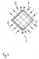
- FIG. 2 shows a schematic, perspective view of the in FIG. 1 shown plate heat exchanger 2 and a graphical illustration of the plate heat exchanger 2 by flowing air streams according to the embodiment.
- the plate heat exchanger 2 comprises three stacked, square metal plates, which in FIG. 2 are each shown standing on a corner.
- the lower and middle plates of the plate heat exchanger 2 have a slit-like hot air inlet 102 on the upper left side and a slit-like cold air outlet 103 on the lower right side.
- the lower plate On the left lower and on the right upper side, the lower plate is connected to the middle plate of the plate heat exchanger 2 each having a continuous wall.
- On the right upper side of the plate heat exchanger 2 there is a slot-like cold air inlet 104 between the middle and upper plates.
- a wall is provided between the middle and the upper plate.
- an exhaust air flow 12 flows into the warm air inlet 102, flows through the plate heat exchanger 2 and exits on the opposite side as exhaust air stream 13 from the cold air outlet 103.
- the case of the exhaust air flow 12 through the area of the plate heat exchanger 2 is also referred to as a cooling side.
- An outside air flow 14 enters the plate heat exchanger 2 through the cold air inlet 104, flows through it and exits the hot air outlet 105 as a supply air flow 15 on the opposite side.
- the area of the plate heat exchanger 2 through which the outside air flow 14 flows is also called the heating side of the plate heat exchanger 2.
- FIG. 3 shows a schematic representation of a cross section along the section line AA attached to an outer wall 17 air exchange device 1 according to the embodiment. In FIG. 3 is considered the heating side of the plate heat exchanger 2.
- the air exchange device 1 rests with the back of its housing 3 on the front of the outer wall 17 and is accordingly in the building interior. From the cross-sectional view in FIG. 3 It can be seen that the diagonal height of the air exchange system 1 corresponds approximately to three times its depth.
- the interior of the housing 3 is divided into a topmost arranged outside air inlet area, in a centrally located plate heat exchanger area and in a lowermost Zu Kunststoffauslenfin Kunststoffe.
- the outside air inlet opening 4 is formed on the rear side of the housing 3, to which a horizontal outside air supply pipe 18 connects on the outside wall side.
- the plate heat exchanger 2 is arranged, the three parallel, as shown in FIG FIG. 3 From top to bottom extending air ducts.
- the plate heat exchanger 2 shown here corresponds in principle to the plate heat exchanger 2 FIG. 2 , but has eight plates arranged one above the other.
- a supply air impeller 16 is disposed within the supply air fan housing 9.
- the supply air fan 16 is arranged horizontally in the middle.
- a Zuluftauslouö réelle 11 is provided in the front of the housing 3 and in the left side of the supply air fan housing 9, whose height corresponds to the width of the fan blades.
- the supply air fan housing starts at the left and at the right end of the underside of the plate heat exchanger 2, runs vertically downwards on both sides and has a horizontal underside directly in front of the underside of the housing 3.
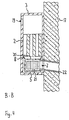
- FIG. 4 shows a schematic representation of a cross section along the section line BB of the attached to the outer wall 17 air exchange system 1 according to the embodiment.
- the cooling side of the plate heat exchanger 2 is considered.
- the interior of the housing 3 is divided into an upper exhaust air inlet area, a central plate heat exchanger area and a lower exhaust air outlet area.
- an exhaust air inlet opening 19 is provided on the front side of the housing 3.
- the plate heat exchanger region of the plate heat exchanger 2 is arranged, the four parallel, having vertically extending air ducts.
- the plate heat exchanger 2 shown here corresponds in principle to the plate heat exchanger 2 FIG. 2 , but has eight plates arranged one above the other.
- the exhaust air discharge area includes one in construction, in size and in alignment with the one in FIG FIG. 3 shown Zu Kunststofflwillerrad 16 identical Fortllibraryllibraryerrad 21.
- the exhaust air fan 21 is centered within the exhaust fan housing 5 is arranged.
- an exhaust air outlet opening 7 At this exhaust air outlet 7 is an exhaust air outlet pipe 22, which extends slightly inclined to the right below. Centered on the top of the exhaust air fan housing 5, an exhaust air supply opening 20 is provided whose width corresponds to approximately one third of the total width of the exhaust air fan housing 5. Between the left and the right end of the underside of the plate heat exchanger 2 and the left and right sides of the top of the exhaust air fan housing 5, the hopper 8 is arranged.
- the exhaust air fan 6 and the exhaust air fan 21 sucks by the movement of the fan blades 23 at the same time to warm exhaust air from the building interior.
- This exhaust air flow 12 flows into the air ducts of the plate heat exchanger 2.
- the exhaust air stream 12 is cooled.
- the exhaust air stream 12 then passes through the funnel 8 and through the exhaust air supply opening 20 in the exhaust air fan housing 5.
- FIG. 5 shows a schematic plan view of a building section 23 with three attached to the inside of the outer wall 17 of this building section 23 air exchange devices 28, 29 and 30 according to a first embodiment.
- the building section 23 has a rectangular oblong shape and is divided into a first space 24, a second space 25, a third space 26, and a fourth space 27.
- the first space 24 has a rectangular shape in the left quarter of the building section 23 and extends over the entire depth of the building section 23.
- the left, the front and the rear boundary of the first space 24 are formed by a portion of the outer wall 17.
- the first space 24 is delimited by a straight partition wall, in whose front area a first door 241 is arranged, which connects the first space 24 with the fourth space 27.
- the fourth space 27 has a width of a good third of the total width of the building section 23 and a depth of approximately one third of the total depth of the building section 23.
- a portion of the outer wall 17 forms the front end of the fourth space 27.
- Behind the fourth space 27 is the second space 25, which is separated from the fourth space 27 by a straight partition.
- a second door 251 is arranged, which connects the fourth space 27 with the second space 25.
- Right outside the second space 25 and right of the fourth space 27 is the third space 26. It extends over the entire depth and over a third of the total width of the building portion 23.
- the third space 26 is defined by a straight partition of the second space 25 and separated from the fourth space 27, wherein in the front
- a third door 261 for connecting the third space 26 is arranged with the fourth space 27 of this partition wall.
- an entrance door 271 is provided which leads into the fourth room 27.
- a first air exchange device 28 is located in a left region of the rear wall of the first space 24.
- a second air exchange device 29 is provided in a right region of the rear wall of the second space 25.
- a third air exchange device 30 is disposed in a right portion of the rear wall of the third space 26.
- the air exchange devices 28 to 30 are each mounted with their back of the housing 3 to the inside of the outer wall 17.
- behind the air exchange devices 28 to 30 each extend an outside air supply pipe 18 and an exhaust air outlet pipe 22.
- the outside air supply pipes 18 are shown in dashed lines in Figure 5 respectively.
- the air exchanging devices 28 to 30 are fixed to the outer wall 17 so that their outside air intake ports 4 abut respectively on the outside air supply pipe 18 and its exhaust air outlet port 7 on the exhaust air outlet pipe 22, respectively.
- the first air exchange device 28, the second air exchange device 29 and the third air exchange device 30 each promote a supply air flow 15 into the interior of the building section 23 and simultaneously promote a stream of exhaust air 13 from the interior of the building section 23 to the rear the building section 23 located outside of the building section 23rd
- the supply air fan 16 and the exhaust air fan 21 rotate at the same rotational frequency, so that the volume of the supply air 15 coincides with the volume of the exhaust air stream 13. With this mode of operation of the second air exchange device 29, a sufficient supply of the second space 25 is ensured with fresh heated outside air.
- the supply air impeller 16 of the first air exchange device 28 is operated at a 50% higher rotational frequency than the exhaust air impeller 21 of the first air exchange device 28.
- the funded by the first air exchange device 28 in the first space 24 supply air 15 is therefore greater by about 50% formed by the first air exchange device 28 more fresh supply air is conveyed into the first space 24, as spent exhaust air is conveyed out of it.
- the exhaust air impeller 21 of the third air exchange device 30 is operated at a rotational frequency that is 50% higher than the supply air impeller 16 of the third air exchange device 30. Accordingly, the volume of the exhaust air flow 13 conveyed out of the third space 26 is made larger by approximately 50% than that Volume of the supply air flow 15 conveyed from the outside of the building section 23 into the third space 26.
- the third air exchange device 28 thus conveys less fresh supply air into the third space 26, as spent exhaust air is transported out of him.
- FIG. 5 shown by arrows air movement between the first air exchange device 28 and the third air exchange device 30.
- the arrows that are in FIG. 5 between the second space 25 and the third space 26 do not pay attention.
- the result is an air flow which, starting from the first air exchange device 28, extends through the first space 24, through the fourth space 27 and through the third space 26 to the third air exchange device 30. This ensures that the first space 24 and the third space 26 and arranged between these two rooms fourth space 27 is supplied with fresh heated supply air.
- FIG. 5 a second variant of the second embodiment explained in which the first door 241, the second door 251 and the third door 261 are opened and the entrance door 271 are closed.
- both the first air exchange device 28 and the second air exchange device 29, the supply air impellers 16 each having a rotational frequency which is formed by about 25% higher than the rotational frequency of the exhaust air impellers 21. Accordingly, from the air exchange devices 28 and 29 respectively approximately 25% more supply air is conveyed into the interior of the building section 23, as outgoing air is conveyed out.
- the volume ratio of the supply air flow 15 to the exhaust air flow 13 in the case of the air exchange devices 28 and 29 is 55:45 in each case.
- the exhaust fan 21 of the third air exchange device 30 rotates at a rotational frequency which is greater by approximately 50%, than the rotational frequency of the supply air impeller 16 of the third air exchange device 30.
- the funded by the third air exchange device 30 in the third space 26 supply air 15 is therefore designed to be approximately 50% smaller than the simultaneously conveyed from the third space 26 to the outside of the building section 23 exhaust air stream 13.
- the ratio of the supply air flow 15 to the exhaust air stream 13 is approximately 40:60.
- This mode of operation of the air exchange devices 28-30 ensures supply of the rooms 24 to 27 with fresh, unused outside air.
- the fourth space 27 is vented, in which there is not directly an air exchange device.
- the air movement passes from the first air exchange device 28 through the first space 24, through the fourth space 27 and through the third space 26 to the third air exchange device 30 and from the second air exchange device 29 via the second space 25, over the fourth space 27 and over third space 26 to the third air exchange device 30.
- These air movements are in FIG. 5 represented by arrows.
- variants of the first embodiment can also larger building sections 23 with be ventilated the air exchange devices according to the invention.
- a far greater number of air exchange devices can be used, wherein an air exchange system with an even number of air exchange devices works very effectively.
- FIG. 6 shows a schematic sectional view of a residential building 31 with a chimney 32 and a chimney 33 and a schematic representation of an in this house 31 air exchange system according to a second embodiment.
- the chimney 32 and of this chimney 32 vertically upwardly leading chimney 33 are arranged in the left area of the building interior of the residential building 31. Through the chimney 32, the resulting in the combustion process in the chimney 32 gases can escape to an outside of the residential building 31.
- FIG. 6 shown air exchange system is divided into a fourth air exchange device 38, in a temperature sensor 34, in a ventilation flap 35 with a ventilation flap switch 36, in a differential pressure sensor 37, in a smoke detector 39, in an emergency ventilation device 40, in an alarm generator 41 and in a control unit 42nd
- the temperature sensor 34 is disposed in a lower portion of the chimney 33 and measures the temperature of the escaping gases.
- the controllable via a ventilation flap switch 36 ventilation flap 35 is in FIG. 6 located slightly above the temperature sensor 34.
- This ventilation flap 35 is rotatably formed and closes in a horizontal state, the inner cross section of the chimney 33 from tight, so that no Gases can escape more up. In the illustration in FIG. 6 the ventilation flap 35 is in a slightly oblique and thus open state.
- the corresponding in their construction of the air exchange device 1 fourth air exchange device 38 is mounted on the inside of the right outer wall 17 of the residential building 31.
- the smoke detector 39 is disposed in the interior of the fourth air exchange device 38 directly to the exhaust air inlet opening 19.
- the differential pressure sensor 37 is in FIG. 6 shown as a U-shaped tube with a liquid contained therein. The left half of this U-shaped tube is located within the house 31, the right half outside the house 31. The lower slightly bent connecting piece of the two areas passes through the outer wall 17.
- the two upper pipe ends of the differential pressure sensor 37 are open, so that the In the differential pressure sensor 37 filled liquid at different pressure ratios between the inside and the outside of the house 31 each on the inside and on the outside of the differential pressure sensor 37 has different heights of the water column.
- the in FIG. 6 Accordingly, in the building interior of the house 31 there is a relative negative pressure to the outside of the house 31. In practice, the heights of this column of water are either electronically by sensors or optically detected by cameras.
- the emergency ventilation device 40 is arranged on the left outer wall 17 of the residential building 31. Within this emergency ventilation device 40, an emergency air fan is provided, which sucks outside air through a provided in the outer wall 17 emergency air supply pipe and transported by a arranged in the emergency ventilation device 40 Notluftzuchtloch in the building interior of the residential building 31.
- control unit 42 has on its top four inputs and on its bottom three outputs.
- the four inputs of the control unit 42 are each connected by wire or cable connections to the temperature sensor 34, with the ventilation flap switch 36, with the differential pressure sensor 37 and the smoke detector 39.
- the outputs of the control unit 42 are also connected by wire or cable connections to the fourth air exchange device 38, with the emergency ventilation device 40 and with the alarm device 41.
- radio links can be provided in combination with transmitters and receivers.
- the control unit 42 has only one input and only one output.
- the input of the control unit 42 is connected to the ventilation flap switch 36 of the ventilation flap 35, the output of the control unit 42 is in communication with the fourth air exchange device 38.
- the ventilation flap switch 36 is in a closed state and the fourth air exchange device 38 is in a paused state.
- the combustion process in the chimney 32 is started by a user and the ventilation flap switch 36 is actuated, whereby the ventilation flap 35 is opened, so that the gases produced during the combustion process can escape upwards.
- the control unit 42 detects at its input the change in state of the ventilation flap switch 36 and outputs via its output a signal to the fourth air exchange device 38 from.
- the fourth air exchange device 38 then takes their operation, wherein the rotational frequency of the supply air fan 16 is formed higher than the rotational frequency of the exhaust air fan 21 to provide air circulation and to provide enough oxygen for the combustion process.
- the vent door 35 is set in a closed state by operation of the vent flap switch 36. This is done by the control unit 42, which then turns off the fourth air exchange device 38.
- a second input of the control unit 42 is additionally connected to the temperature sensor 34.
- This temperature sensor 34 sends signals to the control unit 42, if the temperature measured by it falls below a predetermined lower limit value or exceeds a likewise predetermined upper limit value. If the temperature measured by the temperature sensor 34 is below the lower limit value, the control unit 42 sends a signal to the fourth air exchange device 38, which causes it to increase the rotational frequency of the supply air fan 16 and / or the rotational frequency of the exhaust air To reduce fans 21. This increases the amount of oxygen supplied to the combustion process, causing heating.
- the control unit 42 sends a signal to the fourth air exchange device 38, which reduces the rotational frequency of the supply air fan 16 and / or increases the rotational frequency of the exhaust air fan 21 causes. As a result, the amount of oxygen to be supplied to the combustion process is reduced, which results in a reduction of the temperature. It is also conceivable that when the upper limit value is exceeded by the temperature value measured by the temperature sensor 34, the fourth air exchange device 38 is completely switched off.
- the third input of the control unit 42 is additionally connected to the differential pressure sensor 37.
- the pressure difference between the inside and the outside of the dwelling house 31 is zero.
- the combustion process is started in the chimney 32, whereby the gases produced during the combustion escape upwards.
- the ventilation flap switch 36 is actuated, whereby the ventilation flap 35 is opened.
- the differential pressure sensor 37 detects a pressure difference between the pressure of 5 Pa prevailing on the outside and on the inside. This is detected by the control unit 42, whereupon the fourth air exchange device 38 is put into operation, wherein the supply air fan 16 operates at a significantly higher rotational frequency than the exhaust air fan 21. This achieves a reduction of the detected pressure difference.
- the smoke detector 39 is additionally connected to the fourth input of the control unit 42. If it is determined by this smoke detector 39 that exist in the exhaust air flow 12 existing harmful gases, such as CO, CO 2 or Cl a predetermined maximum concentration, the rotational frequencies of the supply air fan 16 and the exhaust air fan 21 are further increased.
- the alarm transmitter 41 is additionally connected to the second output of the control unit 42.
- This alarm generator 41 can then be actuated by the control unit 42 when the temperature sensor 34 detects an excessive temperature and / or when the smoke detector 39 detects an increased concentration of noxious gases in the exhaust air flow and / or if the differential pressure sensor 37 either exceeding the limit of 10 Pa registered by the differential pressure ⁇ p or when a differential pressure of more than 5 Pa longer than a user definable period of time is applied.
- an emergency ventilation device 40 is connected to the third output of the control unit 42. This emergency ventilation device 40 is then switched on when the smoke detector 39 detects a certain concentration of noxious gas in the building interior of the dwelling house 31 and / or if the differential pressure ⁇ p is greater than a limit of 10 Pa or if the differential pressure is longer than a predetermined period of time above the threshold value of 5 Pa lies.
Landscapes
- Engineering & Computer Science (AREA)
- Chemical & Material Sciences (AREA)
- Combustion & Propulsion (AREA)
- Mechanical Engineering (AREA)
- General Engineering & Computer Science (AREA)
- Physics & Mathematics (AREA)
- Fluid Mechanics (AREA)
- Ventilation (AREA)
- Building Environments (AREA)
- Central Air Conditioning (AREA)
Abstract
Description
Die Erfindung betrifft ein Luftaustauschsystem für die Belüftung wenigstens eines Raums eines Gebäudes mit wenigstens einer Luftaustauschvorrichtung.The invention relates to an air exchange system for the ventilation of at least one room of a building with at least one air exchange device.
Zur Gewährleistung gleichbleibend hoher Atemluftqualität in Wohn- und Arbeitsräumen von Gebäuden wird oft ein Luftaustausch mit der Umwelt erzwungen. Dabei wird kühlere, unverbrauchte Außenluft in das Gebäudeinnere gefördert und gleichzeitig wärmere, verbrauchte Abluft aus dem Gebäudeinneren nach draußen gefördert. Aus Energieeffizienzgründen kann die Wärmeenergie der Abluft dazu verwendet werden, um die hineinströmende Außenluft zu erwärmen.To ensure consistently high quality of breathing air in living and working spaces of buildings, air exchange with the environment is often forced. In doing so, cooler, unconsumed outside air is conveyed into the interior of the building and, at the same time, warmer, exhausted exhaust air is conveyed out of the interior of the building. For energy efficiency reasons, the heat energy of the exhaust air can be used to heat the incoming outside air.
Dabei kommen Wärmetauscher zum Einsatz, die Wärme in Richtung eines Temperaturgefälles zwischen den zwei Luftströmen übertragen. Es sind Rohrbündel-, Rippenrohr-, Platten-, Spiral-, Spiralrohr-Doppelmantel- und Wickelwärmetauscher bekannt. Solche Wärmetauscher sind häufig Bestandteile von Luftaustauschvorrichtungen, die auch als Rekuperatoren oder als Rekuperativgeräte bezeichnet werden.In this case, heat exchangers are used, which transfer heat in the direction of a temperature gradient between the two air streams. There are known tube bundle, finned tube, plate, spiral, spiral tube double-jacket and coil heat exchanger. Such heat exchangers are often components of air exchange devices, which are also referred to as recuperators or as recuperative devices.
Bei Gebäudeabschnitten mit mehreren Räumen, bei denen ein Luftaustausch mittels einer dezentralen Luftaustauschvorrichtung mit einem Wärmetauscher vorgenommen wird, ergibt sich oft das Problem, daß dieser Luftaustausch nicht zufriedenstellend ist. Besonders diejenigen Räume, in denen sich die Luftaustauschvorrichtung nicht unmittelbar befindet, werden häufig nur unzureichend mit frischer und unverbrauchter Luft versorgt.In building sections with several rooms, in which an air exchange is performed by means of a decentralized air exchange device with a heat exchanger, often results in the problem that this air exchange is not satisfactory. Especially those rooms in which the air exchange device is not immediately become common insufficiently supplied with fresh and unused air.
Es ist daher Aufgabe der Erfindung, ein einfach handzuhabendes Luftaustauschsystem mit gutem Wirkungsgrad anzugeben, bei dem in allen zu belüftenden Räumen ein ausreichender Luftaustausch stattfindet.It is therefore an object of the invention to provide an easy-to-handle air exchange system with good efficiency, in which there is a sufficient exchange of air in all rooms to be ventilated.
Diese Aufgabe wird durch den Gegenstand des unabhängigen Anspruchs gelöst. Vorteilhafte Ausgestaltungen ergeben sich aus den Unteransprüchen.This object is solved by the subject matter of the independent claim. Advantageous embodiments emerge from the subclaims.
Aus der
Aus der
Ein weiteres Luftaustauschsystem ist aus
Gemäß einem Grundgedanken der Erfindung sorgt jede in dem Luftaustauschsystem vorgesehene Luftaustauschvorrichtung bereits für sich allein genommen für einen Abtransport von verbrauchter Fortluft sowie für ein Einströmen von frischer Zuluft. Gemäß einem weiteren Grundgedanken der Erfindung entsteht eine Luftbewegung zwischen derjenigen Luftaustauschvorrichtung, die lediglich einen Zuluft-Lüfter aufweist und derjenigen Luftaustauschvorrichtung, die lediglich einen Fortluft-Lüfter umfaßt. Diese Luftbewegung ist von der Luftaustauschvorrichtung mit dem Zuluft-Lüfter zu der Luftaustauschvorrichtung mit dem Fortluft-Lüfter gerichtet. Durch diese Luftbewegung wird sichergestellt, daß auch Bereiche, die nicht in unmittelbarer Nähe der Luftaustauschvorrichtungen liegen, mit frischer Außenluft versorgt werden.In accordance with one aspect of the invention, each air exchange device provided in the air exchange system already provides taken for itself for a removal of spent exhaust air and for an influx of fresh supply air. According to a further basic concept of the invention, an air movement is created between that air exchange device which has only one supply air fan and the one air exchange device which only comprises one exhaust air fan. This air movement is directed from the air exchange device with the supply air fan to the air exchange device with the exhaust air fan. This air movement ensures that even areas that are not in the immediate vicinity of the air exchange devices are supplied with fresh outdoor air.
Durch ein derartiges Luftaustauschsystem wird ein zufriedenstellender Luftaustausch mit einem guten Wirkungsgrad erreicht.By such an air exchange system, a satisfactory exchange of air is achieved with good efficiency.
Ein weiterer Grundgedanke der Erfindung besteht darin, daß bei wenigstens einer Luftaustauschvorrichtung der Zuluft-Lüfter und der Fortluft-Lüfter so ein-stellbar sind, daß der Zuluftstrom größer als der Fortluftstrom ausgebildet ist und daß bei wenigstens einer weiteren Luftaustauschvorrichtung der Zuluft-Lüfter und der Fortluft-Lüfter so einstellbar sind, daß der Fortluftstrom größer als der Zuluftstrom ausgebildet ist. Durch eine derartige Einstellbarkeit der Volumenströme der durch den Zuluft-Lüfter und durch den Fortluft-Lüfter geförderten Luftmengen kann der Luftaustausch der einzelnen Luftaustauschvorrichtungen und somit der Luftaustausch des Luftaustauschsystems individuell an die Umgebung angepaßt werden. Zusätzlich zu demjenigen Luftaustausch, den jede Luftaustauschvorrichtung für sich allein gesehen tätigt, wird eine Luftbewegung zwischen den einzelnen Luftaustauschvorrichtungen erzeugt. Dadurch wird ein Luftaustausch auch in denjenigen Bereichen sichergestellt, die sich nicht in unmittelbarer Umgebung einer der Luftaustauschvorrichtungen befinden.Another basic idea of the invention is that in at least one air exchange device of the supply air fan and exhaust air fan are so adjustable that the supply air is greater than the exhaust air flow and that in at least one other air exchange device of the supply air fan and the Exhaust air fans are adjustable so that the exhaust air flow is greater than the supply air flow is formed. Such an adjustability of the volume flows of the air volumes supplied by the supply air fan and by the exhaust air fan allows the air exchange of the individual air exchange devices and thus the air exchange of the air exchange system to be adapted individually to the environment. In addition to the air exchange that each air exchange device makes on its own, air movement is created between the individual air exchange devices. As a result, an air exchange is ensured even in those areas that are not in the immediate vicinity of one of the air exchange devices.
Die Intensität der Luftbewegung zwischen den einzelnen Luftaustauschvorrichtungen kann durch eine Veränderung der Drehfrequenzen der Lüfter und/oder der Anstellwinkel der Lüfterblätter genau und bedarfsgerecht eingestellt werden.The intensity of the air movement between the individual air exchange devices can be adjusted accurately and as needed by changing the rotational frequencies of the fans and / or the angle of attack of the fan blades.
Bei einer einfachen Version des erfindungsgemäßen Luftaustauschsystems, die zwei Luftaustauschvorrichtungen umfaßt, kann die erste Luftaustauschvorrichtung beispielsweise mit einem Verhältnis des Fortluftstromvolumens zum Zuluftstromvolumen von 40%/60% und die zweite Luftaustauschvorrichtung beispielsweise mit einem Verhältnis des Fortluftstromvolumens zum Zuluftstromvolumen von 60%/40% betrieben werden. Eine Richtungsänderung der Luftbewegung zwischen den Luftaustauschvorrichtungen kann dadurch erreicht werden, indem das Verhältnis des Fortluftstromvolumens zu dem Zuluftstromvolumen bei beiden Luftaustauschvorrichtungen umgekehrt wird.In a simple version of the air exchange system according to the invention comprising two air exchange devices, the first air exchange device may operate, for example, with a ratio of the exhaust air flow volume to the supply air flow volume of 40% / 60% and the second air exchange device with a ratio of the exhaust air flow volume to the supply air flow volume of 60% / 40% become. A change of direction The air movement between the air exchange devices can be achieved by reversing the ratio of the exhaust air flow volume to the supply air flow volume in both air exchange devices.
Von der Erfindung sind auch Luftaustauschsysteme umfaßt, die drei oder mehr Luftaustauschvorrichtungen aufweisen. Solche Luftaustauschsysteme werden auch als Netzwerkversionen bezeichnet.The invention also includes air exchange systems having three or more air exchange devices. Such air exchange systems are also referred to as network versions.
Die Erfindung betrifft auch ein vorstehend beschriebenes Luftaustauschsystem mit wenigstens einer Außenwand des Gebäudes. Dabei sind die Gehäuserückseiten der Luftaustauschvorrichtungen an wenigstens einer Außenwand des Gebäudes angebracht. An bzw. in der Außenwand sind Rohrverbindungen vorgesehen, die sich bis zu der Außenseite des Gebäudes erstrecken. Über diese Rohrverbindungen kann frische unverbrauchte Außenluft in die Luftaustauschvorrichtungen hinein und verbrauchte Fortluft aus den Luftaustauschvorrichtungen auf die Außenseite des Gebäudes gelangen. Mit derart angebrachten Luftaustauschvorrichtungen wird ein direkter und effektiver Luftaustausch der verbrauchten Abluft mit frischer Außenluft erreicht.The invention also relates to an above-described air exchange system having at least one outer wall of the building. In this case, the rear sides of the air exchange devices are attached to at least one outer wall of the building. On or in the outer wall pipe connections are provided, which extend to the outside of the building. Fresh unused external air into the air exchange devices and spent exhaust air from the air exchange devices can reach the outside of the building via these pipe connections. With such mounted air exchange devices, a direct and effective air exchange of the spent exhaust air is achieved with fresh outdoor air.
Gemäß einer ersten Ausführungsform der Erfindung ist wenigstens eine Luftaustauschvorrichtung an einer ersten Außenwand und wenigstens eine weitere Luftaustauschvorrichtung an einer zweiten Außenwand angebracht. Wenn diese beiden Wände einander gegenüberliegen, so wird der zwischen den beiden Wänden liegende Gebäudeabschnitt kontinuierlich mit frischer und erwärmter Zuluft versorgt.According to a first embodiment of the invention, at least one air exchange device is attached to a first outer wall and at least one further air exchange device is attached to a second outer wall. When these two walls face each other, the building section lying between the two walls is continuously supplied with fresh and heated supply air.
Befinden sich die erste Außenwand sowie die zweite Außenwand in unterschiedlichen Räumen des Gebäudes, so werden die zwischen den beiden Außenwänden liegenden Räume des Gebäudes ebenfalls kontinuierlich mit frischer erwärmter Außenluft durchspült. Hierbei ist sicherzustellen, daß die Luftbewegung zwischen diesen Räumen nicht beispielsweise durch eine geschlossene Tür unterbrochen wird.If the first outer wall and the second outer wall are located in different rooms of the building, the rooms between the two outer walls of the building are also continuously flushed with fresh, heated outside air. It must be ensured that the air movement between these rooms is not interrupted, for example, by a closed door.
Wenn zwischen der ersten Außenwand und der zweiten Außenwand wenigstens ein Durchgang, insbesondere eine Treppe, eine Tür oder ein Korridor und/oder wenigstens ein weiterer Raum angeordnet ist, so werden diese ebenfalls kontinuierlich mit frischer erwärmter Außenluft versorgt. Dies wird auch als Querlüftung bezeichnet.If at least one passage, in particular a staircase, a door or a corridor and / or at least one further space is arranged between the first outer wall and the second outer wall, these are likewise continuously supplied with fresh, heated outside air. This is also called cross ventilation.
Gemäß der Erfindung sind die Luftaustauschvorrichtungen mit einer Steuerungseinheit, insbesondere mit einem Computer, verbunden. Über diese Steuerungseinheit können die Drehfrequenzen der Lüfterräder und/oder die Anstellwinkel der Lüfterblätter für die Zuluft-Lüfter und für die Fortluft-Lüfter der einzelnen Luftaustauschvorrichtungen individuell und präzise eingestellt werden.According to the invention, the air exchange devices are connected to a control unit, in particular to a computer. About this control unit, the rotational frequencies of the fan wheels and / or the angle of attack of the fan blades for the supply air fan and exhaust air fan of the individual air exchange devices can be set individually and precisely.
Die Erfindung ist in den Zeichnungen anhand eines Ausführungsbeispiels näher veranschaulicht.
- Figur 1
- zeigt eine schematische Darstellung einer Draufsicht auf eine Luftaustauschvorrichtung gemäß einem Ausführungsbeispiel,
Figur 2- zeigt eine schematische, perspektivische Darstellung des in
Figur 1 gezeigten Plattenwärmetauschers sowie eine grafische Veranschaulichung der den Plattenwärmetauscher durchfließenden Luftströme gemäß dem Ausführungsbeispiel, Figur 3- zeigt eine schematische Darstellung eines Querschnitts entlang der Schnittlinie A-A einer an einer Außenwand befestigten Luftaustauschvorrichtung gemäß dem Ausführungsbeispiel,
Figur 4- zeigt eine schematische Darstellung eines Querschnitts entlang der Schnittlinie B-B der an der Außenwand befestigten Luftaustauschvorrichtung gemäß dem Ausführungsbeispiel,
Figur 5- zeigt einen schematischen Grundriß eines Gebäudeabschnitts mit drei an der Innenseite einer Außenwand dieses Gebäudeabschnitts befestigten in
Figur 1 gezeigten Luftaustauschvorrichtungen gemäß einem ersten Ausführungsbeispiel, - Figur 6
- zeigt eine schematische Schnittdarstellung eines Wohnhauses mit einem Kamin und mit einem Schornstein sowie eine schematische Darstellung eines in diesem Wohnhaus befindlichen Luftaustauschsystems gemäß einem zweiten Ausführungsbeispiel.
- FIG. 1
- shows a schematic representation of a plan view of an air exchange device according to an embodiment,
- FIG. 2
- shows a schematic, perspective view of the in
FIG. 1 shown plate heat exchanger and a graphical illustration of the plate heat exchanger flowing through air streams according to the embodiment, - FIG. 3
- shows a schematic representation of a cross section along the section line AA attached to an outer wall air exchange device according to the embodiment,
- FIG. 4
- shows a schematic representation of a cross section along the section line BB of the attached to the outer wall air exchange device according to the embodiment,
- FIG. 5
- shows a schematic plan view of a building section with three attached to the inside of an outer wall of this building section in
FIG. 1 shown air exchange devices according to a first embodiment, - FIG. 6
- shows a schematic sectional view of a residential building with a chimney and a chimney and a schematic representation of a located in this house air exchange system according to a second embodiment.
Die Luftaustauschvorrichtung 1 ist von einem quadratischen Gehäuse 3 umschlossen. Bei der in
Mittig in dem Gehäuse 3 ist ein quadratischer Plattenwärmetauscher 2 angeordnet, insbesondere aus gut wärmeleitendem Metall, wobei in der Draufsicht gemäß
Oberhalb der rechten oberen Seite des Plattenwärmetauschers 2 ist eine kreisrunde Außenlufteinlaßöffnung 4 in der Unterseite des Gehäuses 3 vorgesehen. Um die Außenlufteinlaßöffnung 4 ist eine auf der Unterseite des Gehäuses 3 aufsetzende, gekrümmte Wand vorgesehen, die am oberen sowie am unteren Ende der rechten oberen Seite des Plattenwärmetauschers 2 abschließt.Above the right upper side of the
Auf der linken oberen Seite des Plattenwärmetauschers 2 ist eine ähnlich geformte Wand vorgesehen, die am oberen sowie am unteren Ende der linken oberen Seite des Plattenwärmetauschers 2 abschließt. In der hier nicht gezeigten Vorderseite des Gehäuses 3 ist eine Öffnung vorgesehen, die beim Aufsetzen der Vorderseite auf das Gehäuse 3 innerhalb dieser Wand angeordnet ist.On the left upper side of the
An der rechten unteren Seite des Plattenwärmetauschers 2 ist ein Fortluft-Lüftergehäuse 5 mit einem Fortluftradiallüfter 6 sowie ein zwischen dem Fortluftradiallüfter 6 und dem Plattenwärmetauscher 2 angeordneter Trichter 8 vorgesehen. Der Trichter 8 setzt auf der gesamten Breite der rechten unteren Seite des Plattenwärmetauschers 2 an und verjüngt sich auf einer Strecke etwa einem Achtel der Seitenlänge des Plattenwärmetauschers 2 um einen Winkel von 30°. Auf der gesamten Breite des Auslaßseite des Trichters 8 setzt der Fortluftradiallüfter 6 an, von dem in der Draufsicht in
An der linken unteren Seite des Plattenwärmetauschers 2 setzt ein von einem dünnwandigen Zuluft-Lüftergehäuse 9 umschlossener Zuluftansaugradiallüfter 10 an. Dabei ist die Drehachse des Zuluftansaugradiallüfters 10 orthogonal zu der linken unteren Seite des Plattenwärmetauschers 2 auf der Höhe deren Mitte angeordnet. Der Durchmesser bzw. die Breite des Zulaufansaugradiallüfters 10 entspricht in etwa der Seitenlänge des Plattenwärmetauschers 2, seine Tiefe entspricht ungefähr der Hälfte seiner Breite. In dem linken oberen Bereich des Zuluftansaugradiallüfters 10 ist eine rechteckige Zulufteinlaßöffnung angeordnet, durch die mehrere Lüfterschaufeln des Zuluftansaugradiallüfters 10 erkennbar sind. Diese sind im Ausführungsbeispiel parallel zur Drehachse des Zuluftansaugradiallüfters 10 angeordnet, können jedoch auch schräg zu dieser oder gekrümmt verlaufen.On the left lower side of the
Ein erste Schnittlinie A-A verläuft durch die linke untere sowie durch die rechte obere Ecke des Gehäuses 3. Eine weitere Schnittlinie B-B verläuft durch die linke obere sowie durch die rechte untere Ecke des Gehäuses 3.A first cut line A-A passes through the lower left and right upper corners of the
Der Plattenwärmetauscher 2 umfaßt drei übereinander angeordnete, quadratische Metallplatten, die in
Gemäß der Darstellung in
Die Luftaustauschvorrichtung 1 liegt mit der Rückseite ihres Gehäuses 3 an der Vorderseite der Außenwand 17 an und befindet sich dementsprechend im Gebäudeinneren. Aus der Querschnittsdarstellung in
In dem Außenlufteinlaßbereich ist an der Rückseite des Gehäuses 3 die Außenlufteinlaßöffnung 4 ausgebildet, an die sich außenwandseitig ein waagerechtes Außenluftzufuhrrohr 18 anschließt. In dem Plattenwärmetauscherbereich ist der Plattenwärmetauscher 2 angeordnet, der drei parallele, in der Darstellung gemäß
Das Zuluft-Lüftergehäuse setzt auf dem linken sowie auf dem rechten Ende der Unterseite des Plattenwärmetauschers 2 an, verläuft beidseitig vertikal nach unten und weist unmittelbar vor der Unterseite des Gehäuses 3 eine waagerechte Unterseite auf.The supply air fan housing starts at the left and at the right end of the underside of the
Das Innere des Gehäuses 3 gliedert sich dabei in einen oberen Ablufteinlaßbereich, in einen mittleren Plattenwärmetauscherbereich und in einen unteren Fortluftauslaßbereich. Im Ablufteinlaßbereich ist auf der Vorderseite des Gehäuses 3 eine Ablufteinlaßöffnung 19 vorgesehen. Im Plattenwärmetauscherbereich ist der Plattenwärmetauscher 2 angeordnet, der vier parallele, vertikal verlaufende Luftführungen aufweist. Der hier gezeigte Plattenwärmetauscher 2 entspricht prinzipiell dem Plattenwärmetauscher 2 aus
Im folgenden wird die Funktionsweise der Luftaustauschvorrichtung 1 näher erläutert.In the following the operation of the air exchange device 1 will be explained in more detail.
Wie in
Wie in
Wie in
Der Gebäudeabschnitt 23 weist eine rechteckige längliche Form auf und gliedert sich in einen ersten Raum 24, in einen zwei-ten Raum 25, in einen dritten Raum 26 sowie in einen vierten Raum 27. Der erste Raum 24 weist eine rechteckige Form auf, befindet sich in dem linken Viertel des Gebäudeabschnitts 23 und erstreckt sich über die gesamte Tiefe des Gebäudeabschnitts 23. Die linke, die vordere und die hintere Begrenzung des ersten Raums 24 werden von einem Abschnitt der Außenwand 17 gebildet. Auf der rechten Seite wird der erste Raum 24 von einer gerade verlaufenden Zwischenwand begrenzt, in deren vorderem Bereich eine erste Tür 241 angeordnet ist, die den ersten Raum 24 mit dem vierten Raum 27 verbindet. Der vierte Raum 27 weist eine Breite von einem guten Drittel der Gesamtbreite des Gebäudeabschnitts 23 und eine Tiefe von ungefähr einem Drittel der Gesamttiefe des Gebäudeabschnitts 23 auf. Ein Abschnitt der Außenwand 17 bildet das vordere Ende des vierten Raums 27. Hinter dem vierten Raum 27 befindet sich der zweite Raum 25, der von dem vierten Raum 27 durch eine gerade verlaufende Zwischenwand getrennt ist. In dem rechten Bereich dieser Zwischenwand ist eine zweite Tür 251 angeordnet, die den vierten Raum 27 mit dem zweiten Raum 25 verbindet. Rechterhalb des zweiten Raums 25 und rechterhalb des vierten Raums 27 befindet sich der dritte Raum 26. Dieser erstreckt sich über die gesamte Tiefe und über ein gutes Drittel der Gesamtbreite des Gebäudeabschnitts 23. Der dritte Raum 26 ist durch eine gerade verlaufende Zwischenwand von dem zweiten Raum 25 und von dem vierten Raum 27 getrennt, wobei in dem vorderenThe
Bereich dieser Zwischenwand eine dritte Tür 261 zur Verbindung des dritten Raums 26 mit dem vierten Raum 27 angeordnet ist. An der Vorderseite des Gebäudeabschnitts 23 ist eine Eingangstür 271 vorgesehen, die in den vierten Raum 27 führt.A
Eine erste Luftaustauschvorrichtung 28 befindet sich in einem linken Bereich der hinteren Wand des ersten Raums 24. Eine zweite Luftaustauschvorrichtung 29 ist in einem rechten Bereich der hinteren Wand des zweiten Raums 25 vorgesehen. Eine dritte Luftaustauschvorrichtung 30 ist in einem rechten Bereich der hinteren Wand des dritten Raums 26 angeordnet. Die Luftaustauschvorrichtungen 28 bis 30 sind jeweils mit ihrer Rückseite des Gehäuses 3 an die Innenseite der Außenwand 17 montiert. Dabei verlaufen hinter den Luftaustauschvorrichtungen 28 bis 30 jeweils ein Außenluftzufuhrrohr 18 sowie ein Fortluftauslaßrohr 22. Die Außenluftzufuhrrohre 18 sind in Figur 5 jeweils gestrichelt dargestellt. Die Luftaustauschvorrichtungen 28 bis 30 sind so an der Außenwand 17 befestigt, daß ihre Außenlufteinlaßöffnung 4 jeweils auf dem Außenluftzufuhrrohr 18 und ihre Fortluftauslaßöffnung 7 jeweils auf dem Fortluftauslaßrohr 22 anliegen.A first
Nachfolgend wird mit Bezug auf
Die erste Luftaustauschvorrichtung 28, die zweite Luftaustauschvorrichtung 29 sowie die dritte Luftaustauschvorrichtung 30 fördern jeweils einen Zuluftstrom 15 in das Innere des Gebäudeabschnitts 23 und fördern gleichzeitig einen Fortluftstrom 13 aus dem Inneren des Gebäudeabschnitts 23 auf die hinter dem Gebäudeabschnitt 23 gelegene Außenseite des Gebäudeabschnitts 23.The first
Bei der zweiten Luftaustauschvorrichtung 29 drehen sich das Zuluft-Lüfterrad 16 und das Fortluft-Lüfterrad 21 mit derselben Drehfrequenz, so daß das Volumen des Zuluftstroms 15 mit dem Volumen des Fortluftstroms 13 übereinstimmt. Mit diesem Betriebsmodus der zweiten Luftaustauschvorrichtung 29 wird eine ausreichende Versorgung des zweiten Raums 25 mit frischer erwärmter Außenluft sichergestellt.In the second
Das Zuluft-Lüfterrad 16 der ersten Luftaustauschvorrichtung 28 wird mit einer um 50% höheren Drehfrequenz betrieben als das Fortluft-Lüfterrad 21 der ersten Luftaustauschvorrichtung 28. Der durch die erste Luftaustauschvorrichtung 28 in den ersten Raum 24 geförderte Zuluftstrom 15 ist demnach um ungefähr 50% größer ausgebildet als der aus dem ersten Raum 24 auf die Außenseite des Gebäudeabschnitts 23 geförderte Fortluftstrom 13. Durch die erste Luftaustauschvorrichtung 28 wird demnach mehr frische Zuluft in den ersten Raum 24 befördert, als verbrauchte Fortluft aus ihm hinausbefördert wird.The
Das Fortluft-Lüfterrad 21 der dritten Luftaustauschvorrichtung 30 wird mit einer um 50% höheren Drehfrequenz betrieben als das Zuluft-Lüfterrad 16 der dritten Luftaustauschvorrichtung 30. Dementsprechend ist das Volumen des aus dem dritten Raum 26 herausbeförderten Fortluftstroms 13 um ungefähr 50% größer ausgebildet als das Volumen des von der Außenseite des Gebäudeabschnitts 23 in den dritten Raum 26 hineinbeförderten Zuluftstroms 15. Durch die dritte Luftaustauschvorrichtung 28 wird somit weniger frische Zuluft in den dritten Raum 26 befördert, als verbrauchte Fortluft aus ihm hinausbefördert wird.The
In dem Gebäudeabschnitt 23 entwickelt sich eine in
Im folgenden wird mit Bezug auf
Dabei arbeiten sowohl bei der ersten Luftaustauschvorrichtung 28 sowie bei der zweiten Luftaustauschvorrichtung 29 die Zuluft-Lüfterräder 16 jeweils mit einer Drehfrequenz, die um ungefähr 25% höher ausgebildet ist als die Drehfrequenz der Fortluft-Lüfterräder 21. Dementsprechend wird von den Luftaustauschvorrichtungen 28 und 29 jeweils ungefähr 25% mehr Zuluft in das Innere des Gebäudeabschnitts 23 befördert, als Abluft hinausbefördert wird. Das Volumenverhältnis des Zuluftstroms 15 zu dem Fortluftstrom 13 beträgt bei den Luftaustauschvorrichtungen 28 und 29 jeweils 55:45.In this case, both the first
Das Fortluft-Lüfterrad 21 der dritten Luftaustauschvorrichtung 30 dreht sich mit einer Drehfrequenz, die um ca. 50% größer ist, als die Drehfrequenz des Zuluft-Lüfterrads 16 der dritten Luftaustauschvorrichtung 30. Der von der dritten Luftaustauschvorrichtung 30 in den dritten Raum 26 geförderte Zuluftstrom 15 ist daher um ca. 50% geringer ausgebildet als der gleichzeitig aus dem dritten Raum 26 auf die Außenseite des Gebäudeabschnitts 23 beförderte Fortluftstrom 13. Das Verhältnis des Zuluftstroms 15 zu dem Fortluftstrom 13 beträgt ungefähr 40:60.The
Durch diesen Betriebsmodus der Luftaustauschvorrichtungen 28-30 wird eine Versorgung der Räume 24 bis 27 mit frischer unverbrauchter Außenluft gewährleistet. Dabei wird auch der vierte Raum 27 durchlüftet, in dem sich nicht unmittelbar eine Luftaustauschvorrichtung befindet. Die Luftbewegung verläuft von der ersten Luftaustauschvorrichtung 28 durch den ersten Raum 24, durch den vierten Raum 27 und durch den dritten Raum 26 zu der dritten Luftaustauschvorrichtung 30 sowie von der zweiten Luftaustauschvorrichtung 29 über den zweiten Raum 25, über den vierten Raum 27 und über den dritten Raum 26 zu der dritten Luftaustauschvorrichtung 30. Diese Luftbewegungen sind in
Diese Luftbewegungen können sehr einfach modifiziert werden, indem die Drehfrequenzen der Zuluft-Lüfterräder 16 sowie der Fortluft-Lüfterräder 21 der Luftaustauschvorrichtungen 28-30 verändert werden.These air movements can be easily modified by the rotational frequencies of the
In weiteren, hier nicht gezeigten Varianten des ersten Ausführungsbeispiels können auch größere Gebäudeabschnitte 23 mit den erfindungsgemäßen Luftaustauschvorrichtungen belüftet werden. Dabei kann auch eine weit größere Zahl von Luftaustauschvorrichtungen zum Einsatz kommen, wobei ein Luftaustauschsystem mit einer geraden Anzahl von Luftaustauschvorrichtungen besonders effektiv arbeitet.In other, not shown variants of the first embodiment can also
Der Kamin 32 sowie der von diesem Kamin 32 senkrecht nach oben führende Schornstein 33 sind im linken Bereich des Gebäudeinneren des Wohnhauses 31 angeordnet. Durch den Kamin 32 können die bei dem Verbrennungsprozeß in dem Kamin 32 entstandenen Gase auf eine Außenseite des Wohnhauses 31 entweichen.The
Das in
Der Temperatursensor 34 ist in einem unteren Bereich des Schornsteins 33 angeordnet und mißt die Temperatur der entweichenden Gase. Die über einen Belüftungsklappenschalter 36 steuerbare Belüftungsklappe 35 ist in
Die in ihrem Aufbau der Luftaustauschvorrichtung 1 entsprechende vierte Luftaustauschvorrichtung 38 ist an die Innenseite der rechten Außenwand 17 des Wohnhauses 31 montiert. Der Rauchmelder 39 ist im Inneren der vierten Luftaustauschvorrichtung 38 unmittelbar an der Ablufteinlaßöffnung 19 angeordnet. Etwas oberhalb der vierten Luftaustauschvorrichtung 38 befindet sich der Differenzdrucksensor 37, der zur Messung der Druckdifferenz zwischen der Innenseite und der Außenseite des Wohnhauses 31 vorgesehen ist. Dieser Differenzdrucksensor 37 ist in
Etwas unterhalb der vierten Luftaustauschvorrichtung 38 befindet sich der akustische Alarmgeber 41, der zur Ausgabe von akustischen Signalen bzw. Signalfolgen fähig ist. Das Notlüftungsgerät 40 ist an der linken Außenwand 17 des Wohnhauses 31 angeordnet. Innerhalb dieses Notlüftungsgeräts 40 ist ein Notluft-Lüfter vorgesehen, der Außenluft durch ein in der Außenwand 17 vorgesehenes Notluftzufuhrrohr ansaugt und durch ein in dem Notlüftungsgerät 40 angeordnetes Notluftzufuhrloch in das Gebäudeinnere des Wohnhauses 31 befördert.Somewhat below the fourth
Die in einem mittleren Bereich des Wohnhauses 31 angeordnete Steuerungseinheit 42 weist auf ihrer Oberseite vier Eingänge und auf ihrer Unterseite drei Ausgänge auf. Die vier Eingänge der Steuerungseinheit 42 sind jeweils mittels Draht- bzw. Kabelverbindungen mit dem Temperatursensor 34, mit dem Belüftungsklappenschalter 36, mit dem Differenzdrucksensor 37 sowie mit dem Rauchmelder 39 verbunden. Die Ausgänge der Steuerungseinheit 42 sind ebenfalls mittels Draht- bzw. Kabelverbindungen mit der vierten Luftaustauschvorrichtung 38, mit dem Notlüftungsgerät 40 sowie mit dem Alarmgeber 41 verbunden. Anstelle der Kabel- bzw. Drahtverbindungen der Ein- und Ausgänge der Steuerungseinheit 42 können auch Funkverbindungen in Kombination mit Sendern und Empfängern vorgesehen sein.The arranged in a central region of the
Im folgenden wird die Funktionsweise der vierten Luftaustauschvorrichtung 38 in Verbindung mit der Steuerungseinheit 42, mit dem Temperatursensor 34, mit dem Belüftungsklappenschalter 36, mit dem Differenzdrucksensor 37, mit dem Rauchmelder 39, mit dem Notlüftungsgerät 40 und mit dem Alarmgeber 41 näher erläutert.In the following, the operation of the fourth
In einer ersten Variante des zweiten Ausführungsbeispiels weist die Steuerungseinheit 42 nur einen Eingang sowie nur einen Ausgang auf. Der Eingang der Steuerungseinheit 42 ist mit dem Belüftungsklappenschalter 36 der Belüftungsklappe 35 verbunden, der Ausgang der Steuerungseinheit 42 steht mit der vierten Luftaustauschvorrichtung 38 in Verbindung. Zu Beginn der ersten Variante des zweiten Ausführungsbeispiels befinden sich der Belüftungsklappenschalter 36 in einem geschlossenen Zustand und die vierte Luftaustauschvorrichtung 38 in einem Pausezustand. Nun wird von einem Benutzer der Verbrennungsprozeß in dem Kamin 32 gestartet und der Belüftungsklappenschalter 36 betätigt, wodurch die Belüftungsklappe 35 geöffnet wird, so daß die bei dem Verbrennungsprozeß entstehenden Gase nach oben entweichen können. Die Steuerungseinheit 42 erfaßt an ihrem Eingang die Zustandsänderung des Belüftungsklappenschalters 36 und gibt über ihren Ausgang ein Signal an die vierte Luftaustauschvorrichtung 38 ab. Die vierte Luftaustauschvorrichtung 38 nimmt daraufhin ihren Betrieb auf, wobei die Drehfrequenz des Zuluft-Lüfters 16 höher ausgebildet ist als die Drehfrequenz des Fortluft-Lüfters 21, um für eine Luftzirkulation zu sorgen und um genügend Sauerstoff für den Verbrennungsprozeß zur Verfügung zu stellen. Bei Beendigung des Verbrennungsprozesses wird die Belüftungsklappe 35 durch Betätigung des Belüftungsklappenschalters 36 in einen geschlosenen Zustand versetzt. Dies wird durch die Steuerungseinheit 42 erfaßt, die daraufhin die vierte Luftaustauschvorrichtung 38 abschaltet.In a first variant of the second exemplary embodiment, the
In einer zweiten Variante dieses Ausführungsbeispiels ist zusätzlich ein zweiter Eingang der Steuerungseinheit 42 mit dem Temperatursensor 34 verbunden. Dieser Temperatursensor 34 gibt Signale an die Steuerungseinheit 42 weiter, falls die von ihm gemessene Temperatur unter einen vorgegebenen unteren Grenzwert fällt oder einen ebenfalls vorgegebenen oberen Grenzwert übersteigt. Falls die von dem Temperatursensor 34 gemessene Temperatur unter dem unteren Grenzwert liegt, so wird von der Steuerungseinheit 42 ein Signal an die vierte Luftaustauschvorrichtung 38 abgegeben, das diese dazu veranlaßt, die Drehfrequenz des Zuluft-Lüfters 16 zu erhöhen und/oder die Drehfrequenz des Fortluft-Lüfters 21 zu vermindern. Dadurch wird die Menge des dem Verbrennungsprozeß zugeleiteten Sauerstoffs erhöht, was eine Erwärmung bewirkt. Steigt die von dem Temperatursensor 34 erfaßte Temperatur über den oberen Grenzwert, so wird von der Steuerungseinheit 42 ein Signal an die vierten Luftaustauschvorrichtung 38 abgegeben, das eine Verminderung der Drehfrequenz des Zuluft-Lüfters 16 und/oder eine Erhöhung der Drehfrequenz des Fortluft-Lüfters 21 bewirkt. Dadurch wird die dem Verbrennungsprozeß zukommende Sauerstoffmenge reduziert, was eine Verminderung der Temperatur nach sich zieht. Es ist auch denkbar, daß beim Überschreiten des oberen Grenzwerts durch den von dem Temperatursensor 34 gemessenen Temperaturwert die vierte Luftaustauschvorrichtung 38 komplett ausgeschaltet wird.In a second variant of this embodiment, a second input of the
In einer dritten Variante des zweiten Ausführungsbeispiels ist zusätzlich der dritte Eingang der Steuerungseinheit 42 mit dem Differenzdrucksensor 37 verbunden. Zu Beginn der dritten Variante des zweiten Ausführungsbeispiels ist die Druckdifferenz zwischen der Innenseite und der Außenseite des Wohnhauses 31 gleich Null. Dann wird in dem Kamin 32 der Verbrennungsprozeß gestartet, wodurch die bei der Verbrennung entstehenden Gase nach oben entweichen. Der Belüftungsklappenschalter 36 wird betätigt, wodurch die Belüftungsklappe 35 geöffnet wird. In dem Gebäudeinneren des Wohnhauses 31 entsteht nun nach und nach ein Unterdruck. Nach einer gewissen Zeit detektiert der Differenzdrucksensor 37 eine Druckdifferenz zwischen dem auf der Außenseite und auf der Innenseite herrschenden Druck von 5 Pa. Dies wird von der Steuerungseinheit 42 erfaßt, woraufhin die vierte Luftaustauschvorrichtung 38 in Betrieb genommen wird, wobei der Zuluft-Lüfter 16 mit einer deutlich höheren Drehfrequenz arbeitet als der Fortluft-Lüfter 21. Dadurch wird eine Verminderung der detektierten Druckdifferenz erreicht.In a third variant of the second exemplary embodiment, the third input of the
In einer vierten Variante des zweiten Ausführungsbeispiels ist zusätzlich der Rauchmelder 39 mit dem vierten Eingang der Steuerungseinheit 42 verbunden. Wird durch diesen Rauchmelder 39 festgestellt, daß im Abluftstrom 12 vorhandene Schadgase, wie CO, CO2 oder Cl eine vorgebbare Maximalkonzentration überschreiten, so werden die Drehfrequenzen des Zuluft-Lüfters 16 und des Fortluft-Lüfters 21 weiter erhöht.In a fourth variant of the second embodiment, the smoke detector 39 is additionally connected to the fourth input of the
In einer fünften Variante des vorliegenden Ausführungsbeispiels ist zusätzlich der Alarmgeber 41 mit dem zweiten Ausgang der Steuerungseinheit 42 verbunden. Dieser Alarmgeber 41 kann dann von der Steuerungseinheit 42 betätigt werden, wenn der Temperatursensor 34 eine überhöhte Temperatur feststellt und/oder wenn der Rauchmelder 39 eine erhöhte Konzentration von Schadgasen im Abluftstrom feststellt und/oder wenn der Differenzdrucksensor 37 entweder ein Überschreiten des Grenzwertes von 10 Pa durch den Differenzdruck Δp registriert oder wenn ein Differenzdruck von mehr als 5 Pa langer als ein durch einen Benutzer vorgebbarer Zeitabschnitt anliegt.In a fifth variant of the present exemplary embodiment, the
In einer sechsten Variante dieses Ausführungsbeispiels ist noch ein Notlüftungsgerät 40 mit dem dritten Ausgang der Steuerungseinheit 42 verbunden. Dieses Notlüftungsgerät 40 wird dann zugeschaltet, wenn durch den Rauchmelder 39 eine bestimmte Schadgaskonzentration im Gebäudeinneren des Wohnhauses 31 festgestellt wird und/oder wenn der Differenzdruck Δp größer als ein Grenzwert von 10 Pa ausgebildet ist oder wenn der Differenzdruck länger als eine vorgegebene Zeitspanne über dem Grenzwert von 5 Pa liegt.In a sixth variant of this embodiment, an
- 11
- LuftaustauschvorrichtungAir exchange device
- 22
- PlattenwärmetauscherPlate heat exchanger
- 33
- Gehäusecasing
- 44
- AußenlufteinlaßöffnungExternal air inlet port
- 55
- Fortluft-LüftergehäuseExhaust air fan housing
- 66
- FortluftradiallüfterExhaust air centrifugal fan
- 77
- Fortluftauslaßöffnungdischarge air outlet
- 88th
- Trichterfunnel
- 99
- Zuluft-LüftergehäuseSupply air fan housing
- 1010
- ZuluftansaugradiallüfterZuluftansaugradiallüfter
- 1111
- ZuluftauslaßöffnungZuluftauslaßöffnung
- 1212
- Abluftstromexhaust air flow
- 1313
- FortluftstromFort airflow
- 1414
- AußenluftstromOutside air flow
- 1515
- Zuluftstromsupply air flow
- 102102
- WarmlufteinlaßWarm air intake
- 103103
- Kaltluftauslaßcold air outlet
- 104104
- KaltlufteinlaßCold air intake
- 105105
- Warmluftauslaßwarm air outlet
- 1616
- Zuluft-LüfterradSupply air fan
- 1717
- Außenwandouter wall
- 1818
- AußenluftzufuhrrohrFresh air supply pipe
- 1919
- AblufteinlaßöffnungAir inlet opening
- 2020
- FortluftzuführungsöffnungExhaust air supply port
- 2121
- Fortluft-LüfterradExhaust air fan
- 2222
- FortluftauslaßrohrFortluftauslaßrohr
- 2323
- Gebäudeabschnittbuilding section
- 2424
- erster Raumfirst room
- 241241
- erste Türfirst door
- 2525
- zweiter Raumsecond room
- 251251
- zweite Türsecond door
- 2626
- dritter Raumthird room
- 261261
- dritte Türthird door
- 2727
- vierter Raumfourth room
- 271271
- Eingangstürentrance
- 2828
- erste Luftaustauschvorrichtungfirst air exchange device
- 2929
- zweite Luftaustauschvorrichtungsecond air exchange device
- 3030
- dritte Luftaustauschvorrichtungthird air exchange device
- 3131
- Wohnhausresidential building
- 3232
- Kaminfireplace
- 3333
- Schornsteinchimney
- 3434
- Temperatursensortemperature sensor
- 3535
- Belüftungsklappeventilation flap
- 3636
- BelüftungsklappenschalterVentilation flap switch
- 3737
- DifferenzdrucksensorDifferential Pressure Sensor
- 3838
- vierte Luftaustauschvorrichtungfourth air exchange device
- 3939
- Rauchmeldersmoke detector
- 4040
- NotlüftungsgerätNotlüftungsgerät
- 4141
- Alarmgeberalarm device
- 4242
- Steuerungseinheitcontrol unit
Claims (5)
- Air-exchange system for the ventilation of at least one room of a building (24-27) with the following features:a first air exchange device (1, 28) for the ventilation of at least one room (24- 27) of a building (3), which comprises- a first casing (3) with an electric supply air fan (16) that is arranged within the first casing (3) for conveying a supply air current (15) from an outer side of the building into a room (24) of the building, and- a heat exchanger (2) that is arranged within the casing (3), through which the supply air current (15) and through which an exhaust air current (13) flows,and wherein at least one further air exchange device (1, 30) comprises the following features:- a further casing (3) with an electric exhaust air fan arranged in the further casing (3) for conveying an exhaust air current (13) out of the room (24) of the building to the outer side of the building, and- a further heat exchanger (2) that is arranged within the further casing (3), through which an exhaust air current (13) flows and through which a supply air current (15) flows,and wherein a control unit has been provided, which is connected to the first and to the further air exchange device (1) in such a way that the rotational frequency of the fan blades of the supply air fan and the rotational frequency of the exhaust air fan are adjustable such that the supply air current at the first air exchange device (1, 28) is designed to be greater than the exhaust air current, and the exhaust air current at the further air exchange device (1, 30) is designed to be greater than the supply air current,wherein an air movement is generated from the first air exchange device (1) to the further air exchange device (1), and that this air movement is modifiable by changing the rotational frequencies of the supply air fan (16) and the exhaust air fan (21).
- Air-exchange system according to claim 1, characterized in that at least an external wall (17) of the building is provided, wherein the rear casing surfaces of the air exchange devices (1) are attached to the outer wall (17) and in that a tube joint (18, 22) is provided at or in the outer wall (17) of the building (23).
- Air-exchange system according to claim 2, characterized in that
at least one air exchange device (1) is attached to a first outer wall and at least one further air exchange device (1) is provided at a second outer wall that is in particular situated opposite to the first outer wall. - Air-exchange system according to claim 3, characterized in that
the first outer wall (17) and the second outer wall (17) are located in different rooms (24-26) of the building (23). - Air-exchange system according to claim 4, characterized in that
at least a passage and/or a further room (27) is located between the first outer wall (17) and the second outer wall (17).
Priority Applications (1)
| Application Number | Priority Date | Filing Date | Title |
|---|---|---|---|
| EP16191049.2A EP3147581B1 (en) | 2002-09-24 | 2003-09-23 | Air-exchange system for the ventilation of at least one room in a building |
Applications Claiming Priority (2)
| Application Number | Priority Date | Filing Date | Title |
|---|---|---|---|
| DE20214833U DE20214833U1 (en) | 2002-09-24 | 2002-09-24 | Air exchange system for ventilation of at least one room in a building |
| EP03021155A EP1403592B1 (en) | 2002-09-24 | 2003-09-23 | Air-exchange system for the ventilation of at least one room in a building |
Related Parent Applications (4)
| Application Number | Title | Priority Date | Filing Date |
|---|---|---|---|
| EP03021155A Division EP1403592B1 (en) | 2002-09-24 | 2003-09-23 | Air-exchange system for the ventilation of at least one room in a building |
| EP03021155A Previously-Filed-Application EP1403592B1 (en) | 2002-09-24 | 2003-09-23 | Air-exchange system for the ventilation of at least one room in a building |
| EP03021155 Previously-Filed-Application | 2003-09-23 | ||
| EP03021155.1 Division | 2003-09-23 |
Related Child Applications (2)
| Application Number | Title | Priority Date | Filing Date |
|---|---|---|---|
| EP16191049.2A Division EP3147581B1 (en) | 2002-09-24 | 2003-09-23 | Air-exchange system for the ventilation of at least one room in a building |
| EP16191049.2A Division-Into EP3147581B1 (en) | 2002-09-24 | 2003-09-23 | Air-exchange system for the ventilation of at least one room in a building |
Publications (3)
| Publication Number | Publication Date |
|---|---|
| EP2306106A2 EP2306106A2 (en) | 2011-04-06 |
| EP2306106A3 EP2306106A3 (en) | 2012-06-20 |
| EP2306106B1 true EP2306106B1 (en) | 2016-11-23 |
Family
ID=29432792
Family Applications (3)
| Application Number | Title | Priority Date | Filing Date |
|---|---|---|---|
| EP16191049.2A Expired - Lifetime EP3147581B1 (en) | 2002-09-24 | 2003-09-23 | Air-exchange system for the ventilation of at least one room in a building |
| EP03021155A Expired - Lifetime EP1403592B1 (en) | 2002-09-24 | 2003-09-23 | Air-exchange system for the ventilation of at least one room in a building |
| EP10185578.1A Expired - Lifetime EP2306106B1 (en) | 2002-09-24 | 2003-09-23 | Air-exchange system for the ventilation of at least one room in a building |
Family Applications Before (2)
| Application Number | Title | Priority Date | Filing Date |
|---|---|---|---|
| EP16191049.2A Expired - Lifetime EP3147581B1 (en) | 2002-09-24 | 2003-09-23 | Air-exchange system for the ventilation of at least one room in a building |
| EP03021155A Expired - Lifetime EP1403592B1 (en) | 2002-09-24 | 2003-09-23 | Air-exchange system for the ventilation of at least one room in a building |
Country Status (3)
| Country | Link |
|---|---|
| EP (3) | EP3147581B1 (en) |
| AT (1) | ATE504788T1 (en) |
| DE (2) | DE20214833U1 (en) |
Families Citing this family (11)
| Publication number | Priority date | Publication date | Assignee | Title |
|---|---|---|---|---|
| DE20316486U1 (en) * | 2003-10-24 | 2004-12-02 | Meltem Wärmerückgewinnung GmbH & Co. KG | Air exchange unit for ventilating mobile homes and caravans in protecting against robbers using narcotic gases has means to reduce or stop air inflow while maintaining outflow |
| DE10355841A1 (en) * | 2003-11-26 | 2005-06-30 | Erwin Müller GmbH | Heat exchanger with humidity recooling |
| FR2896855B1 (en) * | 2006-01-31 | 2008-07-18 | Aldes Aeraulique Sa | METHOD AND SYSTEM FOR VENTILATION OF A ZONE OF A BUILDING, AND DEVICE FOR SEALING AN OPENING COMPRISING SUCH A VENTILATION SYSTEM |
| BE1017474A7 (en) * | 2007-02-22 | 2008-10-07 | Lietaer Jan | BALANCED DECENTAL VENTILATION SYSTEM. |
| NL2005138C2 (en) * | 2010-07-23 | 2012-01-24 | Deerns Raadgevende Ingenieurs B V | Apparatus and method for cooling a substantially closed space. |
| DK179101B1 (en) * | 2010-08-23 | 2017-10-30 | Inventilate Holding Aps | A method for controlling a ventilation system for the ventilation of an enclosure and a ventilation system |
| DE102013006490A1 (en) * | 2013-04-16 | 2014-10-16 | Enersearch Gmbh | Module with a housing for large-area heat exchanger plates and for the associated fan technology for mounting on the building exterior wall |
| DE102014103155A1 (en) * | 2014-03-10 | 2015-09-10 | Pluggit Gmbh | Method for room ventilation and ventilation system therefor |
| DE102015103594B3 (en) * | 2015-03-11 | 2016-03-31 | Hoval Aktiengesellschaft | Ventilation unit and method for decentralized room ventilation |
| JP7155251B2 (en) * | 2017-10-30 | 2022-10-18 | ブルーエアー・エービー | Air treatment device for ventilation air inlet |
| CA3181879A1 (en) * | 2020-07-24 | 2022-01-27 | Eric ARENDS | Heat recovery unit |
Family Cites Families (19)
| Publication number | Priority date | Publication date | Assignee | Title |
|---|---|---|---|---|
| CH599510A5 (en) * | 1975-05-09 | 1978-05-31 | Mantel Gebr Ag | Heat recovery system with heat pump |
| US4284236A (en) * | 1978-05-17 | 1981-08-18 | Carrier Drysys Limited | Air conditioning system |
| DD142468A1 (en) * | 1979-03-12 | 1980-06-25 | Guenter Pfitzke | METHOD FOR AIR-TREATING TREATMENT OF BUILT-OUT ELEMENTS |
| US4407185A (en) * | 1982-02-23 | 1983-10-04 | Borg-Warner Corporation | Return air flow control for variable air volume system |
| FR2529308B1 (en) * | 1982-06-25 | 1987-06-05 | Godefroy Raymond | VENTILATION GROUP FOR PREMISES |
| JPS63150548A (en) * | 1986-12-16 | 1988-06-23 | Matsushita Seiko Co Ltd | Ventilator |
| JPH089998B2 (en) * | 1987-01-26 | 1996-01-31 | 臼井国際産業株式会社 | Blade for blower fan |
| FI83134C (en) * | 1987-12-18 | 1991-05-27 | Ilmaterae Oy | FOERFARANDE OCH ANORDNING FOER REGLERING AV LUFTSTROEMMAR OCH TRYCK I LUFTKONDITIONERING. |
| JP3347141B2 (en) * | 1990-03-31 | 2002-11-20 | 株式会社東芝 | Blower system |
| DE4430704A1 (en) * | 1994-08-30 | 1996-03-07 | Kulmbacher Klimageraete | Microprocessor-based regulator for room or building air ventilation control |
| DE19508252A1 (en) * | 1995-03-08 | 1996-09-12 | Zimmermann Lueftungs Und Waerm | Ventilation and heat recovery system for room air conditioner |
| JP3821531B2 (en) * | 1997-03-28 | 2006-09-13 | 松下エコシステムズ株式会社 | Control device for heat exchange air unit |
| US5855320A (en) * | 1997-04-17 | 1999-01-05 | Nutech Energy Systems Inc. | Combined furnace and heat recovery system |
| CA2315701C (en) * | 1997-12-30 | 2005-11-01 | Hydro-Quebec | Integrated heating and fresh air supply device for use with an air distribution system |
| DE10035829C2 (en) * | 1999-08-14 | 2002-07-18 | Ziehl Abegg Gmbh & Co Kg | Method for operating a ventilation device and ventilation device |
| DE69934489T2 (en) * | 1999-09-07 | 2007-04-26 | Lg Electronics Inc. | Axial fan for air conditioning |
| SE517000C2 (en) * | 2000-03-17 | 2002-04-02 | Stifab Farex Ab | Device and method for controlling ventilation systems |
| SE523865C2 (en) * | 2000-05-02 | 2004-05-25 | Bengt Steneby | Zone ventilation apparatus including heat exchanger for supply and exhaust air as well as sensors to determine the relative deviation of air flows in the respective duct |
| DE20203758U1 (en) * | 2002-03-08 | 2003-04-24 | Meltem Wärmerückgewinnung GmbH & Co. KG, 82239 Alling | Air exchange system for ventilation of a room in a building with a heat exchanger |
-
2002
- 2002-09-24 DE DE20214833U patent/DE20214833U1/en not_active Expired - Lifetime
-
2003
- 2003-09-23 EP EP16191049.2A patent/EP3147581B1/en not_active Expired - Lifetime
- 2003-09-23 EP EP03021155A patent/EP1403592B1/en not_active Expired - Lifetime
- 2003-09-23 EP EP10185578.1A patent/EP2306106B1/en not_active Expired - Lifetime
- 2003-09-23 DE DE50313596T patent/DE50313596D1/en not_active Expired - Lifetime
- 2003-09-23 AT AT03021155T patent/ATE504788T1/en active
Also Published As
| Publication number | Publication date |
|---|---|
| EP1403592A3 (en) | 2004-05-26 |
| DE50313596D1 (en) | 2011-05-19 |
| EP3147581B1 (en) | 2020-02-12 |
| DE20214833U1 (en) | 2003-11-06 |
| EP3147581A1 (en) | 2017-03-29 |
| EP1403592B1 (en) | 2011-04-06 |
| EP2306106A2 (en) | 2011-04-06 |
| EP2306106A3 (en) | 2012-06-20 |
| EP1403592A2 (en) | 2004-03-31 |
| ATE504788T1 (en) | 2011-04-15 |
Similar Documents
| Publication | Publication Date | Title |
|---|---|---|
| EP2812637B1 (en) | Ventilation device for clean room applications | |
| DE3112394C2 (en) | ||
| EP2306106B1 (en) | Air-exchange system for the ventilation of at least one room in a building | |
| EP1554526B1 (en) | Air exchange system for ventilating at least one room of a building | |
| DE20218363U1 (en) | Air exchange system for the ventilation of at least one room of a building | |
| EP1571402A1 (en) | Room air treating device for heating, cooling and/or ventilating a room and corresponding method | |
| CH632061A5 (en) | Heat recovery appliance | |
| EP1488175B1 (en) | Air-exchange system comprising a heat exchanger, for ventilating a room of a building | |
| DE19654704A1 (en) | Room ventilation process | |
| DE3516910C2 (en) | Ventilation device for rooms | |
| EP1389717B1 (en) | Air exchanging device, particularly for the interior of a building, with an airflow controller | |
| DE202004018206U1 (en) | Climate control assembly has a ventilator with heating and ventilation components e.g. a heat exchanger, compressor | |
| DE202004003427U1 (en) | Climate control device, includes heat exchanger connected via air transport device to outlet for air supplied to room | |
| CH654398A5 (en) | DEVICE FOR THE SIMULTANEOUS VENTILATION AND VENTILATION OF ROOMS. | |
| DE3400487A1 (en) | Ventilating plant for operating theatre spaces | |
| EP3370491A1 (en) | Assembly of a cooling system for cooling at least one server rack in a room | |
| DE3013374C2 (en) | Ventilation device with a heat exchanger for transferring exhaust air heat to the supply air | |
| EP2792961B1 (en) | Heat exchange unit | |
| DE3217137A1 (en) | Roof ventilator | |
| DE202021102189U1 (en) | Device for air conditioning rooms | |
| DE202022001765U1 (en) | Device for ventilation of an interior space | |
| DE3242049C2 (en) | ||
| DE202020105817U1 (en) | Device for ventilating rooms | |
| EP0735330A1 (en) | Room ventilation device | |
| DE1921996A1 (en) | Ventilation system, preferably for living rooms and for cooker hoods |
Legal Events
| Date | Code | Title | Description |
|---|---|---|---|
| PUAI | Public reference made under article 153(3) epc to a published international application that has entered the european phase |
Free format text: ORIGINAL CODE: 0009012 |
|
| AC | Divisional application: reference to earlier application |
Ref document number: 1403592 Country of ref document: EP Kind code of ref document: P |
|
| AK | Designated contracting states |
Kind code of ref document: A2 Designated state(s): AT BE BG CH CY CZ DE DK EE ES FI FR GB GR HU IE IT LI LU MC NL PT RO SE SI SK TR |
|
| PUAL | Search report despatched |
Free format text: ORIGINAL CODE: 0009013 |
|
| AK | Designated contracting states |
Kind code of ref document: A3 Designated state(s): AT BE BG CH CY CZ DE DK EE ES FI FR GB GR HU IE IT LI LU MC NL PT RO SE SI SK TR |
|
| RIC1 | Information provided on ipc code assigned before grant |
Ipc: F28F 27/02 20060101ALI20120515BHEP Ipc: F24F 11/00 20060101ALI20120515BHEP Ipc: F24F 12/00 20060101AFI20120515BHEP |
|
| 17P | Request for examination filed |
Effective date: 20121220 |
|
| 17Q | First examination report despatched |
Effective date: 20140822 |
|
| GRAP | Despatch of communication of intention to grant a patent |
Free format text: ORIGINAL CODE: EPIDOSNIGR1 |
|
| INTG | Intention to grant announced |
Effective date: 20160530 |
|
| RIN1 | Information on inventor provided before grant (corrected) |
Inventor name: REYNARTZ, ARMIN |
|
| GRAS | Grant fee paid |
Free format text: ORIGINAL CODE: EPIDOSNIGR3 |
|
| GRAA | (expected) grant |
Free format text: ORIGINAL CODE: 0009210 |
|
| AC | Divisional application: reference to earlier application |
Ref document number: 1403592 Country of ref document: EP Kind code of ref document: P |
|
| AK | Designated contracting states |
Kind code of ref document: B1 Designated state(s): AT BE BG CH CY CZ DE DK EE ES FI FR GB GR HU IE IT LI LU MC NL PT RO SE SI SK TR |
|
| REG | Reference to a national code |
Ref country code: GB Ref legal event code: FG4D Free format text: NOT ENGLISH |
|
| REG | Reference to a national code |
Ref country code: CH Ref legal event code: EP |
|
| REG | Reference to a national code |
Ref country code: IE Ref legal event code: FG4D Free format text: LANGUAGE OF EP DOCUMENT: GERMAN |
|
| REG | Reference to a national code |
Ref country code: AT Ref legal event code: REF Ref document number: 848279 Country of ref document: AT Kind code of ref document: T Effective date: 20161215 |
|
| REG | Reference to a national code |
Ref country code: DE Ref legal event code: R096 Ref document number: 50315588 Country of ref document: DE |
|
| REG | Reference to a national code |
Ref country code: NL Ref legal event code: MP Effective date: 20161123 |
|
| PG25 | Lapsed in a contracting state [announced via postgrant information from national office to epo] |
Ref country code: SE Free format text: LAPSE BECAUSE OF FAILURE TO SUBMIT A TRANSLATION OF THE DESCRIPTION OR TO PAY THE FEE WITHIN THE PRESCRIBED TIME-LIMIT Effective date: 20161123 Ref country code: NL Free format text: LAPSE BECAUSE OF FAILURE TO SUBMIT A TRANSLATION OF THE DESCRIPTION OR TO PAY THE FEE WITHIN THE PRESCRIBED TIME-LIMIT Effective date: 20161123 Ref country code: GR Free format text: LAPSE BECAUSE OF FAILURE TO SUBMIT A TRANSLATION OF THE DESCRIPTION OR TO PAY THE FEE WITHIN THE PRESCRIBED TIME-LIMIT Effective date: 20170224 |
|
| PG25 | Lapsed in a contracting state [announced via postgrant information from national office to epo] |
Ref country code: FI Free format text: LAPSE BECAUSE OF FAILURE TO SUBMIT A TRANSLATION OF THE DESCRIPTION OR TO PAY THE FEE WITHIN THE PRESCRIBED TIME-LIMIT Effective date: 20161123 Ref country code: PT Free format text: LAPSE BECAUSE OF FAILURE TO SUBMIT A TRANSLATION OF THE DESCRIPTION OR TO PAY THE FEE WITHIN THE PRESCRIBED TIME-LIMIT Effective date: 20170323 Ref country code: ES Free format text: LAPSE BECAUSE OF FAILURE TO SUBMIT A TRANSLATION OF THE DESCRIPTION OR TO PAY THE FEE WITHIN THE PRESCRIBED TIME-LIMIT Effective date: 20161123 |
|
| PG25 | Lapsed in a contracting state [announced via postgrant information from national office to epo] |
Ref country code: CZ Free format text: LAPSE BECAUSE OF FAILURE TO SUBMIT A TRANSLATION OF THE DESCRIPTION OR TO PAY THE FEE WITHIN THE PRESCRIBED TIME-LIMIT Effective date: 20161123 Ref country code: RO Free format text: LAPSE BECAUSE OF FAILURE TO SUBMIT A TRANSLATION OF THE DESCRIPTION OR TO PAY THE FEE WITHIN THE PRESCRIBED TIME-LIMIT Effective date: 20161123 Ref country code: SK Free format text: LAPSE BECAUSE OF FAILURE TO SUBMIT A TRANSLATION OF THE DESCRIPTION OR TO PAY THE FEE WITHIN THE PRESCRIBED TIME-LIMIT Effective date: 20161123 Ref country code: DK Free format text: LAPSE BECAUSE OF FAILURE TO SUBMIT A TRANSLATION OF THE DESCRIPTION OR TO PAY THE FEE WITHIN THE PRESCRIBED TIME-LIMIT Effective date: 20161123 Ref country code: EE Free format text: LAPSE BECAUSE OF FAILURE TO SUBMIT A TRANSLATION OF THE DESCRIPTION OR TO PAY THE FEE WITHIN THE PRESCRIBED TIME-LIMIT Effective date: 20161123 |
|
| REG | Reference to a national code |
Ref country code: DE Ref legal event code: R097 Ref document number: 50315588 Country of ref document: DE |
|
| PG25 | Lapsed in a contracting state [announced via postgrant information from national office to epo] |
Ref country code: IT Free format text: LAPSE BECAUSE OF FAILURE TO SUBMIT A TRANSLATION OF THE DESCRIPTION OR TO PAY THE FEE WITHIN THE PRESCRIBED TIME-LIMIT Effective date: 20161123 Ref country code: BG Free format text: LAPSE BECAUSE OF FAILURE TO SUBMIT A TRANSLATION OF THE DESCRIPTION OR TO PAY THE FEE WITHIN THE PRESCRIBED TIME-LIMIT Effective date: 20170223 |
|
| PLBE | No opposition filed within time limit |
Free format text: ORIGINAL CODE: 0009261 |
|
| STAA | Information on the status of an ep patent application or granted ep patent |
Free format text: STATUS: NO OPPOSITION FILED WITHIN TIME LIMIT |
|
| 26N | No opposition filed |
Effective date: 20170824 |
|
| PG25 | Lapsed in a contracting state [announced via postgrant information from national office to epo] |
Ref country code: SI Free format text: LAPSE BECAUSE OF FAILURE TO SUBMIT A TRANSLATION OF THE DESCRIPTION OR TO PAY THE FEE WITHIN THE PRESCRIBED TIME-LIMIT Effective date: 20161123 |
|
| REG | Reference to a national code |
Ref country code: CH Ref legal event code: PL |
|
| GBPC | Gb: european patent ceased through non-payment of renewal fee |
Effective date: 20170923 |
|
| PG25 | Lapsed in a contracting state [announced via postgrant information from national office to epo] |
Ref country code: MC Free format text: LAPSE BECAUSE OF FAILURE TO SUBMIT A TRANSLATION OF THE DESCRIPTION OR TO PAY THE FEE WITHIN THE PRESCRIBED TIME-LIMIT Effective date: 20161123 |
|
| REG | Reference to a national code |
Ref country code: IE Ref legal event code: MM4A |
|
| REG | Reference to a national code |
Ref country code: BE Ref legal event code: MM Effective date: 20170930 |
|
| PG25 | Lapsed in a contracting state [announced via postgrant information from national office to epo] |
Ref country code: LU Free format text: LAPSE BECAUSE OF NON-PAYMENT OF DUE FEES Effective date: 20170923 |
|
| REG | Reference to a national code |
Ref country code: FR Ref legal event code: ST Effective date: 20180531 |
|
| PG25 | Lapsed in a contracting state [announced via postgrant information from national office to epo] |
Ref country code: LI Free format text: LAPSE BECAUSE OF NON-PAYMENT OF DUE FEES Effective date: 20170930 Ref country code: CH Free format text: LAPSE BECAUSE OF NON-PAYMENT OF DUE FEES Effective date: 20170930 Ref country code: IE Free format text: LAPSE BECAUSE OF NON-PAYMENT OF DUE FEES Effective date: 20170923 Ref country code: GB Free format text: LAPSE BECAUSE OF NON-PAYMENT OF DUE FEES Effective date: 20170923 |
|
| PG25 | Lapsed in a contracting state [announced via postgrant information from national office to epo] |
Ref country code: BE Free format text: LAPSE BECAUSE OF NON-PAYMENT OF DUE FEES Effective date: 20170930 Ref country code: FR Free format text: LAPSE BECAUSE OF NON-PAYMENT OF DUE FEES Effective date: 20171002 |
|
| PG25 | Lapsed in a contracting state [announced via postgrant information from national office to epo] |
Ref country code: HU Free format text: LAPSE BECAUSE OF FAILURE TO SUBMIT A TRANSLATION OF THE DESCRIPTION OR TO PAY THE FEE WITHIN THE PRESCRIBED TIME-LIMIT; INVALID AB INITIO Effective date: 20030923 |
|
| PG25 | Lapsed in a contracting state [announced via postgrant information from national office to epo] |
Ref country code: CY Free format text: LAPSE BECAUSE OF NON-PAYMENT OF DUE FEES Effective date: 20161123 |
|
| PG25 | Lapsed in a contracting state [announced via postgrant information from national office to epo] |
Ref country code: TR Free format text: LAPSE BECAUSE OF FAILURE TO SUBMIT A TRANSLATION OF THE DESCRIPTION OR TO PAY THE FEE WITHIN THE PRESCRIBED TIME-LIMIT Effective date: 20161123 |
|
| PGFP | Annual fee paid to national office [announced via postgrant information from national office to epo] |
Ref country code: AT Payment date: 20210929 Year of fee payment: 19 |
|
| PGFP | Annual fee paid to national office [announced via postgrant information from national office to epo] |
Ref country code: DE Payment date: 20210927 Year of fee payment: 19 |
|
| REG | Reference to a national code |
Ref country code: DE Ref legal event code: R082 Ref document number: 50315588 Country of ref document: DE Representative=s name: SCHWEIGER, MARTIN, DIPL.-ING. UNIV., DE |
|
| REG | Reference to a national code |
Ref country code: DE Ref legal event code: R119 Ref document number: 50315588 Country of ref document: DE |
|
| REG | Reference to a national code |
Ref country code: AT Ref legal event code: MM01 Ref document number: 848279 Country of ref document: AT Kind code of ref document: T Effective date: 20220923 |
|
| PG25 | Lapsed in a contracting state [announced via postgrant information from national office to epo] |
Ref country code: DE Free format text: LAPSE BECAUSE OF NON-PAYMENT OF DUE FEES Effective date: 20230401 Ref country code: AT Free format text: LAPSE BECAUSE OF NON-PAYMENT OF DUE FEES Effective date: 20220923 |