EP2305911A1 - System for connecting together sheet steel and concrete - Google Patents
System for connecting together sheet steel and concrete Download PDFInfo
- Publication number
- EP2305911A1 EP2305911A1 EP09817308A EP09817308A EP2305911A1 EP 2305911 A1 EP2305911 A1 EP 2305911A1 EP 09817308 A EP09817308 A EP 09817308A EP 09817308 A EP09817308 A EP 09817308A EP 2305911 A1 EP2305911 A1 EP 2305911A1
- Authority
- EP
- European Patent Office
- Prior art keywords
- concrete
- sheet
- connection
- projections
- composite
- Prior art date
- Legal status (The legal status is an assumption and is not a legal conclusion. Google has not performed a legal analysis and makes no representation as to the accuracy of the status listed.)
- Granted
Links
Images


Classifications
-
- E—FIXED CONSTRUCTIONS
- E04—BUILDING
- E04B—GENERAL BUILDING CONSTRUCTIONS; WALLS, e.g. PARTITIONS; ROOFS; FLOORS; CEILINGS; INSULATION OR OTHER PROTECTION OF BUILDINGS
- E04B5/00—Floors; Floor construction with regard to insulation; Connections specially adapted therefor
- E04B5/16—Load-carrying floor structures wholly or partly cast or similarly formed in situ
- E04B5/32—Floor structures wholly cast in situ with or without form units or reinforcements
- E04B5/36—Floor structures wholly cast in situ with or without form units or reinforcements with form units as part of the floor
- E04B5/38—Floor structures wholly cast in situ with or without form units or reinforcements with form units as part of the floor with slab-shaped form units acting simultaneously as reinforcement; Form slabs with reinforcements extending laterally outside the element
- E04B5/40—Floor structures wholly cast in situ with or without form units or reinforcements with form units as part of the floor with slab-shaped form units acting simultaneously as reinforcement; Form slabs with reinforcements extending laterally outside the element with metal form-slabs
-
- E—FIXED CONSTRUCTIONS
- E04—BUILDING
- E04C—STRUCTURAL ELEMENTS; BUILDING MATERIALS
- E04C2/00—Building elements of relatively thin form for the construction of parts of buildings, e.g. sheet materials, slabs, or panels
- E04C2/02—Building elements of relatively thin form for the construction of parts of buildings, e.g. sheet materials, slabs, or panels characterised by specified materials
- E04C2/08—Building elements of relatively thin form for the construction of parts of buildings, e.g. sheet materials, slabs, or panels characterised by specified materials of metal, e.g. sheet metal
-
- E—FIXED CONSTRUCTIONS
- E04—BUILDING
- E04C—STRUCTURAL ELEMENTS; BUILDING MATERIALS
- E04C2/00—Building elements of relatively thin form for the construction of parts of buildings, e.g. sheet materials, slabs, or panels
- E04C2/02—Building elements of relatively thin form for the construction of parts of buildings, e.g. sheet materials, slabs, or panels characterised by specified materials
- E04C2/26—Building elements of relatively thin form for the construction of parts of buildings, e.g. sheet materials, slabs, or panels characterised by specified materials composed of materials covered by two or more of groups E04C2/04, E04C2/08, E04C2/10 or of materials covered by one of these groups with a material not specified in one of the groups
- E04C2/28—Building elements of relatively thin form for the construction of parts of buildings, e.g. sheet materials, slabs, or panels characterised by specified materials composed of materials covered by two or more of groups E04C2/04, E04C2/08, E04C2/10 or of materials covered by one of these groups with a material not specified in one of the groups combinations of materials fully covered by groups E04C2/04 and E04C2/08
-
- E—FIXED CONSTRUCTIONS
- E04—BUILDING
- E04C—STRUCTURAL ELEMENTS; BUILDING MATERIALS
- E04C2/00—Building elements of relatively thin form for the construction of parts of buildings, e.g. sheet materials, slabs, or panels
- E04C2/30—Building elements of relatively thin form for the construction of parts of buildings, e.g. sheet materials, slabs, or panels characterised by the shape or structure
- E04C2/32—Building elements of relatively thin form for the construction of parts of buildings, e.g. sheet materials, slabs, or panels characterised by the shape or structure formed of corrugated or otherwise indented sheet-like material; composed of such layers with or without layers of flat sheet-like material
- E04C2/324—Building elements of relatively thin form for the construction of parts of buildings, e.g. sheet materials, slabs, or panels characterised by the shape or structure formed of corrugated or otherwise indented sheet-like material; composed of such layers with or without layers of flat sheet-like material with incisions or reliefs in the surface
-
- E—FIXED CONSTRUCTIONS
- E04—BUILDING
- E04C—STRUCTURAL ELEMENTS; BUILDING MATERIALS
- E04C2/00—Building elements of relatively thin form for the construction of parts of buildings, e.g. sheet materials, slabs, or panels
- E04C2/30—Building elements of relatively thin form for the construction of parts of buildings, e.g. sheet materials, slabs, or panels characterised by the shape or structure
- E04C2/32—Building elements of relatively thin form for the construction of parts of buildings, e.g. sheet materials, slabs, or panels characterised by the shape or structure formed of corrugated or otherwise indented sheet-like material; composed of such layers with or without layers of flat sheet-like material
- E04C2/326—Building elements of relatively thin form for the construction of parts of buildings, e.g. sheet materials, slabs, or panels characterised by the shape or structure formed of corrugated or otherwise indented sheet-like material; composed of such layers with or without layers of flat sheet-like material with corrugations, incisions or reliefs in more than one direction of the element
-
- E—FIXED CONSTRUCTIONS
- E04—BUILDING
- E04C—STRUCTURAL ELEMENTS; BUILDING MATERIALS
- E04C3/00—Structural elongated elements designed for load-supporting
- E04C3/02—Joists; Girders, trusses, or trusslike structures, e.g. prefabricated; Lintels; Transoms; Braces
- E04C3/29—Joists; Girders, trusses, or trusslike structures, e.g. prefabricated; Lintels; Transoms; Braces built-up from parts of different material, i.e. composite structures
- E04C3/293—Joists; Girders, trusses, or trusslike structures, e.g. prefabricated; Lintels; Transoms; Braces built-up from parts of different material, i.e. composite structures the materials being steel and concrete
-
- E—FIXED CONSTRUCTIONS
- E04—BUILDING
- E04C—STRUCTURAL ELEMENTS; BUILDING MATERIALS
- E04C3/00—Structural elongated elements designed for load-supporting
- E04C3/02—Joists; Girders, trusses, or trusslike structures, e.g. prefabricated; Lintels; Transoms; Braces
- E04C3/29—Joists; Girders, trusses, or trusslike structures, e.g. prefabricated; Lintels; Transoms; Braces built-up from parts of different material, i.e. composite structures
- E04C3/293—Joists; Girders, trusses, or trusslike structures, e.g. prefabricated; Lintels; Transoms; Braces built-up from parts of different material, i.e. composite structures the materials being steel and concrete
- E04C3/294—Joists; Girders, trusses, or trusslike structures, e.g. prefabricated; Lintels; Transoms; Braces built-up from parts of different material, i.e. composite structures the materials being steel and concrete of concrete combined with a girder-like structure extending laterally outside the element
-
- E—FIXED CONSTRUCTIONS
- E04—BUILDING
- E04C—STRUCTURAL ELEMENTS; BUILDING MATERIALS
- E04C3/00—Structural elongated elements designed for load-supporting
- E04C3/30—Columns; Pillars; Struts
- E04C3/34—Columns; Pillars; Struts of concrete other stone-like material, with or without permanent form elements, with or without internal or external reinforcement, e.g. metal coverings
-
- E—FIXED CONSTRUCTIONS
- E04—BUILDING
- E04C—STRUCTURAL ELEMENTS; BUILDING MATERIALS
- E04C5/00—Reinforcing elements, e.g. for concrete; Auxiliary elements therefor
- E04C5/08—Members specially adapted to be used in prestressed constructions
- E04C5/12—Anchoring devices
- E04C5/125—Anchoring devices the tensile members are profiled to ensure the anchorage, e.g. when provided with screw-thread, bulges, corrugations
Definitions
- the invention is comprised in the construction sector, particularly in the construction of concrete structures and composite steel-concrete structures.
- the design difficulty of sheets for composite slabs resides in assuring their effectively composite performance; i.e., in designing retaining systems achieving high resistance to the separation and relative slipping of steel and concrete.
- the forming angle defining the ribs of the slab, the position of the deep drawings, their depth, length, etc., are some of the important design parameters because the slipping resistance depends on them.
- the design and optimization process of this geometry, and also efficacy testing, are currently performed in an entirely empirical manner.
- the computation methods adopted according to worldwide standards for the calculation of composite slabs are also based on experimental parameters obtained from testing small standard models. These tests attempt to reproduce, more or less truthfully, the fault of relative slipping of steel and concrete.
- the present invention has been developed within the line of research in the Escuela Técnica Superior de Ingenier ⁇ a Industrial of Barcelona (UPC), which substantially improves the relative connection problem of steel sheet and concrete both in the case of composite slabs and in other applications.
- UPC Escuela Técnica Superior de Ingenier ⁇ a Industrial of Barcelona
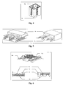
- the present invention relates to the connection between steel sheet by means of generating in the steel sheet a series of many small crown-shaped breakages ( Figure 1-1b ) oriented towards the side of the sheet which will remain in contact with the concrete (towards both sides alternately if needed, such that when fresh concrete is poured, the projections of said breakages are embedded therein.
- the present invention can be used to assure the connection of the metal section (with the inner concrete typical of a composite column. If the punching is towards the inside of the tube, before or after the section forming process, when the concrete is poured into the tube, the projections are embedded in the fresh concrete. Once the concrete sets, they assure the effective connection of the two materials and their composite working.
- the projections in the sheet are distributed in the most suitable areas, preferably the side flanks of the ribs, and as regularly as possible, to assure an effective connection with the concrete ( Figure 6-6b ). It does not lead to the relative vertical separation of the two materials since the sheet does not have the typical deep drawings of forged elements cooperating together, which cause the wedge effect that separates them. Furthermore, the bending strength of the sheet would be considerably maintained if the upper and lower planar bands are not perforated.
- the outer surface must be coated with a sealing layer (paint, impregnation, plastic film, vermiculite, etc.) which prevents fresh concrete from dripping while pouring the concrete.
- a sealing layer paint, impregnation, plastic film, vermiculite, etc.
- the application of the present invention is also envisaged for improving the adhesion between different concrete pouring phases.
- the device consists of a planar, corrugated, or any other section sheet , the projections having been made in alternating directions, i.e., towards both sides (faces) of the sheet (see Figure 4 ). Therefore, by placing the device on the free surface of the first concrete pouring phase, the breakage crowns oriented towards it act as anchors and those oriented towards the outside will act as anchors in the next concrete pouring phase in the case of planar devices.
- ribbed devices a part of the device is embedded in the concrete of the first concrete pouring phase and the other part is exposed to the air while waiting to be embedded in the concrete of the next phase.
- Examples 2 and 3 can be combined to design an auxiliary device which serves as a connection when pouring the concrete of composite slabs in two phases, useful in reducing the loads of the building phase (see Figure 7 ).
Landscapes
- Engineering & Computer Science (AREA)
- Architecture (AREA)
- Civil Engineering (AREA)
- Structural Engineering (AREA)
- Physics & Mathematics (AREA)
- Electromagnetism (AREA)
- Chemical & Material Sciences (AREA)
- Composite Materials (AREA)
- On-Site Construction Work That Accompanies The Preparation And Application Of Concrete (AREA)
- Joining Of Building Structures In Genera (AREA)
Abstract
Description
- The invention is comprised in the construction sector, particularly in the construction of concrete structures and composite steel-concrete structures.
- The common fault of composite steel-concrete structural elements, such as composite slabs for example, generally occurs due to the relative slipping or separation of the steel sheet and the concrete. The design difficulty of sheets for composite slabs resides in assuring their effectively composite performance; i.e., in designing retaining systems achieving high resistance to the separation and relative slipping of steel and concrete.
- Current sheet designs, such as that disclosed in patent
W009321405 FR2807081 - The forming angle defining the ribs of the slab, the position of the deep drawings, their depth, length, etc., are some of the important design parameters because the slipping resistance depends on them. The design and optimization process of this geometry, and also efficacy testing, are currently performed in an entirely empirical manner. The computation methods adopted according to worldwide standards for the calculation of composite slabs are also based on experimental parameters obtained from testing small standard models. These tests attempt to reproduce, more or less truthfully, the fault of relative slipping of steel and concrete.
- The doctoral dissertation entitled " Estudio Numérico y Experimental de la Interaction entre la Chapa de Acero y el Hormigón para la Mejora Resistente de las Losas mixtas frente al Deslizamiento longitudinal" (Numerical and Experimental Study of the Interaction between Steel Sheet and Concrete for the Improved Resistance of Composite Slabs to Longitudinal Slipping) by Miquel Ferrer Ballester and read on 8 March 2006 in the Universidad Politécnica de Cataluña (UPC), summarizes the prior art to date and is included in a line of research intended for improving the connection between the steel and concrete of current systems and devising innovative concepts which can mean complete connection without slipping.
- The present invention has been developed within the line of research in the Escuela Técnica Superior de Ingeniería Industrial of Barcelona (UPC), which substantially improves the relative connection problem of steel sheet and concrete both in the case of composite slabs and in other applications.
- The present invention relates to the connection between steel sheet by means of generating in the steel sheet a series of many small crown-shaped breakages (
Figure 1-1b ) oriented towards the side of the sheet which will remain in contact with the concrete (towards both sides alternately if needed, such that when fresh concrete is poured, the projections of said breakages are embedded therein. - When the concrete sets, these small breakages embedded therein have the function of resisting shearing stresses or separating stresses generated between both materials when the composite steel-concrete element is subjected to a load.
-
-
Figure 1 shows an example of steeply inclined projections caused by punching the sheet and a photograph of a prototype (case of planar sheet and crown-shaped breakages with 4 tips). -
Figure 2 shows the typologies of the punched through crown-shaped breakage of 3 and 4 tips. -
Figure 3 shows other breakage typologies (cylinder, cone, prism, diabolo). -
Figure 4 shows projections formed by breakages in alternating directions. -
Figure 5 shows the application to formed sections for composite columns or beams. -
Figure 6 shows the application to profiled sheets for composite slabs. -
Figure 7 shows the auxiliary device for pouring the concrete of composite slabs in two phases. - Figure 8 shows the auxiliary device for the connection between the metal section and the concrete in composite beams.
- The present invention is additionally illustrated by means of the following examples which are not intended to limit the scope thereof.
- In the case of cold-formed tubular sections, the present invention can be used to assure the connection of the metal section (with the inner concrete typical of a composite column. If the punching is towards the inside of the tube, before or after the section forming process, when the concrete is poured into the tube, the projections are embedded in the fresh concrete. Once the concrete sets, they assure the effective connection of the two materials and their composite working.
- In the case of composite slabs (forged elements cooperating together,
Figure 5 ), the projections in the sheet (Figure 6-6a ) are distributed in the most suitable areas, preferably the side flanks of the ribs, and as regularly as possible, to assure an effective connection with the concrete (Figure 6-6b ). It does not lead to the relative vertical separation of the two materials since the sheet does not have the typical deep drawings of forged elements cooperating together, which cause the wedge effect that separates them. Furthermore, the bending strength of the sheet would be considerably maintained if the upper and lower planar bands are not perforated. - In the event that the apertures associated with the breakages of the sheet are open enough, the outer surface must be coated with a sealing layer (paint, impregnation, plastic film, vermiculite, etc.) which prevents fresh concrete from dripping while pouring the concrete.
- The application of the present invention is also envisaged for improving the adhesion between different concrete pouring phases. The device consists of a planar, corrugated, or any other section sheet , the projections having been made in alternating directions, i.e., towards both sides (faces) of the sheet (see
Figure 4 ). Therefore, by placing the device on the free surface of the first concrete pouring phase, the breakage crowns oriented towards it act as anchors and those oriented towards the outside will act as anchors in the next concrete pouring phase in the case of planar devices. In the case of ribbed devices, a part of the device is embedded in the concrete of the first concrete pouring phase and the other part is exposed to the air while waiting to be embedded in the concrete of the next phase. - Examples 2 and 3 can be combined to design an auxiliary device which serves as a connection when pouring the concrete of composite slabs in two phases, useful in reducing the loads of the building phase (see
Figure 7 ). - Therefore, designing a device formed by a non-planar portion or sheet strip (corrugated, ribbed, etc.,) such that part of the device is immersed in the fresh concrete of the first phase (
Figure 7-7b ), being supported on the ribs of the ribbed sheet of the composite slab (Figure 7-7d ), and the other part being exposed above the free surface of the first concrete pouring is of interest. The complete sinkage of the sheet in the fresh concrete of the first phase -which would probably occur if the sheet was planar- is prevented and the existence of raised sectors which will be embedded in the concrete of the second concrete pouring phase (Figure 7-7c ), an efficient connection being assured.
Claims (13)
- A system for connection between steel sheet (Figure 1-1a), with a thickness equal to or less than 12 mm, and concrete, wherein the sheet has a repeated series of steeply inclined projections (Figure 1-1b) generated by local breakage of the sheet and oriented towards the side of the sheet in contact with the concrete, such that they are embedded therein after pouring the concrete, characterized in that said local breakages of the sheet are separated (Figure 1-1c) by a distance not less than the thickness thereof and not greater than 200 times said thickness, projecting from the surface of the sheet at a height between 0.1 and 50 times said thickness (Figure 1-1d), and the general size of the breakages (Figure 1-1e) is comprised between 0.5 and 100 times the thickness of the sheet.
- The system for connection according to claim 1, characterized in that the breakages have a crown shape in a configuration of 3 or more tips (Figure 2-2a, Figure 2-2b), depending on the process used to make the local breakages, for example, depending on the shape of the punch.
- The system for connection of claim 1, characterized in that the projections are arch-shaped.
- The system for connection of claim 1, characterized in that the projections are cone-shaped.
- The system for connection of claim 1, characterized in that the projections are diabolo-shaped.
- The system for connection of claim 1, characterized in that the projections are prismatic-shaped.
- The system for connection of claim 1, characterized in that the projections are pyramidal-shaped.
- The system for connection of the previous claims, characterized in that the shape of the projections is any combination described in claims 3 to 7, such that the breakages in the sheet occur at the edges indicated as 3e in the corresponding figures (Figure 3-3e).
- The system for connection of any of the previous claims, characterized in that the projections are alternately incorporated towards both sides of the sheet -the latter being planar, corrugated or of any other section- to be anchored to the concrete present on both sides thereof (Figure 4-4a and Figure 4-4b).
- A use of the new system for connection of any of the previous claims,, wherein the steel sheet is subjected to a forming process to become a structural element, for example, a closed tubular (Figure 5-5a), circular or rectangular section, for use as a composite column or composite beam, the effective connection between the metal section and concrete being assured (Figure 5-5b).
- A use of the new system for connection of any of the previous claims" wherein the steel sheet is subjected to a forming process to become a profiled sheet for composite slabs, whatever the shape of the section (for example Figure 6-6a), also referred to as forged elements cooperating together, the effective connection between the profiled sheet and the concrete thereof being assured (Figure 6-6b).
- A use of the new system for connection of any of the previous claims in a corrugated (Figure 7-7a), trapezoidal or any other non-planar section sheet device intended for anchoring two concrete pouring phases, such that the lower part of the section of the device is embedded in concrete of the first phase (Figure 7-7b) and the upper part is exposed while waiting for the concrete of the second phase, at which time it will be embedded therein (Figure 7-7c), for example, in the case of composite concrete slabs poured in two phases shown in Figure 7.
- A use of the new system for connection of any of the previous claims for the connection between the metal section (Figure 8-8a) and the concrete mass (Figure 8-8b) of an embedded composite or cantilever beam (cantilever case shown in Figure 8) by means of a planar (Figure 8-8c), corrugated, trapezoidal or any other section sheet device adhered by means of welding or other systems on the face or faces of the metal section which will remain in contact with the concrete, such that the projections incorporated in the sheet are embedded therein after pouring the concrete.
Priority Applications (1)
| Application Number | Priority Date | Filing Date | Title |
|---|---|---|---|
| PL09817308T PL2305911T3 (en) | 2008-06-16 | 2009-06-16 | System for connecting together sheet steel and concrete |
Applications Claiming Priority (2)
| Application Number | Priority Date | Filing Date | Title |
|---|---|---|---|
| ES200801846A ES2344389B2 (en) | 2008-06-16 | 2008-06-16 | SYSTEM FOR CONNECTION BETWEEN STEEL SHEET AND CONCRETE. |
| PCT/ES2009/000334 WO2010037876A1 (en) | 2008-06-16 | 2009-06-16 | System for connecting together sheet steel and concrete |
Publications (3)
| Publication Number | Publication Date |
|---|---|
| EP2305911A1 true EP2305911A1 (en) | 2011-04-06 |
| EP2305911A4 EP2305911A4 (en) | 2014-09-24 |
| EP2305911B1 EP2305911B1 (en) | 2018-04-18 |
Family
ID=42073021
Family Applications (1)
| Application Number | Title | Priority Date | Filing Date |
|---|---|---|---|
| EP09817308.1A Not-in-force EP2305911B1 (en) | 2008-06-16 | 2009-06-16 | System for connecting together sheet steel and concrete |
Country Status (5)
| Country | Link |
|---|---|
| EP (1) | EP2305911B1 (en) |
| ES (1) | ES2344389B2 (en) |
| PL (1) | PL2305911T3 (en) |
| PT (1) | PT2305911T (en) |
| WO (1) | WO2010037876A1 (en) |
Cited By (1)
| Publication number | Priority date | Publication date | Assignee | Title |
|---|---|---|---|---|
| CN106049747A (en) * | 2016-07-15 | 2016-10-26 | 中国矿业大学 | Honeycomb profiled steel sheet-concrete precast slab |
Families Citing this family (1)
| Publication number | Priority date | Publication date | Assignee | Title |
|---|---|---|---|---|
| CN113266098B (en) * | 2021-04-24 | 2022-07-12 | 广东省构建工程建设有限公司 | Novel large-span rib beam laminated slab and construction method |
Family Cites Families (16)
| Publication number | Priority date | Publication date | Assignee | Title |
|---|---|---|---|---|
| BE527707A (en) * | ||||
| GB190907952A (en) * | 1909-04-02 | 1910-03-10 | Carl Schutz | Improved Plate-stiffening for Ceilings, Poles, Columns and the like. |
| US3496691A (en) * | 1968-08-02 | 1970-02-24 | Bethlehem Steel Corp | Concrete forms |
| DE2159959C3 (en) * | 1971-12-03 | 1975-11-27 | Walter Dr.-Ing. 6101 Rossdorf Sowa | Sheet metal shuttering sheet used as reinforcement for a composite concrete ceiling |
| AT328145B (en) * | 1972-05-19 | 1976-03-10 | Bohm Beteiligungsgesellschaft | LOST SLAB FORMWORK |
| CH582801A5 (en) | 1973-08-04 | 1976-12-15 | Sowa Walter | |
| US4106249A (en) | 1977-06-30 | 1978-08-15 | Verco Manufacturing, Inc. | Method and apparatus for interlocking and venting a structural diaphragm |
| SU654780A1 (en) * | 1977-11-15 | 1979-03-30 | Украинский научно-исследовательский институт металлов | Reinforcement for concrete |
| US4251970A (en) * | 1978-05-30 | 1981-02-24 | Home Matti P | Thin sheet having punched-out adhesion projections for use in compound structures, and compound structures constructed therewith |
| DE3146188C1 (en) * | 1981-11-21 | 1983-06-09 | Werner Flosbach GmbH & Co KG, 5272 Wipperfürth | Device for attaching a layer of insulating material to a wall |
| DE3147087C2 (en) * | 1981-11-27 | 1985-03-07 | Max Dipl.-Ing. Dr.-Ing. 8700 Würzburg Mengeringhausen | Cantilever composite building panel and method for its manufacture |
| GB2201704B (en) * | 1987-02-26 | 1991-05-29 | Monier Ltd | Composite structures |
| AU627245B2 (en) * | 1988-12-09 | 1992-08-20 | John Lysaght (Australia) Limited | Profiled steel sheet |
| FI89961C (en) | 1992-04-13 | 1993-12-10 | Rannila Steel Oy | Connecting disc intended for a connecting plate |
| FR2807081B1 (en) | 2000-03-29 | 2002-09-13 | Pab Est | FORMING ELEMENT IN PROFILED STEEL SHEET FOR THE PRODUCTION OF A FLOOR WITH COLLABORATING METAL BINS |
| ITTV20020034A1 (en) * | 2002-04-04 | 2003-10-06 | Marcello Toncelli | REINFORCED SHEET IN CEMENTITIOUS CONGLOMERATE, PROCEDURE FOR SUABABRICATION AND RELATED STRENGTHENING STRUCTURE |
-
2008
- 2008-06-16 ES ES200801846A patent/ES2344389B2/en active Active
-
2009
- 2009-06-16 WO PCT/ES2009/000334 patent/WO2010037876A1/en not_active Ceased
- 2009-06-16 PT PT98173081T patent/PT2305911T/en unknown
- 2009-06-16 EP EP09817308.1A patent/EP2305911B1/en not_active Not-in-force
- 2009-06-16 PL PL09817308T patent/PL2305911T3/en unknown
Cited By (1)
| Publication number | Priority date | Publication date | Assignee | Title |
|---|---|---|---|---|
| CN106049747A (en) * | 2016-07-15 | 2016-10-26 | 中国矿业大学 | Honeycomb profiled steel sheet-concrete precast slab |
Also Published As
| Publication number | Publication date |
|---|---|
| ES2344389A1 (en) | 2010-08-25 |
| PL2305911T3 (en) | 2018-09-28 |
| ES2344389B2 (en) | 2011-06-02 |
| EP2305911B1 (en) | 2018-04-18 |
| PT2305911T (en) | 2018-07-17 |
| WO2010037876A1 (en) | 2010-04-08 |
| EP2305911A4 (en) | 2014-09-24 |
Similar Documents
| Publication | Publication Date | Title |
|---|---|---|
| US3728835A (en) | Composite concrete slab and steel joist construction | |
| US4295310A (en) | Precast concrete joist composite system | |
| US6003281A (en) | Reinforced concrete structural elements | |
| JP5131590B2 (en) | Column head PC girder temporary fixing structure in overhang construction method | |
| KR100585503B1 (en) | Shear connector using perforated and / or staggered steel sheets | |
| JP2001027005A (en) | Joint structure of steel member and concrete in composite structure | |
| JP2024503042A (en) | panelized serrated beam assembly | |
| US3434263A (en) | Shear link and method of using same | |
| KR101499337B1 (en) | Wide PC beam for slim floor | |
| EP2305911B1 (en) | System for connecting together sheet steel and concrete | |
| CN104619935A (en) | Point-supported element or flat concrete ceiling | |
| KR101024991B1 (en) | Hollow slab deck plate structure and construction method of hollow slab deck plate | |
| JP6253058B2 (en) | Reinforcing bar member and reinforced concrete structure using the reinforcing bar member | |
| KR200286012Y1 (en) | Concrete-Filled Steel Pipe Girder | |
| JPH073778A (en) | Rigid-connection joint of underground continuous wall | |
| KR101994089B1 (en) | Precast Concrete Slab With Pullout-Shear Resistance Elements Of Mesh Rib And Manufacturing Method Thereof | |
| GB2255358A (en) | Wall ties | |
| CN110904809A (en) | A T beam with a corrugated steel plate covered by a web | |
| RU2633624C1 (en) | Long-length steel concrete element | |
| CN215253690U (en) | A composite plate shear wall with vertical continuous bending steel bars | |
| JP3361789B2 (en) | Steel plate dowel and concrete filled steel pipe with corrugated stopper | |
| JPH0960194A (en) | Precast concrete structure | |
| RU185035U1 (en) | Steel concrete element | |
| JP2008063805A (en) | Connection structure of full precast concrete slab | |
| WO2016005660A1 (en) | Steel beam |
Legal Events
| Date | Code | Title | Description |
|---|---|---|---|
| PUAI | Public reference made under article 153(3) epc to a published international application that has entered the european phase |
Free format text: ORIGINAL CODE: 0009012 |
|
| 17P | Request for examination filed |
Effective date: 20110117 |
|
| AK | Designated contracting states |
Kind code of ref document: A1 Designated state(s): AT BE BG CH CY CZ DE DK EE ES FI FR GB GR HR HU IE IS IT LI LT LU LV MC MK MT NL NO PL PT RO SE SI SK TR |
|
| AX | Request for extension of the european patent |
Extension state: AL BA RS |
|
| DAX | Request for extension of the european patent (deleted) | ||
| A4 | Supplementary search report drawn up and despatched |
Effective date: 20140825 |
|
| RIC1 | Information provided on ipc code assigned before grant |
Ipc: E04B 5/40 20060101AFI20140819BHEP Ipc: E04C 5/12 20060101ALI20140819BHEP Ipc: E04C 2/08 20060101ALI20140819BHEP Ipc: E04C 2/32 20060101ALI20140819BHEP |
|
| 17Q | First examination report despatched |
Effective date: 20161021 |
|
| GRAP | Despatch of communication of intention to grant a patent |
Free format text: ORIGINAL CODE: EPIDOSNIGR1 |
|
| INTG | Intention to grant announced |
Effective date: 20171025 |
|
| GRAS | Grant fee paid |
Free format text: ORIGINAL CODE: EPIDOSNIGR3 |
|
| GRAA | (expected) grant |
Free format text: ORIGINAL CODE: 0009210 |
|
| AK | Designated contracting states |
Kind code of ref document: B1 Designated state(s): AT BE BG CH CY CZ DE DK EE ES FI FR GB GR HR HU IE IS IT LI LT LU LV MC MK MT NL NO PL PT RO SE SI SK TR |
|
| REG | Reference to a national code |
Ref country code: GB Ref legal event code: FG4D |
|
| REG | Reference to a national code |
Ref country code: CH Ref legal event code: EP |
|
| REG | Reference to a national code |
Ref country code: AT Ref legal event code: REF Ref document number: 990639 Country of ref document: AT Kind code of ref document: T Effective date: 20180515 |
|
| REG | Reference to a national code |
Ref country code: IE Ref legal event code: FG4D |
|
| REG | Reference to a national code |
Ref country code: DE Ref legal event code: R096 Ref document number: 602009051899 Country of ref document: DE |
|
| REG | Reference to a national code |
Ref country code: PT Ref legal event code: SC4A Ref document number: 2305911 Country of ref document: PT Date of ref document: 20180717 Kind code of ref document: T Free format text: AVAILABILITY OF NATIONAL TRANSLATION Effective date: 20180711 Ref country code: RO Ref legal event code: EPE |
|
| REG | Reference to a national code |
Ref country code: FR Ref legal event code: PLFP Year of fee payment: 10 |
|
| REG | Reference to a national code |
Ref country code: CH Ref legal event code: NV Representative=s name: STOLMAR AND PARTNER INTELLECTUAL PROPERTY S.A., CH |
|
| REG | Reference to a national code |
Ref country code: NL Ref legal event code: MP Effective date: 20180418 |
|
| REG | Reference to a national code |
Ref country code: LT Ref legal event code: MG4D |
|
| PG25 | Lapsed in a contracting state [announced via postgrant information from national office to epo] |
Ref country code: NL Free format text: LAPSE BECAUSE OF FAILURE TO SUBMIT A TRANSLATION OF THE DESCRIPTION OR TO PAY THE FEE WITHIN THE PRESCRIBED TIME-LIMIT Effective date: 20180418 |
|
| PG25 | Lapsed in a contracting state [announced via postgrant information from national office to epo] |
Ref country code: FI Free format text: LAPSE BECAUSE OF FAILURE TO SUBMIT A TRANSLATION OF THE DESCRIPTION OR TO PAY THE FEE WITHIN THE PRESCRIBED TIME-LIMIT Effective date: 20180418 Ref country code: BG Free format text: LAPSE BECAUSE OF FAILURE TO SUBMIT A TRANSLATION OF THE DESCRIPTION OR TO PAY THE FEE WITHIN THE PRESCRIBED TIME-LIMIT Effective date: 20180718 Ref country code: NO Free format text: LAPSE BECAUSE OF FAILURE TO SUBMIT A TRANSLATION OF THE DESCRIPTION OR TO PAY THE FEE WITHIN THE PRESCRIBED TIME-LIMIT Effective date: 20180718 Ref country code: ES Free format text: LAPSE BECAUSE OF FAILURE TO SUBMIT A TRANSLATION OF THE DESCRIPTION OR TO PAY THE FEE WITHIN THE PRESCRIBED TIME-LIMIT Effective date: 20180418 Ref country code: SE Free format text: LAPSE BECAUSE OF FAILURE TO SUBMIT A TRANSLATION OF THE DESCRIPTION OR TO PAY THE FEE WITHIN THE PRESCRIBED TIME-LIMIT Effective date: 20180418 Ref country code: LT Free format text: LAPSE BECAUSE OF FAILURE TO SUBMIT A TRANSLATION OF THE DESCRIPTION OR TO PAY THE FEE WITHIN THE PRESCRIBED TIME-LIMIT Effective date: 20180418 |
|
| PG25 | Lapsed in a contracting state [announced via postgrant information from national office to epo] |
Ref country code: LV Free format text: LAPSE BECAUSE OF FAILURE TO SUBMIT A TRANSLATION OF THE DESCRIPTION OR TO PAY THE FEE WITHIN THE PRESCRIBED TIME-LIMIT Effective date: 20180418 Ref country code: GR Free format text: LAPSE BECAUSE OF FAILURE TO SUBMIT A TRANSLATION OF THE DESCRIPTION OR TO PAY THE FEE WITHIN THE PRESCRIBED TIME-LIMIT Effective date: 20180719 Ref country code: HR Free format text: LAPSE BECAUSE OF FAILURE TO SUBMIT A TRANSLATION OF THE DESCRIPTION OR TO PAY THE FEE WITHIN THE PRESCRIBED TIME-LIMIT Effective date: 20180418 |
|
| REG | Reference to a national code |
Ref country code: AT Ref legal event code: MK05 Ref document number: 990639 Country of ref document: AT Kind code of ref document: T Effective date: 20180418 |
|
| REG | Reference to a national code |
Ref country code: DE Ref legal event code: R097 Ref document number: 602009051899 Country of ref document: DE |
|
| PG25 | Lapsed in a contracting state [announced via postgrant information from national office to epo] |
Ref country code: EE Free format text: LAPSE BECAUSE OF FAILURE TO SUBMIT A TRANSLATION OF THE DESCRIPTION OR TO PAY THE FEE WITHIN THE PRESCRIBED TIME-LIMIT Effective date: 20180418 Ref country code: AT Free format text: LAPSE BECAUSE OF FAILURE TO SUBMIT A TRANSLATION OF THE DESCRIPTION OR TO PAY THE FEE WITHIN THE PRESCRIBED TIME-LIMIT Effective date: 20180418 Ref country code: CZ Free format text: LAPSE BECAUSE OF FAILURE TO SUBMIT A TRANSLATION OF THE DESCRIPTION OR TO PAY THE FEE WITHIN THE PRESCRIBED TIME-LIMIT Effective date: 20180418 Ref country code: SK Free format text: LAPSE BECAUSE OF FAILURE TO SUBMIT A TRANSLATION OF THE DESCRIPTION OR TO PAY THE FEE WITHIN THE PRESCRIBED TIME-LIMIT Effective date: 20180418 Ref country code: DK Free format text: LAPSE BECAUSE OF FAILURE TO SUBMIT A TRANSLATION OF THE DESCRIPTION OR TO PAY THE FEE WITHIN THE PRESCRIBED TIME-LIMIT Effective date: 20180418 |
|
| PLBE | No opposition filed within time limit |
Free format text: ORIGINAL CODE: 0009261 |
|
| STAA | Information on the status of an ep patent application or granted ep patent |
Free format text: STATUS: NO OPPOSITION FILED WITHIN TIME LIMIT |
|
| PG25 | Lapsed in a contracting state [announced via postgrant information from national office to epo] |
Ref country code: IT Free format text: LAPSE BECAUSE OF FAILURE TO SUBMIT A TRANSLATION OF THE DESCRIPTION OR TO PAY THE FEE WITHIN THE PRESCRIBED TIME-LIMIT Effective date: 20180418 |
|
| REG | Reference to a national code |
Ref country code: IE Ref legal event code: MM4A |
|
| 26N | No opposition filed |
Effective date: 20190121 |
|
| PG25 | Lapsed in a contracting state [announced via postgrant information from national office to epo] |
Ref country code: MC Free format text: LAPSE BECAUSE OF FAILURE TO SUBMIT A TRANSLATION OF THE DESCRIPTION OR TO PAY THE FEE WITHIN THE PRESCRIBED TIME-LIMIT Effective date: 20180418 |
|
| PG25 | Lapsed in a contracting state [announced via postgrant information from national office to epo] |
Ref country code: IE Free format text: LAPSE BECAUSE OF NON-PAYMENT OF DUE FEES Effective date: 20180616 |
|
| PG25 | Lapsed in a contracting state [announced via postgrant information from national office to epo] |
Ref country code: SI Free format text: LAPSE BECAUSE OF FAILURE TO SUBMIT A TRANSLATION OF THE DESCRIPTION OR TO PAY THE FEE WITHIN THE PRESCRIBED TIME-LIMIT Effective date: 20180418 |
|
| PG25 | Lapsed in a contracting state [announced via postgrant information from national office to epo] |
Ref country code: MT Free format text: LAPSE BECAUSE OF NON-PAYMENT OF DUE FEES Effective date: 20180616 |
|
| PG25 | Lapsed in a contracting state [announced via postgrant information from national office to epo] |
Ref country code: TR Free format text: LAPSE BECAUSE OF FAILURE TO SUBMIT A TRANSLATION OF THE DESCRIPTION OR TO PAY THE FEE WITHIN THE PRESCRIBED TIME-LIMIT Effective date: 20180418 |
|
| PG25 | Lapsed in a contracting state [announced via postgrant information from national office to epo] |
Ref country code: HU Free format text: LAPSE BECAUSE OF FAILURE TO SUBMIT A TRANSLATION OF THE DESCRIPTION OR TO PAY THE FEE WITHIN THE PRESCRIBED TIME-LIMIT; INVALID AB INITIO Effective date: 20090616 |
|
| PG25 | Lapsed in a contracting state [announced via postgrant information from national office to epo] |
Ref country code: CY Free format text: LAPSE BECAUSE OF FAILURE TO SUBMIT A TRANSLATION OF THE DESCRIPTION OR TO PAY THE FEE WITHIN THE PRESCRIBED TIME-LIMIT Effective date: 20180418 Ref country code: MK Free format text: LAPSE BECAUSE OF NON-PAYMENT OF DUE FEES Effective date: 20180418 |
|
| PG25 | Lapsed in a contracting state [announced via postgrant information from national office to epo] |
Ref country code: IS Free format text: LAPSE BECAUSE OF FAILURE TO SUBMIT A TRANSLATION OF THE DESCRIPTION OR TO PAY THE FEE WITHIN THE PRESCRIBED TIME-LIMIT Effective date: 20180818 |
|
| PGFP | Annual fee paid to national office [announced via postgrant information from national office to epo] |
Ref country code: LU Payment date: 20210628 Year of fee payment: 13 Ref country code: DE Payment date: 20210629 Year of fee payment: 13 Ref country code: FR Payment date: 20210625 Year of fee payment: 13 Ref country code: RO Payment date: 20210623 Year of fee payment: 13 Ref country code: PT Payment date: 20210625 Year of fee payment: 13 |
|
| PGFP | Annual fee paid to national office [announced via postgrant information from national office to epo] |
Ref country code: GB Payment date: 20210628 Year of fee payment: 13 Ref country code: BE Payment date: 20210630 Year of fee payment: 13 |
|
| PGFP | Annual fee paid to national office [announced via postgrant information from national office to epo] |
Ref country code: CH Payment date: 20210702 Year of fee payment: 13 Ref country code: PL Payment date: 20210707 Year of fee payment: 13 |
|
| REG | Reference to a national code |
Ref country code: DE Ref legal event code: R119 Ref document number: 602009051899 Country of ref document: DE |
|
| PG25 | Lapsed in a contracting state [announced via postgrant information from national office to epo] |
Ref country code: RO Free format text: LAPSE BECAUSE OF NON-PAYMENT OF DUE FEES Effective date: 20220616 Ref country code: PT Free format text: LAPSE BECAUSE OF NON-PAYMENT OF DUE FEES Effective date: 20221216 |
|
| REG | Reference to a national code |
Ref country code: CH Ref legal event code: PL |
|
| REG | Reference to a national code |
Ref country code: BE Ref legal event code: MM Effective date: 20220630 |
|
| GBPC | Gb: european patent ceased through non-payment of renewal fee |
Effective date: 20220616 |
|
| PG25 | Lapsed in a contracting state [announced via postgrant information from national office to epo] |
Ref country code: LU Free format text: LAPSE BECAUSE OF NON-PAYMENT OF DUE FEES Effective date: 20220616 Ref country code: LI Free format text: LAPSE BECAUSE OF NON-PAYMENT OF DUE FEES Effective date: 20220630 Ref country code: FR Free format text: LAPSE BECAUSE OF NON-PAYMENT OF DUE FEES Effective date: 20220630 Ref country code: CH Free format text: LAPSE BECAUSE OF NON-PAYMENT OF DUE FEES Effective date: 20220630 |
|
| PG25 | Lapsed in a contracting state [announced via postgrant information from national office to epo] |
Ref country code: GB Free format text: LAPSE BECAUSE OF NON-PAYMENT OF DUE FEES Effective date: 20220616 Ref country code: DE Free format text: LAPSE BECAUSE OF NON-PAYMENT OF DUE FEES Effective date: 20230103 Ref country code: BE Free format text: LAPSE BECAUSE OF NON-PAYMENT OF DUE FEES Effective date: 20220630 |
|
| PG25 | Lapsed in a contracting state [announced via postgrant information from national office to epo] |
Ref country code: PL Free format text: LAPSE BECAUSE OF NON-PAYMENT OF DUE FEES Effective date: 20220616 |