EP2305852A1 - Single layer bond coat and method of application - Google Patents
Single layer bond coat and method of application Download PDFInfo
- Publication number
- EP2305852A1 EP2305852A1 EP10179700A EP10179700A EP2305852A1 EP 2305852 A1 EP2305852 A1 EP 2305852A1 EP 10179700 A EP10179700 A EP 10179700A EP 10179700 A EP10179700 A EP 10179700A EP 2305852 A1 EP2305852 A1 EP 2305852A1
- Authority
- EP
- European Patent Office
- Prior art keywords
- bond coat
- single layer
- range
- particles
- coat
- Prior art date
- Legal status (The legal status is an assumption and is not a legal conclusion. Google has not performed a legal analysis and makes no representation as to the accuracy of the status listed.)
- Granted
Links
Images


Classifications
-
- F—MECHANICAL ENGINEERING; LIGHTING; HEATING; WEAPONS; BLASTING
- F01—MACHINES OR ENGINES IN GENERAL; ENGINE PLANTS IN GENERAL; STEAM ENGINES
- F01D—NON-POSITIVE DISPLACEMENT MACHINES OR ENGINES, e.g. STEAM TURBINES
- F01D5/00—Blades; Blade-carrying members; Heating, heat-insulating, cooling or antivibration means on the blades or the members
- F01D5/12—Blades
- F01D5/28—Selecting particular materials; Particular measures relating thereto; Measures against erosion or corrosion
- F01D5/288—Protective coatings for blades
-
- C—CHEMISTRY; METALLURGY
- C23—COATING METALLIC MATERIAL; COATING MATERIAL WITH METALLIC MATERIAL; CHEMICAL SURFACE TREATMENT; DIFFUSION TREATMENT OF METALLIC MATERIAL; COATING BY VACUUM EVAPORATION, BY SPUTTERING, BY ION IMPLANTATION OR BY CHEMICAL VAPOUR DEPOSITION, IN GENERAL; INHIBITING CORROSION OF METALLIC MATERIAL OR INCRUSTATION IN GENERAL
- C23C—COATING METALLIC MATERIAL; COATING MATERIAL WITH METALLIC MATERIAL; SURFACE TREATMENT OF METALLIC MATERIAL BY DIFFUSION INTO THE SURFACE, BY CHEMICAL CONVERSION OR SUBSTITUTION; COATING BY VACUUM EVAPORATION, BY SPUTTERING, BY ION IMPLANTATION OR BY CHEMICAL VAPOUR DEPOSITION, IN GENERAL
- C23C28/00—Coating for obtaining at least two superposed coatings either by methods not provided for in a single one of groups C23C2/00 - C23C26/00 or by combinations of methods provided for in subclasses C23C and C25C or C25D
- C23C28/30—Coatings combining at least one metallic layer and at least one inorganic non-metallic layer
- C23C28/32—Coatings combining at least one metallic layer and at least one inorganic non-metallic layer including at least one pure metallic layer
- C23C28/321—Coatings combining at least one metallic layer and at least one inorganic non-metallic layer including at least one pure metallic layer with at least one metal alloy layer
- C23C28/3215—Coatings combining at least one metallic layer and at least one inorganic non-metallic layer including at least one pure metallic layer with at least one metal alloy layer at least one MCrAlX layer
-
- C—CHEMISTRY; METALLURGY
- C23—COATING METALLIC MATERIAL; COATING MATERIAL WITH METALLIC MATERIAL; CHEMICAL SURFACE TREATMENT; DIFFUSION TREATMENT OF METALLIC MATERIAL; COATING BY VACUUM EVAPORATION, BY SPUTTERING, BY ION IMPLANTATION OR BY CHEMICAL VAPOUR DEPOSITION, IN GENERAL; INHIBITING CORROSION OF METALLIC MATERIAL OR INCRUSTATION IN GENERAL
- C23C—COATING METALLIC MATERIAL; COATING MATERIAL WITH METALLIC MATERIAL; SURFACE TREATMENT OF METALLIC MATERIAL BY DIFFUSION INTO THE SURFACE, BY CHEMICAL CONVERSION OR SUBSTITUTION; COATING BY VACUUM EVAPORATION, BY SPUTTERING, BY ION IMPLANTATION OR BY CHEMICAL VAPOUR DEPOSITION, IN GENERAL
- C23C28/00—Coating for obtaining at least two superposed coatings either by methods not provided for in a single one of groups C23C2/00 - C23C26/00 or by combinations of methods provided for in subclasses C23C and C25C or C25D
- C23C28/30—Coatings combining at least one metallic layer and at least one inorganic non-metallic layer
- C23C28/34—Coatings combining at least one metallic layer and at least one inorganic non-metallic layer including at least one inorganic non-metallic material layer, e.g. metal carbide, nitride, boride, silicide layer and their mixtures, enamels, phosphates and sulphates
- C23C28/345—Coatings combining at least one metallic layer and at least one inorganic non-metallic layer including at least one inorganic non-metallic material layer, e.g. metal carbide, nitride, boride, silicide layer and their mixtures, enamels, phosphates and sulphates with at least one oxide layer
- C23C28/3455—Coatings combining at least one metallic layer and at least one inorganic non-metallic layer including at least one inorganic non-metallic material layer, e.g. metal carbide, nitride, boride, silicide layer and their mixtures, enamels, phosphates and sulphates with at least one oxide layer with a refractory ceramic layer, e.g. refractory metal oxide, ZrO2, rare earth oxides or a thermal barrier system comprising at least one refractory oxide layer
-
- C—CHEMISTRY; METALLURGY
- C23—COATING METALLIC MATERIAL; COATING MATERIAL WITH METALLIC MATERIAL; CHEMICAL SURFACE TREATMENT; DIFFUSION TREATMENT OF METALLIC MATERIAL; COATING BY VACUUM EVAPORATION, BY SPUTTERING, BY ION IMPLANTATION OR BY CHEMICAL VAPOUR DEPOSITION, IN GENERAL; INHIBITING CORROSION OF METALLIC MATERIAL OR INCRUSTATION IN GENERAL
- C23C—COATING METALLIC MATERIAL; COATING MATERIAL WITH METALLIC MATERIAL; SURFACE TREATMENT OF METALLIC MATERIAL BY DIFFUSION INTO THE SURFACE, BY CHEMICAL CONVERSION OR SUBSTITUTION; COATING BY VACUUM EVAPORATION, BY SPUTTERING, BY ION IMPLANTATION OR BY CHEMICAL VAPOUR DEPOSITION, IN GENERAL
- C23C4/00—Coating by spraying the coating material in the molten state, e.g. by flame, plasma or electric discharge
- C23C4/04—Coating by spraying the coating material in the molten state, e.g. by flame, plasma or electric discharge characterised by the coating material
- C23C4/06—Metallic material
- C23C4/073—Metallic material containing MCrAl or MCrAlY alloys, where M is nickel, cobalt or iron, with or without non-metal elements
-
- C—CHEMISTRY; METALLURGY
- C23—COATING METALLIC MATERIAL; COATING MATERIAL WITH METALLIC MATERIAL; CHEMICAL SURFACE TREATMENT; DIFFUSION TREATMENT OF METALLIC MATERIAL; COATING BY VACUUM EVAPORATION, BY SPUTTERING, BY ION IMPLANTATION OR BY CHEMICAL VAPOUR DEPOSITION, IN GENERAL; INHIBITING CORROSION OF METALLIC MATERIAL OR INCRUSTATION IN GENERAL
- C23C—COATING METALLIC MATERIAL; COATING MATERIAL WITH METALLIC MATERIAL; SURFACE TREATMENT OF METALLIC MATERIAL BY DIFFUSION INTO THE SURFACE, BY CHEMICAL CONVERSION OR SUBSTITUTION; COATING BY VACUUM EVAPORATION, BY SPUTTERING, BY ION IMPLANTATION OR BY CHEMICAL VAPOUR DEPOSITION, IN GENERAL
- C23C4/00—Coating by spraying the coating material in the molten state, e.g. by flame, plasma or electric discharge
- C23C4/12—Coating by spraying the coating material in the molten state, e.g. by flame, plasma or electric discharge characterised by the method of spraying
- C23C4/129—Flame spraying
-
- C—CHEMISTRY; METALLURGY
- C23—COATING METALLIC MATERIAL; COATING MATERIAL WITH METALLIC MATERIAL; CHEMICAL SURFACE TREATMENT; DIFFUSION TREATMENT OF METALLIC MATERIAL; COATING BY VACUUM EVAPORATION, BY SPUTTERING, BY ION IMPLANTATION OR BY CHEMICAL VAPOUR DEPOSITION, IN GENERAL; INHIBITING CORROSION OF METALLIC MATERIAL OR INCRUSTATION IN GENERAL
- C23C—COATING METALLIC MATERIAL; COATING MATERIAL WITH METALLIC MATERIAL; SURFACE TREATMENT OF METALLIC MATERIAL BY DIFFUSION INTO THE SURFACE, BY CHEMICAL CONVERSION OR SUBSTITUTION; COATING BY VACUUM EVAPORATION, BY SPUTTERING, BY ION IMPLANTATION OR BY CHEMICAL VAPOUR DEPOSITION, IN GENERAL
- C23C4/00—Coating by spraying the coating material in the molten state, e.g. by flame, plasma or electric discharge
- C23C4/12—Coating by spraying the coating material in the molten state, e.g. by flame, plasma or electric discharge characterised by the method of spraying
- C23C4/134—Plasma spraying
-
- F—MECHANICAL ENGINEERING; LIGHTING; HEATING; WEAPONS; BLASTING
- F02—COMBUSTION ENGINES; HOT-GAS OR COMBUSTION-PRODUCT ENGINE PLANTS
- F02F—CYLINDERS, PISTONS OR CASINGS, FOR COMBUSTION ENGINES; ARRANGEMENTS OF SEALINGS IN COMBUSTION ENGINES
- F02F3/00—Pistons
- F02F3/10—Pistons having surface coverings
- F02F3/12—Pistons having surface coverings on piston heads
-
- Y—GENERAL TAGGING OF NEW TECHNOLOGICAL DEVELOPMENTS; GENERAL TAGGING OF CROSS-SECTIONAL TECHNOLOGIES SPANNING OVER SEVERAL SECTIONS OF THE IPC; TECHNICAL SUBJECTS COVERED BY FORMER USPC CROSS-REFERENCE ART COLLECTIONS [XRACs] AND DIGESTS
- Y10—TECHNICAL SUBJECTS COVERED BY FORMER USPC
- Y10S—TECHNICAL SUBJECTS COVERED BY FORMER USPC CROSS-REFERENCE ART COLLECTIONS [XRACs] AND DIGESTS
- Y10S428/00—Stock material or miscellaneous articles
- Y10S428/922—Static electricity metal bleed-off metallic stock
- Y10S428/9335—Product by special process
- Y10S428/937—Sprayed metal
-
- Y—GENERAL TAGGING OF NEW TECHNOLOGICAL DEVELOPMENTS; GENERAL TAGGING OF CROSS-SECTIONAL TECHNOLOGIES SPANNING OVER SEVERAL SECTIONS OF THE IPC; TECHNICAL SUBJECTS COVERED BY FORMER USPC CROSS-REFERENCE ART COLLECTIONS [XRACs] AND DIGESTS
- Y10—TECHNICAL SUBJECTS COVERED BY FORMER USPC
- Y10T—TECHNICAL SUBJECTS COVERED BY FORMER US CLASSIFICATION
- Y10T428/00—Stock material or miscellaneous articles
- Y10T428/12—All metal or with adjacent metals
- Y10T428/12472—Microscopic interfacial wave or roughness
-
- Y—GENERAL TAGGING OF NEW TECHNOLOGICAL DEVELOPMENTS; GENERAL TAGGING OF CROSS-SECTIONAL TECHNOLOGIES SPANNING OVER SEVERAL SECTIONS OF THE IPC; TECHNICAL SUBJECTS COVERED BY FORMER USPC CROSS-REFERENCE ART COLLECTIONS [XRACs] AND DIGESTS
- Y10—TECHNICAL SUBJECTS COVERED BY FORMER USPC
- Y10T—TECHNICAL SUBJECTS COVERED BY FORMER US CLASSIFICATION
- Y10T428/00—Stock material or miscellaneous articles
- Y10T428/12—All metal or with adjacent metals
- Y10T428/12493—Composite; i.e., plural, adjacent, spatially distinct metal components [e.g., layers, joint, etc.]
- Y10T428/12535—Composite; i.e., plural, adjacent, spatially distinct metal components [e.g., layers, joint, etc.] with additional, spatially distinct nonmetal component
-
- Y—GENERAL TAGGING OF NEW TECHNOLOGICAL DEVELOPMENTS; GENERAL TAGGING OF CROSS-SECTIONAL TECHNOLOGIES SPANNING OVER SEVERAL SECTIONS OF THE IPC; TECHNICAL SUBJECTS COVERED BY FORMER USPC CROSS-REFERENCE ART COLLECTIONS [XRACs] AND DIGESTS
- Y10—TECHNICAL SUBJECTS COVERED BY FORMER USPC
- Y10T—TECHNICAL SUBJECTS COVERED BY FORMER US CLASSIFICATION
- Y10T428/00—Stock material or miscellaneous articles
- Y10T428/12—All metal or with adjacent metals
- Y10T428/12493—Composite; i.e., plural, adjacent, spatially distinct metal components [e.g., layers, joint, etc.]
- Y10T428/12535—Composite; i.e., plural, adjacent, spatially distinct metal components [e.g., layers, joint, etc.] with additional, spatially distinct nonmetal component
- Y10T428/12611—Oxide-containing component
-
- Y—GENERAL TAGGING OF NEW TECHNOLOGICAL DEVELOPMENTS; GENERAL TAGGING OF CROSS-SECTIONAL TECHNOLOGIES SPANNING OVER SEVERAL SECTIONS OF THE IPC; TECHNICAL SUBJECTS COVERED BY FORMER USPC CROSS-REFERENCE ART COLLECTIONS [XRACs] AND DIGESTS
- Y10—TECHNICAL SUBJECTS COVERED BY FORMER USPC
- Y10T—TECHNICAL SUBJECTS COVERED BY FORMER US CLASSIFICATION
- Y10T428/00—Stock material or miscellaneous articles
- Y10T428/12—All metal or with adjacent metals
- Y10T428/12493—Composite; i.e., plural, adjacent, spatially distinct metal components [e.g., layers, joint, etc.]
- Y10T428/12771—Transition metal-base component
- Y10T428/12861—Group VIII or IB metal-base component
- Y10T428/12931—Co-, Fe-, or Ni-base components, alternative to each other
-
- Y—GENERAL TAGGING OF NEW TECHNOLOGICAL DEVELOPMENTS; GENERAL TAGGING OF CROSS-SECTIONAL TECHNOLOGIES SPANNING OVER SEVERAL SECTIONS OF THE IPC; TECHNICAL SUBJECTS COVERED BY FORMER USPC CROSS-REFERENCE ART COLLECTIONS [XRACs] AND DIGESTS
- Y10—TECHNICAL SUBJECTS COVERED BY FORMER USPC
- Y10T—TECHNICAL SUBJECTS COVERED BY FORMER US CLASSIFICATION
- Y10T428/00—Stock material or miscellaneous articles
- Y10T428/12—All metal or with adjacent metals
- Y10T428/12493—Composite; i.e., plural, adjacent, spatially distinct metal components [e.g., layers, joint, etc.]
- Y10T428/12771—Transition metal-base component
- Y10T428/12861—Group VIII or IB metal-base component
- Y10T428/12937—Co- or Ni-base component next to Fe-base component
-
- Y—GENERAL TAGGING OF NEW TECHNOLOGICAL DEVELOPMENTS; GENERAL TAGGING OF CROSS-SECTIONAL TECHNOLOGIES SPANNING OVER SEVERAL SECTIONS OF THE IPC; TECHNICAL SUBJECTS COVERED BY FORMER USPC CROSS-REFERENCE ART COLLECTIONS [XRACs] AND DIGESTS
- Y10—TECHNICAL SUBJECTS COVERED BY FORMER USPC
- Y10T—TECHNICAL SUBJECTS COVERED BY FORMER US CLASSIFICATION
- Y10T428/00—Stock material or miscellaneous articles
- Y10T428/12—All metal or with adjacent metals
- Y10T428/12993—Surface feature [e.g., rough, mirror]
Definitions
- the present invention relates generally to protective coatings applied to metal substrates. More specifically, the invention is directed to a single layer bond coat having the benefits of conventional bi-layer bond coats, and to the related method for application of such single layer bond coats.
- TBC thermal barrier coating
- TBC systems must have low thermal conductivity, strongly adhere to the article, and remain adherent throughout many heating and cooling cycles. The latter requirement is particularly demanding due to the different coefficients of thermal expansion between materials having low thermal conductivity and superalloy materials typically used to form turbine engine components.
- TBC systems capable of satisfying the above requirements generally require a metallic bond coat deposited on the component surface, followed by an adherent thermal barrier ceramic layer that serves to thermally insulate the component.
- Various ceramic materials have been employed as the thermal barrier layer, particularly zirconia (ZrO 2 ) stabilized by yttria (Y 2 O 3 ), magnesia (MgO), ceria (CeO 2 ), scandia (Sc 2 O 3 ), or another oxide.
- the bond coat is typically formed from an oxidation-resistant aluminum-containing alloy to promote adhesion of the ceramic layer to the component and inhibit oxidation of the underlying superalloy.
- Examples of prior art bond coats include overlay coatings such as MCrAlY (where M is iron, cobalt and/or nickel), and diffusion coatings such as diffusion aluminide or platinum aluminide, which are oxidation-resistant aluminum-base intermetallics.
- the bond coat is typically disposed on the substrate by a thermal spray processes, such as vacuum plasma spray (VPS) (also know as low pressure plasma spraying (LPPS)), air plasma spray (APS), and high velocity oxy-fuel (HVOF) spray processes.
- VPS vacuum plasma spray
- LPPS low pressure plasma spraying
- APS air plasma spray
- HVOF high velocity oxy-fuel
- a coarse powder layer is then deposited over the fine powder layer to achieve a desired degree of surface roughness for adequate adhesion of the ceramic material.
- APS bond coating techniques are often favored for the coarse powder layer due to lower equipment cost and ease of application and masking. Adhesion of the ceramic material layer to an APS bond coat is promoted by forming the bond coat to have a surface roughness of about 200 microinches (about 5 ⁇ m) to about 500 microinches (about 13 ⁇ m) Ra (Arithmetic Average Roughness (Ra) as determined from ANSI/ASME Standard B461-1985).
- the coarse powder layer is generally unsuitable as a protective coating system.
- the coarse powder layer is relatively porous and prone to oxidation damage.
- the art would benefit from an improved commercially viable process for applying a single layer bond coat from a single powder composition, with the bond coat having the desired properties of conventional bi-layer bond coats.
- the present invention provides a protective coating system for a metal substrate, and is particularly suited for metal components of a gas turbine engine.
- the system includes a superalloy metal substrate having a single layer bond coat applied to the substrate.
- the bond coat is applied in a thermal spray process, for example a high velocity oxy-fuel (HVOF) process, from a homogeneous powder composition that results in a bond coat having properties comparable to bi-layer bond coats.
- the powder composition has a particle size distribution wherein about 90% of the particles by volume are within a range of about 10 ⁇ m to about 100 ⁇ m.
- the particles are distributed relatively uniformly within the range in that the percentage of particles within any 10 ⁇ m band within the range does not exceed about 20% by volume, and the percentage of particles within any two adjacent 10 ⁇ m bands within the range does not deviate by more than about 8% by volume.
- the coating system may also encompass a ceramic thermal barrier layer applied to the single layer bond coat, or the bond coat may be the only layer of the protective coating system.
- the present invention also encompasses a method for forming a protective coating system on a metal substrate.
- the method includes applying a single layer bond coat to a superalloy metal substrate, such as a Ni or Co based superalloy, in a thermal spray process, for example an HVOF process, from a homogeneous powder composition having a particle size distribution such that the resulting bond coat has properties at least comparable to bi-layer bond coats.
- About 90% by volume of the particles are within a range of about 10 ⁇ m to about 100 ⁇ m.
- the percentage of particles within any 10 ⁇ m band within the range does not exceed about 20% by volume, and the percentage of particles within any two adjacent 10 ⁇ m bands within the range does not deviate by more than about 8% by volume.
- a single layer bond coat formed in accordance with the present method may have a surface roughness of at least about 300 ⁇ inch Ra, a density of at least about 90% of theoretical density; and a bond coat to substrate tensile strength of at least about 6.0 ksi.
- the bond coat powder composition may include MCrAlY alloy particles, where M is at least one of iron, cobalt, or nickel.
- a ceramic thermal barrier layer is applied over the single layer bond coat, with a thermal barrier layer to bond coat tensile strength that exceeds the cohesive strength of the ceramic layer, regardless of the morphology of the ceramic layer.
- This ceramic barrier layer may be formed from, for example, commercially available yttria stabilized ceramic coating particles.
- thermal barrier coating (TBC) systems are often used to improve the efficiency and performance of metal parts which are exposed to high temperatures, such as nozzles, buckets, shrouds, airfoils, and other gas turbine components.
- the combustion gas temperatures present in conventional gas turbines are maintained as high as possible for operating efficiency, and turbine combustion components and other elements of the engine are usually made of alloys which can resist the high temperature environment, e.g., superalloys, which have an operating temperature limit of about 1000-1150 degrees Celsius.
- the TBC systems effectively increase the operating temperature of the turbine by maintaining or reducing the surface temperature of the alloys used to form the various engine components.
- TBC systems are also critical for protecting the surfaces of various turbine components.
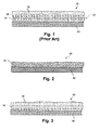
- most conventional TBC systems 30 are dual-layer systems that include a ceramic-based top layer 38 deposited over a denser, oxidation-resistant bi-layer bond coat 32.
- the ceramic material is typically a material like zirconia (zirconium oxide), which is usually chemically stabilized with another material such as yttria.
- the bond coat 32 is applied to a metal substrate 40 as a bi-layer construction wherein a fine powder is first deposited on the substrate to form a dense, low oxide layer 34. A coarse powder layer 36 is then deposited over the fine powder layer to achieve a desired degree of surface roughness for adequate adhesion of the ceramic material 38.
- the present invention relates to a protective coating system 50 having an improved, single layer bond coat (SLBC) 54 applied to a metal substrate 40.
- SLBC single layer bond coat
- the SLBC 54 will typically form the initial layer in a TBC system
- a bond coat 54 in accordance with the present invention may also be used as a stand-alone protective overlay coating on any manner of metallic substrate, i.e., without a ceramic top layer, as depicted in Fig. 2.
- Fig. 3 depicts a protective coating system 50 in accordance with the invention that includes a ceramic layer 38 applied over the SLBC 54.
- Single layer bond coatings 54 in accordance with the invention may be applied to components of a gas turbine, as discussed above, or used in other environments, such as selected components of diesel or other types of internal combustion engines.
- Fig. 4 is provided for purposes of illustrating an environment in which the present invention is particularly useful, and depicts a conventional gas turbine blade configuration 10.
- a plurality of the blades 10 are attached to an annular rotor disk (not shown) in a gas turbine.
- Blade 10 includes an airfoil 12, having pressure and suction sides 14, 16, and leading and trailing edges 18 and 20.
- the lower part of the airfoil terminates with base 22.
- Base 22 includes a platform 24, in which the airfoil can be rigidly mounted in an upright position, i.e., substantially vertical to the top surface 25 of the platform.
- the base further includes a dovetail root 26, attached to the underside of the platform, for attaching blade 10 to the rotor.
- the airfoil 12 is at least one component that typically requires a thermal barrier
- the SLBC 54 is applied to any manner of metal substrate 40 in a thermal spray process from a homogeneous powder composition having a particle size distribution that provides the SLBC 54 with comparable characteristics of a bi-layer bond coat.
- the SLBC 54 has the density and low oxide content of a fine powder layer comparable to layer 34 of Fig. 1 , and the surface roughness of a coarse powder layer comparable to layer 36 of Fig. 1 .
- a homogeneous powder composition used in the thermal spray process to apply the SLBC 54 has the particle size characteristics of, for example, graphs C, D, or E in that about 90% of the particles by volume are within a range of about 10 ⁇ m to about 100 ⁇ m.
- the percentage of particles within any 10 ⁇ m band within the range does not exceed about 20% by volume, and the percentage of particles within any two adjacent 10 ⁇ m bands within the range does not deviate by more than about 8% by volume.
- the particles within any 10 ⁇ m do not exceed about 13 % by volume of the composition, and such percentage does not deviate across the range.
- the percentage of particles within the band of 20 to 30 ⁇ m is the same as the percentage of particles within the band of 30 to 40 ⁇ m, and so forth.
- the graph C in Fig. 5 is considered "ideal" because of its flat, truncated profile wherein the percentage of particles within the 10 ⁇ m bands is the same across the stated range (i.e., range of about 10 ⁇ m to about 100 ⁇ m).
- this profile may not be economically feasible or otherwise attainable with blends or mixtures of commercially available powders.
- a more realistic particle size distribution may be reflected by, for example, graph D.
- This profile has a "bi-modal" aspect in that distinct fine and coarse particle peaks are identifiable, yet the overall profile still satisfies the requirements set forth above.
- Graph A in Fig. 5 illustrates a typical particle size distribution curve for conventional fine particles used to form an initial layer 34 ( Fig. 1 ) in conventional TBC systems, and is provided for purposes of comparison with curves for powder compositions in accordance with the present invention .
- Conventional fine powders have a particle size distribution range of generally about -53+22 ⁇ m (d10 percentile of approximately 22 ⁇ m; d90 percentile of approximately 53 ⁇ m).
- Commercial HVOF powders are typically in the range of about -45+10 ⁇ m.
- Graph B is a typical particle size distribution curve for coarse powders used to form the second layer 36 of conventional bond coats 32 ( Fig. 1 ), and is also provided for comparative purposes. These coarse powders have a particle size distribution range of about -100+44 ⁇ m (d10 percentile of approximately 44 ⁇ m; d90 percentile of approximately 100 ⁇ m).
- Graph E in Fig. 5 is provided as an example of another type of powder composition that falls within the scope of the present invention.
- This graph has a profile that reflects a generally continuously changing profile similar to a bell-curve that still satisfies the requirements set forth above. It should be appreciated that any manner of particle size distribution curve is possible that satisfies the requirements of the present invention, and that the invention is not limited to any particular curve or distribution profile that satisfies the stated requirements.
- the SLBC 54 formed from a powder composition as described above has a surface roughness of at least about 300 ⁇ inch Ra (Arithmetic Average Roughness (Ra) as determined from ANSI/ASME Standard B461-1985). In particular embodiments, the surface roughness will be at least about 400 ⁇ inch Ra.
- the rough surface serves to ensure good adhesion between the bond coat and a subsequently applied thermal barrier material. It should be appreciated that the surface roughness value of the SLBC is not an issue when the SLBC is used as the only layer in the protective coating system, i.e., a ceramic thermal barrier material layer is not applied over the SLBC.
- Single layer bond coats 54 may be formed having any suitable thickness.
- Typical bond coats in a bi-layer coating system are typically within a range of about 250 ⁇ m to about 500 ⁇ m.
- a SLBC 54 in accordance with the present invention may not need to be as thick as these conventional bond coats, and may have a thickness less than conventional bond coats, for example, of about 125 ⁇ m, or 200 ⁇ m. It is believed that a 200 ⁇ m SLBC will produce the equivalent life of a 350 ⁇ m bi-layer bond coat.
- the SLBC 54 will also have a density of at least about 90% of theoretical density, and in particular embodiments, at least about 95% of theoretical density.
- the SLBC 54 also has a bond coat to substrate tensile strength of at least about 6.0 ksi, and in particular embodiments, at least about 12.0 ksi.
- the SLBC 54 is applied in a thermal spray process having a particle velocity of at least about 400 m/s.
- Various techniques are available for measuring particle velocity downstream from the plasma gun exit, using a variety of sensor systems. As a non-limiting example, measuring systems for determining particle velocity and particle velocity distribution are described in U.S. Pat. No. 6,862,536 (Rosin ).
- One example of an on-line particle monitoring and measurement device which is commercially available is the DPV-2000 system, available from Tecnar Automation Ltd, Montreal, Canada (http://www.tecnar.com/).
- HVOF thermal spray systems are sensitive to particle size distributions (generally requiring finer particles ranging from -45+10 ⁇ m)
- the present inventors have found that such HVOF systems may be used for the protective coating system and methodology of the present invention.
- a single layer bond coat is achievable from a powder composition as described herein that is dense and relatively oxide-free, yet has the surface roughness and porosity required for good adhesion of a ceramic material layer.
- the combustion ratio in a HVOF process for purposes of the present invention should be less than about 0.29, and desirably within a range of about 0.27 to about 0.29. This combustion ratio with the powder composition discussed above yields satisfactory deposition rates.
- a deposit efficiency is desirable that produces a satisfactory coating without excess wastage of powder.
- a baseline parameter may first be established, for example 0.13 lbs. per mil of coating per square foot of surface coating.
- the combustion ratio may then be adjusted from a low baseline value of, for example, 0.235, until the plume temperature reaches a limit indicative of excessive oxide in past experience with similar powder chemistries.
- an increased deposit rate efficiency results of about .08 lbs. of powder per square foot of area coated to a thickness of about 1 mil.
- a further increase of the combustion ratio so that even less powder is required may lead to unacceptable levels of oxide in the coating.
- a deposition rate range of about 0.15 to about 0.08 lbs/mil/ft 2 at a combustion ratio that does not produce unacceptable oxides in the coating may be desired for purposes of the SLBC 54.
- Examples of the other steps and process parameters that may be adjusted to achieve a SLBC 54 in accordance with the present invention include: cleaning of the surface prior to deposition; grit blasting to remove oxides; substrate temperature; other plasma spray parameters such as spray distance (gun-to-substrate); selection of the number of spray-passes, powder feed rate, torch power, plasma gas selection; angle-of-deposition, post-treatment of the applied coating; and the like.
- HV-APS high velocity air plasma spray
- particle velocity is maintained in the range of about 300 m/s to about 700 m/s.
- the velocity is at least about 450 m/s, and may be about 600 m/s.
- These particle velocities are substantially greater than the typical velocities used in conventional APS systems (in the range of about 150-250 m/s).
- a conventional APS system can be modified to effectively increase the plasma velocity and hence, the particle velocity.
- modification of the APS system in this instance involves the selection of different configurations of anode nozzles which fit into the plasma spray guns, and commercial APS guns equipped with high-velocity anode nozzles can be employed to carry out the high velocity air plasma spray (HV-APS) process.
- HV-APS high velocity air plasma spray
- Non-limiting examples include the 7 MB (or 9 MB, or 3MB) plasma spray gun equipped with the 704 high velocity nozzle, available from Sulzer Metco, Inc.
- Another example is the SG100 plasma spray gun, operated in the "Mach 2" mode, available from Praxair Surface Technologies, Inc.
- These conventional APS gun systems may be operated in a power range of, for example, 30 -50 KW.
- the powder composition for the SLBC 54 may comprise MCrAlY alloy particles, where M is at least one of iron, cobalt, or nickel.
- the resulting SLBC 54 has a density of at least 90% of theoretical density, and more particularly about 95% density. These densities reflect a decreased oxide content in the bond coating that greatly increases the effective TBC life and the substrate life against oxidation. Decreased oxide content in the bond coat (as reflected by an increased density) inhibits detrimental growth of thermally grown oxide (TGO) at the interface of the bond coat and ceramic coat during service of the component. It is generally accepted that TGO accelerates TBC failures, such as cracking, delamination, and spalling.
- TGO thermally grown oxide
- the protective coating system 50 of the present invention may also encompass application of a thermal barrier material 38 applied over the bond coat 54, which may include any of various known ceramic materials, such as zirconia (ZrO 2 ) stabilized by yttria (Y 2 O 3 ), magnesia (MgO), ceria (CeO 2 ), scandia (Sc 2 O 3 ), or another oxide.
- ZrO 2 zirconia
- Y 2 O 3 yttria
- MgO magnesia
- CeO 2 ceria
- Sc 2 O 3 scandia
- yttria stabilized ceramic coating particles may be used for the TBC material, for example, Sulzer Metco 240NS 8 wt % yttria stabilized zirconia powder having a particle size distribution range of about -11+125 ⁇ m (d10 percentile of approximately 11 ⁇ m; d90 percentile of approximately 125 ⁇ m), or Sulzer Metco 240NA powder having a particle size distribution range of about -97+25 ⁇ m.
- the ceramic barrier material 38 may be deposited by any suitable known technique, such as by physical vapor deposition (PVD) techniques, particularly electron beam physical vapor deposition (EBPVD), or conventional APS techniques.
- the coating system 50 produces a thermal barrier coat 38 to bond coat 54 tensile strength that exceeds the cohesive strength of the ceramic layer, regardless of the morphology of the ceramic layer.
- a tensile strength of at least about 4.0 ksi., and at least about 5.0 ksi. in certain embodiments, may be desired.
- the thickness of the ceramic barrier coating 38 will depend on the end use of the part being coated. The thickness is usually in the range of about 100 microns to about 2500 microns. In some specific embodiments for end uses such as airfoil components, the thickness is often in the range of about 125 microns to about 750 microns.
- metal substrate Gas turbine component parts are exemplified as the "metal substrate” in this patent specification. It should be appreciated, however, that other types of components could serve as metal substrates for bond coats in accordance with the invention. As one example, the substrate may be the piston head of a diesel engine, or other automotive parts. It should be readily appreciated that the invention is not limited to any particular type of metal substrate or component.
- a first (Sample A) bi-modal MCrAlY powder composition having a particle size distribution generally in accordance with Graph D of Fig. 5 was evaluated for microstructure properties, surface roughness, and deposit efficiency as compared to a conventional bi-layer bond coat.
- An initial bond coat test button sample was thermally sprayed in a HVOF process with a Sulzer Metco DJ 2600 system. This baseline sample is illustrated in the micrograph picture of Fig. 6 .
- the spray process parameters were adjusted to optimize deposit efficiency, as discussed above.
- baseline spray parameters included a combustion ratio of about .235 and a low deposit rate, which produced an inefficient process wherein essentially more of the powder was landing on the floor of the chamber than was adhering to the component.
- the combustion ratio was increased until the plume temperature reached a limit indicative of excessive oxide in past experience with similar powder chemistries.
- This new parameter produced a combustion ratio with a significant improvement in efficiency of powder sticking to the component.
- the deposition rate was adjusted to between about 0.08 to about 0.1 lbs/mil/ft 2 at a combustion ratio (Oxygen/Fuel ratio) of about 0.28 (resulting in a deposition rate of about 0.68 mils/pass), to produce the adjusted test button sample shown in the micrograph picture of Fig. 7 .
- This adjusted test sample was inspected for microstructure properties and satisfied the density requirement of at least about 90% of theoretical, and had a measured surface roughness of about 490 Ra.
- the sample exhibited a bond coat to substrate tensile strength exceeding 12.0 ksi.
- a ceramic thermal barrier coat was added to the bond coat of Fig. 7 in an APS process from a yttria stabilized ceramic powder to produce the test sample shown in the micrograph of Fig. 8 .
- This test sample exhibited a ceramic thermal barrier coat to bond coat tensile strength of about 5.1 ksi.
- a second (Sample B) bi-modal powder composition having a particle size distribution generally in accordance with Graph D of Fig. 5 was used to produce test buttons as described above with respect to Sample A.
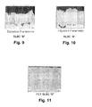
- the baseline sample is illustrated in the micrograph picture of Fig. 9 .
- the deposition rate was adjusted to about 0.53 mils/pass at a combustion ratio (Oxygen/Fuel ratio) of about 0.28 to produce the adjusted test button sample shown in the micrograph picture of Fig. 10 .
- This adjusted test sample was inspected for microstructure properties and satisfied the density requirement of at least about 90% of theoretical, and had a surface roughness of about 452 Ra.
- the sample exhibited a bond coat to substrate tensile strength exceeding 12.0 ksi.
- the same ceramic thermal barrier material was added to the adjusted test sample to produce the test sample shown in the micrograph of Fig. 11 .
- This sample exhibited a ceramic thermal barrier coat to bond coat tensile strength of about 5.7 ksi.
- Table 1 Sample Dep Rate Ra BC Microstructure BC Tensile TBC Tensile (mils/pass) ( ⁇ inch) pass/fail (ksi) (ksi) Sample A 0.68 490 PASS >12 5.1 Sample B 0.53 452 PASS >12 5.7 Bi-layer 6-65 418 PASS >12 5.7
Landscapes
- Chemical & Material Sciences (AREA)
- Engineering & Computer Science (AREA)
- Materials Engineering (AREA)
- Mechanical Engineering (AREA)
- Metallurgy (AREA)
- Organic Chemistry (AREA)
- Chemical Kinetics & Catalysis (AREA)
- Physics & Mathematics (AREA)
- Plasma & Fusion (AREA)
- Inorganic Chemistry (AREA)
- Ceramic Engineering (AREA)
- General Engineering & Computer Science (AREA)
- Coating By Spraying Or Casting (AREA)
- Turbine Rotor Nozzle Sealing (AREA)
- Other Surface Treatments For Metallic Materials (AREA)
Abstract
Description
- The present invention relates generally to protective coatings applied to metal substrates. More specifically, the invention is directed to a single layer bond coat having the benefits of conventional bi-layer bond coats, and to the related method for application of such single layer bond coats.
- Higher operating temperatures for gas turbine engines are continuously sought in order to increase their efficiency. However, as operating temperatures increase, the temperature durability of the engine components must correspondingly increase. Significant advances in high temperature capabilities have been achieved through the formulation of nickel and cobalt-based superalloys, and through the development of oxidation-resistant overlay coatings deposited directly on the surface of the superalloy substrate to form a protective oxide scale during high temperature exposure. Nonetheless, superalloys protected by overlay coatings often do not retain adequate mechanical properties for components located in certain sections of a gas turbine engine, such as the combustor and augmentor. A common solution is to thermally insulate such components in order to minimize their service temperatures. For this purpose, thermal barrier coating (TBC) systems formed on the exposed surfaces of high temperature components have found wide use.
- To be effective, TBC systems must have low thermal conductivity, strongly adhere to the article, and remain adherent throughout many heating and cooling cycles. The latter requirement is particularly demanding due to the different coefficients of thermal expansion between materials having low thermal conductivity and superalloy materials typically used to form turbine engine components. TBC systems capable of satisfying the above requirements generally require a metallic bond coat deposited on the component surface, followed by an adherent thermal barrier ceramic layer that serves to thermally insulate the component. Various ceramic materials have been employed as the thermal barrier layer, particularly zirconia (ZrO2) stabilized by yttria (Y2 O3), magnesia (MgO), ceria (CeO2), scandia (Sc2O3), or another oxide.
- The bond coat is typically formed from an oxidation-resistant aluminum-containing alloy to promote adhesion of the ceramic layer to the component and inhibit oxidation of the underlying superalloy. Examples of prior art bond coats include overlay coatings such as MCrAlY (where M is iron, cobalt and/or nickel), and diffusion coatings such as diffusion aluminide or platinum aluminide, which are oxidation-resistant aluminum-base intermetallics. The bond coat is typically disposed on the substrate by a thermal spray processes, such as vacuum plasma spray (VPS) (also know as low pressure plasma spraying (LPPS)), air plasma spray (APS), and high velocity oxy-fuel (HVOF) spray processes.
- Conventional bond coats are typically applied as a bi-layer construction wherein a fine powder is first deposited on the substrate to form a dense, low oxide layer. Commercially available HVOF systems are typically used to deposit this layer. It is generally recognized that conventional HVOF processes are sensitive to particle size distributions, generally requiring finer particles ranging from -45+10µm. The fine particle layer serves to protect the substrate from oxidation and corrosion, but the low surface roughness of the layer results in inadequate adhesion of the ceramic material layer.
- A coarse powder layer is then deposited over the fine powder layer to achieve a desired degree of surface roughness for adequate adhesion of the ceramic material. APS bond coating techniques are often favored for the coarse powder layer due to lower equipment cost and ease of application and masking. Adhesion of the ceramic material layer to an APS bond coat is promoted by forming the bond coat to have a surface roughness of about 200 microinches (about 5 µm) to about 500 microinches (about 13 µm) Ra (Arithmetic Average Roughness (Ra) as determined from ANSI/ASME Standard B461-1985).
- Although APS-applied bond coats provide better TBC adhesion due to their roughness, the coarse powder layer is generally unsuitable as a protective coating system. The coarse powder layer is relatively porous and prone to oxidation damage.
- Thus, conventional bond coats are applied as a bi-layer in separate processes with separate equipment configurations to achieve the desired characteristics of a dense, low-oxide protective layer, and the surface roughness of a coarse powder layer. This practice, however, requires maintaining both powders in inventory, as well as the different coating systems. The process is time consuming in that it involves set up for two different processes, and can result in rework of coated pieces due to equipment or powder mix-ups.
- Accordingly, the art would benefit from an improved commercially viable process for applying a single layer bond coat from a single powder composition, with the bond coat having the desired properties of conventional bi-layer bond coats.
- Aspects and advantages of the invention will be set forth in part in the following description, or may be obvious from the description, or may be learned through practice of the invention.
- The present invention provides a protective coating system for a metal substrate, and is particularly suited for metal components of a gas turbine engine. The system includes a superalloy metal substrate having a single layer bond coat applied to the substrate. The bond coat is applied in a thermal spray process, for example a high velocity oxy-fuel (HVOF) process, from a homogeneous powder composition that results in a bond coat having properties comparable to bi-layer bond coats. The powder composition has a particle size distribution wherein about 90% of the particles by volume are within a range of about 10 µm to about 100 µm. The particles are distributed relatively uniformly within the range in that the percentage of particles within any 10 µm band within the range does not exceed about 20% by volume, and the percentage of particles within any two adjacent 10 µm bands within the range does not deviate by more than about 8% by volume. The coating system may also encompass a ceramic thermal barrier layer applied to the single layer bond coat, or the bond coat may be the only layer of the protective coating system.
- The present invention also encompasses a method for forming a protective coating system on a metal substrate. The method includes applying a single layer bond coat to a superalloy metal substrate, such as a Ni or Co based superalloy, in a thermal spray process, for example an HVOF process, from a homogeneous powder composition having a particle size distribution such that the resulting bond coat has properties at least comparable to bi-layer bond coats. About 90% by volume of the particles are within a range of about 10 µm to about 100 µm. The percentage of particles within any 10 µm band within the range does not exceed about 20% by volume, and the percentage of particles within any two adjacent 10 µm bands within the range does not deviate by more than about 8% by volume. A single layer bond coat formed in accordance with the present method may have a surface roughness of at least about 300 µinch Ra, a density of at least about 90% of theoretical density; and a bond coat to substrate tensile strength of at least about 6.0 ksi. The bond coat powder composition may include MCrAlY alloy particles, where M is at least one of iron, cobalt, or nickel. In a further refinement of the method, a ceramic thermal barrier layer is applied over the single layer bond coat, with a thermal barrier layer to bond coat tensile strength that exceeds the cohesive strength of the ceramic layer, regardless of the morphology of the ceramic layer. This ceramic barrier layer may be formed from, for example, commercially available yttria stabilized ceramic coating particles.
- These and other embodiments and features of the invention will be described in greater detail in the following description.
- A full and enabling disclosure of the present invention, including the best mode thereof, directed to one of ordinary skill in the art, is set forth in the specification, which makes reference to the appended figures, in which:
-
Fig. 1 is a cross-sectional view of a conventional thermal barrier coat protective system having a bi-layer bond coat; -
Fig. 2 is a cross-sectional view of a single layer bond coat applied to a metal substrate in accordance with aspects of the invention; -
Fig. 3 is a cross-sectional view of a thermal barrier coat system having a single layer bond coat in accordance with aspects of the invention; -
Fig. 4 is a perspective view of a conventional gas turbine blade configuration; -
Fig. 5 is a plot of the particle size distribution profile for various powder compositions; -
Figs. 6 through 8 are micrograph pictures of test samples having a first embodiment of a single layer bond coat in accordance with aspects of the invention; and -
Figs. 9 through 11 are micrograph pictures of test samples having a second embodiment of a single layer bond coat in accordance with aspects of the invention. - Reference now will be made in detail to embodiments of the invention, one or more examples of which are illustrated in the drawings. Each example is provided by way of explanation of the invention, not limitation of the invention. In fact, it will be apparent to those skilled in the art that various modifications and variations can be made in the present invention without departing from the scope of the invention. For instance, features illustrated or described as part of one embodiment, can be used with another embodiment to yield a still further embodiment. Thus, it is intended that the present invention covers such modifications and variations as come within the scope of the appended claims and their equivalents.
- As previously discussed, thermal barrier coating (TBC) systems are often used to improve the efficiency and performance of metal parts which are exposed to high temperatures, such as nozzles, buckets, shrouds, airfoils, and other gas turbine components. The combustion gas temperatures present in conventional gas turbines are maintained as high as possible for operating efficiency, and turbine combustion components and other elements of the engine are usually made of alloys which can resist the high temperature environment, e.g., superalloys, which have an operating temperature limit of about 1000-1150 degrees Celsius. The TBC systems effectively increase the operating temperature of the turbine by maintaining or reducing the surface temperature of the alloys used to form the various engine components.
- The TBC systems are also critical for protecting the surfaces of various turbine components. Referring to
Fig. 1 , mostconventional TBC systems 30 are dual-layer systems that include a ceramic-basedtop layer 38 deposited over a denser, oxidation-resistantbi-layer bond coat 32. The ceramic material is typically a material like zirconia (zirconium oxide), which is usually chemically stabilized with another material such as yttria. Thebond coat 32 is applied to ametal substrate 40 as a bi-layer construction wherein a fine powder is first deposited on the substrate to form a dense,low oxide layer 34. Acoarse powder layer 36 is then deposited over the fine powder layer to achieve a desired degree of surface roughness for adequate adhesion of theceramic material 38. - Referring to
Fig. 2 , the present invention relates to aprotective coating system 50 having an improved, single layer bond coat (SLBC) 54 applied to ametal substrate 40. Although theSLBC 54 will typically form the initial layer in a TBC system, it should be appreciated that abond coat 54 in accordance with the present invention may also be used as a stand-alone protective overlay coating on any manner of metallic substrate, i.e., without a ceramic top layer, as depicted inFig. 2. Fig. 3 depicts aprotective coating system 50 in accordance with the invention that includes aceramic layer 38 applied over theSLBC 54. - Single
layer bond coatings 54 in accordance with the invention may be applied to components of a gas turbine, as discussed above, or used in other environments, such as selected components of diesel or other types of internal combustion engines.Fig. 4 is provided for purposes of illustrating an environment in which the present invention is particularly useful, and depicts a conventional gasturbine blade configuration 10. A plurality of theblades 10 are attached to an annular rotor disk (not shown) in a gas turbine.Blade 10 includes anairfoil 12, having pressure andsuction sides 14, 16, and leading and trailingedges 18 and 20. The lower part of the airfoil terminates with base 22. Base 22 includes a platform 24, in which the airfoil can be rigidly mounted in an upright position, i.e., substantially vertical to thetop surface 25 of the platform. The base further includes adovetail root 26, attached to the underside of the platform, for attachingblade 10 to the rotor. Theairfoil 12 is at least one component that typically requires a thermal barrier coating. - The
SLBC 54 is applied to any manner ofmetal substrate 40 in a thermal spray process from a homogeneous powder composition having a particle size distribution that provides theSLBC 54 with comparable characteristics of a bi-layer bond coat. In particular, theSLBC 54 has the density and low oxide content of a fine powder layer comparable tolayer 34 ofFig. 1 , and the surface roughness of a coarse powder layer comparable tolayer 36 ofFig. 1 . - Referring to the particle size distribution graph of
Fig. 5 , a homogeneous powder composition used in the thermal spray process to apply theSLBC 54 has the particle size characteristics of, for example, graphs C, D, or E in that about 90% of the particles by volume are within a range of about 10 µm to about 100 µm. In addition, the percentage of particles within any 10 µm band within the range does not exceed about 20% by volume, and the percentage of particles within any two adjacent 10 µm bands within the range does not deviate by more than about 8% by volume. For example referring to an ideal distribution graph C, it is seen that the particles within any 10 µm (i.e., 20 to 30 µm band, or 30 to 40 µm band, or 35 to 45 µm band) do not exceed about 13 % by volume of the composition, and such percentage does not deviate across the range. In other words, the percentage of particles within the band of 20 to 30 µm is the same as the percentage of particles within the band of 30 to 40 µm, and so forth. - The graph C in
Fig. 5 is considered "ideal" because of its flat, truncated profile wherein the percentage of particles within the 10 µm bands is the same across the stated range (i.e., range of about 10 µm to about 100 µm). However, this profile may not be economically feasible or otherwise attainable with blends or mixtures of commercially available powders. A more realistic particle size distribution may be reflected by, for example, graph D. This profile has a "bi-modal" aspect in that distinct fine and coarse particle peaks are identifiable, yet the overall profile still satisfies the requirements set forth above. - Graph A in
Fig. 5 illustrates a typical particle size distribution curve for conventional fine particles used to form an initial layer 34 (Fig. 1 ) in conventional TBC systems, and is provided for purposes of comparison with curves for powder compositions in accordance with the present invention . Conventional fine powders have a particle size distribution range of generally about -53+22 µm (d10 percentile of approximately 22 µm; d90 percentile of approximately 53 µm). Commercial HVOF powders are typically in the range of about -45+10 µm. Graph B is a typical particle size distribution curve for coarse powders used to form thesecond layer 36 of conventional bond coats 32 (Fig. 1 ), and is also provided for comparative purposes. These coarse powders have a particle size distribution range of about -100+44 µm (d10 percentile of approximately 44 µm; d90 percentile of approximately 100 µm). - Graph E in
Fig. 5 is provided as an example of another type of powder composition that falls within the scope of the present invention. This graph has a profile that reflects a generally continuously changing profile similar to a bell-curve that still satisfies the requirements set forth above. It should be appreciated that any manner of particle size distribution curve is possible that satisfies the requirements of the present invention, and that the invention is not limited to any particular curve or distribution profile that satisfies the stated requirements. - The
SLBC 54 formed from a powder composition as described above has a surface roughness of at least about 300 µinch Ra (Arithmetic Average Roughness (Ra) as determined from ANSI/ASME Standard B461-1985). In particular embodiments, the surface roughness will be at least about 400 µinch Ra. The rough surface serves to ensure good adhesion between the bond coat and a subsequently applied thermal barrier material. It should be appreciated that the surface roughness value of the SLBC is not an issue when the SLBC is used as the only layer in the protective coating system, i.e., a ceramic thermal barrier material layer is not applied over the SLBC. - Single
layer bond coats 54 according to the present process may be formed having any suitable thickness. Typical bond coats in a bi-layer coating system are typically within a range of about 250 µm to about 500 µm. ASLBC 54 in accordance with the present invention may not need to be as thick as these conventional bond coats, and may have a thickness less than conventional bond coats, for example, of about 125µm, or 200 µm. It is believed that a 200 µm SLBC will produce the equivalent life of a 350 µm bi-layer bond coat. - The
SLBC 54 will also have a density of at least about 90% of theoretical density, and in particular embodiments, at least about 95% of theoretical density. - The
SLBC 54 also has a bond coat to substrate tensile strength of at least about 6.0 ksi, and in particular embodiments, at least about 12.0 ksi. - The
SLBC 54 is applied in a thermal spray process having a particle velocity of at least about 400 m/s. Various techniques are available for measuring particle velocity downstream from the plasma gun exit, using a variety of sensor systems. As a non-limiting example, measuring systems for determining particle velocity and particle velocity distribution are described inU.S. Pat. No. 6,862,536 (Rosin ). One example of an on-line particle monitoring and measurement device which is commercially available is the DPV-2000 system, available from Tecnar Automation Ltd, Montreal, Canada (http://www.tecnar.com/). - Although it is generally held that conventional high velocity oxy-fuel (HVOF) thermal spray systems are sensitive to particle size distributions (generally requiring finer particles ranging from -45+10 µm), the present inventors have found that such HVOF systems may be used for the protective coating system and methodology of the present invention. By carefully monitoring and adjusting the HVOF thermal spray parameters, a single layer bond coat is achievable from a powder composition as described herein that is dense and relatively oxide-free, yet has the surface roughness and porosity required for good adhesion of a ceramic material layer. For example, the combustion ratio in a HVOF process for purposes of the present invention should be less than about 0.29, and desirably within a range of about 0.27 to about 0.29. This combustion ratio with the powder composition discussed above yields satisfactory deposition rates.
- With respect to deposition rates, the relationship of pounds of powder per mil of coating per square unit of area coated is an objective standard. A deposit efficiency is desirable that produces a satisfactory coating without excess wastage of powder. A baseline parameter may first be established, for example 0.13 lbs. per mil of coating per square foot of surface coating. The combustion ratio may then be adjusted from a low baseline value of, for example, 0.235, until the plume temperature reaches a limit indicative of excessive oxide in past experience with similar powder chemistries. With the increased combustion ratio, an increased deposit rate efficiency results of about .08 lbs. of powder per square foot of area coated to a thickness of about 1 mil. A further increase of the combustion ratio so that even less powder is required may lead to unacceptable levels of oxide in the coating. A deposition rate range of about 0.15 to about 0.08 lbs/mil/ft2 at a combustion ratio that does not produce unacceptable oxides in the coating may be desired for purposes of the
SLBC 54. - Examples of the other steps and process parameters that may be adjusted to achieve a
SLBC 54 in accordance with the present invention include: cleaning of the surface prior to deposition; grit blasting to remove oxides; substrate temperature; other plasma spray parameters such as spray distance (gun-to-substrate); selection of the number of spray-passes, powder feed rate, torch power, plasma gas selection; angle-of-deposition, post-treatment of the applied coating; and the like. - Another suitable thermal spray process is a high velocity air plasma spray (HV-APS) process wherein particle velocity is maintained in the range of about 300 m/s to about 700 m/s. In some specific embodiments, the velocity is at least about 450 m/s, and may be about 600 m/s. These particle velocities are substantially greater than the typical velocities used in conventional APS systems (in the range of about 150-250 m/s). For a HV-APS system, a conventional APS system can be modified to effectively increase the plasma velocity and hence, the particle velocity. In general, modification of the APS system in this instance involves the selection of different configurations of anode nozzles which fit into the plasma spray guns, and commercial APS guns equipped with high-velocity anode nozzles can be employed to carry out the high velocity air plasma spray (HV-APS) process. Non-limiting examples include the 7 MB (or 9 MB, or 3MB) plasma spray gun equipped with the 704 high velocity nozzle, available from Sulzer Metco, Inc. Another example is the SG100 plasma spray gun, operated in the "Mach 2" mode, available from Praxair Surface Technologies, Inc. These conventional APS gun systems may be operated in a power range of, for example, 30 -50 KW.
- The powder composition for the
SLBC 54 may comprise MCrAlY alloy particles, where M is at least one of iron, cobalt, or nickel. - The resulting
SLBC 54 has a density of at least 90% of theoretical density, and more particularly about 95% density. These densities reflect a decreased oxide content in the bond coating that greatly increases the effective TBC life and the substrate life against oxidation. Decreased oxide content in the bond coat (as reflected by an increased density) inhibits detrimental growth of thermally grown oxide (TGO) at the interface of the bond coat and ceramic coat during service of the component. It is generally accepted that TGO accelerates TBC failures, such as cracking, delamination, and spalling. - Referring to
Fig. 3 , theprotective coating system 50 of the present invention may also encompass application of athermal barrier material 38 applied over thebond coat 54, which may include any of various known ceramic materials, such as zirconia (ZrO2) stabilized by yttria (Y2 O3), magnesia (MgO), ceria (CeO2), scandia (Sc2O3), or another oxide. Commercially available yttria stabilized ceramic coating particles may be used for the TBC material, for example, Sulzer Metco 240NS 8 wt % yttria stabilized zirconia powder having a particle size distribution range of about -11+125 µm (d10 percentile of approximately 11 µm; d90 percentile of approximately 125 µm), or Sulzer Metco 240NA powder having a particle size distribution range of about -97+25 µm. Theceramic barrier material 38 may be deposited by any suitable known technique, such as by physical vapor deposition (PVD) techniques, particularly electron beam physical vapor deposition (EBPVD), or conventional APS techniques. Desirably, thecoating system 50 produces athermal barrier coat 38 tobond coat 54 tensile strength that exceeds the cohesive strength of the ceramic layer, regardless of the morphology of the ceramic layer. For example, for a dense vertically cracked ceramic layer, a tensile strength of at least about 4.0 ksi., and at least about 5.0 ksi. in certain embodiments, may be desired. The thickness of theceramic barrier coating 38 will depend on the end use of the part being coated. The thickness is usually in the range of about 100 microns to about 2500 microns. In some specific embodiments for end uses such as airfoil components, the thickness is often in the range of about 125 microns to about 750 microns. - Gas turbine component parts are exemplified as the "metal substrate" in this patent specification. It should be appreciated, however, that other types of components could serve as metal substrates for bond coats in accordance with the invention. As one example, the substrate may be the piston head of a diesel engine, or other automotive parts. It should be readily appreciated that the invention is not limited to any particular type of metal substrate or component.
- The following examples are merely illustrative, and should not be construed to be any sort of limitation on the scope of the claimed invention.
- A first (Sample A) bi-modal MCrAlY powder composition having a particle size distribution generally in accordance with Graph D of
Fig. 5 was evaluated for microstructure properties, surface roughness, and deposit efficiency as compared to a conventional bi-layer bond coat. An initial bond coat test button sample was thermally sprayed in a HVOF process with a Sulzer Metco DJ 2600 system. This baseline sample is illustrated in the micrograph picture ofFig. 6 . The spray process parameters were adjusted to optimize deposit efficiency, as discussed above. In particular, baseline spray parameters included a combustion ratio of about .235 and a low deposit rate, which produced an inefficient process wherein essentially more of the powder was landing on the floor of the chamber than was adhering to the component. Using process monitoring diagnostics, the combustion ratio was increased until the plume temperature reached a limit indicative of excessive oxide in past experience with similar powder chemistries. This new parameter produced a combustion ratio with a significant improvement in efficiency of powder sticking to the component. The deposition rate was adjusted to between about 0.08 to about 0.1 lbs/mil/ft2 at a combustion ratio (Oxygen/Fuel ratio) of about 0.28 (resulting in a deposition rate of about 0.68 mils/pass), to produce the adjusted test button sample shown in the micrograph picture ofFig. 7 . This adjusted test sample was inspected for microstructure properties and satisfied the density requirement of at least about 90% of theoretical, and had a measured surface roughness of about 490 Ra. The sample exhibited a bond coat to substrate tensile strength exceeding 12.0 ksi. A ceramic thermal barrier coat was added to the bond coat ofFig. 7 in an APS process from a yttria stabilized ceramic powder to produce the test sample shown in the micrograph ofFig. 8 . This test sample exhibited a ceramic thermal barrier coat to bond coat tensile strength of about 5.1 ksi. - A second (Sample B) bi-modal powder composition having a particle size distribution generally in accordance with Graph D of
Fig. 5 was used to produce test buttons as described above with respect to Sample A. The baseline sample is illustrated in the micrograph picture ofFig. 9 . The deposition rate was adjusted to about 0.53 mils/pass at a combustion ratio (Oxygen/Fuel ratio) of about 0.28 to produce the adjusted test button sample shown in the micrograph picture ofFig. 10 . This adjusted test sample was inspected for microstructure properties and satisfied the density requirement of at least about 90% of theoretical, and had a surface roughness of about 452 Ra. The sample exhibited a bond coat to substrate tensile strength exceeding 12.0 ksi. The same ceramic thermal barrier material was added to the adjusted test sample to produce the test sample shown in the micrograph ofFig. 11 . This sample exhibited a ceramic thermal barrier coat to bond coat tensile strength of about 5.7 ksi. - The below table (Table 1) summarizes the results discussed above for the Sample A and Sample B SLBC systems as compared to a conventional bi-layer bond coat:
Table 1 Sample Dep Rate Ra BC
MicrostructureBC
TensileTBC
Tensile(mils/pass) (µinch) pass/fail (ksi) (ksi) Sample A 0.68 490 PASS >12 5.1 Sample B 0.53 452 PASS >12 5.7 Bi-layer 6-65 418 PASS >12 5.7 - The samples of
Figs. 8 and11 were then tested for TBC endurance in various furnace cycle tests (FCT) by raising the sample temperature to 1900° F (first test) and 2000° F (second test) in about 10 minutes in a bottom-loading CM furnace, followed by a hold period of 0.75 and 20 hrs, respectively, and then cooling to less than 500° F in about 9 minutes. The cycle is repeated until more than 20% of the surface area of the ceramic coating spalls from the underlying surface. The approximate hours to failure for the Sample A, Sample B, and comparative Bi-layer sample are provided in the below table (Table 2):Table 2: FCT Approximate Hours to failure Sample 1900° F 2000° F 0.75 hr 20.0 hr 0.75 hr. 20.0 hr Sample A 1800 2750 240 1400 Sample B 2300 5700 400 1350 Bi-layer 800 5700 400 1300 - While the present subject matter has been described in detail with respect to specific exemplary embodiments and methods thereof, it will be appreciated that those skilled in the art, upon attaining an understanding of the foregoing may readily produce alterations to, variations of, and equivalents to such embodiments. Accordingly, the scope of the present disclosure is by way of example rather than by way of limitation, and the subject disclosure does not preclude inclusion of such modifications, variations and/or additions to the present subject matter as would be readily apparent to one of ordinary skill in the art.
Claims (15)
- A protective coating system for metal components, comprising:a superalloy metal substrate;a single layer bond coat applied to the superalloy metal substrate, said bond coat applied in a thermal spray process from a homogeneous powder composition having a particle size distribution wherein:about 90% of the particles by volume are within a range of about 10 µm to about 100 µm;the percentage of particles within any 10 µm band within the range does not exceed about 20% by volume; andthe percentage of particles within any two adjacent 10 µm bands within the range does not deviate by more than about 8% by volume.
- The system in claim 1, wherein said bond coat comprises the following additional characteristics:a surface roughness of at least about 300 µinch Ra;a density of at least about 90% of theoretical density; anda bond coat to substrate tensile strength of at least about 6.0 ksi.
- The system as in claim 1 or claim 2, wherein said single layer bond coat is applied in one of a high velocity oxy-fuel (HVOF) thermal spray process or a high velocity air plasma spray (HV-APS) thermal spray process.
- The system as in any preceding claim, further comprising a ceramic thermal barrier coat (TBC) applied over said single layer bond coat, and a TBC to bond coat tensile strength that exceeds the cohesive strength of the ceramic thermal barrier coat material.
- A method for forming a protective coating system on a metal substrate, said method comprising:applying a single layer bond coat to a superalloy metal substrate in a thermal spray process from a homogeneous powder composition having a particle size distribution range wherein:about 90% by volume of the particles are within a range of about 10 µm to about 100 µm;the percentage of particles within any 10 µm band within the range does not exceed about 20% by volume; andthe percentage of particles within any two adjacent 10 µm bands within the range does not deviate by more than about 8% by volume.
- The method as in claim 5, wherein the single layer bond coat is applied to have the following additional characteristics:a surface roughness of at least about 300 µinch Ra;a density of at least about 90% of theoretical density; anda bond coat to substrate tensile strength of at least about 6.0 ksi.
- The method as in claim 5 or system as in claim 2, wherein the single layer bond coat is applied to have the following additional characteristics:a surface roughness of at least about 400 µinch Ra;a density of at least about 95% of theoretical density; anda bond coat to substrate tensile strength of at least about 12.0 ksi.
- The method as in any of claims 5 to 7, wherein the single layer bond coat is applied in the thermal spray process having a particle velocity of at least about 300 m/s.
- The method as in any one of claims 5 to 8, further comprising applying a ceramic thermal barrier coat (TBC) over the single layer bond coat, with a TBC to bond coat tensile strength that exceeds the cohesive strength of the ceramic thermal barrier coat material.
- The method as in claim 9, wherein the TBC to bond coat tensile strength is at least about 4.0 ksi.
- The method as in any of claims to 5 to 10 or system of claims 1 to 4, wherein the bond coat powder composition comprises MCrAlY alloy particles, where M is at least one of iron, cobalt, or nickel.
- The method as in any one of claims 5 to 11, wherein the single layer bond coat is applied at a deposition rate of at least of about 0.15 to about 0.08 lbs/mil/ft2
- The method as in any one of claims 5 to 12, wherein the single layer bond coat is applied in a high velocity oxy-fuel (HVOF) thermal spray process at a combustion ratio that is less than about 0.29.
- The method as in claim 13, wherein the combustion ratio is within a range of about 0.27 to about 0.29.
- The method as in any one of claims 5 to 14 or system as in any one of claims 1 to 4, wherein the metal substrate is a component of a gas turbine.
Applications Claiming Priority (1)
| Application Number | Priority Date | Filing Date | Title |
|---|---|---|---|
| US12/570,011 US8053089B2 (en) | 2009-09-30 | 2009-09-30 | Single layer bond coat and method of application |
Publications (2)
| Publication Number | Publication Date |
|---|---|
| EP2305852A1 true EP2305852A1 (en) | 2011-04-06 |
| EP2305852B1 EP2305852B1 (en) | 2013-04-17 |
Family
ID=43259757
Family Applications (1)
| Application Number | Title | Priority Date | Filing Date |
|---|---|---|---|
| EP10179700.9A Revoked EP2305852B1 (en) | 2009-09-30 | 2010-09-24 | Method for the Production of a single layer bond coat. |
Country Status (4)
| Country | Link |
|---|---|
| US (1) | US8053089B2 (en) |
| EP (1) | EP2305852B1 (en) |
| JP (1) | JP5762709B2 (en) |
| CN (1) | CN102031478B (en) |
Cited By (2)
| Publication number | Priority date | Publication date | Assignee | Title |
|---|---|---|---|---|
| EP3034648A1 (en) * | 2014-12-16 | 2016-06-22 | United Technologies Corporation | Methods for coating gas turbine engine components |
| EP3461925A1 (en) * | 2017-09-29 | 2019-04-03 | General Electric Technology GmbH | Method for manufacturing a coating |
Families Citing this family (16)
| Publication number | Priority date | Publication date | Assignee | Title |
|---|---|---|---|---|
| US9822437B2 (en) * | 2009-12-17 | 2017-11-21 | Mitsubishi Hitachi Power Systems, Ltd. | Process for producing thermal barrier coating |
| JP6054137B2 (en) * | 2012-10-24 | 2016-12-27 | 三菱日立パワーシステムズ株式会社 | High temperature member for gas turbine having thermal barrier coating |
| US9828934B2 (en) * | 2013-07-09 | 2017-11-28 | Nissan Motor Co., Ltd. | Iron-based sprayed coating, cylinder block for internal combustion engine using same, and sliding mechanism for internal combustion engine |
| US9243511B2 (en) | 2014-02-25 | 2016-01-26 | Siemens Aktiengesellschaft | Turbine abradable layer with zig zag groove pattern |
| RU2016134446A (en) | 2014-02-25 | 2018-03-29 | Сименс Акциенгезелльшафт | THERMAL BARRIER COATING OF A TURBINE COMPONENT WITH MATERIAL PROPERTIES VARIABLE DEPTH |
| US9151175B2 (en) | 2014-02-25 | 2015-10-06 | Siemens Aktiengesellschaft | Turbine abradable layer with progressive wear zone multi level ridge arrays |
| US8939706B1 (en) | 2014-02-25 | 2015-01-27 | Siemens Energy, Inc. | Turbine abradable layer with progressive wear zone having a frangible or pixelated nib surface |
| US10190435B2 (en) | 2015-02-18 | 2019-01-29 | Siemens Aktiengesellschaft | Turbine shroud with abradable layer having ridges with holes |
| EP3259452A2 (en) | 2015-02-18 | 2017-12-27 | Siemens Aktiengesellschaft | Forming cooling passages in combustion turbine superalloy castings |
| JP6488810B2 (en) * | 2015-03-24 | 2019-03-27 | いすゞ自動車株式会社 | Method for forming porous sprayed film |
| US10578050B2 (en) | 2015-11-20 | 2020-03-03 | Tenneco Inc. | Thermally insulated steel piston crown and method of making using a ceramic coating |
| US10519854B2 (en) | 2015-11-20 | 2019-12-31 | Tenneco Inc. | Thermally insulated engine components and method of making using a ceramic coating |
| US10273902B2 (en) | 2016-02-22 | 2019-04-30 | Tenneco Inc. | Insulation layer on steel pistons without gallery |
| US10859033B2 (en) | 2016-05-19 | 2020-12-08 | Tenneco Inc. | Piston having an undercrown surface with insulating coating and method of manufacture thereof |
| EP3957827B1 (en) | 2020-08-18 | 2024-10-02 | Ansaldo Energia Switzerland AG | A coating system for a component of a gas turbine engine |
| WO2025113846A1 (en) * | 2023-11-27 | 2025-06-05 | Siemens Energy Global GmbH & Co. KG | Bilayer thermal barrier coating with improved bond between the ceramic layers |
Citations (4)
| Publication number | Priority date | Publication date | Assignee | Title |
|---|---|---|---|---|
| US5817372A (en) * | 1997-09-23 | 1998-10-06 | General Electric Co. | Process for depositing a bond coat for a thermal barrier coating system |
| WO1999043861A1 (en) * | 1998-02-28 | 1999-09-02 | General Electric Company | Multilayer bond coat for a thermal barrier coating system and process therefor |
| US6862536B2 (en) | 2000-07-19 | 2005-03-01 | Tr-Tech Int. Oy | Measuring system and a method for measuring particle velocity and/or particle velocity distribution and/or particle size distribution |
| EP1939317A2 (en) * | 2006-12-15 | 2008-07-02 | United Technologies Corporation | Thermal barrier coating |
Family Cites Families (12)
| Publication number | Priority date | Publication date | Assignee | Title |
|---|---|---|---|---|
| US5518178A (en) * | 1994-03-02 | 1996-05-21 | Sermatech International Inc. | Thermal spray nozzle method for producing rough thermal spray coatings and coatings produced |
| JPH08311635A (en) * | 1995-05-12 | 1996-11-26 | Sumitomo Metal Mining Co Ltd | High speed powder type flame spraying tungsten carbide cermet powder |
| JPH09316622A (en) * | 1996-05-28 | 1997-12-09 | Toshiba Corp | Gas turbine member and thermal barrier coating method thereof |
| US5817371A (en) | 1996-12-23 | 1998-10-06 | General Electric Company | Thermal barrier coating system having an air plasma sprayed bond coat incorporating a metal diffusion, and method therefor |
| US6096381A (en) * | 1997-10-27 | 2000-08-01 | General Electric Company | Process for densifying and promoting inter-particle bonding of a bond coat for a thermal barrier coating |
| US6242050B1 (en) * | 1998-11-24 | 2001-06-05 | General Electric Company | Method for producing a roughened bond coat using a slurry |
| US6136453A (en) * | 1998-11-24 | 2000-10-24 | General Electric Company | Roughened bond coat for a thermal barrier coating system and method for producing |
| US6254997B1 (en) * | 1998-12-16 | 2001-07-03 | General Electric Company | Article with metallic surface layer for heat transfer augmentation and method for making |
| US6706319B2 (en) * | 2001-12-05 | 2004-03-16 | Siemens Westinghouse Power Corporation | Mixed powder deposition of components for wear, erosion and abrasion resistant applications |
| US7150921B2 (en) | 2004-05-18 | 2006-12-19 | General Electric Company | Bi-layer HVOF coating with controlled porosity for use in thermal barrier coatings |
| US7540156B2 (en) | 2005-11-21 | 2009-06-02 | General Electric Company | Combustion liner for gas turbine formed of cast nickel-based superalloy |
| US20090162670A1 (en) | 2007-12-20 | 2009-06-25 | General Electric Company | Method for applying ceramic coatings to smooth surfaces by air plasma spray techniques, and related articles |
-
2009
- 2009-09-30 US US12/570,011 patent/US8053089B2/en active Active
-
2010
- 2010-09-24 EP EP10179700.9A patent/EP2305852B1/en not_active Revoked
- 2010-09-28 JP JP2010216274A patent/JP5762709B2/en active Active
- 2010-09-30 CN CN201010506389.9A patent/CN102031478B/en active Active
Patent Citations (4)
| Publication number | Priority date | Publication date | Assignee | Title |
|---|---|---|---|---|
| US5817372A (en) * | 1997-09-23 | 1998-10-06 | General Electric Co. | Process for depositing a bond coat for a thermal barrier coating system |
| WO1999043861A1 (en) * | 1998-02-28 | 1999-09-02 | General Electric Company | Multilayer bond coat for a thermal barrier coating system and process therefor |
| US6862536B2 (en) | 2000-07-19 | 2005-03-01 | Tr-Tech Int. Oy | Measuring system and a method for measuring particle velocity and/or particle velocity distribution and/or particle size distribution |
| EP1939317A2 (en) * | 2006-12-15 | 2008-07-02 | United Technologies Corporation | Thermal barrier coating |
Cited By (2)
| Publication number | Priority date | Publication date | Assignee | Title |
|---|---|---|---|---|
| EP3034648A1 (en) * | 2014-12-16 | 2016-06-22 | United Technologies Corporation | Methods for coating gas turbine engine components |
| EP3461925A1 (en) * | 2017-09-29 | 2019-04-03 | General Electric Technology GmbH | Method for manufacturing a coating |
Also Published As
| Publication number | Publication date |
|---|---|
| US20110076413A1 (en) | 2011-03-31 |
| JP5762709B2 (en) | 2015-08-12 |
| EP2305852B1 (en) | 2013-04-17 |
| US8053089B2 (en) | 2011-11-08 |
| CN102031478B (en) | 2015-05-27 |
| CN102031478A (en) | 2011-04-27 |
| JP2011074494A (en) | 2011-04-14 |
Similar Documents
| Publication | Publication Date | Title |
|---|---|---|
| EP2305852B1 (en) | Method for the Production of a single layer bond coat. | |
| EP0909831B1 (en) | Process for depositing a bond coat for a thermal barrier coating system | |
| US20110048017A1 (en) | Method of depositing protective coatings on turbine combustion components | |
| EP1076727B1 (en) | Multilayer bond coat for a thermal barrier coating system and process therefor | |
| US7150921B2 (en) | Bi-layer HVOF coating with controlled porosity for use in thermal barrier coatings | |
| EP1939316A1 (en) | Thermal barrier coating system and method for coating a component | |
| US20090162670A1 (en) | Method for applying ceramic coatings to smooth surfaces by air plasma spray techniques, and related articles | |
| US6096381A (en) | Process for densifying and promoting inter-particle bonding of a bond coat for a thermal barrier coating | |
| EP1829984B1 (en) | Process for making a high density thermal barrier coating | |
| EP1939317A2 (en) | Thermal barrier coating | |
| US6352788B1 (en) | Thermal barrier coating | |
| Wang et al. | Commercial thermal barrier coatings with a double-layer bond coat on turbine vanes and the process repeatability | |
| US6274201B1 (en) | Protective coatings for metal-based substrates, and related processes | |
| US20080057213A1 (en) | Thermal barrier coating system and process therefor | |
| EP0969117A2 (en) | Method of forming a thermal barrier coating system | |
| EP1627862A1 (en) | Ceramic compositions for thermal barrier coatings with improved mechanical properties | |
| WO2014126633A2 (en) | Spallation-resistant thermal barrier coating | |
| WO2015053947A1 (en) | Thermal barrier coating with improved adhesion | |
| Parlakyigit et al. | Effects of microstructural transformation in TBCs consisting of NiCrAlY metallic bond coat and YSZ ceramic top coat after oxidation at 900° C | |
| Knight et al. | Influence of bondcoat surface characteristics on the performance of TBC systems | |
| Feuerstein et al. | Thermal barrier coating systems for gas turbine engines by thermal spray and EBPVD-A technical and economic comparison | |
| WO2026024701A1 (en) | Metallic Bond Coat with Enhanced TBC Spallation Resistance | |
| EP3705597A1 (en) | Thermal barrier coating with improved adhesion | |
| Feuerstein et al. | Praxair Surface Technologies, Inc. Indianapolis, Indiana, USA | |
| Zhu et al. | A Comparison of Thermal Shock Behavior between APS and Low-Energy VLPPS ZrO2-7% Y2O3 Thermal Barrier Coatings |
Legal Events
| Date | Code | Title | Description |
|---|---|---|---|
| PUAI | Public reference made under article 153(3) epc to a published international application that has entered the european phase |
Free format text: ORIGINAL CODE: 0009012 |
|
| AK | Designated contracting states |
Kind code of ref document: A1 Designated state(s): AL AT BE BG CH CY CZ DE DK EE ES FI FR GB GR HR HU IE IS IT LI LT LU LV MC MK MT NL NO PL PT RO SE SI SK SM TR |
|
| AX | Request for extension of the european patent |
Extension state: BA ME RS |
|
| 17P | Request for examination filed |
Effective date: 20111006 |
|
| GRAP | Despatch of communication of intention to grant a patent |
Free format text: ORIGINAL CODE: EPIDOSNIGR1 |
|
| GRAS | Grant fee paid |
Free format text: ORIGINAL CODE: EPIDOSNIGR3 |
|
| GRAA | (expected) grant |
Free format text: ORIGINAL CODE: 0009210 |
|
| AK | Designated contracting states |
Kind code of ref document: B1 Designated state(s): AL AT BE BG CH CY CZ DE DK EE ES FI FR GB GR HR HU IE IS IT LI LT LU LV MC MK MT NL NO PL PT RO SE SI SK SM TR |
|
| REG | Reference to a national code |
Ref country code: GB Ref legal event code: FG4D |
|
| REG | Reference to a national code |
Ref country code: CH Ref legal event code: EP |
|
| REG | Reference to a national code |
Ref country code: IE Ref legal event code: FG4D |
|
| REG | Reference to a national code |
Ref country code: AT Ref legal event code: REF Ref document number: 607369 Country of ref document: AT Kind code of ref document: T Effective date: 20130515 |
|
| REG | Reference to a national code |
Ref country code: DE Ref legal event code: R096 Ref document number: 602010006208 Country of ref document: DE Effective date: 20130613 |
|
| REG | Reference to a national code |
Ref country code: AT Ref legal event code: MK05 Ref document number: 607369 Country of ref document: AT Kind code of ref document: T Effective date: 20130417 |
|
| REG | Reference to a national code |
Ref country code: LT Ref legal event code: MG4D |
|
| REG | Reference to a national code |
Ref country code: NL Ref legal event code: VDEP Effective date: 20130417 |
|
| PG25 | Lapsed in a contracting state [announced via postgrant information from national office to epo] |
Ref country code: SI Free format text: LAPSE BECAUSE OF FAILURE TO SUBMIT A TRANSLATION OF THE DESCRIPTION OR TO PAY THE FEE WITHIN THE PRESCRIBED TIME-LIMIT Effective date: 20130417 Ref country code: FI Free format text: LAPSE BECAUSE OF FAILURE TO SUBMIT A TRANSLATION OF THE DESCRIPTION OR TO PAY THE FEE WITHIN THE PRESCRIBED TIME-LIMIT Effective date: 20130417 Ref country code: IS Free format text: LAPSE BECAUSE OF FAILURE TO SUBMIT A TRANSLATION OF THE DESCRIPTION OR TO PAY THE FEE WITHIN THE PRESCRIBED TIME-LIMIT Effective date: 20130817 Ref country code: ES Free format text: LAPSE BECAUSE OF FAILURE TO SUBMIT A TRANSLATION OF THE DESCRIPTION OR TO PAY THE FEE WITHIN THE PRESCRIBED TIME-LIMIT Effective date: 20130728 Ref country code: GR Free format text: LAPSE BECAUSE OF FAILURE TO SUBMIT A TRANSLATION OF THE DESCRIPTION OR TO PAY THE FEE WITHIN THE PRESCRIBED TIME-LIMIT Effective date: 20130718 Ref country code: NO Free format text: LAPSE BECAUSE OF FAILURE TO SUBMIT A TRANSLATION OF THE DESCRIPTION OR TO PAY THE FEE WITHIN THE PRESCRIBED TIME-LIMIT Effective date: 20130717 Ref country code: SE Free format text: LAPSE BECAUSE OF FAILURE TO SUBMIT A TRANSLATION OF THE DESCRIPTION OR TO PAY THE FEE WITHIN THE PRESCRIBED TIME-LIMIT Effective date: 20130417 Ref country code: BE Free format text: LAPSE BECAUSE OF FAILURE TO SUBMIT A TRANSLATION OF THE DESCRIPTION OR TO PAY THE FEE WITHIN THE PRESCRIBED TIME-LIMIT Effective date: 20130417 Ref country code: LT Free format text: LAPSE BECAUSE OF FAILURE TO SUBMIT A TRANSLATION OF THE DESCRIPTION OR TO PAY THE FEE WITHIN THE PRESCRIBED TIME-LIMIT Effective date: 20130417 Ref country code: AT Free format text: LAPSE BECAUSE OF FAILURE TO SUBMIT A TRANSLATION OF THE DESCRIPTION OR TO PAY THE FEE WITHIN THE PRESCRIBED TIME-LIMIT Effective date: 20130417 Ref country code: PT Free format text: LAPSE BECAUSE OF FAILURE TO SUBMIT A TRANSLATION OF THE DESCRIPTION OR TO PAY THE FEE WITHIN THE PRESCRIBED TIME-LIMIT Effective date: 20130819 |
|
| PLBI | Opposition filed |
Free format text: ORIGINAL CODE: 0009260 |
|
| PG25 | Lapsed in a contracting state [announced via postgrant information from national office to epo] |
Ref country code: PL Free format text: LAPSE BECAUSE OF FAILURE TO SUBMIT A TRANSLATION OF THE DESCRIPTION OR TO PAY THE FEE WITHIN THE PRESCRIBED TIME-LIMIT Effective date: 20130417 Ref country code: LV Free format text: LAPSE BECAUSE OF FAILURE TO SUBMIT A TRANSLATION OF THE DESCRIPTION OR TO PAY THE FEE WITHIN THE PRESCRIBED TIME-LIMIT Effective date: 20130417 Ref country code: HR Free format text: LAPSE BECAUSE OF FAILURE TO SUBMIT A TRANSLATION OF THE DESCRIPTION OR TO PAY THE FEE WITHIN THE PRESCRIBED TIME-LIMIT Effective date: 20130417 Ref country code: BG Free format text: LAPSE BECAUSE OF FAILURE TO SUBMIT A TRANSLATION OF THE DESCRIPTION OR TO PAY THE FEE WITHIN THE PRESCRIBED TIME-LIMIT Effective date: 20130717 Ref country code: CY Free format text: LAPSE BECAUSE OF FAILURE TO SUBMIT A TRANSLATION OF THE DESCRIPTION OR TO PAY THE FEE WITHIN THE PRESCRIBED TIME-LIMIT Effective date: 20130417 |
|
| 26 | Opposition filed |
Opponent name: SIEMENS AKTIENGESELLSCHAFT Effective date: 20131114 |
|
| PG25 | Lapsed in a contracting state [announced via postgrant information from national office to epo] |
Ref country code: CZ Free format text: LAPSE BECAUSE OF FAILURE TO SUBMIT A TRANSLATION OF THE DESCRIPTION OR TO PAY THE FEE WITHIN THE PRESCRIBED TIME-LIMIT Effective date: 20130417 Ref country code: DK Free format text: LAPSE BECAUSE OF FAILURE TO SUBMIT A TRANSLATION OF THE DESCRIPTION OR TO PAY THE FEE WITHIN THE PRESCRIBED TIME-LIMIT Effective date: 20130417 Ref country code: EE Free format text: LAPSE BECAUSE OF FAILURE TO SUBMIT A TRANSLATION OF THE DESCRIPTION OR TO PAY THE FEE WITHIN THE PRESCRIBED TIME-LIMIT Effective date: 20130417 Ref country code: SK Free format text: LAPSE BECAUSE OF FAILURE TO SUBMIT A TRANSLATION OF THE DESCRIPTION OR TO PAY THE FEE WITHIN THE PRESCRIBED TIME-LIMIT Effective date: 20130417 |
|
| REG | Reference to a national code |
Ref country code: DE Ref legal event code: R026 Ref document number: 602010006208 Country of ref document: DE Effective date: 20131114 |
|
| PLAX | Notice of opposition and request to file observation + time limit sent |
Free format text: ORIGINAL CODE: EPIDOSNOBS2 |
|
| PG25 | Lapsed in a contracting state [announced via postgrant information from national office to epo] |
Ref country code: RO Free format text: LAPSE BECAUSE OF FAILURE TO SUBMIT A TRANSLATION OF THE DESCRIPTION OR TO PAY THE FEE WITHIN THE PRESCRIBED TIME-LIMIT Effective date: 20130417 Ref country code: IT Free format text: LAPSE BECAUSE OF FAILURE TO SUBMIT A TRANSLATION OF THE DESCRIPTION OR TO PAY THE FEE WITHIN THE PRESCRIBED TIME-LIMIT Effective date: 20130417 Ref country code: NL Free format text: LAPSE BECAUSE OF FAILURE TO SUBMIT A TRANSLATION OF THE DESCRIPTION OR TO PAY THE FEE WITHIN THE PRESCRIBED TIME-LIMIT Effective date: 20130417 |
|
| REG | Reference to a national code |
Ref country code: HU Ref legal event code: AG4A Ref document number: E018721 Country of ref document: HU |
|
| PG25 | Lapsed in a contracting state [announced via postgrant information from national office to epo] |
Ref country code: MC Free format text: LAPSE BECAUSE OF FAILURE TO SUBMIT A TRANSLATION OF THE DESCRIPTION OR TO PAY THE FEE WITHIN THE PRESCRIBED TIME-LIMIT Effective date: 20130417 |
|
| REG | Reference to a national code |
Ref country code: DE Ref legal event code: R119 Ref document number: 602010006208 Country of ref document: DE Effective date: 20140401 |
|
| PLAF | Information modified related to communication of a notice of opposition and request to file observations + time limit |
Free format text: ORIGINAL CODE: EPIDOSCOBS2 |
|
| REG | Reference to a national code |
Ref country code: FR Ref legal event code: ST Effective date: 20140530 |
|
| REG | Reference to a national code |
Ref country code: IE Ref legal event code: MM4A |
|
| PG25 | Lapsed in a contracting state [announced via postgrant information from national office to epo] |
Ref country code: IE Free format text: LAPSE BECAUSE OF NON-PAYMENT OF DUE FEES Effective date: 20130924 |
|
| PG25 | Lapsed in a contracting state [announced via postgrant information from national office to epo] |
Ref country code: FR Free format text: LAPSE BECAUSE OF NON-PAYMENT OF DUE FEES Effective date: 20130930 Ref country code: DE Free format text: LAPSE BECAUSE OF NON-PAYMENT OF DUE FEES Effective date: 20140401 |
|
| PLBB | Reply of patent proprietor to notice(s) of opposition received |
Free format text: ORIGINAL CODE: EPIDOSNOBS3 |
|
| PLAB | Opposition data, opponent's data or that of the opponent's representative modified |
Free format text: ORIGINAL CODE: 0009299OPPO |
|
| R26 | Opposition filed (corrected) |
Opponent name: SIEMENS AKTIENGESELLSCHAFT Effective date: 20131114 |
|
| REG | Reference to a national code |
Ref country code: CH Ref legal event code: PL |
|
| PG25 | Lapsed in a contracting state [announced via postgrant information from national office to epo] |
Ref country code: SM Free format text: LAPSE BECAUSE OF FAILURE TO SUBMIT A TRANSLATION OF THE DESCRIPTION OR TO PAY THE FEE WITHIN THE PRESCRIBED TIME-LIMIT Effective date: 20130417 |
|
| PG25 | Lapsed in a contracting state [announced via postgrant information from national office to epo] |
Ref country code: MT Free format text: LAPSE BECAUSE OF FAILURE TO SUBMIT A TRANSLATION OF THE DESCRIPTION OR TO PAY THE FEE WITHIN THE PRESCRIBED TIME-LIMIT Effective date: 20130417 Ref country code: TR Free format text: LAPSE BECAUSE OF FAILURE TO SUBMIT A TRANSLATION OF THE DESCRIPTION OR TO PAY THE FEE WITHIN THE PRESCRIBED TIME-LIMIT Effective date: 20130417 |
|
| PG25 | Lapsed in a contracting state [announced via postgrant information from national office to epo] |
Ref country code: CH Free format text: LAPSE BECAUSE OF NON-PAYMENT OF DUE FEES Effective date: 20140930 Ref country code: MK Free format text: LAPSE BECAUSE OF FAILURE TO SUBMIT A TRANSLATION OF THE DESCRIPTION OR TO PAY THE FEE WITHIN THE PRESCRIBED TIME-LIMIT Effective date: 20130417 Ref country code: LU Free format text: LAPSE BECAUSE OF NON-PAYMENT OF DUE FEES Effective date: 20130924 Ref country code: LI Free format text: LAPSE BECAUSE OF NON-PAYMENT OF DUE FEES Effective date: 20140930 |
|
| PLCK | Communication despatched that opposition was rejected |
Free format text: ORIGINAL CODE: EPIDOSNREJ1 |
|
| STAA | Information on the status of an ep patent application or granted ep patent |
Free format text: STATUS: THE PATENT HAS BEEN GRANTED |
|
| APAH | Appeal reference modified |
Free format text: ORIGINAL CODE: EPIDOSCREFNO |
|
| APBM | Appeal reference recorded |
Free format text: ORIGINAL CODE: EPIDOSNREFNO |
|
| APBP | Date of receipt of notice of appeal recorded |
Free format text: ORIGINAL CODE: EPIDOSNNOA2O |
|
| APAH | Appeal reference modified |
Free format text: ORIGINAL CODE: EPIDOSCREFNO |
|
| APBQ | Date of receipt of statement of grounds of appeal recorded |
Free format text: ORIGINAL CODE: EPIDOSNNOA3O |
|
| PLAB | Opposition data, opponent's data or that of the opponent's representative modified |
Free format text: ORIGINAL CODE: 0009299OPPO |
|
| R26 | Opposition filed (corrected) |
Opponent name: SIEMENS AKTIENGESELLSCHAFT Effective date: 20131114 |
|
| PG25 | Lapsed in a contracting state [announced via postgrant information from national office to epo] |
Ref country code: AL Free format text: LAPSE BECAUSE OF FAILURE TO SUBMIT A TRANSLATION OF THE DESCRIPTION OR TO PAY THE FEE WITHIN THE PRESCRIBED TIME-LIMIT Effective date: 20130417 |
|
| PGFP | Annual fee paid to national office [announced via postgrant information from national office to epo] |
Ref country code: GB Payment date: 20200819 Year of fee payment: 11 |
|
| PLAB | Opposition data, opponent's data or that of the opponent's representative modified |
Free format text: ORIGINAL CODE: 0009299OPPO |
|
| PGFP | Annual fee paid to national office [announced via postgrant information from national office to epo] |
Ref country code: HU Payment date: 20200901 Year of fee payment: 11 |
|
| R26 | Opposition filed (corrected) |
Opponent name: SIEMENS AKTIENGESELLSCHAFT Effective date: 20131114 |
|
| REG | Reference to a national code |
Ref country code: DE Ref legal event code: R064 Ref document number: 602010006208 Country of ref document: DE Ref country code: DE Ref legal event code: R103 Ref document number: 602010006208 Country of ref document: DE |
|
| APBU | Appeal procedure closed |
Free format text: ORIGINAL CODE: EPIDOSNNOA9O |
|
| RDAF | Communication despatched that patent is revoked |
Free format text: ORIGINAL CODE: EPIDOSNREV1 |
|
| STAA | Information on the status of an ep patent application or granted ep patent |
Free format text: STATUS: PATENT REVOKED |
|
| RDAG | Patent revoked |
Free format text: ORIGINAL CODE: 0009271 |
|
| REG | Reference to a national code |
Ref country code: FI Ref legal event code: MGE |
|
| 27W | Patent revoked |
Effective date: 20210211 |
|
| GBPR | Gb: patent revoked under art. 102 of the ep convention designating the uk as contracting state |
Effective date: 20210211 |