EP2305545A2 - Scooter-type vehicle - Google Patents
Scooter-type vehicle Download PDFInfo
- Publication number
- EP2305545A2 EP2305545A2 EP10174134A EP10174134A EP2305545A2 EP 2305545 A2 EP2305545 A2 EP 2305545A2 EP 10174134 A EP10174134 A EP 10174134A EP 10174134 A EP10174134 A EP 10174134A EP 2305545 A2 EP2305545 A2 EP 2305545A2
- Authority
- EP
- European Patent Office
- Prior art keywords
- fuel
- filter
- vehicle
- disposed
- pump
- Prior art date
- Legal status (The legal status is an assumption and is not a legal conclusion. Google has not performed a legal analysis and makes no representation as to the accuracy of the status listed.)
- Granted
Links
Images


Classifications
-
- B—PERFORMING OPERATIONS; TRANSPORTING
- B62—LAND VEHICLES FOR TRAVELLING OTHERWISE THAN ON RAILS
- B62K—CYCLES; CYCLE FRAMES; CYCLE STEERING DEVICES; RIDER-OPERATED TERMINAL CONTROLS SPECIALLY ADAPTED FOR CYCLES; CYCLE AXLE SUSPENSIONS; CYCLE SIDE-CARS, FORECARS, OR THE LIKE
- B62K11/00—Motorcycles, engine-assisted cycles or motor scooters with one or two wheels
- B62K11/02—Frames
- B62K11/10—Frames characterised by the engine being over or beside driven rear wheel
-
- B—PERFORMING OPERATIONS; TRANSPORTING
- B62—LAND VEHICLES FOR TRAVELLING OTHERWISE THAN ON RAILS
- B62J—CYCLE SADDLES OR SEATS; AUXILIARY DEVICES OR ACCESSORIES SPECIALLY ADAPTED TO CYCLES AND NOT OTHERWISE PROVIDED FOR, e.g. ARTICLE CARRIERS OR CYCLE PROTECTORS
- B62J37/00—Arrangements of fuel supply lines, taps, or the like, on motor cycles or engine-assisted cycles
-
- F—MECHANICAL ENGINEERING; LIGHTING; HEATING; WEAPONS; BLASTING
- F02—COMBUSTION ENGINES; HOT-GAS OR COMBUSTION-PRODUCT ENGINE PLANTS
- F02M—SUPPLYING COMBUSTION ENGINES IN GENERAL WITH COMBUSTIBLE MIXTURES OR CONSTITUENTS THEREOF
- F02M37/00—Apparatus or systems for feeding liquid fuel from storage containers to carburettors or fuel-injection apparatus; Arrangements for purifying liquid fuel specially adapted for, or arranged on, internal-combustion engines
- F02M37/0011—Constructional details; Manufacturing or assembly of elements of fuel systems; Materials therefor
- F02M37/0023—Valves in the fuel supply and return system
-
- F—MECHANICAL ENGINEERING; LIGHTING; HEATING; WEAPONS; BLASTING
- F02—COMBUSTION ENGINES; HOT-GAS OR COMBUSTION-PRODUCT ENGINE PLANTS
- F02M—SUPPLYING COMBUSTION ENGINES IN GENERAL WITH COMBUSTIBLE MIXTURES OR CONSTITUENTS THEREOF
- F02M37/00—Apparatus or systems for feeding liquid fuel from storage containers to carburettors or fuel-injection apparatus; Arrangements for purifying liquid fuel specially adapted for, or arranged on, internal-combustion engines
- F02M37/0047—Layout or arrangement of systems for feeding fuel
-
- F—MECHANICAL ENGINEERING; LIGHTING; HEATING; WEAPONS; BLASTING
- F02—COMBUSTION ENGINES; HOT-GAS OR COMBUSTION-PRODUCT ENGINE PLANTS
- F02M—SUPPLYING COMBUSTION ENGINES IN GENERAL WITH COMBUSTIBLE MIXTURES OR CONSTITUENTS THEREOF
- F02M37/00—Apparatus or systems for feeding liquid fuel from storage containers to carburettors or fuel-injection apparatus; Arrangements for purifying liquid fuel specially adapted for, or arranged on, internal-combustion engines
- F02M37/22—Arrangements for purifying liquid fuel specially adapted for, or arranged on, internal-combustion engines, e.g. arrangements in the feeding system
- F02M37/32—Arrangements for purifying liquid fuel specially adapted for, or arranged on, internal-combustion engines, e.g. arrangements in the feeding system characterised by filters or filter arrangements
- F02M37/50—Filters arranged in or on fuel tanks
-
- B—PERFORMING OPERATIONS; TRANSPORTING
- B62—LAND VEHICLES FOR TRAVELLING OTHERWISE THAN ON RAILS
- B62K—CYCLES; CYCLE FRAMES; CYCLE STEERING DEVICES; RIDER-OPERATED TERMINAL CONTROLS SPECIALLY ADAPTED FOR CYCLES; CYCLE AXLE SUSPENSIONS; CYCLE SIDE-CARS, FORECARS, OR THE LIKE
- B62K2202/00—Motorised scooters
-
- F—MECHANICAL ENGINEERING; LIGHTING; HEATING; WEAPONS; BLASTING
- F02—COMBUSTION ENGINES; HOT-GAS OR COMBUSTION-PRODUCT ENGINE PLANTS
- F02M—SUPPLYING COMBUSTION ENGINES IN GENERAL WITH COMBUSTIBLE MIXTURES OR CONSTITUENTS THEREOF
- F02M37/00—Apparatus or systems for feeding liquid fuel from storage containers to carburettors or fuel-injection apparatus; Arrangements for purifying liquid fuel specially adapted for, or arranged on, internal-combustion engines
- F02M37/22—Arrangements for purifying liquid fuel specially adapted for, or arranged on, internal-combustion engines, e.g. arrangements in the feeding system
- F02M37/32—Arrangements for purifying liquid fuel specially adapted for, or arranged on, internal-combustion engines, e.g. arrangements in the feeding system characterised by filters or filter arrangements
- F02M37/34—Arrangements for purifying liquid fuel specially adapted for, or arranged on, internal-combustion engines, e.g. arrangements in the feeding system characterised by filters or filter arrangements by the filter structure, e.g. honeycomb, mesh or fibrous
-
- F—MECHANICAL ENGINEERING; LIGHTING; HEATING; WEAPONS; BLASTING
- F02—COMBUSTION ENGINES; HOT-GAS OR COMBUSTION-PRODUCT ENGINE PLANTS
- F02M—SUPPLYING COMBUSTION ENGINES IN GENERAL WITH COMBUSTIBLE MIXTURES OR CONSTITUENTS THEREOF
- F02M37/00—Apparatus or systems for feeding liquid fuel from storage containers to carburettors or fuel-injection apparatus; Arrangements for purifying liquid fuel specially adapted for, or arranged on, internal-combustion engines
- F02M37/22—Arrangements for purifying liquid fuel specially adapted for, or arranged on, internal-combustion engines, e.g. arrangements in the feeding system
- F02M37/32—Arrangements for purifying liquid fuel specially adapted for, or arranged on, internal-combustion engines, e.g. arrangements in the feeding system characterised by filters or filter arrangements
- F02M37/42—Installation or removal of filters
Definitions
- the present invention relates generally to an improvement of a scooter-type vehicle and specifically to an improvement in arrangement of a fuel filter installed in a scooter-type vehicle.
- a scooter-type vehicle 10 includes a unit-swing type engine 22 swingably mounted to a rear frame 135b and a fuel tank 25 disposed below a step floor 24 on which occupant's feet are placed in front of the engine 22.
- a unit-swing type engine 22 swingably mounted to a rear frame 135b and a fuel tank 25 disposed below a step floor 24 on which occupant's feet are placed in front of the engine 22.
- the fuel in the fuel tank 25 passes through a delivery tube 321 and is supplied to a fuel filter 34 for purification. Then, the purified fuel is supplied to the engine via a fuel pump 26.
- the fuel filter 34 is disposed rearward of a fuel tank 25 in the anteroposterior direction of the vehicle and in a space below a cylinder head 308 and a head cover 311.
- the cylinder head 308 and the head cover 311 are swung up and down along with the swing of the unit-swing type engine 22.
- the cylinder head 308 and the head cover 311 come close to the fuel filter 34.
- a scooter-type vehicle including: a body frame including a down frame extending downward from a head pipe, a lower frame extending rearward from a lower portion of the down frame and a rear frame extending rearward and obliquely upward from a rear portion of the lower frame; a step floor which is disposed above the lower frame and on which rider's feet are placed; a fuel tank disposed rearward of the down frame and below the step floor; an engine swingably supported in rear of the fuel tank by the body frame; a fuel supply passage for supplying fuel in the fuel tank toward the engine; and a fuel filter for purifying fuel disposed in an intermediate portion of the fuel supply passage; the fuel filter is disposed between the down frame and the fuel tank in the back and forth direction of the vehicle.
- the invention relating to claim 2 is characterized in that the lower frame is composed of left and right lower frame portions, a cross pipe extending in a vehicle-width direction is spanned between the left and right lower portions at a position forward of the fuel tank, and the fuel filter is disposed between the cross pipe and the fuel tank so that a longitudinal direction of the fuel filter runs along the vehicle-width direction.
- the invention relating to claim 3 is characterized in that the fuel filter is disposed to have a lower end higher than a lower end of the cross pipe.
- the invention relating to claim 4 is characterized in that a filter support clip formed in a general C-shape and supporting the fuel filter, and the fuel filter is detachably attached to the cross pipe by elastically deforming the filter support clip.
- the invention relating to claim 5 is characterized in that the filter support clip is open toward the oblique rearward and upside of the vehicle.
- the invention relating to claim 6 is characterized in that a pump-anterior filter for purifying the fuel in the fuel tank, a fuel pump disposed on the downstream side of the pump-anterior filter, the fuel filter disposed on the downstream side of the fuel pump, and an injector for injecting fuel toward the engine are arranged on the fuel supply passage in this order; in that the fuel filter is set to have finer meshes than those of the pump-anterior filter; and in that the step floor is provided above the fuel filter with an access hole and a lid used to open and close the access hole.
- the invention relating to claim 7 is characterized in that a pressure regulator for returning part of fuel to the fuel tank when fuel pressure between the fuel pump and the injector in the fuel supply passage increases and reaches a predetermined pressure is provided on the downstream side of the fuel filter, and the pressure regulator is disposed below the access hole so as to have a longitudinal direction running along a vehicle-width direction and to adjacently align with the fuel filer in the vehicle-width direction.
- the invention relating to claim 8 is characterized in that the fuel filter is disposed at a position lower than the injector in a vertical direction of the vehicle.
- the size of the fuel filer can freely be set without being restricted by the swing of the engine located rearward of the fuel tank.
- the space between the down frame and the fuel tank tends to become a dead space.
- the fuel filter is disposed in the space defined between the down frame and the fuel tank; therefore, the dead space defined between the down frame and the fuel tank can effectively be utilized.
- the fuel filter is disposed such that its longitudinal direction runs in the vehicle-width direction. If the longitudinal direction of the fuel filter is disposed to run along the back and forth direction of the vehicle, between the cross pipe in front of the fuel tank and the fuel tank broadens unsatisfactorily.
- the cross pipe and the fuel tank can be disposed as close to each other as possible, so that the vehicle can be downsized in the back and forth direction of the vehicle.
- the cross pipe is located vehicle-forward of the fuel filter and the lower frame portions are located left and right. Therefore, the fuel filter can be protected by the cross pipe and the lower frames.
- the lower end of the fuel filter is located higher than the lower end of the cross pipe; therefore, the lower portion of the fuel filter can be protected by the cross pipe.
- the filter support clip is formed in a general C-shape and the fuel filter is detachably attached by elastically deforming the filter support clip. Therefore, the attachment and detachment work for the fuel filter can easily be performed without using a tool.
- the attachment and detachment direction of the fuel filter is an oblique direction.
- a short distance, between the filter support clip and the fuel tank in the back and forth direction of the vehicle, necessary to attach and detach the fuel filter is required compared with the case where the attachment and detachment direction is a horizontal direction. Therefore, the fuel filter and the fuel tank can be disposed close to each other.
- the vehicle can be downsized in the back and forth direction thereof.
- the pump-anterior filter can capture large dust and the fuel filter can capture the fine dust that has passed through the pump-anterior filter. Since the fuel filter does not capture large dust, it can be made hard to be clogged, which can reduce its replacement frequency. Additionally, since the pump-anterior filter has the coarse meshes, it can be made hard to be clogged. Thus, the pump-anterior filter can be prevented from serving as resistance against the fuel pump, so that the inexpensive fuel pump can be employed.
- the replacement cycle of both the pump-anterior filter and the fuel filter can be lengthened and the number of maintenance can be reduced.
- an amount of fuel passing through the pump-anterior filter and the fuel filter can satisfactorily be maintained for a long period of time. Even if a necessary fuel flow rate increases suddenly, the pump-anterior filter and the fuel filter can sufficiently deal with such an event.
- the fuel filter can capture fine dust even in the case of using fuel with fine dust such as ethanol.
- the fuel filter is set to have finer meshes than those of the pump-anterior filter in order to make it possible to use even fuel with fine dust such as ethanol. Therefore, the fuel filter becomes shorter in replacement cycle than the pump-anterior filter.
- the step floor is provided with the access hole and the openable/closable lid for maintenance, the replacement work can be facilitated.
- the fuel filter can be attached to and detached from the filter support clip without use of a tool, it is not necessary for the step floor to be provided with such a large access hole as to receive a tool insertable thereinto. Therefore, it is possible to make small the access hole and the maintenance lid provided in the step floor, the maintenance lid being used to open and close the access hole.
- the pressure regulator is disposed to have a longitudinal direction running along a vehicle-width direction and to adjacently align with the fuel filer in the vehicle-width direction. In this way, by using the access hole provided in the step floor, the attachment and detachment of the pressure regulator can be done along with the attachment and detachment of the fuel filter.
- the fuel filter is disposed at a position lower than the injector. Therefore, in the case where the vehicle is parked for a long period of time, it is possible to prevent fuel from leaking from the injector due to the weight of the fuel staying in the fuel filter.
- a scooter-type vehicle 10 as a motorcycle includes a body frame 11 serving as a framework.
- the body frame 11 includes a head pipe 12 forming a front end portion; a down frame 13 extending downward from the head pipe 12; and a pair of left and right lower frames 14L, 14R (only reference symbol 14L on the front side is illustrated) extending rearward from the lower portion of the down frame 13.
- the body frame 11 further includes a pair of left and right rear frames 15L, 15R (only reference symbol 15L on the front side is illustrated) extending rearward and obliquely upward from corresponding rear portions of the lower frames 14L, 14R; and a pair of left and right link support brackets 16, 17 (only reference symbol 16 on the front side is illustrated) joined to the corresponding respective intermediate portions of the rear frames 15L, 15R.
- the head pipe 12 is steerably attached to a front fork 18.
- a front wheel 21 is attached to a lower end of the front fork 18.
- a handlebar 22 is attached to an upper end of the head pipe 12.
- the scooter-type vehicle 10 is such that a power unit 24 is vertically swingably mounted to the link support brackets 16, 17 via a link 23.
- a rear cushion unit 25 is mounted so as to be spanned between the rear end portion of the power unit 24 and the rear end portion of the rear frame 15.
- a pair of left and right floor pipes 26, 27 (only reference symbol 26 on the front side is illustrated) is provided above the corresponding lower frames 14L, 14R.
- the floor pipes 26, 27 support a step floor 28 on which operator's feet are placed.
- a fuel tank 32 is provided on the lower frames 14L, 14R via fuel tank support brackets 31.
- the power unit 24 is composed of an engine 33 forming a front portion and a continuously variable transmission 34 integrally coupled to a rear portion of the engine 33.
- a rear wheel 35 is attached to a rear portion of the continuously variable transmission 34.
- reference symbol 36 denotes an air cleaner
- 37 denotes a body-central cover
- 38 denotes a body-rear cover
- 41 denotes a front fender
- 42 denotes a handlebar cover
- 43 denotes a front cover
- 44 denotes a leg shield
- 45 denotes a seat
- 46 denotes a tail lamp
- 47 denotes a rear fender
- 48 denotes an exhaust pipe
- 51 denotes a muffler
- 52 denotes a main stand.
- a fuel supply device is next described.
- a fuel supply device 53 includes the fuel tank 32 and a fuel supply passage 54 for supplying the fuel in the fuel tank 32 to the engine 33.
- a pump-anterior filter 55, a fuel pump 56, a fuel filter 57, and an injector 58 are arranged on the fuel supply passage 54 in this order.
- the pump-anterior filter 55 is provided to purify the fuel in the fuel tank 32.
- the fuel pump 56 is disposed on the downstream side of the pump-anterior filter 55.
- the fuel filter 57 is disposed on the downstream side of the fuel pump 56.
- the injector 58 is provided to inject fuel toward the engine 33.
- the pump-anterior filter 55 and the fuel pump 56 are installed in the fuel tank 32 and the injector 58 is mounted to an intake pipe 64.
- a cross pipe 61 is spanned between the left and right lower frames 14L, 14R (only reference symbol 14L on the front side is illustrated). A central portion of the cross pipe 61 is coupled to a lower end of the down frame 13 (see Fig. 4 ).
- the fuel filter 57 is disposed such that its lower end is located at a position higher by distance L1 than the lower end of the cross pipe 61 as viewed from the side of the vehicle.
- the fuel filter 57 is disposed between the down frame 13 and the fuel tank 32.
- the fuel filter 57 is set to have finer meshes than those of the pump-anterior filter 55. In addition, the fuel filter 57 is disposed at a position lower than the injector 58 in the vertical direction of the vehicle.
- the fuel filter 57 is set to have finer meshes than those of the pump-anterior filter 55, that is, the mesh coarseness of the fuel filter 57 is made different from that of the pump-anterior filter 55. Therefore, even in the case of using fuel with fine dust such as ethanol, the fine dust that has not been captured by the pump-anterior filter 55 can be captured by the fuel filter 57. Thus, fuel such as ethanol or the like can be used.
- the fuel tank 32 is a container formed by putting a tank upper-half body 32b protruding upward over a tank lower-half body 32a concaved downward and joining their flange portions 79 together for integration.
- the tank upper-half body 32b is provided at a rear portion with an upward extending filler neck 39, which is provided with a fuel cap 67.
- the fuel pump 56 is inserted into from above and mounted in the front portion of the tank upper-half body 32b.
- the pump-anterior filter 55 is attached to the fuel pump 56.
- the engine 33 includes a crankcase 59 housing a crankshaft (not illustrated) and a cylinder portion 63 protruding from the crankcase 59 toward the front of the vehicle.
- the cylinder portion 63 is composed of a cylinder block 63a, a cylinder head 63b and a head cover 63c in order from the crankcase 59.
- an intake device 62 includes an intake pipe 64 connected to an upper portion of the cylinder head 63b, a throttle body 65 connected to the intake pipe 64, and the air cleaner 36 connected to the throttle body 65 via a connecting tube 66.
- a fuel supply device 53 to which fuel is supplied from the fuel tank 32 is connected to the intake pipe 64.
- the lower frames 14L and 14R are composed of a left lower frame portion 68 and a right lower frame portion 69, respectively.
- a cross pipe 61 extending in the vehicle-width direction is spanned between the left and right lower frame portions 68, 69 at a position forward of the fuel pump 32.
- the fuel tank 32 is supported by fastening members passed through corresponding fastening holes 70 and fastened at four positions to the fuel tank support brackets (reference symbols 31 in Fig. 1 ) provided on the left and right lower frame portions 68, 69.
- the fuel supply device 53 includes the fuel tank 32, the fuel supply passage 54, a pressure regulator 76 connected between a fuel pipe 75 and a fuel pipe 82, and a return pipe 77 connecting the pressure regulator 76 with the fuel tank 32.
- the fuel supply passage 54 includes a fuel pipe 71 connecting the fuel filter 57 with the fuel pump 56 attached to the fuel tank 32; and fuel pipes 75, 82 connecting the fuel filter 57 with the injector 58.
- the fuel pipe 71 is held by a pipe clip 72 welded to the upper surface of the fuel tank 32 and pipe clips 73, 74 provided on the floor pipe 26, and led from the fuel pump 56 to the fuel filter 57 located forward of the fuel tank 32 to connect the fuel pump 56 with the fuel filer 57.
- the fuel pipe 75 is connected to the fuel filter 57 and to the pressure regulator 76 disposed to adjacently align with the fuel filer 57 in the vehicle-width direction.
- the fuel pipe 82 is connected to an upstream branch side of the pressure regulator 76.
- the fuel pipe 82 is held by pipe clips 83, 84 provided on the fuel tank 32 and a pipe clip 81 provided on the cylinder portion 63 and connected to the injector 58. In this way, fuel in the fuel tank 32 is supplied from the injector 58 toward the engine 33.
- the fuel filter 57 is disposed between the cross pipe 61 and the fuel tank 32 so that its longitudinal axis extends in the vehicle-width direction similarly to the cross pipe 61 extending in the vehicle-width direction.
- the pressure regulator 76 is disposed to have a longitudinal direction extending along the vehicle-width direction and to adjacently align with the fuel filter 57 in the vehicle-width direction similarly to the cross pipe 61 extending in the vehicle-width direction.
- the pressure regulator 76 is provided to return part of the fuel to a lower portion of the fuel tank 32 via the return pipe 77 when fuel pressure between the fuel pump 56 and the injector 58 in the fuel supply passage 54 increases and reaches a predetermined pressure.
- the return pipe 77 is held by a pipe clip 78 provided on the right lower frame portion 69, and led from the pressure regulator 76 to the lower portion of the fuel tank 32 located on the back of the pressure regulator 76 to connect the pressure regulator 76 with the lower portion of the fuel tank 32.
- the fuel filter 57 is held by a filter support clip 85 (detailed later) provided on the cross pipe 61.
- the pressure regulator 76 is held by a regulator support clip 86 provided on the cross pipe 61.
- Reference symbol 87 denotes a cross plate spanned between the left and right floor pipes 26, 27.
- the filter support clip 85 attached to the cross pipe 61 is formed of an elastically deformable material in a general C-shape.
- an opening portion 88 of the filter support clip 85 slightly rolls outwardly.
- the fuel filter 57 has a cylindrical shape.
- the fuel filer 57 is displaced along arrow (1) and pushed into the opening portion 88 of the filter support clip 85.
- the opening portion 88 of the filter support clip 85 is elastically deformed and broadened.
- the opening portion 88 becomes narrow to hold the fuel filter 57.
- the regulator support clip 86 is formed of an elastically deformable material in a general C-shape.
- the pressure regulator 76 is displaced along arrow (2) and pressed into an opening portion 89 of the regulator support clip 86.
- the pressure regulator 76 is attached to the regulator support clip 86.
- the left and right floor pipes 26, 27 are secured to respective stays 91 provided on the left and right lower frame portions 68, 69, respectively.
- the filter support clip 85 is next described in detail.
- the generally C-shaped filter support clip 85 is provided on the cross pipe 61 so as to open toward the obliquely rearward upside of the vehicle.
- the attachment and detachment direction of the fuel filter 57 is an oblique direction as indicated with arrow (3).
- a distance L2 of a working space in the back and forth direction of the vehicle can be reduced compared with the case where the attachment and detachment direction of the fuel filter 57 is a horizontal direction.
- the fuel filter 57 and the fuel tank 32 can be disposed close to each other.
- Fig. 5(b) is a view as viewed from arrow "b" of Fig. 5(a) .
- the filter support clip 85 is provided with an elongate hole in the bottom thereof. By welding this portion the filter support clip 85 can be secured to the cross pipe 61.
- Reference symbol 92 denotes a welding portion. Incidentally, this applies to the regulator support clip 86.
- the step floor 28 is provided with an access hole 93 above the fuel filter 57 and the pressure regulator 76.
- the step floor 28 is provided with a lid 94 used to open and close the access hole 93.
- the access hole 93 is provided with a recessed portion 95. One's finger is put into the recessed portion 95 and put on a projecting portion 96 of the lid 94 for opening and closing the lid 94.
- reference symbol 97 denotes an oil filler lid.
- the access hole 93 opens from the rear portion of the fuel filter 57 and of the pressure regulator 76 to the front portion of the fuel tank 32.
- the fuel filter 57 is not supported by the filter support clip 85 by use of a tool or the like. Therefore, it is not necessary for the access hole 93 provided in the step floor 28 to open immediately above the fuel filter 57. It is necessary for the access hole 93 only to open from the rear portion of the fuel filter 57 to the front of the fuel tank 32 at minimum. Consequently, the length of the access hole 93 can be reduced in the back and forth direction of the vehicle.
- the vehicle-widthwise length of the access hole 93 is from the left end of the fuel filter 57 to the right end of the pressure regulator 76.
- the lid 94 used to open and close the access hole 93 is provided with a hinge 98.
- One's finger is put into the recessed portion 95 and the lid 94 is opened and closed around the hinge 98 as indicated with arrow (4).
- the projecting portion 96 is provided with a claw 99. This claw 93 engages the step floor 28 to maintain the lid 94 in the closed state.
- the fuel filter 57 is next described.
- the fuel filter 57 includes a filter case 101 and a filter assembly 102 housed in the filter case 101.
- the filter case 101 is composed of a bottomed cylindrical case body 103 and a case cover 104 covering an opening portion of the case body 103.
- the case body 103 is provided with a fuel suction port 105 for sucking fuel coupled to the fuel pipe (reference symbol 71 in Fig. 3 ) on the side of the fuel tank (reference symbol 32 in Fig. 3 ).
- the case cover 104 is provided with a fuel discharge port 106 for discharging fuel coupled to the fuel pipe (reference symbol 75 in Fig. 3 ) on the side of the injector (reference symbol 58 in Fig. 3 ).
- the filter assembly 102 includes a cylindrical filter 107 made of filter-paper and frames 108, 111 supporting both ends of the filter 107.
- the filter assembly 102 is fixedly put between the case body 103 and the case cover 104.
- Fuel is sucked into the filter case 101 from the fuel suction port 105, passes through the filter 107 in such a manner as to flow from its outer circumferential surface 112 to its inner circumferential surface 113 for filtration, and is discharged from the fuel discharge port 106 to the outside of the filter case 101.
- the pressure regulator 76 includes a case 116 formed by joining a resin-made first case 114 to a resin-made second case 115; a steel-made spherical valve body 118 for opening and closing a through-hole 117 bored in a one end side bottom of the case 116; and a compression coil spring 121 for biasing the valve body 118 to close the through-hole 117.
- the pressure regulator 76 includes a fuel suction port 122 bored with the through-hole 117; a fuel discharge port 123 formed in an intermediate portion of the fuel suction port 122; and a fuel return port 125 bored with a through-hole 124 bored in the other end side bottom of the case 116.
- the fuel suction port 122 is connected to the fuel filter (reference symbol 57 in Fig. 3 ).
- the fuel discharge port 123 is connected to the injector (reference symbol 58 in Fig. 3 ).
- the fuel return port 125 is connected to the fuel tank (reference symbol 32 in Fig. 3 ).
- the scooter-type vehicle 10 including the body frame 11 including the down frame 13 extending downward from the head pipe 12, the lower frames 14L, 14R extending rearward from the lower portion of the down frame 13 and the rear frames 15L, 15R extending rearward and obliquely upward from corresponding rear portions of the lower frames 14L, 14R; the step floor 28 which is disposed above the lower frames 14L, 14R and on which rider's feet are placed; the fuel tank 32 disposed rearward of the down frame 13 and below the step floor 28; the engine 33 swingably supported in rear of the fuel tank 32 by the body frame 11; the fuel supply passage 54 for supplying the fuel in the fuel tank 32 toward the engine 32; and the fuel filter 57 for purifying fuel disposed in the intermediate portion of the fuel supply passage 54, the fuel filter 57 is disposed between the down frame 13 and the fuel tank 32 in the back and forth direction of the vehicle.
- the size of the fuel filter 57 can freely be set without being restricted by the swing of the engine 33 disposed in rear of the fuel tank 32.
- the space between the down frame 13 and the fuel tank 32 tends to become a dead space; however, in the present invention, the fuel filter 57 is disposed in the space defined between the down frame 13 and the fuel tank 32. Therefore, the dead spaced defined between the down frame 13 and the fuel tank 32 can effectively be utilized.
- the lower frames 14L and 14R are composed of the left lower frame portion 68 and the right lower frame portion 69, respectively.
- the cross pipe 61 extending in the vehicle-width direction is spanned between the left and right lower frame portions 68, 69 at a position forward of the fuel pump 32.
- the fuel filter 57 is disposed between the cross pipe 61 and the fuel tank 32 so that the longitudinal direction of the fuel filter 57 extends in the vehicle-width direction.
- the cross pipe 61 and the fuel tank 32 can be disposed as close to each other as possible; therefore, the vehicle can be downsized in the back and forth direction of the vehicle.
- the cross pipe 61 exists in vehicle-front of the fuel filter 57 and the lower frame portions 68 and 69 exist on the left and right, respectively, of the vehicle. Therefore, the fuel filter 57 can be protected by the cross pipe 61 and the lower frames 14L, 14R.
- the fuel filter 57 is disposed such that its lower end is located at a position higher than the lower end of the cross pipe 61 as viewed from the side of the vehicle.
- the filter support clip 85 formed in a general C-shape and supporting the fuel filter 57 is provided on the cross pipe 61.
- the fuel filter 57 is detachably attached to the cross pipe 61 by elastically deforming the filter support clip 85.
- the filter support clip 85 is open toward the obliquely rearward upside of the vehicle.
- the attachment and detachment direction of the fuel filter 57 is an oblique direction.
- a short distance, between the filter support clip 85 and the fuel tank 32 in the back and forth direction of the vehicle, necessary to attach and detach the fuel filter is required compared with the case where the attachment and detachment direction of the fuel filter 57 is a horizontal direction. Therefore, the fuel filter 57 and the fuel tank 32 can be disposed close to each other.
- the vehicle can be downsized in the back and forth direction of the vehicle.
- the pump-anterior filter 55 for purifying the fuel in the fuel tank 32, the fuel pump 56 disposed on the downstream side of the pump-anterior filter 55, the fuel filter 57 disposed on the downstream side of the fuel pump 56, and the injector 58 for injecting fuel toward the engine 33 are arranged on the fuel supply passage 54 in this order.
- the fuel filter 57 is set to have finer meshes than those of the pump-anterior filter 55.
- the step floor 28 is provided with the access hole 93 above the fuel filter 57.
- the step floor 28 is provided with the lid 94 used to open and close the access hole 93.
- the pump-anterior filter 55 can capture large dust and the fuel filter 57 can capture the fine dust that has passed through the pump-anterior filter 55. Since the fuel filter 57 does not capture large dust, it can be made hard to be clogged, which can reduce its replacement frequency. Additionally, since the pump-anterior filter 55 has the coarse meshes, it can be made hard to be clogged. Thus, the pump-anterior filter 55 can be prevented from serving as resistance against the fuel pump 56, so that the inexpensive fuel pump 56 can be employed.
- the replacement cycle of both the pump-anterior filter 55 and the fuel filter 57 can be lengthened and the number of maintenance can be reduced.
- an amount of fuel passing through the pump-anterior filter 55 and the fuel filter 57 can satisfactorily be maintained for a long period of time. Even if a necessary fuel flow rate increases suddenly, the pump-anterior filter and the fuel filter can sufficiently deal with such an event.
- the fuel filter 57 Since the fuel filter 57 has fine meshes, it can capture fine dust even in the case of using fuel with fine dust such as ethanol. On the other hand, the fuel filter 57 is set to have finer meshes than those of the pump-anterior filter 55 in order to make it possible to use even fuel with fine dust such as ethanol. Therefore, the fuel filter 57 becomes shorter in replacement cycle than the pump-anterior filter 55. However, since the step floor 28 is provided with access hole 93 and the openable/closable lid 94 for maintenance, the replacement work can be facilitated.
- the fuel filter 57 can be attached to and detached from the filter support clip 85 without use of a tool, it is not necessary for the step floor 28 to be provided with such a large access hole 93 as to receive a tool insertable thereinto. Therefore, it is possible to make small the access hole 93 and the maintenance lid 94 provided in the step floor 28, the maintenance lid 94 being used to open and close the access hole 93.
- the pressure regulator 76 for returning part of fuel to the fuel tank 32 when fuel pressure between the fuel pump 56 and the injector 58 in the fuel supply passage 54 increases and reaches a predetermined pressure is provided on the downstream side of the fuel filter 57.
- the pressure regulator 76 is disposed below the access hole 93 so as to have a longitudinal direction running along the vehicle-width direction and to adjacently align with the fuel filer 57 in the vehicle-width direction.
- the attachment and detachment of the pressure regulator 76 can be done along with the attachment and detachment of the fuel filter 57.
- the fuel filter 57 is disposed at a position lower than the injector 58 in the vertical direction of the vehicle.
- the present embodiment is applied to not only the scooter-type vehicle 10 on which the engine runs on gasoline is mounted but also the scooter-type vehicle 10 on which the engine 33 runs on bio-fuel such as ethanol or the like is mounted, provided that such fuel can be purified by the fuel filter 57.
- the present invention is suitable for scooter-type vehicles provided with a fuel filter on the outside of a fuel tank.
- the present invention is directed to provide a scooter-type vehicle that can freely set a capacity of a fuel filter without being restricted by swing of a unit-swing type engine.
- a cross pipe 61 is spanned between a pair of left and right lower frames 14L, 14R and a lower end of a down frame 13 is connected to a central portion of the cross pipe 61.
- a fuel filter 57 is disposed so that its lower end is higher by distance L1 than the lower end of cross pipe 61.
- the fuel filter 57 is disposed between the down frame 13 and the fuel tank 32.
- the fuel filter Since the fuel filter is disposed in front of the fuel tank, it is not restricted by the swing of an engine located rearward of the fuel tank. Because of no restriction, a capacity of the fuel filter can freely be set.
Abstract
Description
- The present invention relates generally to an improvement of a scooter-type vehicle and specifically to an improvement in arrangement of a fuel filter installed in a scooter-type vehicle.
- There is known a traditional scooter-type vehicle in which a fuel filter is installed at an intermediate portion of a fuel supply passage for supplying the fuel in a fuel tank to a combustion chamber of an engine (see e.g. Japanese Patent Document No.
JP-A-2002-206466 Figs. 1 and2 )). - As illustrated in
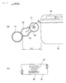
Fig. 1 of Japanese Patent Document No.JP-A-2002-206466 type vehicle 10 includes a unit-swing type engine 22 swingably mounted to a rear frame 135b and afuel tank 25 disposed below astep floor 24 on which occupant's feet are placed in front of theengine 22. (The parenthetic symbols denote symbols described in Japanese Patent Document No.JP-A-2002-206466 - As illustrated in
Fig. 2 of Japanese Patent Document No.JP-A-2002-206466 fuel tank 25 passes through a delivery tube 321 and is supplied to afuel filter 34 for purification. Then, the purified fuel is supplied to the engine via afuel pump 26. - As illustrated in
Fig. 1 , thefuel filter 34 is disposed rearward of afuel tank 25 in the anteroposterior direction of the vehicle and in a space below a cylinder head 308 and a head cover 311. In this case, also the cylinder head 308 and the head cover 311 are swung up and down along with the swing of the unit-swing type engine 22. Thus, the cylinder head 308 and the head cover 311 come close to thefuel filter 34. - To ensure a clearance between
fuel filter 34, and the cylinder head 308 and the head cover 311 encountered when they come close to each other, a method for downsizing thefuel filter 34 may be conceivable. However, if thefuel filter 34 is downsized, a replacement cycle of the fuel filter element may be short in some cases. This needs a scooter-type vehicle that can freely set the size of the fuel filter without being restricted by the swing of the unit-swing type engine. - It is an object of the present invention to provide a scooter-type vehicle that can freely set a capacity of a fuel filter without being restricted by swing of a unit-swing type engine.
- The invention relating to claim 1 is characterized in that in a scooter-type vehicle including: a body frame including a down frame extending downward from a head pipe, a lower frame extending rearward from a lower portion of the down frame and a rear frame extending rearward and obliquely upward from a rear portion of the lower frame; a step floor which is disposed above the lower frame and on which rider's feet are placed; a fuel tank disposed rearward of the down frame and below the step floor; an engine swingably supported in rear of the fuel tank by the body frame; a fuel supply passage for supplying fuel in the fuel tank toward the engine; and a fuel filter for purifying fuel disposed in an intermediate portion of the fuel supply passage; the fuel filter is disposed between the down frame and the fuel tank in the back and forth direction of the vehicle.
- The invention relating to
claim 2 is characterized in that the lower frame is composed of left and right lower frame portions, a cross pipe extending in a vehicle-width direction is spanned between the left and right lower portions at a position forward of the fuel tank, and the fuel filter is disposed between the cross pipe and the fuel tank so that a longitudinal direction of the fuel filter runs along the vehicle-width direction. - The invention relating to
claim 3 is characterized in that the fuel filter is disposed to have a lower end higher than a lower end of the cross pipe. - The invention relating to
claim 4 is characterized in that a filter support clip formed in a general C-shape and supporting the fuel filter, and the fuel filter is detachably attached to the cross pipe by elastically deforming the filter support clip. - The invention relating to
claim 5 is characterized in that the filter support clip is open toward the oblique rearward and upside of the vehicle. - The invention relating to claim 6 is characterized in that a pump-anterior filter for purifying the fuel in the fuel tank, a fuel pump disposed on the downstream side of the pump-anterior filter, the fuel filter disposed on the downstream side of the fuel pump, and an injector for injecting fuel toward the engine are arranged on the fuel supply passage in this order; in that the fuel filter is set to have finer meshes than those of the pump-anterior filter; and in that the step floor is provided above the fuel filter with an access hole and a lid used to open and close the access hole.
- The invention relating to claim 7 is characterized in that a pressure regulator for returning part of fuel to the fuel tank when fuel pressure between the fuel pump and the injector in the fuel supply passage increases and reaches a predetermined pressure is provided on the downstream side of the fuel filter, and the pressure regulator is disposed below the access hole so as to have a longitudinal direction running along a vehicle-width direction and to adjacently align with the fuel filer in the vehicle-width direction.
- The invention relating to claim 8 is characterized in that the fuel filter is disposed at a position lower than the injector in a vertical direction of the vehicle.
- In the invention relating to claim 1, since the fuel filter is disposed between the down frame and the fuel tank, the size of the fuel filer can freely be set without being restricted by the swing of the engine located rearward of the fuel tank.
- Additionally, the space between the down frame and the fuel tank tends to become a dead space. However, according to the present invention, the fuel filter is disposed in the space defined between the down frame and the fuel tank; therefore, the dead space defined between the down frame and the fuel tank can effectively be utilized.
- In the invention relating to
claim 2, the fuel filter is disposed such that its longitudinal direction runs in the vehicle-width direction. If the longitudinal direction of the fuel filter is disposed to run along the back and forth direction of the vehicle, between the cross pipe in front of the fuel tank and the fuel tank broadens unsatisfactorily. In this regard, according to the present invention, the cross pipe and the fuel tank can be disposed as close to each other as possible, so that the vehicle can be downsized in the back and forth direction of the vehicle. - Additionally, the cross pipe is located vehicle-forward of the fuel filter and the lower frame portions are located left and right. Therefore, the fuel filter can be protected by the cross pipe and the lower frames.
- In the invention relating to
claim 3, the lower end of the fuel filter is located higher than the lower end of the cross pipe; therefore, the lower portion of the fuel filter can be protected by the cross pipe. - In the invention relating to
claim 4, the filter support clip is formed in a general C-shape and the fuel filter is detachably attached by elastically deforming the filter support clip. Therefore, the attachment and detachment work for the fuel filter can easily be performed without using a tool. - In the invention relating to
claim 5, since the filter support clip is open toward the oblique rearward and upside of the vehicle, the attachment and detachment direction of the fuel filter is an oblique direction. A short distance, between the filter support clip and the fuel tank in the back and forth direction of the vehicle, necessary to attach and detach the fuel filter is required compared with the case where the attachment and detachment direction is a horizontal direction. Therefore, the fuel filter and the fuel tank can be disposed close to each other. Thus, the vehicle can be downsized in the back and forth direction thereof. - In the invention relating to claim 6, since fuel filter is set to have finer meshes than those of the pump-anterior filter, the pump-anterior filter can capture large dust and the fuel filter can capture the fine dust that has passed through the pump-anterior filter. Since the fuel filter does not capture large dust, it can be made hard to be clogged, which can reduce its replacement frequency. Additionally, since the pump-anterior filter has the coarse meshes, it can be made hard to be clogged. Thus, the pump-anterior filter can be prevented from serving as resistance against the fuel pump, so that the inexpensive fuel pump can be employed.
- Consequently, the replacement cycle of both the pump-anterior filter and the fuel filter can be lengthened and the number of maintenance can be reduced. In addition, an amount of fuel passing through the pump-anterior filter and the fuel filter can satisfactorily be maintained for a long period of time. Even if a necessary fuel flow rate increases suddenly, the pump-anterior filter and the fuel filter can sufficiently deal with such an event.
- Because of having fine meshes, the fuel filter can capture fine dust even in the case of using fuel with fine dust such as ethanol. On the other hand, the fuel filter is set to have finer meshes than those of the pump-anterior filter in order to make it possible to use even fuel with fine dust such as ethanol. Therefore, the fuel filter becomes shorter in replacement cycle than the pump-anterior filter. However, since the step floor is provided with the access hole and the openable/closable lid for maintenance, the replacement work can be facilitated.
- Further, since the fuel filter can be attached to and detached from the filter support clip without use of a tool, it is not necessary for the step floor to be provided with such a large access hole as to receive a tool insertable thereinto. Therefore, it is possible to make small the access hole and the maintenance lid provided in the step floor, the maintenance lid being used to open and close the access hole.
- In the invention relating to claim 7, the pressure regulator is disposed to have a longitudinal direction running along a vehicle-width direction and to adjacently align with the fuel filer in the vehicle-width direction. In this way, by using the access hole provided in the step floor, the attachment and detachment of the pressure regulator can be done along with the attachment and detachment of the fuel filter.
- In the invention relating to claim 8, the fuel filter is disposed at a position lower than the injector. Therefore, in the case where the vehicle is parked for a long period of time, it is possible to prevent fuel from leaking from the injector due to the weight of the fuel staying in the fuel filter.
-
-
Fig. 1 is a lateral view of a scooter-type vehicle according to the present invention. -
Fig. 2 is a lateral view of a fuel supply device disposed on a body frame. -
Fig. 3 is a plan view of an essential portion of the scooter-type vehicle. -
Fig. 4 is a view for assistance in explaining attachment of a fuel filter. -
Fig. 5 is a view for assistance in explaining a filter support clip. -
Fig. 6 is a perspective view of the scooter-type vehicle, illustrating an access hole. -
Fig. 7 is a plan view illustrating the positional relationship between the access hole and the fuel filter. -
Fig. 8 is a view for assistance in explaining opening and closing of a lid of the access hole. -
Fig. 9 is a cross-sectional view of the fuel filter according to the present invention. -
Fig. 10 is a cross-sectional view of a pressure regulator according to the present invention. - Embodiment of the present invention will hereinafter be described with reference to the accompanying drawings. Incidentally, the drawings shall be viewed in the direction of reference symbols. In addition, arrows (FRONT) in the drawings represent the front of a vehicle.
- An embodiment of the present invention is first described with reference to the drawings.
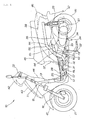
- Referring to
Fig. 1 , a scooter-type vehicle 10 as a motorcycle includes a body frame 11 serving as a framework. The body frame 11 includes ahead pipe 12 forming a front end portion; adown frame 13 extending downward from thehead pipe 12; and a pair of left and rightlower frames reference symbol 14L on the front side is illustrated) extending rearward from the lower portion of thedown frame 13. The body frame 11 further includes a pair of left and right rear frames 15L, 15R (onlyreference symbol 15L on the front side is illustrated) extending rearward and obliquely upward from corresponding rear portions of thelower frames link support brackets 16, 17 (onlyreference symbol 16 on the front side is illustrated) joined to the corresponding respective intermediate portions of therear frames - The
head pipe 12 is steerably attached to afront fork 18. Afront wheel 21 is attached to a lower end of thefront fork 18. Ahandlebar 22 is attached to an upper end of thehead pipe 12. - The scooter-
type vehicle 10 is such that apower unit 24 is vertically swingably mounted to thelink support brackets 16, 17 via alink 23. Arear cushion unit 25 is mounted so as to be spanned between the rear end portion of thepower unit 24 and the rear end portion of the rear frame 15. - A pair of left and
right floor pipes 26, 27 (onlyreference symbol 26 on the front side is illustrated) is provided above the correspondinglower frames floor pipes step floor 28 on which operator's feet are placed. Afuel tank 32 is provided on thelower frames tank support brackets 31. - The
power unit 24 is composed of anengine 33 forming a front portion and a continuouslyvariable transmission 34 integrally coupled to a rear portion of theengine 33. Arear wheel 35 is attached to a rear portion of the continuouslyvariable transmission 34. - Incidentally,
reference symbol 36 denotes an air cleaner, 37 denotes a body-central cover, 38 denotes a body-rear cover, 41 denotes a front fender, and 42 denotes a handlebar cover. In addition,reference symbol 43 denotes a front cover, 44 denotes a leg shield, 45 denotes a seat, 46 denotes a tail lamp, 47 denotes a rear fender, 48 denotes an exhaust pipe, 51 denotes a muffler and 52 denotes a main stand. - A fuel supply device is next described.
- Referring to
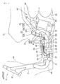
Fig. 2 , afuel supply device 53 includes thefuel tank 32 and afuel supply passage 54 for supplying the fuel in thefuel tank 32 to theengine 33. A pump-anterior filter 55, afuel pump 56, afuel filter 57, and aninjector 58 are arranged on thefuel supply passage 54 in this order. The pump-anterior filter 55 is provided to purify the fuel in thefuel tank 32. Thefuel pump 56 is disposed on the downstream side of the pump-anterior filter 55. Thefuel filter 57 is disposed on the downstream side of thefuel pump 56. Theinjector 58 is provided to inject fuel toward theengine 33. Incidentally, the pump-anterior filter 55 and thefuel pump 56 are installed in thefuel tank 32 and theinjector 58 is mounted to anintake pipe 64. - A
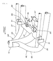
cross pipe 61 is spanned between the left and rightlower frames reference symbol 14L on the front side is illustrated). A central portion of thecross pipe 61 is coupled to a lower end of the down frame 13 (seeFig. 4 ). - The
fuel filter 57 is disposed such that its lower end is located at a position higher by distance L1 than the lower end of thecross pipe 61 as viewed from the side of the vehicle. Thefuel filter 57 is disposed between thedown frame 13 and thefuel tank 32. - The
fuel filter 57 is set to have finer meshes than those of the pump-anterior filter 55. In addition, thefuel filter 57 is disposed at a position lower than theinjector 58 in the vertical direction of the vehicle. - The
fuel filter 57 is set to have finer meshes than those of the pump-anterior filter 55, that is, the mesh coarseness of thefuel filter 57 is made different from that of the pump-anterior filter 55. Therefore, even in the case of using fuel with fine dust such as ethanol, the fine dust that has not been captured by the pump-anterior filter 55 can be captured by thefuel filter 57. Thus, fuel such as ethanol or the like can be used. - Incidentally, the
fuel tank 32 is a container formed by putting a tank upper-half body 32b protruding upward over a tank lower-half body 32a concaved downward and joining theirflange portions 79 together for integration. The tank upper-half body 32b is provided at a rear portion with an upward extendingfiller neck 39, which is provided with afuel cap 67. Thefuel pump 56 is inserted into from above and mounted in the front portion of the tank upper-half body 32b. Incidentally, the pump-anterior filter 55 is attached to thefuel pump 56. - The
engine 33 includes acrankcase 59 housing a crankshaft (not illustrated) and acylinder portion 63 protruding from thecrankcase 59 toward the front of the vehicle. Thecylinder portion 63 is composed of acylinder block 63a, acylinder head 63b and ahead cover 63c in order from thecrankcase 59. - An intake device is next described.
- Referring to
Fig. 2 , anintake device 62 includes anintake pipe 64 connected to an upper portion of thecylinder head 63b, athrottle body 65 connected to theintake pipe 64, and theair cleaner 36 connected to thethrottle body 65 via a connectingtube 66. - A
fuel supply device 53 to which fuel is supplied from thefuel tank 32 is connected to theintake pipe 64. - Referring to
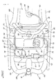
Fig. 3 , thelower frames lower frame portion 68 and a rightlower frame portion 69, respectively. Across pipe 61 extending in the vehicle-width direction is spanned between the left and rightlower frame portions fuel pump 32. Thefuel tank 32 is supported by fastening members passed through corresponding fastening holes 70 and fastened at four positions to the fuel tank support brackets (reference symbols 31 inFig. 1 ) provided on the left and rightlower frame portions - The
fuel supply device 53 includes thefuel tank 32, thefuel supply passage 54, apressure regulator 76 connected between afuel pipe 75 and afuel pipe 82, and areturn pipe 77 connecting thepressure regulator 76 with thefuel tank 32. Thefuel supply passage 54 includes a fuel pipe 71 connecting thefuel filter 57 with thefuel pump 56 attached to thefuel tank 32; andfuel pipes fuel filter 57 with theinjector 58. - The fuel pipe 71 is held by a
pipe clip 72 welded to the upper surface of thefuel tank 32 and pipe clips 73, 74 provided on thefloor pipe 26, and led from thefuel pump 56 to thefuel filter 57 located forward of thefuel tank 32 to connect thefuel pump 56 with thefuel filer 57. Thefuel pipe 75 is connected to thefuel filter 57 and to thepressure regulator 76 disposed to adjacently align with thefuel filer 57 in the vehicle-width direction. Thefuel pipe 82 is connected to an upstream branch side of thepressure regulator 76. In addition, thefuel pipe 82 is held bypipe clips 83, 84 provided on thefuel tank 32 and apipe clip 81 provided on thecylinder portion 63 and connected to theinjector 58. In this way, fuel in thefuel tank 32 is supplied from theinjector 58 toward theengine 33. - The
fuel filter 57 is disposed between thecross pipe 61 and thefuel tank 32 so that its longitudinal axis extends in the vehicle-width direction similarly to thecross pipe 61 extending in the vehicle-width direction. - The
pressure regulator 76 is disposed to have a longitudinal direction extending along the vehicle-width direction and to adjacently align with thefuel filter 57 in the vehicle-width direction similarly to thecross pipe 61 extending in the vehicle-width direction. - The
pressure regulator 76 is provided to return part of the fuel to a lower portion of thefuel tank 32 via thereturn pipe 77 when fuel pressure between thefuel pump 56 and theinjector 58 in thefuel supply passage 54 increases and reaches a predetermined pressure. Thereturn pipe 77 is held by apipe clip 78 provided on the rightlower frame portion 69, and led from thepressure regulator 76 to the lower portion of thefuel tank 32 located on the back of thepressure regulator 76 to connect thepressure regulator 76 with the lower portion of thefuel tank 32. - Incidentally, the
fuel filter 57 is held by a filter support clip 85 (detailed later) provided on thecross pipe 61. Thepressure regulator 76 is held by aregulator support clip 86 provided on thecross pipe 61.Reference symbol 87 denotes a cross plate spanned between the left andright floor pipes - A description is next given of attachment of the
fuel filter 57 and thepressure regulator 76. - Referring to
Fig. 4 , thefilter support clip 85 attached to thecross pipe 61 is formed of an elastically deformable material in a general C-shape. In addition, an openingportion 88 of thefilter support clip 85 slightly rolls outwardly. Thus, it becomes easy for thefilter support clip 85 to receive a cylindrical object with a diameter greater than the width of the openingportion 88. - The
fuel filter 57 has a cylindrical shape. Thefuel filer 57 is displaced along arrow (1) and pushed into the openingportion 88 of thefilter support clip 85. Thus, the openingportion 88 of thefilter support clip 85 is elastically deformed and broadened. When thefuel filter 57 enters the back of the openingportion 88, the openingportion 88 becomes narrow to hold thefuel filter 57. - Similarly, also the
regulator support clip 86 is formed of an elastically deformable material in a general C-shape. - Also for the attachment of the
pressure regulator 76, similarly to thefuel filer 57, thepressure regulator 76 is displaced along arrow (2) and pressed into an openingportion 89 of theregulator support clip 86. Thus, thepressure regulator 76 is attached to theregulator support clip 86. - Incidentally, the left and
right floor pipes respective stays 91 provided on the left and rightlower frame portions - The
filter support clip 85 is next described in detail. - Referring to
Fig. 5(a) , the generally C-shapedfilter support clip 85 is provided on thecross pipe 61 so as to open toward the obliquely rearward upside of the vehicle. In this way, also the attachment and detachment direction of thefuel filter 57 is an oblique direction as indicated with arrow (3). A distance L2 of a working space in the back and forth direction of the vehicle can be reduced compared with the case where the attachment and detachment direction of thefuel filter 57 is a horizontal direction. In addition, thefuel filter 57 and thefuel tank 32 can be disposed close to each other. - Incidentally, the same holds true for the regulator support clip (
reference symbol 86 inFig. 4 ). -
Fig. 5(b) is a view as viewed from arrow "b" ofFig. 5(a) . Thefilter support clip 85 is provided with an elongate hole in the bottom thereof. By welding this portion thefilter support clip 85 can be secured to thecross pipe 61.Reference symbol 92 denotes a welding portion. Incidentally, this applies to theregulator support clip 86. - A description is next given of an access hole of the
fuel filter 57. Referring toFig. 6 , thestep floor 28 is provided with anaccess hole 93 above thefuel filter 57 and thepressure regulator 76. In addition, thestep floor 28 is provided with alid 94 used to open and close theaccess hole 93. Theaccess hole 93 is provided with a recessedportion 95. One's finger is put into the recessedportion 95 and put on a projectingportion 96 of thelid 94 for opening and closing thelid 94. - Incidentally,
reference symbol 97 denotes an oil filler lid. - The position of the
access hole 93 is next described. - Referring to
Fig. 7 , theaccess hole 93 opens from the rear portion of thefuel filter 57 and of thepressure regulator 76 to the front portion of thefuel tank 32. Thefuel filter 57 is not supported by thefilter support clip 85 by use of a tool or the like. Therefore, it is not necessary for theaccess hole 93 provided in thestep floor 28 to open immediately above thefuel filter 57. It is necessary for theaccess hole 93 only to open from the rear portion of thefuel filter 57 to the front of thefuel tank 32 at minimum. Consequently, the length of theaccess hole 93 can be reduced in the back and forth direction of the vehicle. - The vehicle-widthwise length of the
access hole 93 is from the left end of thefuel filter 57 to the right end of thepressure regulator 76. - A description is next given of the opening and closing of the
lid 94 of theaccess hole 93. - Referring to
Fig. 8 , thelid 94 used to open and close theaccess hole 93 is provided with ahinge 98. One's finger is put into the recessedportion 95 and thelid 94 is opened and closed around thehinge 98 as indicated with arrow (4). The projectingportion 96 is provided with aclaw 99. Thisclaw 93 engages thestep floor 28 to maintain thelid 94 in the closed state. - While the
lid 94 is opened, thefuel filter 57 depicted with an imaginary line is taken out as indicated with arrow (5). - The
fuel filter 57 is next described. - Referring to
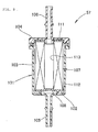
Fig. 9 , thefuel filter 57 includes afilter case 101 and afilter assembly 102 housed in thefilter case 101. - The
filter case 101 is composed of a bottomedcylindrical case body 103 and acase cover 104 covering an opening portion of thecase body 103. - The
case body 103 is provided with afuel suction port 105 for sucking fuel coupled to the fuel pipe (reference symbol 71 inFig. 3 ) on the side of the fuel tank (reference symbol 32 inFig. 3 ). In addition, thecase cover 104 is provided with afuel discharge port 106 for discharging fuel coupled to the fuel pipe (reference symbol 75 inFig. 3 ) on the side of the injector (reference symbol 58 inFig. 3 ). - The
filter assembly 102 includes acylindrical filter 107 made of filter-paper and frames 108, 111 supporting both ends of thefilter 107. Thefilter assembly 102 is fixedly put between thecase body 103 and thecase cover 104. - Fuel is sucked into the
filter case 101 from thefuel suction port 105, passes through thefilter 107 in such a manner as to flow from its outercircumferential surface 112 to its innercircumferential surface 113 for filtration, and is discharged from thefuel discharge port 106 to the outside of thefilter case 101. - Referring to
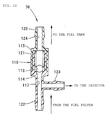
Fig. 10 , thepressure regulator 76 includes acase 116 formed by joining a resin-madefirst case 114 to a resin-madesecond case 115; a steel-madespherical valve body 118 for opening and closing a through-hole 117 bored in a one end side bottom of thecase 116; and acompression coil spring 121 for biasing thevalve body 118 to close the through-hole 117. In addition, thepressure regulator 76 includes afuel suction port 122 bored with the through-hole 117; afuel discharge port 123 formed in an intermediate portion of thefuel suction port 122; and afuel return port 125 bored with a through-hole 124 bored in the other end side bottom of thecase 116. - The
fuel suction port 122 is connected to the fuel filter (reference symbol 57 inFig. 3 ). Thefuel discharge port 123 is connected to the injector (reference symbol 58 inFig. 3 ). Thefuel return port 125 is connected to the fuel tank (reference symbol 32 inFig. 3 ). - As early illustrated in
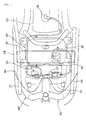
Figs. 1 ,2 and3 , in the scooter-type vehicle 10 including the body frame 11 including thedown frame 13 extending downward from thehead pipe 12, thelower frames down frame 13 and therear frames lower frames step floor 28 which is disposed above thelower frames fuel tank 32 disposed rearward of thedown frame 13 and below thestep floor 28; theengine 33 swingably supported in rear of thefuel tank 32 by the body frame 11; thefuel supply passage 54 for supplying the fuel in thefuel tank 32 toward theengine 32; and thefuel filter 57 for purifying fuel disposed in the intermediate portion of thefuel supply passage 54, thefuel filter 57 is disposed between thedown frame 13 and thefuel tank 32 in the back and forth direction of the vehicle. - With this configuration, the size of the
fuel filter 57 can freely be set without being restricted by the swing of theengine 33 disposed in rear of thefuel tank 32. - Additionally, the space between the
down frame 13 and thefuel tank 32 tends to become a dead space; however, in the present invention, thefuel filter 57 is disposed in the space defined between thedown frame 13 and thefuel tank 32. Therefore, the dead spaced defined between thedown frame 13 and thefuel tank 32 can effectively be utilized. - As early illustrated in
Fig. 3 , thelower frames lower frame portion 68 and the rightlower frame portion 69, respectively. Thecross pipe 61 extending in the vehicle-width direction is spanned between the left and rightlower frame portions fuel pump 32. Thefuel filter 57 is disposed between thecross pipe 61 and thefuel tank 32 so that the longitudinal direction of thefuel filter 57 extends in the vehicle-width direction. - With this configuration, the
cross pipe 61 and thefuel tank 32 can be disposed as close to each other as possible; therefore, the vehicle can be downsized in the back and forth direction of the vehicle. - Additionally, the
cross pipe 61 exists in vehicle-front of thefuel filter 57 and thelower frame portions fuel filter 57 can be protected by thecross pipe 61 and thelower frames - As early illustrated in
Fig. 2 , thefuel filter 57 is disposed such that its lower end is located at a position higher than the lower end of thecross pipe 61 as viewed from the side of the vehicle. - With this configuration, the lower portion of the
fuel filter 57 can be protected by thecross pipe 61. - As early illustrated in
Fig. 4 , thefilter support clip 85 formed in a general C-shape and supporting thefuel filter 57 is provided on thecross pipe 61. Thefuel filter 57 is detachably attached to thecross pipe 61 by elastically deforming thefilter support clip 85. - With this configuration, attachment and detachment work for the
fuel filter 57 can easily be performed without using a tool. - As early illustrated in
Fig. 5 , thefilter support clip 85 is open toward the obliquely rearward upside of the vehicle. In this way, the attachment and detachment direction of thefuel filter 57 is an oblique direction. A short distance, between thefilter support clip 85 and thefuel tank 32 in the back and forth direction of the vehicle, necessary to attach and detach the fuel filter is required compared with the case where the attachment and detachment direction of thefuel filter 57 is a horizontal direction. Therefore, thefuel filter 57 and thefuel tank 32 can be disposed close to each other. Thus, the vehicle can be downsized in the back and forth direction of the vehicle. - As early illustrated in
Figs. 2 ,3 ,6 ,7 and8 , the pump-anterior filter 55 for purifying the fuel in thefuel tank 32, thefuel pump 56 disposed on the downstream side of the pump-anterior filter 55, thefuel filter 57 disposed on the downstream side of thefuel pump 56, and theinjector 58 for injecting fuel toward theengine 33 are arranged on thefuel supply passage 54 in this order. Thefuel filter 57 is set to have finer meshes than those of the pump-anterior filter 55. Thestep floor 28 is provided with theaccess hole 93 above thefuel filter 57. In addition, thestep floor 28 is provided with thelid 94 used to open and close theaccess hole 93. - With this configuration, the pump-
anterior filter 55 can capture large dust and thefuel filter 57 can capture the fine dust that has passed through the pump-anterior filter 55. Since thefuel filter 57 does not capture large dust, it can be made hard to be clogged, which can reduce its replacement frequency. Additionally, since the pump-anterior filter 55 has the coarse meshes, it can be made hard to be clogged. Thus, the pump-anterior filter 55 can be prevented from serving as resistance against thefuel pump 56, so that theinexpensive fuel pump 56 can be employed. - Consequently, the replacement cycle of both the pump-
anterior filter 55 and thefuel filter 57 can be lengthened and the number of maintenance can be reduced. In addition, an amount of fuel passing through the pump-anterior filter 55 and thefuel filter 57 can satisfactorily be maintained for a long period of time. Even if a necessary fuel flow rate increases suddenly, the pump-anterior filter and the fuel filter can sufficiently deal with such an event. - Since the
fuel filter 57 has fine meshes, it can capture fine dust even in the case of using fuel with fine dust such as ethanol. On the other hand, thefuel filter 57 is set to have finer meshes than those of the pump-anterior filter 55 in order to make it possible to use even fuel with fine dust such as ethanol. Therefore, thefuel filter 57 becomes shorter in replacement cycle than the pump-anterior filter 55. However, since thestep floor 28 is provided withaccess hole 93 and the openable/closable lid 94 for maintenance, the replacement work can be facilitated. - Further, since the
fuel filter 57 can be attached to and detached from thefilter support clip 85 without use of a tool, it is not necessary for thestep floor 28 to be provided with such alarge access hole 93 as to receive a tool insertable thereinto. Therefore, it is possible to make small theaccess hole 93 and themaintenance lid 94 provided in thestep floor 28, themaintenance lid 94 being used to open and close theaccess hole 93. - As early illustrated in
Figs. 6 ,7 and8 , thepressure regulator 76 for returning part of fuel to thefuel tank 32 when fuel pressure between thefuel pump 56 and theinjector 58 in thefuel supply passage 54 increases and reaches a predetermined pressure is provided on the downstream side of thefuel filter 57. Thepressure regulator 76 is disposed below theaccess hole 93 so as to have a longitudinal direction running along the vehicle-width direction and to adjacently align with thefuel filer 57 in the vehicle-width direction. - With this configuration, by using the
access hole 93 provided in thestep floor 28, the attachment and detachment of thepressure regulator 76 can be done along with the attachment and detachment of thefuel filter 57. - As early illustrated in
Fig. 2 , thefuel filter 57 is disposed at a position lower than theinjector 58 in the vertical direction of the vehicle. - With this configuration, in the case where the vehicle is parked for a long period of time, it is possible to prevent fuel from leaking from the
injector 58 due to the weight of the fuel staying in thefuel filter 57. - Incidentally, it is reasonable that the present embodiment is applied to not only the scooter-
type vehicle 10 on which the engine runs on gasoline is mounted but also the scooter-type vehicle 10 on which theengine 33 runs on bio-fuel such as ethanol or the like is mounted, provided that such fuel can be purified by thefuel filter 57. - The present invention is suitable for scooter-type vehicles provided with a fuel filter on the outside of a fuel tank.
- The present invention is directed to provide a scooter-type vehicle that can freely set a capacity of a fuel filter without being restricted by swing of a unit-swing type engine.
- A
cross pipe 61 is spanned between a pair of left and rightlower frames down frame 13 is connected to a central portion of thecross pipe 61. Afuel filter 57 is disposed so that its lower end is higher by distance L1 than the lower end ofcross pipe 61. Thefuel filter 57 is disposed between thedown frame 13 and thefuel tank 32. - Since the fuel filter is disposed in front of the fuel tank, it is not restricted by the swing of an engine located rearward of the fuel tank. Because of no restriction, a capacity of the fuel filter can freely be set.
Claims (8)
- A scooter-type vehicle (10), comprising:a body frame (11) including a down frame (13) extending downward from a head pipe (12), a lower frame (14L, 14R) extending rearward from a lower portion of the down frame (13) and a rear frame(15L, 15R) extending rearward and obliquely upward from a rear portion of the lower frame (14L, 14R);a step floor (28) which is disposed above the lower frame (14L, 14R) and on which rider's feet are placed;a fuel tank (32) disposed rearward of the down frame (13) and below the step floor (28);an engine (33) swingably supported in rear of the fuel tank (32) by the body frame (11);a fuel supply passage (54) for supplying fuel in the fuel tank (32) toward the engine (33); anda fuel filter (57) for purifying fuel disposed in an intermediate portion of the fuel supply passage (54);wherein the fuel filter (57) is disposed between the down frame (13) and the fuel tank (32) in the back and forth direction of the vehicle.
- The scooter-type vehicle (10) according to claim 1,
wherein the lower frame (14L, 14R) is composed of left and right lower frame portions (68, 69), a cross pipe (61) extending in a vehicle-width direction is spanned between the left and right lower portions (68, 69) at a position forward of the fuel tank (32), and the fuel filter (57) is disposed between the cross pipe (61) and the fuel tank (32) so that a longitudinal direction of the fuel filter (57) runs along the vehicle-width direction. - The scooter-type vehicle (10) according to claim 2,
wherein the fuel filter (57) is disposed to have a lower end higher than a lower end of the cross pipe (61). - The scooter-type vehicle (10) according to claim 3,
wherein a filter support clip (85) formed in a general C-shape and supporting the fuel filter (57), and the fuel filter (57) is detachably attached to the cross pipe (61) by elastically deforming the filter support clip (85). - The scooter-type vehicle (10) according to claim 4,
wherein the filter support clip (85) is open toward the oblique rearward and upside of the vehicle. - The scooter-type vehicle (10) according to claim 4 or 5,
wherein a pump-anterior filter (55) for purifying the fuel in the fuel tank (32), a fuel pump (56) disposed on the downstream side of the pump-anterior filter (55), the fuel filter (57) disposed on the downstream side of the fuel pump (56), and an injector (58) for injecting fuel toward the engine (33) are arranged on the fuel supply passage (54) in this order;
the fuel filter (57) is set to have finer meshes than those of the pump-anterior filter (55); and
the step floor (28) is provided above the fuel filter (57) with an access hole (93) and a lid (94) used to open and close the access hole (93). - The scooter-type vehicle (10) according to claim 6,
wherein a pressure regulator (76) for returning part of fuel to the fuel tank (32) when fuel pressure between the fuel pump (56) and the injector (58) in the fuel supply passage (54) increases and reaches a predetermined pressure is provided on the downstream side of the fuel filter (57), and
the pressure regulator (76) is disposed below the access hole (93) so as to have a longitudinal direction running along a vehicle-width direction and to adjacently align with the fuel filer (57) in the vehicle-width direction. - The scooter-type vehicle (10) according to claim 6 or 7,
wherein the fuel filter (57) is disposed at a position lower than the injector (58) in a vertical direction of the vehicle.
Applications Claiming Priority (1)
| Application Number | Priority Date | Filing Date | Title |
|---|---|---|---|
| JP2009228796A JP5371669B2 (en) | 2009-09-30 | 2009-09-30 | Scooter type vehicle |
Publications (3)
| Publication Number | Publication Date |
|---|---|
| EP2305545A2 true EP2305545A2 (en) | 2011-04-06 |
| EP2305545A3 EP2305545A3 (en) | 2012-09-05 |
| EP2305545B1 EP2305545B1 (en) | 2013-07-24 |
Family
ID=42972659
Family Applications (1)
| Application Number | Title | Priority Date | Filing Date |
|---|---|---|---|
| EP10174134.6A Active EP2305545B1 (en) | 2009-09-30 | 2010-08-26 | Scooter-type vehicle |
Country Status (6)
| Country | Link |
|---|---|
| US (1) | US8439145B2 (en) |
| EP (1) | EP2305545B1 (en) |
| JP (1) | JP5371669B2 (en) |
| CN (1) | CN102030060B (en) |
| BR (1) | BRPI1003777B1 (en) |
| ES (1) | ES2424460T3 (en) |
Cited By (2)
| Publication number | Priority date | Publication date | Assignee | Title |
|---|---|---|---|---|
| EP2860385A1 (en) * | 2013-10-09 | 2015-04-15 | Yamaha Hatsudoki Kabushiki Kaisha | Saddle riding type vehicle |
| EP3770052A4 (en) * | 2018-03-23 | 2021-04-07 | Honda Motor Co., Ltd. | Pipe frame strengthening structure |
Families Citing this family (14)
| Publication number | Priority date | Publication date | Assignee | Title |
|---|---|---|---|---|
| JP5184479B2 (en) * | 2009-09-29 | 2013-04-17 | 本田技研工業株式会社 | Motorcycle fuel supply system |
| JP5520623B2 (en) * | 2010-01-29 | 2014-06-11 | 本田技研工業株式会社 | Fuel supply device |
| JP5623775B2 (en) * | 2010-03-31 | 2014-11-12 | 本田技研工業株式会社 | Motorcycle |
| JP5694788B2 (en) * | 2011-01-17 | 2015-04-01 | 本田技研工業株式会社 | Saddle riding vehicle |
| US9457869B2 (en) * | 2011-11-25 | 2016-10-04 | Honda Motor Co., Ltd. | Electric scooter |
| BR112014013212A2 (en) * | 2011-12-02 | 2020-03-03 | Honda Motor Co Ltd | The frame structure of motor scooter type vehicles |
| AU2012367781A1 (en) * | 2011-12-27 | 2014-07-17 | Tvs Motor Company Limited | Vehicle |
| JP2017121849A (en) * | 2016-01-06 | 2017-07-13 | ヤマハ発動機株式会社 | Saddle-riding type vehicle |
| JP6553808B2 (en) * | 2016-03-30 | 2019-07-31 | 本田技研工業株式会社 | Body cover structure in a saddle-ride type vehicle |
| JP6828158B2 (en) * | 2017-06-29 | 2021-02-10 | 本田技研工業株式会社 | Motorcycle |
| CN110920788B (en) * | 2018-09-14 | 2021-08-13 | 雅马哈发动机株式会社 | Saddle-ride type vehicle |
| USD953935S1 (en) * | 2019-04-26 | 2022-06-07 | Gogoro Inc. | Two-wheeled vehicle and/or toy replica thereof |
| US10768656B1 (en) * | 2019-05-14 | 2020-09-08 | Volvo Car Corporation | Vehicle brake pedal booster pushrod interface assembly |
| JP7199460B2 (en) * | 2021-03-12 | 2023-01-05 | 本田技研工業株式会社 | saddle-riding vehicle |
Citations (1)
| Publication number | Priority date | Publication date | Assignee | Title |
|---|---|---|---|---|
| JP2002206466A (en) | 2001-01-10 | 2002-07-26 | Honda Motor Co Ltd | Method of controlling electromagnetic fuel pump |
Family Cites Families (20)
| Publication number | Priority date | Publication date | Assignee | Title |
|---|---|---|---|---|
| JPH0631054B2 (en) * | 1984-12-13 | 1994-04-27 | ヤマハ発動機株式会社 | Mounting structure for fuel system parts in vehicles |
| US4726439A (en) * | 1985-10-05 | 1988-02-23 | Honda Giken Kogyo Kabushiki Kaisha | Trunk structure in scooter-type vehicles |
| US4964483A (en) * | 1987-09-25 | 1990-10-23 | Honda Giken Kogyo Kabushiki Kaisha | Motor scooter |
| JP2847372B2 (en) * | 1988-09-27 | 1999-01-20 | 本田技研工業株式会社 | Scooter type vehicle |
| US5433286A (en) * | 1988-09-27 | 1995-07-18 | Honda Giken Kogyo Kabushiki Kaisha | Motorcycle |
| JP3075806B2 (en) * | 1991-10-07 | 2000-08-14 | ヤマハ発動機株式会社 | Arrangement structure of vehicle fuel pump |
| JP3489805B2 (en) * | 1997-01-21 | 2004-01-26 | 本田技研工業株式会社 | Motorcycle |
| JP3340637B2 (en) * | 1997-01-21 | 2002-11-05 | 本田技研工業株式会社 | Connection structure between scooter type motorcycle footrest and floor skirt |
| JP3737336B2 (en) * | 2000-03-30 | 2006-01-18 | 本田技研工業株式会社 | Scooter type fuel tank mounting structure |
| US6439546B1 (en) * | 2000-08-29 | 2002-08-27 | Walbro Corporation | Carburetor with fuel vapor control |
| JP3889214B2 (en) * | 2000-09-29 | 2007-03-07 | 本田技研工業株式会社 | Vehicle fuel supply system |
| JP4077173B2 (en) * | 2001-05-11 | 2008-04-16 | 本田技研工業株式会社 | Scooter type vehicle |
| JP4290950B2 (en) * | 2001-10-19 | 2009-07-08 | ヤマハ発動機株式会社 | Overturn detection device for motorcycles |
| TW561262B (en) * | 2001-10-19 | 2003-11-11 | Yamaha Motor Co Ltd | Tipping detecting device for a motorcycle |
| JP4391756B2 (en) * | 2003-03-20 | 2009-12-24 | 本田技研工業株式会社 | Motorcycle fuel pump arrangement structure |
| JP2006017040A (en) * | 2004-07-02 | 2006-01-19 | Toyota Motor Corp | Diesel fuel filter and fuel passage including the diesel fuel filter |
| JP4784426B2 (en) * | 2006-07-28 | 2011-10-05 | スズキ株式会社 | Motorcycle fuel supply system |
| JP2008151090A (en) * | 2006-12-20 | 2008-07-03 | Kyosan Denki Co Ltd | Diesel filter |
| JP4888114B2 (en) * | 2006-12-28 | 2012-02-29 | スズキ株式会社 | Motorcycle fuel supply system |
| JP5227932B2 (en) * | 2009-09-30 | 2013-07-03 | 本田技研工業株式会社 | Scooter type vehicle |
-
2009
- 2009-09-30 JP JP2009228796A patent/JP5371669B2/en active Active
-
2010
- 2010-08-26 ES ES10174134T patent/ES2424460T3/en active Active
- 2010-08-26 EP EP10174134.6A patent/EP2305545B1/en active Active
- 2010-09-03 US US12/875,656 patent/US8439145B2/en not_active Expired - Fee Related
- 2010-09-21 BR BRPI1003777-2A patent/BRPI1003777B1/en active IP Right Grant
- 2010-09-27 CN CN201010296787.2A patent/CN102030060B/en active Active
Patent Citations (1)
| Publication number | Priority date | Publication date | Assignee | Title |
|---|---|---|---|---|
| JP2002206466A (en) | 2001-01-10 | 2002-07-26 | Honda Motor Co Ltd | Method of controlling electromagnetic fuel pump |
Cited By (2)
| Publication number | Priority date | Publication date | Assignee | Title |
|---|---|---|---|---|
| EP2860385A1 (en) * | 2013-10-09 | 2015-04-15 | Yamaha Hatsudoki Kabushiki Kaisha | Saddle riding type vehicle |
| EP3770052A4 (en) * | 2018-03-23 | 2021-04-07 | Honda Motor Co., Ltd. | Pipe frame strengthening structure |
Also Published As
| Publication number | Publication date |
|---|---|
| JP5371669B2 (en) | 2013-12-18 |
| CN102030060B (en) | 2014-12-10 |
| US8439145B2 (en) | 2013-05-14 |
| ES2424460T3 (en) | 2013-10-02 |
| CN102030060A (en) | 2011-04-27 |
| EP2305545B1 (en) | 2013-07-24 |
| BRPI1003777A2 (en) | 2013-01-15 |
| JP2011073629A (en) | 2011-04-14 |
| BRPI1003777B1 (en) | 2019-08-20 |
| US20110073397A1 (en) | 2011-03-31 |
| EP2305545A3 (en) | 2012-09-05 |
Similar Documents
| Publication | Publication Date | Title |
|---|---|---|
| EP2305545B1 (en) | Scooter-type vehicle | |
| EP2305544B1 (en) | Scooter-type vehicle | |
| US8534406B2 (en) | Motorcycle | |
| EP2502812B1 (en) | Evaporated fuel treatment device for motorcycle | |
| JP5039412B2 (en) | Vehicle fuel supply device | |
| EP2332813B1 (en) | Scooter type vehicle | |
| EP2375049B1 (en) | Motorcycle | |
| EP2502811B1 (en) | Evaporated fuel treatment device for motorcycle | |
| JP5011422B2 (en) | Vehicle fuel supply device | |
| EP2502813B1 (en) | Evaporated fuel treatment device for motorcycle | |
| EP2368789B1 (en) | Motor scooter type vehicle | |
| EP2371690B1 (en) | Motor scooter type vehicle | |
| EP2371689B1 (en) | Motorcycle |
Legal Events
| Date | Code | Title | Description |
|---|---|---|---|
| PUAI | Public reference made under article 153(3) epc to a published international application that has entered the european phase |
Free format text: ORIGINAL CODE: 0009012 |
|
| 17P | Request for examination filed |
Effective date: 20100826 |
|
| AK | Designated contracting states |
Kind code of ref document: A2 Designated state(s): AL AT BE BG CH CY CZ DE DK EE ES FI FR GB GR HR HU IE IS IT LI LT LU LV MC MK MT NL NO PL PT RO SE SI SK SM TR |
|
| AX | Request for extension of the european patent |
Extension state: BA ME RS |
|
| PUAL | Search report despatched |
Free format text: ORIGINAL CODE: 0009013 |
|
| AK | Designated contracting states |
Kind code of ref document: A3 Designated state(s): AL AT BE BG CH CY CZ DE DK EE ES FI FR GB GR HR HU IE IS IT LI LT LU LV MC MK MT NL NO PL PT RO SE SI SK SM TR |
|
| AX | Request for extension of the european patent |
Extension state: BA ME RS |
|
| RIC1 | Information provided on ipc code assigned before grant |
Ipc: B62K 11/10 20060101ALI20120731BHEP Ipc: B62J 37/00 20060101AFI20120731BHEP |
|
| 17Q | First examination report despatched |
Effective date: 20120821 |
|
| GRAP | Despatch of communication of intention to grant a patent |
Free format text: ORIGINAL CODE: EPIDOSNIGR1 |
|
| RIC1 | Information provided on ipc code assigned before grant |
Ipc: B62K 11/10 20060101ALI20130122BHEP Ipc: F02M 37/00 20060101ALI20130122BHEP Ipc: B62J 37/00 20060101AFI20130122BHEP Ipc: F02M 37/22 20060101ALI20130122BHEP |
|
| GRAS | Grant fee paid |
Free format text: ORIGINAL CODE: EPIDOSNIGR3 |
|
| GRAA | (expected) grant |
Free format text: ORIGINAL CODE: 0009210 |
|
| AK | Designated contracting states |
Kind code of ref document: B1 Designated state(s): AL AT BE BG CH CY CZ DE DK EE ES FI FR GB GR HR HU IE IS IT LI LT LU LV MC MK MT NL NO PL PT RO SE SI SK SM TR |
|
| REG | Reference to a national code |
Ref country code: GB Ref legal event code: FG4D |
|
| REG | Reference to a national code |
Ref country code: CH Ref legal event code: EP |
|
| REG | Reference to a national code |
Ref country code: AT Ref legal event code: REF Ref document number: 623241 Country of ref document: AT Kind code of ref document: T Effective date: 20130815 |
|
| REG | Reference to a national code |
Ref country code: IE Ref legal event code: FG4D |
|
| REG | Reference to a national code |
Ref country code: DE Ref legal event code: R096 Ref document number: 602010008779 Country of ref document: DE Effective date: 20130919 |
|
| REG | Reference to a national code |
Ref country code: ES Ref legal event code: FG2A Ref document number: 2424460 Country of ref document: ES Kind code of ref document: T3 Effective date: 20131002 |
|
| REG | Reference to a national code |
Ref country code: AT Ref legal event code: MK05 Ref document number: 623241 Country of ref document: AT Kind code of ref document: T Effective date: 20130724 |
|
| REG | Reference to a national code |
Ref country code: NL Ref legal event code: VDEP Effective date: 20130724 |
|
| REG | Reference to a national code |
Ref country code: LT Ref legal event code: MG4D |
|
| PG25 | Lapsed in a contracting state [announced via postgrant information from national office to epo] |
Ref country code: IS Free format text: LAPSE BECAUSE OF FAILURE TO SUBMIT A TRANSLATION OF THE DESCRIPTION OR TO PAY THE FEE WITHIN THE PRESCRIBED TIME-LIMIT Effective date: 20131124 Ref country code: HR Free format text: LAPSE BECAUSE OF FAILURE TO SUBMIT A TRANSLATION OF THE DESCRIPTION OR TO PAY THE FEE WITHIN THE PRESCRIBED TIME-LIMIT Effective date: 20130724 Ref country code: SE Free format text: LAPSE BECAUSE OF FAILURE TO SUBMIT A TRANSLATION OF THE DESCRIPTION OR TO PAY THE FEE WITHIN THE PRESCRIBED TIME-LIMIT Effective date: 20130724 Ref country code: NO Free format text: LAPSE BECAUSE OF FAILURE TO SUBMIT A TRANSLATION OF THE DESCRIPTION OR TO PAY THE FEE WITHIN THE PRESCRIBED TIME-LIMIT Effective date: 20131024 Ref country code: CY Free format text: LAPSE BECAUSE OF FAILURE TO SUBMIT A TRANSLATION OF THE DESCRIPTION OR TO PAY THE FEE WITHIN THE PRESCRIBED TIME-LIMIT Effective date: 20130710 Ref country code: PT Free format text: LAPSE BECAUSE OF FAILURE TO SUBMIT A TRANSLATION OF THE DESCRIPTION OR TO PAY THE FEE WITHIN THE PRESCRIBED TIME-LIMIT Effective date: 20131125 Ref country code: BE Free format text: LAPSE BECAUSE OF FAILURE TO SUBMIT A TRANSLATION OF THE DESCRIPTION OR TO PAY THE FEE WITHIN THE PRESCRIBED TIME-LIMIT Effective date: 20130724 Ref country code: AT Free format text: LAPSE BECAUSE OF FAILURE TO SUBMIT A TRANSLATION OF THE DESCRIPTION OR TO PAY THE FEE WITHIN THE PRESCRIBED TIME-LIMIT Effective date: 20130724 Ref country code: LT Free format text: LAPSE BECAUSE OF FAILURE TO SUBMIT A TRANSLATION OF THE DESCRIPTION OR TO PAY THE FEE WITHIN THE PRESCRIBED TIME-LIMIT Effective date: 20130724 |
|
| PG25 | Lapsed in a contracting state [announced via postgrant information from national office to epo] |
Ref country code: NL Free format text: LAPSE BECAUSE OF FAILURE TO SUBMIT A TRANSLATION OF THE DESCRIPTION OR TO PAY THE FEE WITHIN THE PRESCRIBED TIME-LIMIT Effective date: 20130724 Ref country code: LV Free format text: LAPSE BECAUSE OF FAILURE TO SUBMIT A TRANSLATION OF THE DESCRIPTION OR TO PAY THE FEE WITHIN THE PRESCRIBED TIME-LIMIT Effective date: 20130724 Ref country code: SI Free format text: LAPSE BECAUSE OF FAILURE TO SUBMIT A TRANSLATION OF THE DESCRIPTION OR TO PAY THE FEE WITHIN THE PRESCRIBED TIME-LIMIT Effective date: 20130724 Ref country code: FI Free format text: LAPSE BECAUSE OF FAILURE TO SUBMIT A TRANSLATION OF THE DESCRIPTION OR TO PAY THE FEE WITHIN THE PRESCRIBED TIME-LIMIT Effective date: 20130724 Ref country code: PL Free format text: LAPSE BECAUSE OF FAILURE TO SUBMIT A TRANSLATION OF THE DESCRIPTION OR TO PAY THE FEE WITHIN THE PRESCRIBED TIME-LIMIT Effective date: 20130724 Ref country code: GR Free format text: LAPSE BECAUSE OF FAILURE TO SUBMIT A TRANSLATION OF THE DESCRIPTION OR TO PAY THE FEE WITHIN THE PRESCRIBED TIME-LIMIT Effective date: 20131025 |
|
| PG25 | Lapsed in a contracting state [announced via postgrant information from national office to epo] |
Ref country code: CY Free format text: LAPSE BECAUSE OF FAILURE TO SUBMIT A TRANSLATION OF THE DESCRIPTION OR TO PAY THE FEE WITHIN THE PRESCRIBED TIME-LIMIT Effective date: 20130724 |
|
| PG25 | Lapsed in a contracting state [announced via postgrant information from national office to epo] |
Ref country code: MC Free format text: LAPSE BECAUSE OF FAILURE TO SUBMIT A TRANSLATION OF THE DESCRIPTION OR TO PAY THE FEE WITHIN THE PRESCRIBED TIME-LIMIT Effective date: 20130724 Ref country code: EE Free format text: LAPSE BECAUSE OF FAILURE TO SUBMIT A TRANSLATION OF THE DESCRIPTION OR TO PAY THE FEE WITHIN THE PRESCRIBED TIME-LIMIT Effective date: 20130724 Ref country code: RO Free format text: LAPSE BECAUSE OF FAILURE TO SUBMIT A TRANSLATION OF THE DESCRIPTION OR TO PAY THE FEE WITHIN THE PRESCRIBED TIME-LIMIT Effective date: 20130724 Ref country code: DK Free format text: LAPSE BECAUSE OF FAILURE TO SUBMIT A TRANSLATION OF THE DESCRIPTION OR TO PAY THE FEE WITHIN THE PRESCRIBED TIME-LIMIT Effective date: 20130724 Ref country code: CZ Free format text: LAPSE BECAUSE OF FAILURE TO SUBMIT A TRANSLATION OF THE DESCRIPTION OR TO PAY THE FEE WITHIN THE PRESCRIBED TIME-LIMIT Effective date: 20130724 Ref country code: SK Free format text: LAPSE BECAUSE OF FAILURE TO SUBMIT A TRANSLATION OF THE DESCRIPTION OR TO PAY THE FEE WITHIN THE PRESCRIBED TIME-LIMIT Effective date: 20130724 |
|
| REG | Reference to a national code |
Ref country code: IE Ref legal event code: MM4A |
|
| PLBE | No opposition filed within time limit |
Free format text: ORIGINAL CODE: 0009261 |
|
| STAA | Information on the status of an ep patent application or granted ep patent |
Free format text: STATUS: NO OPPOSITION FILED WITHIN TIME LIMIT |
|
| 26N | No opposition filed |
Effective date: 20140425 |
|
| PG25 | Lapsed in a contracting state [announced via postgrant information from national office to epo] |
Ref country code: IE Free format text: LAPSE BECAUSE OF NON-PAYMENT OF DUE FEES Effective date: 20130826 |
|
| REG | Reference to a national code |
Ref country code: DE Ref legal event code: R097 Ref document number: 602010008779 Country of ref document: DE Effective date: 20140425 |
|
| REG | Reference to a national code |
Ref country code: CH Ref legal event code: PL |
|
| GBPC | Gb: european patent ceased through non-payment of renewal fee |
Effective date: 20140826 |
|
| PG25 | Lapsed in a contracting state [announced via postgrant information from national office to epo] |
Ref country code: CH Free format text: LAPSE BECAUSE OF NON-PAYMENT OF DUE FEES Effective date: 20140831 Ref country code: LI Free format text: LAPSE BECAUSE OF NON-PAYMENT OF DUE FEES Effective date: 20140831 |
|
| PG25 | Lapsed in a contracting state [announced via postgrant information from national office to epo] |
Ref country code: SM Free format text: LAPSE BECAUSE OF FAILURE TO SUBMIT A TRANSLATION OF THE DESCRIPTION OR TO PAY THE FEE WITHIN THE PRESCRIBED TIME-LIMIT Effective date: 20130724 |
|
| PG25 | Lapsed in a contracting state [announced via postgrant information from national office to epo] |
Ref country code: TR Free format text: LAPSE BECAUSE OF FAILURE TO SUBMIT A TRANSLATION OF THE DESCRIPTION OR TO PAY THE FEE WITHIN THE PRESCRIBED TIME-LIMIT Effective date: 20130724 Ref country code: MT Free format text: LAPSE BECAUSE OF FAILURE TO SUBMIT A TRANSLATION OF THE DESCRIPTION OR TO PAY THE FEE WITHIN THE PRESCRIBED TIME-LIMIT Effective date: 20130724 |
|
| PG25 | Lapsed in a contracting state [announced via postgrant information from national office to epo] |
Ref country code: GB Free format text: LAPSE BECAUSE OF NON-PAYMENT OF DUE FEES Effective date: 20140826 Ref country code: HU Free format text: LAPSE BECAUSE OF FAILURE TO SUBMIT A TRANSLATION OF THE DESCRIPTION OR TO PAY THE FEE WITHIN THE PRESCRIBED TIME-LIMIT; INVALID AB INITIO Effective date: 20100826 Ref country code: BG Free format text: LAPSE BECAUSE OF FAILURE TO SUBMIT A TRANSLATION OF THE DESCRIPTION OR TO PAY THE FEE WITHIN THE PRESCRIBED TIME-LIMIT Effective date: 20130724 Ref country code: LU Free format text: LAPSE BECAUSE OF NON-PAYMENT OF DUE FEES Effective date: 20130826 Ref country code: MK Free format text: LAPSE BECAUSE OF FAILURE TO SUBMIT A TRANSLATION OF THE DESCRIPTION OR TO PAY THE FEE WITHIN THE PRESCRIBED TIME-LIMIT Effective date: 20130724 |
|
| REG | Reference to a national code |
Ref country code: FR Ref legal event code: PLFP Year of fee payment: 7 |
|
| REG | Reference to a national code |
Ref country code: FR Ref legal event code: PLFP Year of fee payment: 8 |
|
| REG | Reference to a national code |
Ref country code: FR Ref legal event code: PLFP Year of fee payment: 9 |
|
| PG25 | Lapsed in a contracting state [announced via postgrant information from national office to epo] |
Ref country code: AL Free format text: LAPSE BECAUSE OF FAILURE TO SUBMIT A TRANSLATION OF THE DESCRIPTION OR TO PAY THE FEE WITHIN THE PRESCRIBED TIME-LIMIT Effective date: 20130724 |
|
| PGFP | Annual fee paid to national office [announced via postgrant information from national office to epo] |
Ref country code: FR Payment date: 20180712 Year of fee payment: 9 Ref country code: DE Payment date: 20180814 Year of fee payment: 9 |
|
| REG | Reference to a national code |
Ref country code: DE Ref legal event code: R119 Ref document number: 602010008779 Country of ref document: DE |
|
| PG25 | Lapsed in a contracting state [announced via postgrant information from national office to epo] |
Ref country code: DE Free format text: LAPSE BECAUSE OF NON-PAYMENT OF DUE FEES Effective date: 20200303 Ref country code: FR Free format text: LAPSE BECAUSE OF NON-PAYMENT OF DUE FEES Effective date: 20190831 |
|
| REG | Reference to a national code |
Ref country code: ES Ref legal event code: FD2A Effective date: 20210108 |
|
| PG25 | Lapsed in a contracting state [announced via postgrant information from national office to epo] |
Ref country code: ES Free format text: LAPSE BECAUSE OF NON-PAYMENT OF DUE FEES Effective date: 20190827 |
|
| PGFP | Annual fee paid to national office [announced via postgrant information from national office to epo] |
Ref country code: IT Payment date: 20230711 Year of fee payment: 14 |