EP2305432B1 - Rotary striking tool - Google Patents
Rotary striking tool Download PDFInfo
- Publication number
- EP2305432B1 EP2305432B1 EP10009288.1A EP10009288A EP2305432B1 EP 2305432 B1 EP2305432 B1 EP 2305432B1 EP 10009288 A EP10009288 A EP 10009288A EP 2305432 B1 EP2305432 B1 EP 2305432B1
- Authority
- EP
- European Patent Office
- Prior art keywords
- striking
- motor
- rotation
- impact
- output
- Prior art date
- Legal status (The legal status is an assumption and is not a legal conclusion. Google has not performed a legal analysis and makes no representation as to the accuracy of the status listed.)
- Not-in-force
Links
Images


Classifications
-
- B—PERFORMING OPERATIONS; TRANSPORTING
- B25—HAND TOOLS; PORTABLE POWER-DRIVEN TOOLS; MANIPULATORS
- B25B—TOOLS OR BENCH DEVICES NOT OTHERWISE PROVIDED FOR, FOR FASTENING, CONNECTING, DISENGAGING OR HOLDING
- B25B23/00—Details of, or accessories for, spanners, wrenches, screwdrivers
- B25B23/14—Arrangement of torque limiters or torque indicators in wrenches or screwdrivers
- B25B23/1405—Arrangement of torque limiters or torque indicators in wrenches or screwdrivers for impact wrenches or screwdrivers
-
- B—PERFORMING OPERATIONS; TRANSPORTING
- B25—HAND TOOLS; PORTABLE POWER-DRIVEN TOOLS; MANIPULATORS
- B25B—TOOLS OR BENCH DEVICES NOT OTHERWISE PROVIDED FOR, FOR FASTENING, CONNECTING, DISENGAGING OR HOLDING
- B25B23/00—Details of, or accessories for, spanners, wrenches, screwdrivers
- B25B23/14—Arrangement of torque limiters or torque indicators in wrenches or screwdrivers
- B25B23/147—Arrangement of torque limiters or torque indicators in wrenches or screwdrivers specially adapted for electrically operated wrenches or screwdrivers
- B25B23/1475—Arrangement of torque limiters or torque indicators in wrenches or screwdrivers specially adapted for electrically operated wrenches or screwdrivers for impact wrenches or screwdrivers
Definitions
- An aspect of the present invention relates to a rotary striking tool which is driven and rotated by a motor to thereby fasten a fastening member such as a screw or a bolt by using an intermittent striking force.
- JP-2005-305578-A discloses an impact driver as the kinds of the rotary striking tool. Further, there is known an oil pulse tool using an oil pulse unit as a striking mechanism.
- a hammer part rotates while being axially-movable by using a spring or a cam mechanism, and a hammer strikes an anvil once or twice with respect to a single rotation of the anvil.
- the oil pulse tool has a feature that the level of the operation sound is low since metal parts never contact to each other.
- a motor is used as a power source for driving an oil pulse unit, and the rotation shaft of the motor is directly coupled to the oil pulse unit.
- a trigger switch for operating the oil pulse tool is pulled, a driving electric power is supplied to the motor.
- the rotation speed of the motor is controlled by changing the driving force of the motor in response to the pulling amount of the trigger switch.
- the oil pulse unit When the oil pulse unit generates a pulse torque, a strong striking torque is transmitted to a tip tool, whereby a torque sensor detects the peak torque of the output shaft at every striking operation.
- An angular sensor is provided at the output shaft to detect the rotation angle of the output shaft, whereby the peak torque value is controlled to approach a target torque value in accordance with a difference between the previously-set target curve of the peak torque values from the fastening start timing to the fastening completion timing and the measured peak torque value.
- an increasing amount of the rotation angle at each striking is calculated based on an angle value obtained from an angular sensor.
- a reference value switching state determination value
- fastening operation completion determination value it is determined that the fastening operation is not completed yet to thereby continue the striking operation even if a peak torque exceeds a reference value (fastening operation completion determination value).
- the motor is stopped when two conditions are satisfied that the peak value exceeds the fastening operation completion determination value and the increasing amount of the rotation angle is smaller than the seating state determination value.
- JP 2008 213089 A discloses an electric rotary striking tool with the features of the pre-characterising part of claim 1.
- One object of the invention is to provide a rotary striking tool which can accurately detect the rotation angle of an output shaft at the striking operation even if an angular sensor is not provided at the output shaft.
- Another object of the invention is to provide the rotary striking tool which can surely perform the fastening operation up to a prescribed torque even if the angular sensor or a torque sensor is not provided at the output shaft.
- a still another object of the invention is to provide the rotary striking tool unit in which a completion of a fastening operation is confirmed by the output of an impact sensor and the rotation angle of a motor to thereby avoid the fastening failure of the fastening member.
- a rotary striking tool having the features of claim 1.
- the impact unit when it is determined that the output value detected by the impact detection unit reaches the prescribed value, the impact unit performs the confirmation striking and detects the rotation angle of the output shaft through the confirmation striking.
- the detected rotation angle is equal to or smaller than the predetermined angle, since the fastening operation is completed, a fastening insufficient state can be effectively prevented from being caused.
- the detected rotation angle is larger than the predetermined angle, since the fastening operation is continued, the fastening operation can be completed surely.
- the motor may be a brushless DC motor.
- Rotation position detection elements may be provided at the brushless DC motor. And, the rotation angle may be calculated based on outputs of the rotation position detection elements.
- the rotation angle may be calculated based on variation in the outputs of the rotation position detection elements during a period from a previous striking to a next striking.
- the brushless DC motor may include a rotor having plural permanent magnets of pairs of N and S poles.
- the position detection elements may be hall elements or hall ICs which are provided at a predetermined interval so as to face the permanent magnets.
- the confirmation striking may be performed in a state where a duty ratio of a signal supplied to an inverter circuit for supplying a driving current to the brushless DC motor is reduced.
- the brushless DC motor is used as the motor, and the rotation angle of the output shaft is indirectly (not directly) detected/calculated by using the outputs of the rotation position detection elements provided at the brushless DC motor. Since it is not necessary to provide a sensor for directly detecting the rotation angle at the output shaft to which the tip tool is attached, the size of the rotary striking tool can be made small and the manufacturing cost thereof can be reduced.
- the position detection elements are configured by the hall elements or the hall ICs which are disposed with a predetermined interval so as to oppose to the permanent magnets.
- the operation of the invention can be realized only by appropriately controlling the calculation part without changing the configuration of the existing motor.
- the confirmation striking is performed in a state that the duty ratio of the signal supplied to the inverter circuit for supplying the driving current to the brushless DC motor is reduced.
- the fastening member is prevented from being excessively fastened in the confirmation striking.
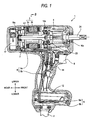
- FIG. 1 shows the impact driver according to the embodiment.
- directions of upper, lower, forward and rear will be explained as being coincident with the directions of upper, lower, forward and rear shown in Fig. 1 , respectively.
- the impact driver 1 performs a fastening procedure for fastening a screw, a nut, a bolt etc.
- a motor 3 is driven by electric power supplied via a power supply cable 2 from the outside, and then the motor 3 drives an oil pulse unit 4 to apply a rotation force and an impact force to the main shaft 24 of the oil pulse unit 4 to thereby continuously/intermittently transmit a rotation striking force to a not-shown tip tool such as a driver bit, a hexagonal socket etc.
- the electric power supplied to the power supply cable 2 is a DC or an AC of 100 volt, for example.
- a not-shown rectifier is provided within the impact driver 1 to convert the AC into the DC and to supply the converted DC to the driving circuit for the motor.
- the motor 3 is a brushless DC motor which includes a rotor 3b having permanent magnets on the inner periphery side thereof and a stator 3a having a winding wound around an iron core on the outer periphery side thereof.
- a housing 6 includes a body part 6a and a handle part 6b integrally formed with each other. The motor is housed within the cylindrical body part 6a so that the rotation shaft thereof is rotatably fixed by two bearings 10a, 10b.
- the housing 6 is formed of plastics etc.
- a driving circuit board 7 for driving the motor 3 is disposed on the rear side of the motor 3.
- An inverter circuit configured by semiconductor elements such as FETs and rotation position detection elements 42 such as hall elements or hall ICs for detecting the rotation positions of the rotor 3b are disposed on this circuit board.
- a cooling fan unit 17 for cooling is provided on the rearmost side of the body part 6a.
- the handle part 6b extends beneath from the body part 6a about orthogonally with respect to the longitudinal direction of the body part 6a.
- a trigger switch 8 is disposed around a portion where the handle part 6b is attached to the body part 6a.
- a switch circuit board 14 provided beneath the trigger switch transmits a signal corresponding to the pulling amount of the trigger switch 8 to a motor control board 9a.
- Two control boards 9, that is, the motor control board 9a and a rotation position detection board 9b, are provided on the lower side of the handle part 6b.
- the motor control board 9a is provided with an impact sensor 12 for detecting a striking impact at the oil pulse unit 4.
- the striking impact can be detected from the output of the impact sensor 12.
- the striking impact at the oil pulse unit 4 may be detected based on a current flowing through the motor. In this case, the unit that detects the current flowing through the motor may be functioning as the impact detection unit.
- the oil pulse unit 4 is housed within the body part 6a of the housing 6.
- a liner plate 23 on the rear side and the main shaft 24 on the front side are provided.
- the liner plate 23 is directly coupled to the rotation shaft of the motor 3, and the main shaft 24 acts as the output shaft of the impact driver 1.
- the trigger switch 8 is pulled to thereby start the motor 3, the rotation force of the motor 3 is transmitted to the oil pulse unit 4.
- Oil is filled within the oil pulse unit 4.
- the main shaft 24 rotates almost synchronously with the rotation of the motor 3 only against the drag of the oil.
- the oil pulse unit 4 When a large load is applied to the main shaft 24, the main shaft 24 stops the rotation, while an outer-peripheral liner 21 fixed to the liner plate 23 continues to rotate.
- the oil pulse unit 4 generates a spiry strong torque and thereby transmits a large fastening torque to the main shaft 24 at a position where the oil is sealed at every one revolution.
- similar striking operations are repeated for several times to thereby fasten a fastening subject with a set torque.
- the main shaft 24 is rotatably supported by the body part 6a of the housing 6 through a bearing 10c.
- a ball bearing is exemplified as the bearing 10c in this embodiment, another bearing such as a needle bearing may be used in place thereof.
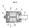
- Fig. 2 is an enlarged sectional diagram of the oil pulse unit 4 of the impact driver shown in Fig. 1 .
- the oil pulse unit 4 is mainly configured by two portions, that is, a driving part rotating synchronously with the motor 3 and an output part rotating synchronously with the main shaft 24 attached with the tip tool.
- the driving part includes the liner plate 23 directly coupled to the rotation shaft of the motor 3, a liner 21 having a cylinder-like outer periphery fixed to the liner plate 23 and a lower plate 22. One end of the liner 21 is fixed to the outer periphery of the liner plate 23, and the other end forwardly extends.
- the output part includes the main shaft 24 and blades 25a, 25b. On the outer circumferential side of the main shaft 24, grooves are formed 24 with the interval of 180 degrees. The blades 25a, 25b are attached to the grooves on the main shaft 24 via springs, respectively.
- the main shaft 24 is inserted into the lower plate 22 and held within a closed space defined by the liner 21, the liner plate 23 and the lower plate 22 so as to be rotatable therein.
- Oil (operation oil) for generating the torque is filled within the closed space.
- An O-ring 30 is provided between the lower plate 22 and the main shaft 24, and also an O-ring 29 is provided between the liner 21 and the liner plate 23, thereby securing the sealability.
- the liner 21 is provided with a relief valve for flowing the oil form the high-pressure side to the low-pressure side, so that the oil pressure (fastening torque) is adjusted.
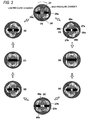
- Fig. 3 is a sectional diagram taken along a line A-A in Fig. 2 showing the one revolution motion of the oil pulse unit 4 in eight steps.
- a liner chamber having four areas is formed as shown in (1) of Fig. 3 .
- the blades 25a, 25b are respectively fitted via the springs into the opposed two grooves formed on the outer circumferential side of the main shaft 24, whereby the blades 25a, 25b are radially urged to abut against the inner surface of the liner 21.
- Two protruded seal surfaces 26a, 26b extending to the axis direction are provided on the outer peripheral surface of the main shaft 24 between the blades 25a, 25b.
- Protruded seal surfaces 27a, 27b and protruded parts 28a, 28b are formed on the inner peripheral surface of the liner 21 so as to have a mountain-like shape, respectively.
- the inner space of the liner 21 is divided into two high-pressure chambers and two low-pressure chambers.
- An instantaneous strong rotation force is generated at the main shaft 24 due to a pressure difference between the high-pressure chamber and the low-pressure chamber.
- FIG. 3 shows states where the liner 21 rotates by one revolution relatively with respect to the main shaft 24.
- the trigger switch 8 When the trigger switch 8 is pulled, the motor 3 rotates and so the liner 21 rotates synchronously with the motor.
- the liner plate 23 is directly coupled to the rotation shaft of the motor 3 to rotate in the same speed therewith.
- the liner plate 23 may be coupled to the motor 3 via a speed reduction mechanism or a deceleration mechanism.
- the main shaft 24 rotates almost synchronously with the rotation of the motor 3 only against the drag of the oil.
- the central main shaft 24 stops the rotation and only the outer-peripheral liner 21 continues to rotate.
- Fig. 3 shows the states where only the liner 21 rotates.
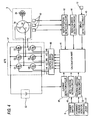
- Fig. 4 shows a block configuration of the driving control system of the motor 3.
- the motor 3 is configured by a three-phase brushless DC motor.
- the brushless DC motor is an inner rotor type and includes a rotor 3b having the plural permanent magnets of pairs of N and S poles, a stator 3a having the three-phase stator windings U, V, W of the star-connection, and the three rotation position detection elements 42 disposed with the interval of a predetermined angle, for example, 60 degrees along the circumferential direction so as to detect the rotation position of the rotor 3b.
- the directions and the conduction times of the currents flowing into the stator windings U, V, W are controlled based on position detection signals from these rotation position detection elements 42.
- the inverter circuit 47 includes six switching elements Q1 to Q6 such as FETs coupled in a three-phase bridge fashion.
- the gates of the six switching elements Q1 to Q6 coupled in the bridge fashion are coupled to a control signal output circuit 46.
- the drains or sources of the six switching elements Q1 to Q6 are coupled to the star-connected stator windings U, V, W.
- the six switching elements Q1 to Q6 perform the switching operation in accordance with switching element drive signals (drive signals H1 to H6) inputted from the control signal output circuit 46 to thereby convert the voltage applied from a DC power supply 52 to the inverter circuit 47 into voltages Vu, Vv, Vw of three-phases (U-phase, V-phase and W-phase) and apply these voltages to the stator windings U, V, W, respectively.
- the DC power supply 52 may be a detachable secondary battery.
- the drive signals for the three switching elements Q4, Q5, Q6 on the negative power supply side are supplied as pulse width modulation signals (PWM signals) H4, H5, H6, respectively.
- a calculation part 41 changes the pulse widths (duty ratios) of the PWM signals in accordance with the detection signal of an apply voltage setting circuit 49 based on the operation amount (stroke) of the trigger switch 8, to thereby adjust an amount of the power supplied to the motor 3 to control the start/stop and the rotation speed of the motor 3.
- the PWM signals are supplied to the switching elements Q1 to Q3 on the positive power supply side of the inverter circuit 47 or the switching elements Q4 to Q6 on the negative power supply side to thereby switch the switching elements Q1 to Q3 or the switching elements Q4 to Q6 at a high speed to thereby control the power to be supplied to the stator windings U, V, W from the DC power supply.
- the PWM signals are supplied to the switching elements Q4 to Q6 on the negative power supply side.
- the impact driver 1 is provided with a forward/reverse rotation switching lever 51 for switching the rotation direction of the motor 3.
- a rotation direction setting circuit 50 sends a control signal for switching the rotation direction of the motor 3 to the calculation part 41 (control unit) when the forward/reverse rotation switching lever 51 is changed.
- the calculation part 41 (control unit) includes a central processing unit (CPU) for outputting the drive signals based on a processing program and data, a ROM for storing the processing program and control data, a RAM for temporarily storing data, and a timer etc.
- a rotation speed detection circuit 44 receives a signal from a rotor position detection circuit 43 to detect the rotation speed of the motor 3, and outputs the detection value to the calculation part 41.
- the rotor position detection circuit 43 outputs a position signal representing the rotation position of the motor 3 based on the signals from the rotation position detection elements 42.
- An impact detection circuit 45 detects a striking impact caused by a striking operation in accordance with the signal from the impact sensor 12 and outputs the detection value to the calculation part 41.
- the calculation part 41 (control unit) outputs the drive signals for alternately switching the predetermined switching elements Q1 to Q6 based on the output signals from the rotation direction setting circuit 50 and the rotor position detection circuit 43 and outputs the drive signals to the control signal output circuit 46.
- the current is alternately supplied to the predetermined windings of the stator windings U, V, W to thereby rotate the rotor 3b in the set rotation direction.
- the drive signals applied to the switching elements Q4 to Q6 on the negative power supply side of the inverter circuit 47 are outputted as the PWM modulation signals based on the output control signal from the apply voltage setting circuit 49.
- the current supplied to the motor 3 is measured by a current detection circuit 48 and the measured value is feedbacked to the calculation part 41, whereby the drive signals are adjusted so that the set drive power is applied to the motor.
- the PWM signals may be supplied to the switching elements Q1 to Q3 on the positive power supply side.
- Fig. 5 exemplifies a relation between the output waveforms of the rotor position detection circuit 43 and the rotation position signal of the motor 3. Since the motor 3 is a three-phase two-pole motor, the three rotation position detection elements 42 for the U-, V- and W-phases are provided with an interval of 60 degrees. Rectangular waveforms 61 to 63 are obtained by subjecting the output signals of the rotation position detection elements 42 to the analog-to-digital (A/D) conversion processing. Each of the rectangular waveforms is changed between a low level and a high level alternately at every 90-degrees rotation of the rotor 3b.
- A/D analog-to-digital
- a rectangular waveform 64 is a narrow pulse generated at every 30-degrees rotation of the rotor 3b in response to the rising edge or the falling edge of the rectangular waveforms 61 to 63 for the U-, V- and W-phases.
- This rectangular waveform 64 is used as the position detection pulse, and the twelve position detection pulses appear during 360-degrees rotation of the rotor 3b.
- the input portion (liner plate 23) is coupled to the rotation shaft of the motor 3.
- the liner 21 is synchronously rotated with the rotor 3b to have the same rotation angle therewith.
- the rotation of the liner 21 is not completely synchronized with the rotation of the main shaft 24 as shown in Fig. 3 .
- the liner 21 (the rotor 3b) will rotate by "360 degrees + the given angle" until reaching the next striking position.
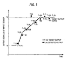
- Fig. 6 exemplifies the target output and the actual output of the impact sensor 12 until the actual output reaches the final target output after the oil pulse unit 4 starts the striking operation.
- the striking impact corresponds to the output value of the impact sensor 12.
- the number of times of the striking operation is represented with the numerals in parenthesis.
- the ordinate represents the output signal (A/m2 or volt) of the impact sensor 12 and the abscissa represents the time (msec).
- the liner 21 and the main shaft 24 When performing the fastening operation by the impact driver 1, the liner 21 and the main shaft 24 almost synchronously rotate until the seat surface of the fastening-subject bolt is seated, and the main shaft 24 is almost stopped while only the liner 21 rotates when a load is applied to the tip tool. Then, the fastening force is intermittently transmitted to the main shaft 24 by the oil pulse unit 4, thereby performing the striking operation.
- the rotation of the motor 3 is controlled so that the output of the impact sensor 12 becomes the target output.
- the detected output is T(1).
- the second striking is performed with the next target output Tr(2) calculated based on the output T(1).
- the third and fourth striking operations are performed sequentially while gradually increasing the target output Tr(n), and the detected outputs are T(3) and T(4).
- the striking force may become large due to any reason.
- the fourth striking force becomes large so that the fourth output T(4) exceeds a cut output Tc.
- the peak output becomes large while the striking period becomes short.
- the motor 3 will stop the rotation since it is determined that the fastening operation is completed.
- the striking operation can be continued without stopping the motor 3 by determining whether the normal fastening operation is completed based on whether the main shaft 24 rotates more than a predetermined angle at the striking operation.
- the angular sensor is not provided at the main shaft 24, the rotation angle in the striking operation can not be directly obtained to determine whether the fastening operation is completed.
- the impact driver 1 is configured to not immediately stop the motor 3 even if the output T(4) exceeds the cut output Tc and to perform an additional striking (called a "confirmation striking" in this specification) for the confirmation.
- the target output Tr(5) is set based on the previous target output Tr(4), not the previous output T(4).
- the target output Tr(5) is an output value almost between Tr(4) and Tr (6) and does not exceed the cut output Tc.
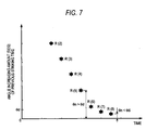
- Fig. 7 exemplifies an angle increasing amount R(n) of the main shaft 24 (tip tool) at the previous striking operation by the oil pulse unit 4.
- the fastening operation can be continued, and the sixth and seventh striking operations can be continuously performed as shown in Fig. 6 .
- the seventh striking operation although the output T(7) exceeds the cut output Tc, the motor 3 is not stopped immediately but the striking (eighth striking) for the confirmation is performed. And, it can be confirmed that the main shaft 24 rotates only by R(8) degrees at the previous striking (seventh striking) by performing the eighth striking. That is, it can be confirmed that the rotation angle of the main shaft 24 is smaller than the threshold value ⁇ d representing the completion of the striking operation at the previous striking, the motor 3 is stopped when the eighth striking is completed.
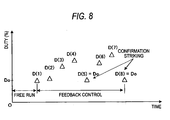
- Fig. 8 exemplifies the duty ratio of the PWM signal supplied to the inverter circuit 47 at each striking operation shown in Figs. 6 and 7 .
- the rotation control of the motor 3 is performed with a predetermined duty ratio D0 until the first striking is performed (free run), and the rotation control of the motor is performed with duty ratios determined by the following expression after the first striking is performed, that is, the feedback control is performed.
- the duty ratios are set to satisfy the relation of D(4) > D(3) > D(2) and D(7) >D(6) in order to gradually increase the striking force as the striking number of times increases.
- each of the fifth and eighth strikings is the confirmation striking for confirming whether or not the fastening operation is completed, each of the fifth and eighth strikings is performed with the duty ratio (for example, the duty ratio D0) sufficiently smaller than the duty ratio of the previous striking.
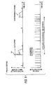
- Fig. 9 exemplifies a relation between the peak output and the position detection pulses in a pseudo seating state like the fourth striking shown in Fig. 6 .
- a peak output 101 exceeds the cut output Tc.
- the liner 21 of the oil pulse unit 4 rotates by a large angle (60 degrees, for example) so that the two or three position detection pulses appear until the peak output 101 reduces to 0.
- the liner 21 rotates together with the main shaft 24 at the striking operation (this phenomenon is called "co-rotation"). Since the 60-degrees co-rotation appears in the fourth striking, it can be determined that the state after the fourth striking is not the normal state (a state where the fastening operation can be performed scarcely) at the time of the completion of the fastening operation. Since the position detection pulse appears at every 30 degrees, the co-rotation may be detected with an angular error of less than ⁇ 30 degrees. Such the degree of error is sufficient for determining whether or not the fastening operation is completed.
- Fig. 10 exemplifies a relation between the peak output and the position detection pulses in an actual seating state like the seventh striking shown in Fig. 6 .
- a peak output 111 exceeding the cut output Tc is generated.
- the position detection pulse does not appear until the peak output 111 reduces to 0.
- the 12 position detection pulses appear until the next confirmation striking, it can be confirmed that the rotation angle of the co-rotation at the seventh striking operation is almost 0.
- the state after the seventh striking is the state where the fastening operation of a bolt is completed and a further fastening operation can not be performed.
- the motor 3 is started when the user pulls the trigger switch 8 (step 120).
- the rotation speed of the motor 3 changes in accordance with the pulling amount of the trigger switch 8
- the liner 21 of the oil pulse unit 4 rotates almost synchronously with the main shaft 24 without causing any striking until a bolt is seated.
- the main shaft 24 of the oil pulse unit 4 stops the rotation and only the liner 21 continues the rotation.
- the liner 21 reaches the striking position explained in Fig. 3 , a striking force due to the impact pulse is generated at the main shaft 24 to perform the first striking (step 121).
- the calculation part 41 (control unit) counts the number of the striking performed in step 121 and measures the co-rotation angle according to the method explained in Figs. 9 and 10 (step 122). In the first striking, since there is no previous striking, the number of the position detection pulses appeared from the start of the motor 3 to the first striking is counted. Next, the calculation part 41 determines whether or not this striking is the first striking. The process proceeds to step 128 when this striking is the first striking, while the process proceeds to step 124 when this striking is the second or succeeding striking.
- a free run angle is obtained based on the number of the position detection pulses appeared from the start of the motor 3 to the first striking, and it is determined whether or not the obtained angle is equal to or smaller than a set angle for determining a double fastening.
- the double fastening is to perform a fastening again by pulling the trigger switch 8 by abutting the tip tool against the fastening subject such as a bolt. In this case, the striking operation is performed immediately at the next striking position during the rotation of the oil pulse unit 4.
- the double fastening is performed when the striking operation is started at the rotation angle from the start of the motor 3 which is equal to or smaller than the set angle, whereby the calculation part 41 stops the rotation of the motor 3 to complete the processing (step 130).
- the processing proceeds to step 124.
- step 124 It is determined in step 124 whether or not the peak output exceeds the cut output Tc.
- the feedback control of the motor 3 is performed by using the detected output value (step 127) and the process returns to step 121.
- the duty ratio D(n) for the feedback control is calculated from the detected output value.
- the duty ratio is set to the initial duty ratio D0 to thereby perform the confirmation striking (step 125).
- the confirmation striking it is determined whether or not the rotation angle (co-rotation angle) until this striking is equal to or smaller than the set angle (step 126).
- step 129 When it is determined that the rotation angle is larger than the set angle, the process proceeds to step 127 since this state is the pseudo seating state explained in Fig. 9 . In contrast, when it is determined that the rotation angle is equal to or smaller than the set angle in step 126, since it can be confirmed that this state is the actual seating state explained in Fig. 10 , the calculation part 41 stops the rotation of the motor (step 129).
- the additional striking with a small striking force is performed as the confirmation striking to detect the rotation angle of the output shaft until the next striking is detected, whereby whether or not the fastening operation is performed correctly can be surely confirmed.
- the invention is not limited thereto, and various modifications may be made within the scope of the invention.
- the oil pulse unit is exemplified as the impact unit
- the invention is not limited thereto, and the invention may be applied in the similar manner not only to the rotary striking tool using the oil pulse unit but also to the rotary striking tool using an impact mechanism having a mechanical hummer and an anvil.
- the brushless DC motor is exemplified as the driving source of the impact mechanism, the invention may be applied in the similar manner to the rotary striking tool using a brush DC motor.
- the invention may be applied in the similar manner to the rotary striking tool using an air motor as the driving source.
- the driving source having no detection mechanism for the motor rotation angle such as the brush DC motor or the air motor
- a sensor for detecting the motor rotation angle or a sensor for detecting the rotation angle of the output shaft to which the tip tool is fixed may be used.
Landscapes
- Engineering & Computer Science (AREA)
- Mechanical Engineering (AREA)
- Details Of Spanners, Wrenches, And Screw Drivers And Accessories (AREA)
- Percussive Tools And Related Accessories (AREA)
Description
- An aspect of the present invention relates to a rotary striking tool which is driven and rotated by a motor to thereby fasten a fastening member such as a screw or a bolt by using an intermittent striking force.
- As a rotary striking tool (driving tool), an impact tool which fastens a screw or a bolt etc. by applying a rotation force or a rotational-direction striking force is known.
JP-2005-305578-A JP-2005-305578-A - The oil pulse tool has a feature that the level of the operation sound is low since metal parts never contact to each other. In the oil pulse tool, a motor is used as a power source for driving an oil pulse unit, and the rotation shaft of the motor is directly coupled to the oil pulse unit. When a trigger switch for operating the oil pulse tool is pulled, a driving electric power is supplied to the motor. The rotation speed of the motor is controlled by changing the driving force of the motor in response to the pulling amount of the trigger switch. When the oil pulse unit generates a pulse torque, a strong striking torque is transmitted to a tip tool, whereby a torque sensor detects the peak torque of the output shaft at every striking operation. An angular sensor is provided at the output shaft to detect the rotation angle of the output shaft, whereby the peak torque value is controlled to approach a target torque value in accordance with a difference between the previously-set target curve of the peak torque values from the fastening start timing to the fastening completion timing and the measured peak torque value.
- In the sold oil pulse tool, an increasing amount of the rotation angle at each striking is calculated based on an angle value obtained from an angular sensor. When the increasing amount of the rotation angle is larger than a reference value (seating state determination value), it is determined that the fastening operation is not completed yet to thereby continue the striking operation even if a peak torque exceeds a reference value (fastening operation completion determination value). The motor is stopped when two conditions are satisfied that the peak value exceeds the fastening operation completion determination value and the increasing amount of the rotation angle is smaller than the seating state determination value. In order to surely control the fastening operation completion state based on the two conditions of the peak torque and the increasing amount of the rotation angle, it is necessary to provide a torque sensor and an angular sensor at the output shaft of the oil pulse tool, so that a rotary transformer is required in order to transmit and receive signals to and from these sensors. As a result, the impact tool is enlarged to provide the angular sensor and the rotary transformer etc., whereby electric wiring becomes complicated and the tool becomes expensive.
-
JP 2008 213089 A claim 1. - One object of the invention is to provide a rotary striking tool which can accurately detect the rotation angle of an output shaft at the striking operation even if an angular sensor is not provided at the output shaft.
- Another object of the invention is to provide the rotary striking tool which can surely perform the fastening operation up to a prescribed torque even if the angular sensor or a torque sensor is not provided at the output shaft.
- A still another object of the invention is to provide the rotary striking tool unit in which a completion of a fastening operation is confirmed by the output of an impact sensor and the rotation angle of a motor to thereby avoid the fastening failure of the fastening member.
- According to an aspect of the present invention, there is provided a rotary striking tool having the features of
claim 1. - According to the above configuration, when it is determined that the output value detected by the impact detection unit reaches the prescribed value, the impact unit performs the confirmation striking and detects the rotation angle of the output shaft through the confirmation striking. When the detected rotation angle is equal to or smaller than the predetermined angle, since the fastening operation is completed, a fastening insufficient state can be effectively prevented from being caused. In contrast, when the detected rotation angle is larger than the predetermined angle, since the fastening operation is continued, the fastening operation can be completed surely.
- When the rotation of the motor is controlled so that the force of the confirmation striking is smaller than the force of the previous striking, a fastening member can be prevented from being excessively fastened in the confirmation striking.
- The motor may be a brushless DC motor. Rotation position detection elements may be provided at the brushless DC motor. And, the rotation angle may be calculated based on outputs of the rotation position detection elements.
- The rotation angle may be calculated based on variation in the outputs of the rotation position detection elements during a period from a previous striking to a next striking.
- The brushless DC motor may include a rotor having plural permanent magnets of pairs of N and S poles. And, the position detection elements may be hall elements or hall ICs which are provided at a predetermined interval so as to face the permanent magnets.
- The confirmation striking may be performed in a state where a duty ratio of a signal supplied to an inverter circuit for supplying a driving current to the brushless DC motor is reduced.
- According to the above configuration, the brushless DC motor is used as the motor, and the rotation angle of the output shaft is indirectly (not directly) detected/calculated by using the outputs of the rotation position detection elements provided at the brushless DC motor. Since it is not necessary to provide a sensor for directly detecting the rotation angle at the output shaft to which the tip tool is attached, the size of the rotary striking tool can be made small and the manufacturing cost thereof can be reduced.
- Since the rotation angle is calculated based on the position detection pulses appearing from the previous striking to the next striking, it is possible to calculate how much the output shaft rotated at the previous striking.
- The position detection elements are configured by the hall elements or the hall ICs which are disposed with a predetermined interval so as to oppose to the permanent magnets. The operation of the invention can be realized only by appropriately controlling the calculation part without changing the configuration of the existing motor.
- The confirmation striking is performed in a state that the duty ratio of the signal supplied to the inverter circuit for supplying the driving current to the brushless DC motor is reduced. Thus, the fastening member is prevented from being excessively fastened in the confirmation striking.
- The aforesaid and other objects and new features of the invention will be apparent from the following description of the specification and accompanying drawings.
-
-
Fig. 1 is a sectional diagram of an impact driver according to an embodiment. -
Fig. 2 is an enlarged sectional diagram of anoil pulse unit 4 in the impact driver shown inFig. 1 . -
Fig. 3 is sectional diagram taken along a line A-A inFig. 2 showing the one revolution motion of theoil pulse unit 4 in eight steps. -
Fig. 4 shows a block configuration of the driving control system of amotor 3 according to the embodiment. -
Fig. 5 exemplifies a relation between the output waveforms of a rotorposition detection circuit 43 and the rotation position signal of themotor 3. -
Fig. 6 exemplifies the target output and the actual output of animpact sensor 12 until the actual output reaches the final target output after theoil pulse unit 4 starts the striking operation. -
Fig. 7 exemplifies an increasing amount of a fastening angle from the previous striking to the current striking performed by theoil pulse unit 4. -
Fig. 8 exemplifies the duty ratio of a PWM signal supplied to aninverter circuit 47 at each striking operation shown inFigs. 6 and7 . -
Fig. 9 exemplifies a relation between a peak output and position detection pulses in a pseudo seating state like the fourth striking shown inFig. 6 . -
Fig. 10 exemplifies a relation between the peak output and the position detection pulses in an actual seating state like the seventh striking shown inFig. 6 . -
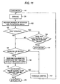
Fig. 11 exemplifies a control procedure of a striking operation in a rotary striking tool according to the embodiment. - Hereinafter, the embodiment will be explained with reference to drawings. In this embodiment, an impact driver using an oil pulse unit is exemplified as a rotary striking tool.
Fig. 1 shows the impact driver according to the embodiment. In the specification, directions of upper, lower, forward and rear will be explained as being coincident with the directions of upper, lower, forward and rear shown inFig. 1 , respectively. - The
impact driver 1 performs a fastening procedure for fastening a screw, a nut, a bolt etc. In the fastening procedure, amotor 3 is driven by electric power supplied via apower supply cable 2 from the outside, and then themotor 3 drives anoil pulse unit 4 to apply a rotation force and an impact force to themain shaft 24 of theoil pulse unit 4 to thereby continuously/intermittently transmit a rotation striking force to a not-shown tip tool such as a driver bit, a hexagonal socket etc. - The electric power supplied to the
power supply cable 2 is a DC or an AC of 100 volt, for example. In the case of AC, a not-shown rectifier is provided within theimpact driver 1 to convert the AC into the DC and to supply the converted DC to the driving circuit for the motor. Themotor 3 is a brushless DC motor which includes arotor 3b having permanent magnets on the inner periphery side thereof and astator 3a having a winding wound around an iron core on the outer periphery side thereof. Ahousing 6 includes abody part 6a and ahandle part 6b integrally formed with each other. The motor is housed within thecylindrical body part 6a so that the rotation shaft thereof is rotatably fixed by twobearings housing 6 is formed of plastics etc. A drivingcircuit board 7 for driving themotor 3 is disposed on the rear side of themotor 3. An inverter circuit configured by semiconductor elements such as FETs and rotationposition detection elements 42 such as hall elements or hall ICs for detecting the rotation positions of therotor 3b are disposed on this circuit board. A coolingfan unit 17 for cooling is provided on the rearmost side of thebody part 6a. - In the
housing 6, thehandle part 6b extends beneath from thebody part 6a about orthogonally with respect to the longitudinal direction of thebody part 6a. Atrigger switch 8 is disposed around a portion where thehandle part 6b is attached to thebody part 6a. Aswitch circuit board 14 provided beneath the trigger switch transmits a signal corresponding to the pulling amount of thetrigger switch 8 to amotor control board 9a. Twocontrol boards 9, that is, themotor control board 9a and a rotationposition detection board 9b, are provided on the lower side of thehandle part 6b. Themotor control board 9a is provided with animpact sensor 12 for detecting a striking impact at theoil pulse unit 4. The striking impact can be detected from the output of theimpact sensor 12. Instead of providing theimpact sensor 12 as an impact detection unit, the striking impact at theoil pulse unit 4 may be detected based on a current flowing through the motor. In this case, the unit that detects the current flowing through the motor may be functioning as the impact detection unit. - The
oil pulse unit 4 is housed within thebody part 6a of thehousing 6. In theoil pulse unit 4, aliner plate 23 on the rear side and themain shaft 24 on the front side are provided. Theliner plate 23 is directly coupled to the rotation shaft of themotor 3, and themain shaft 24 acts as the output shaft of theimpact driver 1. When thetrigger switch 8 is pulled to thereby start themotor 3, the rotation force of themotor 3 is transmitted to theoil pulse unit 4. Oil is filled within theoil pulse unit 4. When no load is applied to themain shaft 24 or an applied load is small, themain shaft 24 rotates almost synchronously with the rotation of themotor 3 only against the drag of the oil. When a large load is applied to themain shaft 24, themain shaft 24 stops the rotation, while an outer-peripheral liner 21 fixed to theliner plate 23 continues to rotate. Theoil pulse unit 4 generates a spiry strong torque and thereby transmits a large fastening torque to themain shaft 24 at a position where the oil is sealed at every one revolution. Hereinafter, similar striking operations are repeated for several times to thereby fasten a fastening subject with a set torque. Themain shaft 24 is rotatably supported by thebody part 6a of thehousing 6 through abearing 10c. Although a ball bearing is exemplified as thebearing 10c in this embodiment, another bearing such as a needle bearing may be used in place thereof. -
Fig. 2 is an enlarged sectional diagram of theoil pulse unit 4 of the impact driver shown inFig. 1 . Theoil pulse unit 4 is mainly configured by two portions, that is, a driving part rotating synchronously with themotor 3 and an output part rotating synchronously with themain shaft 24 attached with the tip tool. The driving part includes theliner plate 23 directly coupled to the rotation shaft of themotor 3, aliner 21 having a cylinder-like outer periphery fixed to theliner plate 23 and alower plate 22. One end of theliner 21 is fixed to the outer periphery of theliner plate 23, and the other end forwardly extends. The output part includes themain shaft 24 andblades main shaft 24, grooves are formed 24 with the interval of 180 degrees. Theblades main shaft 24 via springs, respectively. - The
main shaft 24 is inserted into thelower plate 22 and held within a closed space defined by theliner 21, theliner plate 23 and thelower plate 22 so as to be rotatable therein. Oil (operation oil) for generating the torque is filled within the closed space. An O-ring 30 is provided between thelower plate 22 and themain shaft 24, and also an O-ring 29 is provided between theliner 21 and theliner plate 23, thereby securing the sealability. Although not shown, theliner 21 is provided with a relief valve for flowing the oil form the high-pressure side to the low-pressure side, so that the oil pressure (fastening torque) is adjusted. -
Fig. 3 is a sectional diagram taken along a line A-A inFig. 2 showing the one revolution motion of theoil pulse unit 4 in eight steps. Within theliner 21, a liner chamber having four areas is formed as shown in (1) ofFig. 3 . Theblades main shaft 24, whereby theblades liner 21. Two protrudedseal surfaces main shaft 24 between theblades Protruded seal surfaces parts liner 21 so as to have a mountain-like shape, respectively. - In the fastening operation of a bolt by using the
impact driver 1, when the seat surface of the fastening-subject bolt is seated, a load is applied to themain shaft 24, whereby themain shaft 24 and theblades liner 21 continues to rotate. Since theliner 21 rotates with respect to themain shaft 24, an impact pulse is generated at each revolution of the liner. When the impact pulse is generated within theimpact driver 1, the protrudedseal surface 27a formed on the inner peripheral surface of theliner 21 is made contact with the protrudedseal surface 26a formed on the outer peripheral surface of themain shaft 24. Simultaneously, the protrudedseal surface 27b contacts with the protrudedseal surface 26b. In this manner, since a pair of the protrudedseal surfaces seal surfaces liner 21 is divided into two high-pressure chambers and two low-pressure chambers. An instantaneous strong rotation force is generated at themain shaft 24 due to a pressure difference between the high-pressure chamber and the low-pressure chamber. - Next, the operation procedure of the
oil pulse unit 4 will be explained. (1) to (8) ofFig. 3 show states where theliner 21 rotates by one revolution relatively with respect to themain shaft 24. When thetrigger switch 8 is pulled, themotor 3 rotates and so theliner 21 rotates synchronously with the motor. In this embodiment, theliner plate 23 is directly coupled to the rotation shaft of themotor 3 to rotate in the same speed therewith. However, theliner plate 23 may be coupled to themotor 3 via a speed reduction mechanism or a deceleration mechanism. When no load is applied to themain shaft 24 or an applied load is small, themain shaft 24 rotates almost synchronously with the rotation of themotor 3 only against the drag of the oil. When a large load is applied to the tip tool, the centralmain shaft 24 stops the rotation and only the outer-peripheral liner 21 continues to rotate.Fig. 3 shows the states where only theliner 21 rotates. - (1) of
Fig. 3 shows the position in which a striking force is generated at themain shaft 24 due to the impact pulse. The position shown in (1) represents a "position for hermetically sealing the oil" appearing once during one revolution. In this case, theprotruded seal surfaces seal surfaces blades parts main shaft 24, whereby the inner space of theliner 21 is partitioned into four chambers, that is, the two high-pressure chambers and the two low-pressure chambers.
The "high-pressure" and the "low-pressure" represent the pressure of the oil within the inner space. When theliner 21 rotates in accordance with the rotation of themotor 3, since the capacity of the high-pressure chamber reduces, the oil therein is compressed to thereby instantaneously generate a high pressure and push the blade 25 to the low-pressure chamber side. As a result, a rotation force instantaneously acts on themain shaft 24 via theblades blades Fig. 3 is called a "striking position" in this specification - (2) of
Fig. 3 shows a state where theliner 21 rotates by 45 degrees from the striking position. When theliner 21 passes the striking position shown in (1), since the abutment between theprotruded seal surface protruded seal surfaces blades parts liner 21 divided into the four chambers is released. Thus, since the oil flows into the respective chambers, the rotation torque is not generated and theliner 21 further rotates due to the rotation of themotor 3. - (3) of
Fig. 3 shows a state where theliner 21 rotates by 90 degrees from the striking position. In this state, theblades seal surfaces main shaft 24, respectively. Thus, since there is no influence of the oil pressure and the rotation torque is not generated, theliner 21 continues to rotate. - (4) of
Fig. 3 shows a state where theliner 21 rotates by 135 degrees from the striking position. In this state, since the respective areas in theliner 21 are communicated to each other, no pressure difference is caused thereamong, so that no rotation torque is generated at themain shaft 24. - (5) of
Fig. 3 shows a state where theliner 21 rotates by 180 degrees from the striking position. Here, theprotruded seal surfaces main shaft 24 with respect to the axis thereof. Therefore, in this position, theprotruded seal surfaces protruded seal surfaces protruded seal surfaces liner 21 with respect to the axis of themain shaft 24. Thus, in this position, since the main shaft is scarcely influenced by the oil, the rotation torque is also scarcely generated. Since the oil filled within the inner space has viscosity and a small high-pressure chamber is formed when the protrudedseal surface seal surface - The states of (6) to (8) of
Fig. 3 are almost the same as (2) to (4), respectively, and the rotation torque is scarcely generated in these states. When theliner 21 further rotates from the state of (8), theliner 21 returns to the state of (1). Thus, theprotruded seal surfaces seal surfaces blades parts main shaft 24, whereby the inner space of theliner 21 is partitioned into the two high-pressure chambers and the two low-pressure chambers and hence a large rotation torque is generated at themain shaft 24. - Next, the configuration and function of the driving control system of the
motor 3 will be explained with reference toFig. 4. Fig. 4 shows a block configuration of the driving control system of themotor 3. In this embodiment, themotor 3 is configured by a three-phase brushless DC motor. The brushless DC motor is an inner rotor type and includes arotor 3b having the plural permanent magnets of pairs of N and S poles, astator 3a having the three-phase stator windings U, V, W of the star-connection, and the three rotationposition detection elements 42 disposed with the interval of a predetermined angle, for example, 60 degrees along the circumferential direction so as to detect the rotation position of therotor 3b. The directions and the conduction times of the currents flowing into the stator windings U, V, W are controlled based on position detection signals from these rotationposition detection elements 42. - The
inverter circuit 47 includes six switching elements Q1 to Q6 such as FETs coupled in a three-phase bridge fashion. The gates of the six switching elements Q1 to Q6 coupled in the bridge fashion are coupled to a controlsignal output circuit 46. The drains or sources of the six switching elements Q1 to Q6 are coupled to the star-connected stator windings U, V, W. Thus, the six switching elements Q1 to Q6 perform the switching operation in accordance with switching element drive signals (drive signals H1 to H6) inputted from the controlsignal output circuit 46 to thereby convert the voltage applied from aDC power supply 52 to theinverter circuit 47 into voltages Vu, Vv, Vw of three-phases (U-phase, V-phase and W-phase) and apply these voltages to the stator windings U, V, W, respectively. TheDC power supply 52 may be a detachable secondary battery. - Of the switching element drive signals (three-phase signals) for driving the respective gates of the six switching elements Q1 to Q6, the drive signals for the three switching elements Q4, Q5, Q6 on the negative power supply side are supplied as pulse width modulation signals (PWM signals) H4, H5, H6, respectively. A calculation part 41 (control unit) changes the pulse widths (duty ratios) of the PWM signals in accordance with the detection signal of an apply
voltage setting circuit 49 based on the operation amount (stroke) of thetrigger switch 8, to thereby adjust an amount of the power supplied to themotor 3 to control the start/stop and the rotation speed of themotor 3. - The PWM signals are supplied to the switching elements Q1 to Q3 on the positive power supply side of the
inverter circuit 47 or the switching elements Q4 to Q6 on the negative power supply side to thereby switch the switching elements Q1 to Q3 or the switching elements Q4 to Q6 at a high speed to thereby control the power to be supplied to the stator windings U, V, W from the DC power supply. In this embodiment, the PWM signals are supplied to the switching elements Q4 to Q6 on the negative power supply side. Thus, when the pulse widths of the PWM signals are controlled, since the power supplied to the stator windings U, V, W are adjusted, the rotation speed of themotor 3 can be controlled. - The
impact driver 1 is provided with a forward/reverserotation switching lever 51 for switching the rotation direction of themotor 3. A rotationdirection setting circuit 50 sends a control signal for switching the rotation direction of themotor 3 to the calculation part 41 (control unit) when the forward/reverserotation switching lever 51 is changed. Although not shown, the calculation part 41 (control unit) includes a central processing unit (CPU) for outputting the drive signals based on a processing program and data, a ROM for storing the processing program and control data, a RAM for temporarily storing data, and a timer etc. A rotationspeed detection circuit 44 receives a signal from a rotorposition detection circuit 43 to detect the rotation speed of themotor 3, and outputs the detection value to thecalculation part 41. The rotorposition detection circuit 43 outputs a position signal representing the rotation position of themotor 3 based on the signals from the rotationposition detection elements 42. Animpact detection circuit 45 detects a striking impact caused by a striking operation in accordance with the signal from theimpact sensor 12 and outputs the detection value to thecalculation part 41. - The calculation part 41 (control unit) outputs the drive signals for alternately switching the predetermined switching elements Q1 to Q6 based on the output signals from the rotation
direction setting circuit 50 and the rotorposition detection circuit 43 and outputs the drive signals to the controlsignal output circuit 46. Thus, the current is alternately supplied to the predetermined windings of the stator windings U, V, W to thereby rotate therotor 3b in the set rotation direction. In this case, the drive signals applied to the switching elements Q4 to Q6 on the negative power supply side of theinverter circuit 47 are outputted as the PWM modulation signals based on the output control signal from the applyvoltage setting circuit 49. The current supplied to themotor 3 is measured by acurrent detection circuit 48 and the measured value is feedbacked to thecalculation part 41, whereby the drive signals are adjusted so that the set drive power is applied to the motor. The PWM signals may be supplied to the switching elements Q1 to Q3 on the positive power supply side. -
Fig. 5 exemplifies a relation between the output waveforms of the rotorposition detection circuit 43 and the rotation position signal of themotor 3. Since themotor 3 is a three-phase two-pole motor, the three rotationposition detection elements 42 for the U-, V- and W-phases are provided with an interval of 60 degrees.Rectangular waveforms 61 to 63 are obtained by subjecting the output signals of the rotationposition detection elements 42 to the analog-to-digital (A/D) conversion processing. Each of the rectangular waveforms is changed between a low level and a high level alternately at every 90-degrees rotation of therotor 3b. Arectangular waveform 64 is a narrow pulse generated at every 30-degrees rotation of therotor 3b in response to the rising edge or the falling edge of therectangular waveforms 61 to 63 for the U-, V- and W-phases. Thisrectangular waveform 64 is used as the position detection pulse, and the twelve position detection pulses appear during 360-degrees rotation of therotor 3b. InFig. 5 , therectangular waveform 64 becomes the high level at every 360-degrees rotation of therotor 3b from the start point (rotation angle = 0, the position signal "12"), and the twelfth rectangular pulse appears when therotor 3b rotates by 360 degrees with respect to thestator 3a. - In the
oil pulse unit 4 according to the embodiment, the input portion (liner plate 23) is coupled to the rotation shaft of themotor 3. Thus, theliner 21 is synchronously rotated with therotor 3b to have the same rotation angle therewith. The rotation of theliner 21 is not completely synchronized with the rotation of themain shaft 24 as shown inFig. 3 . However, when themain shaft 24 rotates by a given angle in the striking operation, the liner 21 (therotor 3b) will rotate by "360 degrees + the given angle" until reaching the next striking position. -
Fig. 6 exemplifies the target output and the actual output of theimpact sensor 12 until the actual output reaches the final target output after theoil pulse unit 4 starts the striking operation. The striking impact corresponds to the output value of theimpact sensor 12. In the figure, the number of times of the striking operation is represented with the numerals in parenthesis. InFig. 6 , the ordinate represents the output signal (A/m2 or volt) of theimpact sensor 12 and the abscissa represents the time (msec). When performing the fastening operation by theimpact driver 1, theliner 21 and themain shaft 24 almost synchronously rotate until the seat surface of the fastening-subject bolt is seated, and themain shaft 24 is almost stopped while only theliner 21 rotates when a load is applied to the tip tool. Then, the fastening force is intermittently transmitted to themain shaft 24 by theoil pulse unit 4, thereby performing the striking operation. - In the striking operation, the rotation of the
motor 3 is controlled so that the output of theimpact sensor 12 becomes the target output. For example, when the rotation of themotor 3 is controlled so that the target output Tr(1) of the first striking becomes equal to a start output Ts, the detected output is T(1). Next, the second striking is performed with the next target output Tr(2) calculated based on the output T(1). In the similar manner, the third and fourth striking operations are performed sequentially while gradually increasing the target output Tr(n), and the detected outputs are T(3) and T(4). Usually, when there is no failure or no quality variance etc. in the fastening material, such as the bolt or the nut, the detected output T(n) almost coincides with the target output Tr(n) (n = 1, 2, ,,, m). - However, sometimes, the striking force may become large due to any reason. In
Fig. 6 , the fourth striking force becomes large so that the fourth output T(4) exceeds a cut output Tc. For example, when a large reaction force is received from the tip tool, even if a striking energy is not so large, the peak output becomes large while the striking period becomes short. In the impact driver having no rotation angle sensor (as in the related art), when the detected output T(4) exceeds the cut output Tc, themotor 3 will stop the rotation since it is determined that the fastening operation is completed. In the impact driver having an angular sensor at the main shaft 24 (as in the related art), when the detected output T(4) exceeds the cut output Tc, the striking operation can be continued without stopping themotor 3 by determining whether the normal fastening operation is completed based on whether themain shaft 24 rotates more than a predetermined angle at the striking operation. However, when the angular sensor is not provided at themain shaft 24, the rotation angle in the striking operation can not be directly obtained to determine whether the fastening operation is completed. - Thus, the
impact driver 1 according to the embodiment is configured to not immediately stop themotor 3 even if the output T(4) exceeds the cut output Tc and to perform an additional striking (called a "confirmation striking" in this specification) for the confirmation. In the confirmation striking, in the case ofFig. 6 , the target output Tr(5) is set based on the previous target output Tr(4), not the previous output T(4). As a result, the target output Tr(5) is an output value almost between Tr(4) and Tr (6) and does not exceed the cut output Tc.Fig. 7 exemplifies an angle increasing amount R(n) of the main shaft 24 (tip tool) at the previous striking operation by theoil pulse unit 4. The angle increasing amount R(n) inFig. 7 is presented correspondingly with the (n-th) striking timing inFig. 6 . As described above, the liner 21 (therotor 3b) will rotate "360 degrees + the actual rotation angle of themain shaft 24" between the two striking operations. In view of that, the angle increasing amount R(n) can be obtained by using the rotationposition detection elements 42 provided in themotor 3, without providing the angular sensor at themain shaft 24. For example, when it is rotated by "360 degrees + R(5) degrees" between the fourth striking and the fifth striking, themain shaft 24 is rotated by R(5) degrees by the previous striking (fourth striking). As seen fromFig. 7 , by performing the confirmation striking (fifth striking corresponding to T(5) inFig. 6 ), it can be determined that themain shaft 24 had been rotated by a threshold value θd or more at the previous striking (fourth striking corresponding to T (4) inFig. 6 ). Thus, according to the confirmation striking, it can be determined that the output T (4) exceeding the cut output Tc had appeared not due to the completion of the fastening operation but due to any other reason. - Since it is determined at the fifth striking operation that the output T (4) exceeding the cut output Tc had appeared not due to the completion of the fastening operation, the fastening operation can be continued, and the sixth and seventh striking operations can be continuously performed as shown in
Fig. 6 . At the seventh striking operation, although the output T(7) exceeds the cut output Tc, themotor 3 is not stopped immediately but the striking (eighth striking) for the confirmation is performed. And, it can be confirmed that themain shaft 24 rotates only by R(8) degrees at the previous striking (seventh striking) by performing the eighth striking. That is, it can be confirmed that the rotation angle of themain shaft 24 is smaller than the threshold value θd representing the completion of the striking operation at the previous striking, themotor 3 is stopped when the eighth striking is completed. -
Fig. 8 exemplifies the duty ratio of the PWM signal supplied to theinverter circuit 47 at each striking operation shown inFigs. 6 and7 . The rotation control of themotor 3 is performed with a predetermined duty ratio D0 until the first striking is performed (free run), and the rotation control of the motor is performed with duty ratios determined by the following expression after the first striking is performed, that is, the feedback control is performed.
where n = 2 to m, G1: gain constant
According to this expression, the duty ratios are set to satisfy the relation of D(4) > D(3) > D(2) and D(7) >D(6) in order to gradually increase the striking force as the striking number of times increases. On the other hand, since each of the fifth and eighth strikings is the confirmation striking for confirming whether or not the fastening operation is completed, each of the fifth and eighth strikings is performed with the duty ratio (for example, the duty ratio D0) sufficiently smaller than the duty ratio of the previous striking. -
Fig. 9 exemplifies a relation between the peak output and the position detection pulses in a pseudo seating state like the fourth striking shown inFig. 6 . In the fourth striking, apeak output 101 exceeds the cut output Tc. However, in this case, theliner 21 of theoil pulse unit 4 rotates by a large angle (60 degrees, for example) so that the two or three position detection pulses appear until thepeak output 101 reduces to 0. As a result, since the fourteen position detection pulses appear until the next confirmation striking, it is confirmed that theliner 21 rotates by 420 degrees between the fourth striking and the fifth striking. Since 360 degrees corresponds to one revolution, it can be calculated that the rotation angle of themain shaft 24 rotated at the fourth striking operation is 420 - 360 = 60 degrees. Normally, theliner 21 rotates together with themain shaft 24 at the striking operation (this phenomenon is called "co-rotation"). Since the 60-degrees co-rotation appears in the fourth striking, it can be determined that the state after the fourth striking is not the normal state (a state where the fastening operation can be performed scarcely) at the time of the completion of the fastening operation. Since the position detection pulse appears at every 30 degrees, the co-rotation may be detected with an angular error of less than ± 30 degrees. Such the degree of error is sufficient for determining whether or not the fastening operation is completed. -
Fig. 10 exemplifies a relation between the peak output and the position detection pulses in an actual seating state like the seventh striking shown inFig. 6 . In the case of the seventh striking, apeak output 111 exceeding the cut output Tc is generated. In this case, since the co-rotation of theliner 21 of theoil pulse unit 4 occurs scarcely, the position detection pulse does not appear until thepeak output 111 reduces to 0. Then, since the 12 position detection pulses appear until the next confirmation striking, it can be confirmed that the rotation angle of the co-rotation at the seventh striking operation is almost 0. Thus, it can be confirmed that the state after the seventh striking is the state where the fastening operation of a bolt is completed and a further fastening operation can not be performed. - Next, the procedure for confirming the fastening completion according to the embodiment will be explained with reference to a flowchart of
Fig. 11 . First, themotor 3 is started when the user pulls the trigger switch 8 (step 120). Although the rotation speed of themotor 3 changes in accordance with the pulling amount of thetrigger switch 8,theliner 21 of theoil pulse unit 4 rotates almost synchronously with themain shaft 24 without causing any striking until a bolt is seated. When the bolt is seated and a reaction force applied from the tip tool becomes large, themain shaft 24 of theoil pulse unit 4 stops the rotation and only theliner 21 continues the rotation. When theliner 21 reaches the striking position explained inFig. 3 , a striking force due to the impact pulse is generated at themain shaft 24 to perform the first striking (step 121). - Next, the calculation part 41 (control unit) counts the number of the striking performed in
step 121 and measures the co-rotation angle according to the method explained inFigs. 9 and10 (step 122). In the first striking, since there is no previous striking, the number of the position detection pulses appeared from the start of themotor 3 to the first striking is counted. Next, thecalculation part 41 determines whether or not this striking is the first striking. The process proceeds to step 128 when this striking is the first striking, while the process proceeds to step 124 when this striking is the second or succeeding striking. In the first striking, a free run angle is obtained based on the number of the position detection pulses appeared from the start of themotor 3 to the first striking, and it is determined whether or not the obtained angle is equal to or smaller than a set angle for determining a double fastening. The double fastening is to perform a fastening again by pulling thetrigger switch 8 by abutting the tip tool against the fastening subject such as a bolt. In this case, the striking operation is performed immediately at the next striking position during the rotation of theoil pulse unit 4. Thus, it is determined that the double fastening is performed when the striking operation is started at the rotation angle from the start of themotor 3 which is equal to or smaller than the set angle, whereby thecalculation part 41 stops the rotation of themotor 3 to complete the processing (step 130). When it is determined that the free run angle is larger than the set angle instep 128, the processing proceeds to step 124. - It is determined in
step 124 whether or not the peak output exceeds the cut output Tc. When the peak output does not exceed the cut output, the feedback control of themotor 3 is performed by using the detected output value (step 127) and the process returns to step 121. In the feedback control, the duty ratio D(n) for the feedback control is calculated from the detected output value. Next, when it is determined that the peak output exceeds the cut output instep 124, the duty ratio is set to the initial duty ratio D0 to thereby perform the confirmation striking (step 125). When the confirmation striking is performed, it is determined whether or not the rotation angle (co-rotation angle) until this striking is equal to or smaller than the set angle (step 126). When it is determined that the rotation angle is larger than the set angle, the process proceeds to step 127 since this state is the pseudo seating state explained inFig. 9 . In contrast, when it is determined that the rotation angle is equal to or smaller than the set angle instep 126, since it can be confirmed that this state is the actual seating state explained inFig. 10 , thecalculation part 41 stops the rotation of the motor (step 129). - As explained above, according to the embodiment, even if a striking force generated at the output shaft exceeds the predetermined fastening force (cut output), the additional striking with a small striking force is performed as the confirmation striking to detect the rotation angle of the output shaft until the next striking is detected, whereby whether or not the fastening operation is performed correctly can be surely confirmed.
- Although the above embodiment is exemplified, the invention is not limited thereto, and various modifications may be made within the scope of the invention. For example, although the oil pulse unit is exemplified as the impact unit, the invention is not limited thereto, and the invention may be applied in the similar manner not only to the rotary striking tool using the oil pulse unit but also to the rotary striking tool using an impact mechanism having a mechanical hummer and an anvil. Further, although the brushless DC motor is exemplified as the driving source of the impact mechanism, the invention may be applied in the similar manner to the rotary striking tool using a brush DC motor.
- Further, the invention may be applied in the similar manner to the rotary striking tool using an air motor as the driving source. When the driving source having no detection mechanism for the motor rotation angle, such as the brush DC motor or the air motor, is used, a sensor for detecting the motor rotation angle or a sensor for detecting the rotation angle of the output shaft to which the tip tool is fixed may be used.
Claims (5)
- A rotary striking tool (1), comprising:a motor (3);an impact unit (4) having a driving part (21, 22, 23) and an output part (25a, 25b), the driving part (21, 22, 23) being driven by the motor (3);an output shaft (24) that is coupled to the output part (25a, 25b) such that a tip tool can be attached to the output shaft (24);an impact detection unit (12, 45) that is adapted to detect an impact generated at the impact unit (4); anda control unit (41) adapted to:control the impact unit (4) to perform a confirmation striking when the impact detected by the impact detection unit (12, 45) reaches a prescribed value (Tc),detect a rotation angle of the output shaft (24) at the confirmation striking,determine whether a fastening operation is completed when the detected rotation angle is equal to or smaller than a predetermined angle, andcontinue the fastening operation when the detected rotation angle is larger than the predetermined angle,characterised in that the control unit is adapted to control the rotation of the motor (3) so that a force of the confirmation striking is smaller than a force of a previous striking performed prior to the confirmation striking.
- The rotary striking tool (1) of claim 1, wherein
the motor (3) is a brushless DC motor (3),
rotation position detection elements (42) are provided at the brushless DC motor (3), and
the rotation angle is calculated based on outputs of the rotation position detection elements (42). - The rotary striking tool (1) of claim 2, wherein the rotation angle is calculated based on variation in the outputs of the rotation position detection elements (42) during a period from a previous striking to a next striking.
- The rotary striking tool (1) of claim 3, wherein
the brushless DC motor (3) includes a rotor (3b) having plural permanent magnets of pairs of N and S poles, and
the position detection elements (42) are hall elements or hall ICs which are provided at a predetermined interval so as to face the permanent magnets. - The rotary striking tool (1) of claim 2, wherein the confirmation striking is performed in a state where a duty ratio of a signal supplied to an inverter circuit (47) for supplying a driving current to the brushless DC motor (3) is reduced.
Applications Claiming Priority (1)
| Application Number | Priority Date | Filing Date | Title |
|---|---|---|---|
| JP2009230037A JP5441003B2 (en) | 2009-10-01 | 2009-10-01 | Rotating hammer tool |
Publications (3)
| Publication Number | Publication Date |
|---|---|
| EP2305432A2 EP2305432A2 (en) | 2011-04-06 |
| EP2305432A3 EP2305432A3 (en) | 2012-02-22 |
| EP2305432B1 true EP2305432B1 (en) | 2014-01-15 |
Family
ID=43216906
Family Applications (1)
| Application Number | Title | Priority Date | Filing Date |
|---|---|---|---|
| EP10009288.1A Not-in-force EP2305432B1 (en) | 2009-10-01 | 2010-09-07 | Rotary striking tool |
Country Status (4)
| Country | Link |
|---|---|
| US (1) | US8360166B2 (en) |
| EP (1) | EP2305432B1 (en) |
| JP (1) | JP5441003B2 (en) |
| CN (1) | CN102029586B (en) |
Families Citing this family (56)
| Publication number | Priority date | Publication date | Assignee | Title |
|---|---|---|---|---|
| US8269612B2 (en) | 2008-07-10 | 2012-09-18 | Black & Decker Inc. | Communication protocol for remotely controlled laser devices |
| JP2012035358A (en) * | 2010-08-05 | 2012-02-23 | Toyota Motor Corp | Impact type fastening tool |
| JP2012130980A (en) * | 2010-12-21 | 2012-07-12 | Makita Corp | Cordless electric power tool |
| DE102011122212B4 (en) * | 2010-12-29 | 2022-04-21 | Robert Bosch Gmbh | Battery-powered screwing system with reduced radio-transmitted data volume |
| DE102010056524B4 (en) * | 2010-12-29 | 2019-11-28 | Robert Bosch Gmbh | Portable tool and method for performing operations with this tool |
| SE535919C2 (en) * | 2011-06-30 | 2013-02-19 | Atlas Copco Ind Tech Ab | Electrically powered tool |
| US9281770B2 (en) | 2012-01-27 | 2016-03-08 | Ingersoll-Rand Company | Precision-fastening handheld cordless power tools |
| CN103223655B (en) * | 2012-01-27 | 2017-04-12 | 英格索尔-兰德公司 | A precision-fastening handheld cordless power tool |
| US9908182B2 (en) | 2012-01-30 | 2018-03-06 | Black & Decker Inc. | Remote programming of a power tool |
| US8919456B2 (en) | 2012-06-08 | 2014-12-30 | Black & Decker Inc. | Fastener setting algorithm for drill driver |
| US20140110138A1 (en) * | 2012-10-23 | 2014-04-24 | David Zarrin | Protective apparatus in connection with machine tools to safeguard workload installation |
| US10821591B2 (en) | 2012-11-13 | 2020-11-03 | Milwaukee Electric Tool Corporation | High-power cordless, hand-held power tool including a brushless direct current motor |
| US20150303842A1 (en) * | 2012-11-29 | 2015-10-22 | Hitachi Koki Co., Ltd. | Impact tool |
| CN103862418B (en) * | 2012-12-14 | 2016-08-03 | 南京德朔实业有限公司 | Electric wrench |
| US10668545B2 (en) | 2013-02-01 | 2020-06-02 | Husqvarna Ab | Power equipment with inertia based measurement and guidance |
| JP2014184515A (en) * | 2013-03-22 | 2014-10-02 | Toyota Motor Corp | Striking type fastening tool |
| US9878435B2 (en) | 2013-06-12 | 2018-01-30 | Makita Corporation | Power rotary tool and impact power tool |
| TWI516342B (en) * | 2013-10-04 | 2016-01-11 | Tranmax Machinery Co Ltd | Hydraulic power tool with speed and speed function |
| US10131042B2 (en) | 2013-10-21 | 2018-11-20 | Milwaukee Electric Tool Corporation | Adapter for power tool devices |
| WO2015169342A1 (en) | 2014-05-06 | 2015-11-12 | Husqvarna Ab | Improved power tool |
| EP2985117A1 (en) * | 2014-08-12 | 2016-02-17 | HILTI Aktiengesellschaft | Optimised setting procedure for an expansible anchor |
| CN106573369B (en) * | 2014-08-29 | 2020-03-17 | 工机控股株式会社 | Electric working machine |
| US10322498B2 (en) * | 2014-10-20 | 2019-06-18 | Makita Corporation | Electric power tool |
| CN105751133A (en) * | 2014-12-18 | 2016-07-13 | 苏州博来喜电器有限公司 | Impact wrench |
| US10603770B2 (en) | 2015-05-04 | 2020-03-31 | Milwaukee Electric Tool Corporation | Adaptive impact blow detection |
| US10295990B2 (en) | 2015-05-18 | 2019-05-21 | Milwaukee Electric Tool Corporation | User interface for tool configuration and data capture |
| WO2016196918A1 (en) | 2015-06-05 | 2016-12-08 | Ingersoll-Rand Company | Power tool user interfaces |
| US10668614B2 (en) | 2015-06-05 | 2020-06-02 | Ingersoll-Rand Industrial U.S., Inc. | Impact tools with ring gear alignment features |
| WO2016196984A1 (en) * | 2015-06-05 | 2016-12-08 | Ingersoll-Rand Company | Power tools with user-selectable operational modes |
| WO2016196899A1 (en) | 2015-06-05 | 2016-12-08 | Ingersoll-Rand Company | Power tool housings |
| US10603777B2 (en) * | 2015-10-30 | 2020-03-31 | Black & Decker Inc. | Control and power module for driving a brushless motor in a power tool |
| EP3202537B1 (en) | 2015-12-17 | 2019-06-05 | Milwaukee Electric Tool Corporation | System and method for configuring a power tool with an impact mechanism |
| KR102251270B1 (en) | 2016-01-05 | 2021-05-11 | 밀워키 일렉트릭 툴 코포레이션 | Vibration reduction system and method for power tools |
| EP3199303A1 (en) * | 2016-01-29 | 2017-08-02 | HILTI Aktiengesellschaft | Handheld machine tool |
| WO2017136546A1 (en) | 2016-02-03 | 2017-08-10 | Milwaukee Electric Tool Corporation | System and methods for configuring a reciprocating saw |
| WO2018001775A1 (en) * | 2016-06-30 | 2018-01-04 | Atlas Copco Industrial Technique Ab | Electric pulse tool with controlled reaction force |
| TWM562747U (en) | 2016-08-25 | 2018-07-01 | 米沃奇電子工具公司 | Impact tool |
| JP2018144142A (en) * | 2017-03-03 | 2018-09-20 | 瓜生製作株式会社 | Device for controlling screw fastening work by fastening tool |
| JP7474593B2 (en) * | 2017-04-19 | 2024-04-25 | アトラス・コプコ・インダストリアル・テクニーク・アクチボラグ | Electric Pulse Tools |
| EP3501740A1 (en) | 2017-12-20 | 2019-06-26 | HILTI Aktiengesellschaft | Setting method for threaded connection by means of impact wrench |
| EP3501741A1 (en) * | 2017-12-20 | 2019-06-26 | HILTI Aktiengesellschaft | Setting method for threaded connection by means of impact wrench |
| AU2019101751A4 (en) * | 2018-02-19 | 2020-11-05 | Milwaukee Electric Tool Corporation | Impact tool |
| WO2019177753A1 (en) | 2018-03-16 | 2019-09-19 | Milwaukee Electric Tool Corporation | Blade clamp for power tool |
| EP3774148A4 (en) | 2018-04-03 | 2021-12-15 | Milwaukee Electric Tool Corporation | Jigsaw |
| USD887806S1 (en) | 2018-04-03 | 2020-06-23 | Milwaukee Electric Tool Corporation | Jigsaw |
| CN112739501B (en) * | 2018-09-21 | 2022-08-30 | 阿特拉斯·科普柯工业技术公司 | Electric pulse tool |
| WO2020123245A1 (en) * | 2018-12-10 | 2020-06-18 | Milwaukee Electric Tool Corporation | High torque impact tool |
| CN215789519U (en) * | 2018-12-21 | 2022-02-11 | 米沃奇电动工具公司 | Impact tool |
| JP7386027B2 (en) * | 2019-09-27 | 2023-11-24 | 株式会社マキタ | rotary impact tool |
| JP7320419B2 (en) | 2019-09-27 | 2023-08-03 | 株式会社マキタ | rotary impact tool |
| JP7281744B2 (en) * | 2019-11-22 | 2023-05-26 | パナソニックIpマネジメント株式会社 | Impact tool, impact tool control method and program |
| CN112894691A (en) * | 2019-12-03 | 2021-06-04 | 炬岱企业有限公司 | Electric oil pressure pulse tool and torque detection and stop method thereof |
| USD948978S1 (en) | 2020-03-17 | 2022-04-19 | Milwaukee Electric Tool Corporation | Rotary impact wrench |
| US11855567B2 (en) | 2020-12-18 | 2023-12-26 | Black & Decker Inc. | Impact tools and control modes |
| TWI771989B (en) * | 2021-04-20 | 2022-07-21 | 炬岱企業有限公司 | Electric tool transmission and rotation angle detection structure |
| TWI830551B (en) * | 2022-12-23 | 2024-01-21 | 炬岱企業有限公司 | Lighting and status warning light devices for electric hydraulic pulse tools |
Family Cites Families (18)
| Publication number | Priority date | Publication date | Assignee | Title |
|---|---|---|---|---|
| JPS6322279A (en) * | 1986-07-15 | 1988-01-29 | トヨタ自動車株式会社 | Ac nut runner |
| JPS63245373A (en) * | 1986-11-18 | 1988-10-12 | 不二空機株式会社 | Torque wrench |
| GB2271197B (en) * | 1992-08-28 | 1995-10-04 | Nissan Motor | Impact type clamping apparatus |
| US6311786B1 (en) * | 1998-12-03 | 2001-11-06 | Chicago Pneumatic Tool Company | Process of determining torque output and controlling power impact tools using impulse |
| US6581696B2 (en) * | 1998-12-03 | 2003-06-24 | Chicago Pneumatic Tool Company | Processes of determining torque output and controlling power impact tools using a torque transducer |
| JP3906606B2 (en) * | 1999-06-11 | 2007-04-18 | 松下電工株式会社 | Impact rotary tool |
| JP3945114B2 (en) * | 2000-03-03 | 2007-07-18 | 松下電工株式会社 | Impact tightening tool |
| DE60135166D1 (en) * | 2000-03-16 | 2008-09-11 | Makita Corp | machine tools |
| EP1867438A3 (en) * | 2000-11-17 | 2009-01-14 | Makita Corporation | Impact power tools |
| JP3886818B2 (en) * | 2002-02-07 | 2007-02-28 | 株式会社マキタ | Tightening tool |
| JP2004017167A (en) * | 2002-06-12 | 2004-01-22 | Denso Corp | Screw tightening method |
| DE602004032279D1 (en) * | 2003-02-05 | 2011-06-01 | Makita Corp | Power-driven tool with torque limitation using only a rotation angle sensor |
| JP2005066785A (en) * | 2003-08-26 | 2005-03-17 | Matsushita Electric Works Ltd | Power tool |
| JP2005305578A (en) | 2004-04-20 | 2005-11-04 | Hitachi Koki Co Ltd | Impact tool |
| JP4211676B2 (en) * | 2004-05-12 | 2009-01-21 | パナソニック電工株式会社 | Impact rotary tool |
| JP4339275B2 (en) * | 2005-05-12 | 2009-10-07 | 株式会社エスティック | Method and apparatus for controlling impact type screw fastening device |
| JP2008213089A (en) * | 2007-03-02 | 2008-09-18 | Matsushita Electric Works Ltd | Rotary tool |
| WO2009117429A1 (en) * | 2008-03-17 | 2009-09-24 | The Stanley Works | Discontinous drive tool assembly and method for detecting the rotational angle thereof |
-
2009
- 2009-10-01 JP JP2009230037A patent/JP5441003B2/en not_active Expired - Fee Related
-
2010
- 2010-09-07 EP EP10009288.1A patent/EP2305432B1/en not_active Not-in-force
- 2010-09-08 US US12/877,258 patent/US8360166B2/en not_active Expired - Fee Related
- 2010-09-30 CN CN201010503532.9A patent/CN102029586B/en not_active Expired - Fee Related
Also Published As
| Publication number | Publication date |
|---|---|
| JP5441003B2 (en) | 2014-03-12 |
| EP2305432A3 (en) | 2012-02-22 |
| US8360166B2 (en) | 2013-01-29 |
| EP2305432A2 (en) | 2011-04-06 |
| US20110079407A1 (en) | 2011-04-07 |
| JP2011073123A (en) | 2011-04-14 |
| CN102029586B (en) | 2014-04-09 |
| CN102029586A (en) | 2011-04-27 |
Similar Documents
| Publication | Publication Date | Title |
|---|---|---|
| EP2305432B1 (en) | Rotary striking tool | |
| US8607892B2 (en) | Rotary striking tool | |
| EP2407274B1 (en) | Rotary impact tool | |
| EP2576146B1 (en) | Power tool | |
| EP2830832B1 (en) | Electric tool and fastening method using the same | |
| EP2467239B1 (en) | Power tool | |
| US8074731B2 (en) | Impact tool | |
| JP5556542B2 (en) | Electric tool | |
| US20160107297A1 (en) | Electric power tool | |
| US20130008679A1 (en) | Power Tool | |
| US20150231771A1 (en) | Power Tool | |
| EP2467236A1 (en) | Power tool | |
| EP2608934A1 (en) | Impact tightening tool | |
| JP2009072889A (en) | Impact tool | |
| US12011810B2 (en) | Technique for controlling motor in electric power tool | |
| JP2006272488A (en) | Impact rotary tool | |
| JP5540635B2 (en) | Rotating hammer tool | |
| JP5467520B2 (en) | Electric tool | |
| JP5464433B2 (en) | Electric tool | |
| JP5366009B2 (en) | Rotating hammer tool | |
| JP2015030063A (en) | Electric tool |
Legal Events
| Date | Code | Title | Description |
|---|---|---|---|
| PUAI | Public reference made under article 153(3) epc to a published international application that has entered the european phase |
Free format text: ORIGINAL CODE: 0009012 |
|
| AK | Designated contracting states |
Kind code of ref document: A2 Designated state(s): AL AT BE BG CH CY CZ DE DK EE ES FI FR GB GR HR HU IE IS IT LI LT LU LV MC MK MT NL NO PL PT RO SE SI SK SM TR |
|
| AX | Request for extension of the european patent |
Extension state: BA ME RS |
|
| PUAL | Search report despatched |
Free format text: ORIGINAL CODE: 0009013 |
|
| AK | Designated contracting states |
Kind code of ref document: A3 Designated state(s): AL AT BE BG CH CY CZ DE DK EE ES FI FR GB GR HR HU IE IS IT LI LT LU LV MC MK MT NL NO PL PT RO SE SI SK SM TR |
|
| AX | Request for extension of the european patent |
Extension state: BA ME RS |
|
| RIC1 | Information provided on ipc code assigned before grant |
Ipc: B25B 23/14 20060101AFI20120116BHEP |
|
| 17P | Request for examination filed |
Effective date: 20120816 |
|
| GRAP | Despatch of communication of intention to grant a patent |
Free format text: ORIGINAL CODE: EPIDOSNIGR1 |
|
| INTG | Intention to grant announced |
Effective date: 20130812 |
|
| GRAS | Grant fee paid |
Free format text: ORIGINAL CODE: EPIDOSNIGR3 |
|
| GRAA | (expected) grant |
Free format text: ORIGINAL CODE: 0009210 |
|
| AK | Designated contracting states |
Kind code of ref document: B1 Designated state(s): AL AT BE BG CH CY CZ DE DK EE ES FI FR GB GR HR HU IE IS IT LI LT LU LV MC MK MT NL NO PL PT RO SE SI SK SM TR |
|
| REG | Reference to a national code |
Ref country code: CH Ref legal event code: EP Ref country code: GB Ref legal event code: FG4D |
|
| REG | Reference to a national code |
Ref country code: AT Ref legal event code: REF Ref document number: 649582 Country of ref document: AT Kind code of ref document: T Effective date: 20140215 |
|
| REG | Reference to a national code |
Ref country code: IE Ref legal event code: FG4D |
|
| REG | Reference to a national code |
Ref country code: DE Ref legal event code: R096 Ref document number: 602010013084 Country of ref document: DE Effective date: 20140227 |
|
| REG | Reference to a national code |
Ref country code: NL Ref legal event code: VDEP Effective date: 20140115 |
|
| REG | Reference to a national code |
Ref country code: AT Ref legal event code: MK05 Ref document number: 649582 Country of ref document: AT Kind code of ref document: T Effective date: 20140115 |
|
| REG | Reference to a national code |
Ref country code: LT Ref legal event code: MG4D |
|
| PG25 | Lapsed in a contracting state [announced via postgrant information from national office to epo] |
Ref country code: LT Free format text: LAPSE BECAUSE OF FAILURE TO SUBMIT A TRANSLATION OF THE DESCRIPTION OR TO PAY THE FEE WITHIN THE PRESCRIBED TIME-LIMIT Effective date: 20140115 Ref country code: IS Free format text: LAPSE BECAUSE OF FAILURE TO SUBMIT A TRANSLATION OF THE DESCRIPTION OR TO PAY THE FEE WITHIN THE PRESCRIBED TIME-LIMIT Effective date: 20140515 Ref country code: NO Free format text: LAPSE BECAUSE OF FAILURE TO SUBMIT A TRANSLATION OF THE DESCRIPTION OR TO PAY THE FEE WITHIN THE PRESCRIBED TIME-LIMIT Effective date: 20140415 |
|
| PG25 | Lapsed in a contracting state [announced via postgrant information from national office to epo] |
Ref country code: SE Free format text: LAPSE BECAUSE OF FAILURE TO SUBMIT A TRANSLATION OF THE DESCRIPTION OR TO PAY THE FEE WITHIN THE PRESCRIBED TIME-LIMIT Effective date: 20140115 Ref country code: CY Free format text: LAPSE BECAUSE OF FAILURE TO SUBMIT A TRANSLATION OF THE DESCRIPTION OR TO PAY THE FEE WITHIN THE PRESCRIBED TIME-LIMIT Effective date: 20140115 Ref country code: AT Free format text: LAPSE BECAUSE OF FAILURE TO SUBMIT A TRANSLATION OF THE DESCRIPTION OR TO PAY THE FEE WITHIN THE PRESCRIBED TIME-LIMIT Effective date: 20140115 Ref country code: FI Free format text: LAPSE BECAUSE OF FAILURE TO SUBMIT A TRANSLATION OF THE DESCRIPTION OR TO PAY THE FEE WITHIN THE PRESCRIBED TIME-LIMIT Effective date: 20140115 Ref country code: PT Free format text: LAPSE BECAUSE OF FAILURE TO SUBMIT A TRANSLATION OF THE DESCRIPTION OR TO PAY THE FEE WITHIN THE PRESCRIBED TIME-LIMIT Effective date: 20140515 Ref country code: NL Free format text: LAPSE BECAUSE OF FAILURE TO SUBMIT A TRANSLATION OF THE DESCRIPTION OR TO PAY THE FEE WITHIN THE PRESCRIBED TIME-LIMIT Effective date: 20140115 Ref country code: ES Free format text: LAPSE BECAUSE OF FAILURE TO SUBMIT A TRANSLATION OF THE DESCRIPTION OR TO PAY THE FEE WITHIN THE PRESCRIBED TIME-LIMIT Effective date: 20140115 |
|
| PG25 | Lapsed in a contracting state [announced via postgrant information from national office to epo] |
Ref country code: LV Free format text: LAPSE BECAUSE OF FAILURE TO SUBMIT A TRANSLATION OF THE DESCRIPTION OR TO PAY THE FEE WITHIN THE PRESCRIBED TIME-LIMIT Effective date: 20140115 Ref country code: BE Free format text: LAPSE BECAUSE OF FAILURE TO SUBMIT A TRANSLATION OF THE DESCRIPTION OR TO PAY THE FEE WITHIN THE PRESCRIBED TIME-LIMIT Effective date: 20140115 Ref country code: HR Free format text: LAPSE BECAUSE OF FAILURE TO SUBMIT A TRANSLATION OF THE DESCRIPTION OR TO PAY THE FEE WITHIN THE PRESCRIBED TIME-LIMIT Effective date: 20140115 |
|
| REG | Reference to a national code |
Ref country code: DE Ref legal event code: R097 Ref document number: 602010013084 Country of ref document: DE |
|
| PG25 | Lapsed in a contracting state [announced via postgrant information from national office to epo] |
Ref country code: CZ Free format text: LAPSE BECAUSE OF FAILURE TO SUBMIT A TRANSLATION OF THE DESCRIPTION OR TO PAY THE FEE WITHIN THE PRESCRIBED TIME-LIMIT Effective date: 20140115 Ref country code: DK Free format text: LAPSE BECAUSE OF FAILURE TO SUBMIT A TRANSLATION OF THE DESCRIPTION OR TO PAY THE FEE WITHIN THE PRESCRIBED TIME-LIMIT Effective date: 20140115 Ref country code: RO Free format text: LAPSE BECAUSE OF FAILURE TO SUBMIT A TRANSLATION OF THE DESCRIPTION OR TO PAY THE FEE WITHIN THE PRESCRIBED TIME-LIMIT Effective date: 20140115 Ref country code: EE Free format text: LAPSE BECAUSE OF FAILURE TO SUBMIT A TRANSLATION OF THE DESCRIPTION OR TO PAY THE FEE WITHIN THE PRESCRIBED TIME-LIMIT Effective date: 20140115 |
|
| PLBE | No opposition filed within time limit |
Free format text: ORIGINAL CODE: 0009261 |
|
| STAA | Information on the status of an ep patent application or granted ep patent |
Free format text: STATUS: NO OPPOSITION FILED WITHIN TIME LIMIT |
|
| PG25 | Lapsed in a contracting state [announced via postgrant information from national office to epo] |
Ref country code: SK Free format text: LAPSE BECAUSE OF FAILURE TO SUBMIT A TRANSLATION OF THE DESCRIPTION OR TO PAY THE FEE WITHIN THE PRESCRIBED TIME-LIMIT Effective date: 20140115 Ref country code: PL Free format text: LAPSE BECAUSE OF FAILURE TO SUBMIT A TRANSLATION OF THE DESCRIPTION OR TO PAY THE FEE WITHIN THE PRESCRIBED TIME-LIMIT Effective date: 20140115 |
|
| 26N | No opposition filed |
Effective date: 20141016 |
|
| REG | Reference to a national code |
Ref country code: DE Ref legal event code: R097 Ref document number: 602010013084 Country of ref document: DE Effective date: 20141016 |
|
| PG25 | Lapsed in a contracting state [announced via postgrant information from national office to epo] |
Ref country code: MC Free format text: LAPSE BECAUSE OF FAILURE TO SUBMIT A TRANSLATION OF THE DESCRIPTION OR TO PAY THE FEE WITHIN THE PRESCRIBED TIME-LIMIT Effective date: 20140115 Ref country code: LU Free format text: LAPSE BECAUSE OF FAILURE TO SUBMIT A TRANSLATION OF THE DESCRIPTION OR TO PAY THE FEE WITHIN THE PRESCRIBED TIME-LIMIT Effective date: 20140907 |
|
| REG | Reference to a national code |
Ref country code: CH Ref legal event code: PL |
|
| PG25 | Lapsed in a contracting state [announced via postgrant information from national office to epo] |
Ref country code: SI Free format text: LAPSE BECAUSE OF FAILURE TO SUBMIT A TRANSLATION OF THE DESCRIPTION OR TO PAY THE FEE WITHIN THE PRESCRIBED TIME-LIMIT Effective date: 20140115 |
|
| REG | Reference to a national code |
Ref country code: IE Ref legal event code: MM4A |
|
| PG25 | Lapsed in a contracting state [announced via postgrant information from national office to epo] |
Ref country code: LI Free format text: LAPSE BECAUSE OF NON-PAYMENT OF DUE FEES Effective date: 20140930 Ref country code: CH Free format text: LAPSE BECAUSE OF NON-PAYMENT OF DUE FEES Effective date: 20140930 |
|
| PG25 | Lapsed in a contracting state [announced via postgrant information from national office to epo] |
Ref country code: IE Free format text: LAPSE BECAUSE OF NON-PAYMENT OF DUE FEES Effective date: 20140907 |
|
| PG25 | Lapsed in a contracting state [announced via postgrant information from national office to epo] |
Ref country code: SM Free format text: LAPSE BECAUSE OF FAILURE TO SUBMIT A TRANSLATION OF THE DESCRIPTION OR TO PAY THE FEE WITHIN THE PRESCRIBED TIME-LIMIT Effective date: 20140115 |
|
| PG25 | Lapsed in a contracting state [announced via postgrant information from national office to epo] |
Ref country code: GR Free format text: LAPSE BECAUSE OF FAILURE TO SUBMIT A TRANSLATION OF THE DESCRIPTION OR TO PAY THE FEE WITHIN THE PRESCRIBED TIME-LIMIT Effective date: 20140416 Ref country code: BG Free format text: LAPSE BECAUSE OF FAILURE TO SUBMIT A TRANSLATION OF THE DESCRIPTION OR TO PAY THE FEE WITHIN THE PRESCRIBED TIME-LIMIT Effective date: 20140115 Ref country code: IT Free format text: LAPSE BECAUSE OF FAILURE TO SUBMIT A TRANSLATION OF THE DESCRIPTION OR TO PAY THE FEE WITHIN THE PRESCRIBED TIME-LIMIT Effective date: 20140115 Ref country code: MT Free format text: LAPSE BECAUSE OF FAILURE TO SUBMIT A TRANSLATION OF THE DESCRIPTION OR TO PAY THE FEE WITHIN THE PRESCRIBED TIME-LIMIT Effective date: 20140115 |
|
| PG25 | Lapsed in a contracting state [announced via postgrant information from national office to epo] |
Ref country code: HU Free format text: LAPSE BECAUSE OF FAILURE TO SUBMIT A TRANSLATION OF THE DESCRIPTION OR TO PAY THE FEE WITHIN THE PRESCRIBED TIME-LIMIT; INVALID AB INITIO Effective date: 20100907 Ref country code: TR Free format text: LAPSE BECAUSE OF FAILURE TO SUBMIT A TRANSLATION OF THE DESCRIPTION OR TO PAY THE FEE WITHIN THE PRESCRIBED TIME-LIMIT Effective date: 20140115 |
|
| REG | Reference to a national code |
Ref country code: FR Ref legal event code: PLFP Year of fee payment: 7 |
|
| PGFP | Annual fee paid to national office [announced via postgrant information from national office to epo] |
Ref country code: GB Payment date: 20160907 Year of fee payment: 7 Ref country code: DE Payment date: 20160831 Year of fee payment: 7 |
|
| PGFP | Annual fee paid to national office [announced via postgrant information from national office to epo] |
Ref country code: FR Payment date: 20160816 Year of fee payment: 7 |
|
| REG | Reference to a national code |
Ref country code: DE Ref legal event code: R119 Ref document number: 602010013084 Country of ref document: DE |
|
| GBPC | Gb: european patent ceased through non-payment of renewal fee |
Effective date: 20170907 |
|
| PG25 | Lapsed in a contracting state [announced via postgrant information from national office to epo] |
Ref country code: MK Free format text: LAPSE BECAUSE OF FAILURE TO SUBMIT A TRANSLATION OF THE DESCRIPTION OR TO PAY THE FEE WITHIN THE PRESCRIBED TIME-LIMIT Effective date: 20140115 |
|
| REG | Reference to a national code |
Ref country code: FR Ref legal event code: ST Effective date: 20180531 |
|
| PG25 | Lapsed in a contracting state [announced via postgrant information from national office to epo] |
Ref country code: DE Free format text: LAPSE BECAUSE OF NON-PAYMENT OF DUE FEES Effective date: 20180404 Ref country code: GB Free format text: LAPSE BECAUSE OF NON-PAYMENT OF DUE FEES Effective date: 20170907 |
|
| PG25 | Lapsed in a contracting state [announced via postgrant information from national office to epo] |
Ref country code: FR Free format text: LAPSE BECAUSE OF NON-PAYMENT OF DUE FEES Effective date: 20171002 |
|
| PG25 | Lapsed in a contracting state [announced via postgrant information from national office to epo] |
Ref country code: AL Free format text: LAPSE BECAUSE OF FAILURE TO SUBMIT A TRANSLATION OF THE DESCRIPTION OR TO PAY THE FEE WITHIN THE PRESCRIBED TIME-LIMIT Effective date: 20140115 |