EP2304866B1 - Method and system for monitoring the bearing current of an electrical machine - Google Patents
Method and system for monitoring the bearing current of an electrical machine Download PDFInfo
- Publication number
- EP2304866B1 EP2304866B1 EP09780863A EP09780863A EP2304866B1 EP 2304866 B1 EP2304866 B1 EP 2304866B1 EP 09780863 A EP09780863 A EP 09780863A EP 09780863 A EP09780863 A EP 09780863A EP 2304866 B1 EP2304866 B1 EP 2304866B1
- Authority
- EP
- European Patent Office
- Prior art keywords
- shaft
- measurement
- voltage
- electrode
- current
- Prior art date
- Legal status (The legal status is an assumption and is not a legal conclusion. Google has not performed a legal analysis and makes no representation as to the accuracy of the status listed.)
- Not-in-force
Links
Images


Classifications
-
- H—ELECTRICITY
- H02—GENERATION; CONVERSION OR DISTRIBUTION OF ELECTRIC POWER
- H02K—DYNAMO-ELECTRIC MACHINES
- H02K11/00—Structural association of dynamo-electric machines with electric components or with devices for shielding, monitoring or protection
- H02K11/20—Structural association of dynamo-electric machines with electric components or with devices for shielding, monitoring or protection for measuring, monitoring, testing, protecting or switching
-
- H—ELECTRICITY
- H02—GENERATION; CONVERSION OR DISTRIBUTION OF ELECTRIC POWER
- H02K—DYNAMO-ELECTRIC MACHINES
- H02K11/00—Structural association of dynamo-electric machines with electric components or with devices for shielding, monitoring or protection
- H02K11/40—Structural association with grounding devices
Definitions
- the distance between the shaft and the electrode will change as a function of location during the rotation of the shaft, so that due to the relationship i ⁇ C * dUg / dt + Ug * dC / dt (C: measuring capacity, Ug: shaft housing Voltage, i: current) in addition to the electrical displacement current in the case of electrical discharge of the shaft in addition, a current component occurs, which has nothing to do with the discharge and which is due solely to the variation over time of the gap due to the imbalance of the wave.
- This current component If Ug * dC / dt will not significantly disturb at an annular gap, because while some of the ring sections may have a smaller distance to the shaft during rotation of the shaft than usual, but the opposite ring sections in push-pull a greater distance to the Wave, so that a compensation occurs because the factor dC / dt remains small.
- the triggering criterion is considered fulfilled is when the displacement current or a measured variable formed with this displacement current reaches or exceeds a predetermined limit current.
- the fault current If will in the event of an imbalance during the rotation of the shaft at times have a smaller distance to the shaft than usual, but the opposite ring portions in push-pull a greater distance from the Wave 60 will have. In other words, it comes to a compensation and a large elimination of the fault current, since those ring sections that would temporarily lead to a large capacity due to a smaller distance between shaft 60 and ring electrode 100, are compensated by other ring sections whose capacity share due to the larger Distance between shaft 60 and ring electrode 100 is just smaller.
Landscapes
- Engineering & Computer Science (AREA)
- Power Engineering (AREA)
- Microelectronics & Electronic Packaging (AREA)
- Motor Or Generator Frames (AREA)
- Rolling Contact Bearings (AREA)
Abstract
Description
Die Erfindung bezieht sich auf ein Verfahren mit den Merkmalen gemäß dem Oberbegriff des Anspruchs 1.The invention relates to a method having the features according to the preamble of claim 1.
Verfahren dieser Art sind beispielsweise aus der internationalen Patentanmeldung
Die genannte Druckschrift offenbart darüber hinaus ein anderes Verfahren zur Lagerstromüberwachung; bei diesem anderen Verfahren ist ein die Welle der Maschine lagerndes Lager von dem Maschinengehäuse elektrisch isoliert. Es wird die elektrische Spannung zwischen Lager und Gehäuse gemessen und ausgewertet, um ein Lagerstromereignis zu detektieren.The cited document also discloses another method for bearing current monitoring; In this other method, a bearing supporting the shaft of the machine is electrically isolated from the machine housing. The electrical voltage between the bearing and the housing is measured and evaluated in order to detect a bearing current event.
Gemäß der
Gemäß der
Der Erfindung liegt die Aufgabe zugrunde, ein Verfahren anzugeben, mit dem sich eine Lagerstromüberwachung besonders einfach und mit möglichst wenig Aufwand durchführen lässt.The invention has for its object to provide a method with which a bearing current monitoring can be carried out very easily and with the least possible effort.
Diese Aufgabe wird erfindungsgemäß durch ein Verfahren mit den Merkmalen gemäß Patentanspruch 1 gelöst. Vorteilhafte Ausgestaltungen des erfindungsgemäßen Verfahrens sind in Unteransprüchen angegeben.This object is achieved by a method having the features according to claim 1. Advantageous embodiments of the method according to the invention are specified in subclaims.
Danach ist erfindungsgemäß vorgesehen, dass mit einer in einem Abstand zu der Welle angeordneten Elektrode und mit der Welle - aufgrund des Spalts zwischen Elektrode und Welle - eine Messkapazität gebildet wird und ein elektrischer Verschiebestrom gemessen wird, der im Falle einer zeitlichen Änderung der zwischen der Welle und dem Gehäuse anliegenden Spannung durch diese Messkapazität fließt, und ein einen Lagerstromfluss anzeigendes Messsignal erzeugt wird, wenn der Verschiebestrom oder eine mit diesem Verschiebestrom gebildete Messgröße ein vorgegebenes Auslösekriterium erfüllt.Thereafter, the invention provides that with a arranged at a distance to the shaft electrode and the shaft - due to the gap between the electrode and shaft - a measuring capacitance is formed and an electrical displacement current is measured, in the case of a change in time between the shaft and the voltage applied to the housing flows through this measuring capacity, and a measuring signal indicating a bearing current flow is generated when the displacement current or a measured variable formed with this displacement current fulfills a predetermined triggering criterion.
Ein wesentlicher Vorteil des erfindungsgemäßen Verfahrens ist darin zu sehen, dass bei diesem keine Kontaktbürsten erforderlich sind, um eine Messung einer Spannungsänderung der an der Welle anliegenden Welle-Gehäuse-Spannung zu ermöglichen. So ist nämlich bei dem erfindungsgemäßen Verfahren im Unterschied zum Stand der Technik vorgesehen, nicht etwa die an der Welle anliegende Spannung als solche zu messen, sondern den im Falle einer Spannungsänderung von der Welle abfließenden kapazitiven elektrischen Verschiebestrom und diesen Verschiebestrom auszuwerten. Der Verschiebestrom wird mit einer Messelektrode gemessen, die in einem Abstand zu der Welle, also berührungslos, angeordnet ist und mit der Welle eine Kapazität bildet. Aufgrund der Messung des elektrischen Verschiebestroms ist also keine elektrische Kontaktierung der Welle erforderlich, so dass auf Kontaktbürsten, die verschleißabhängig sind und eine stete Wartung der Maschine erfordern, verzichtet werden kann.A significant advantage of the method according to the invention is the fact that in this no contact brushes are required to allow a measurement of a change in voltage applied to the shaft shaft housing voltage. Thus, in contrast to the prior art, it is provided in the method according to the invention not to measure the voltage applied to the shaft as such, but to evaluate the capacitive electrical displacement current and the displacement current flowing away from the shaft in the event of a voltage change. The displacement current is measured with a measuring electrode, which is arranged at a distance from the shaft, that is contactless, and forms a capacitance with the shaft. Due to the measurement of the electrical displacement current so no electrical contacting of the shaft is required, so that can be dispensed to contact brushes, which are wear-dependent and require constant maintenance of the machine.
Ein weiterer wesentlicher Vorteil der Erfindung ist darin zu sehen, dass diese bei beliebigen elektrischen Maschinen eingesetzt werden kann; so kann eine Messung von Lagerstromereignissen unabhängig davon durchgeführt werden, ob die Lager gegenüber dem Gehäuse isoliert sind oder nicht.Another significant advantage of the invention is the fact that it can be used in any electrical machines; so can a measurement of bearing current events regardless of whether the bearings are isolated from the housing or not.
Besonders bevorzugt wird die Messkapazität mit einer Elektrode gebildet, die ein kreisförmiges Loch aufweist, durch das die Welle hindurchgeführt ist und das konzentrisch zu der Welle derart angeordnet ist, dass der Spalt ringförmig ist. Durch eine kreisförmige Innenkontur und einen kreisförmigen Spalt lässt sich vermeiden, dass es zu Messfehlern kommt, wenn die Welle eine Unwucht aufweist. Im Falle einer Unwucht wird sich der Abstand zwischen der Welle und der Elektrode während der Rotation der Welle ortsabhängig ändern, so dass aufgrund des Zusammenhangs i ≈ C * dUg/dt + Ug * dC/dt (C: Messkapazität, Ug: Welle-Gehäuse-Spannung, i: Strom) neben dem elektrischen Verschiebestrom im Falle einer elektrischen Entladung der Welle zusätzlich auch ein Stromanteil auftritt, der nichts mit dem Entladevorgang zu tun hat und der allein auf die zeitliche Variation des Spalts aufgrund der Unwucht der Welle zurückzuführen ist. Dieser Stromanteil If = Ug * dC/dt wird bei einem ringförmigen Spalt nicht merklich stören, da nämlich während der Rotation der Welle zwar manche Ringabschnitte zeitweise einen kleineren Abstand zur Welle aufweisen mögen als sonst, jedoch die gegenüberliegenden Ringabschnitte im Gegentakt einen größeren Abstand zu der Welle einnehmen werden, so dass eine Kompensation eintritt, weil der Faktor dC/dt klein bleibt.Particularly preferably, the measuring capacity is formed with an electrode having a circular hole through which the shaft is passed and which is arranged concentrically with the shaft such that the gap is annular. A circular inner contour and a circular gap prevent measurement errors from occurring if the shaft has an imbalance. In the event of an imbalance, the distance between the shaft and the electrode will change as a function of location during the rotation of the shaft, so that due to the relationship i ≈ C * dUg / dt + Ug * dC / dt (C: measuring capacity, Ug: shaft housing Voltage, i: current) in addition to the electrical displacement current in the case of electrical discharge of the shaft in addition, a current component occurs, which has nothing to do with the discharge and which is due solely to the variation over time of the gap due to the imbalance of the wave. This current component If = Ug * dC / dt will not significantly disturb at an annular gap, because while some of the ring sections may have a smaller distance to the shaft during rotation of the shaft than usual, but the opposite ring sections in push-pull a greater distance to the Wave, so that a compensation occurs because the factor dC / dt remains small.
Vorzugsweise wird die Messkapazität durch eine ringförmige Elektrode gebildet, also eine Elektrode, die sowohl eine kreisförmige Innenkontur als auch eine kreisförmige Außenkontur aufweist.The measuring capacitance is preferably formed by an annular electrode, that is to say an electrode which has both a circular inner contour and a circular outer contour.
Gemäß einer bevorzugten Ausgestaltung des Verfahrens ist vorgesehen, dass das Auslösekriterium als erfüllt angesehen wird, wenn der Verschiebestrom oder eine mit diesem Verschiebestrom gebildete Messgröße einen vorgegebenen Grenzstrom erreicht oder überschreitet.According to a preferred embodiment of the method, it is provided that the triggering criterion is considered fulfilled is when the displacement current or a measured variable formed with this displacement current reaches or exceeds a predetermined limit current.
Gemäß einer anderen bevorzugten Ausgestaltung des Verfahrens ist vorgesehen, dass der Verschiebstrom durch einen Widerstand geleitet wird und das Auslösekriterium als erfüllt angesehen wird, wenn die an dem Widerstand abfallende Messspannung oder eine daraus abgeleitete Größe ein vorgegebenes Spannungsauslösekriterium erfüllt. Vorzugsweise wird das Spannungsauslösekriterium als erfüllt angesehen, wenn die an dem Widerstand abfallende Messspannung oder eine daraus abgeleitete Größe eine vorgegebene Grenzspannung erreicht oder überschreitet.According to another preferred embodiment of the method, it is provided that the displacement current is passed through a resistor and the triggering criterion is considered fulfilled if the voltage drop across the resistor or a variable derived therefrom meets a predetermined voltage triggering criterion. The voltage triggering criterion is preferably considered fulfilled if the measuring voltage dropping at the resistor or a variable derived therefrom reaches or exceeds a predetermined limit voltage.
Um externe Störeinflüsse zu unterdrücken, wird es als vorteilhaft angesehen, wenn die an dem Widerstand abfallende Messspannung einer Hochpass- und/oder Bandpassfilterung unterzogen wird und das Messsignal erzeugt wird, wenn die gefilterte Messspannung oder eine daraus abgeleitete Größe das vorgegebene Spannungsauslösekriterium erfüllt.In order to suppress external interference, it is considered advantageous if the measurement voltage dropping across the resistor is subjected to high-pass and / or bandpass filtering and the measurement signal is generated if the filtered measurement voltage or a quantity derived therefrom meets the predetermined voltage triggering criterion.
Die Erfindung bezieht sich darüber hinaus auf eine Anordnung mit einer elektrischen Maschine, insbesondere einem Elektromotor oder einem elektrischen Generator, die eine in einem Gehäuse mittels zumindest eines Lagers drehbar gelagerte Welle aufweist, und mit einer Messeinrichtung zur Lagerstromüberwachung.The invention also relates to an arrangement with an electric machine, in particular an electric motor or an electric generator, which has a rotatably mounted in a housing by means of at least one bearing shaft, and with a measuring device for bearing current monitoring.
Der Erfindung liegt diesbezüglich die Aufgabe zugrunde, eine Anordnung anzugeben, die möglichst verschleißunabhängig ist und eine Lagerstromüberwachung unabhängig davon ermöglicht, ob Lager, die die Welle der Maschine lagern, gegenüber dem Gehäuse der Maschine elektrisch isoliert sind oder nicht. Diese Aufgabe wird erfindungsgemäß durch eine Anordnung mit den Merkmalen gemäß Patentanspruch 7 gelöst.The invention is in this respect the object of specifying an arrangement that is possible wear independent and allows a bearing current monitoring regardless of whether bearings that store the shaft of the machine, with respect to the housing of the machine are electrically isolated or not. This object is achieved by an arrangement with the features according to claim 7.
Vorteilhafte Ausgestaltungen der erfindungsgemäßen Anordnung sind in Unteransprüchen angegeben.Advantageous embodiments of the arrangement according to the invention are specified in subclaims.
Bezüglich der Vorteile der erfindungsgemäßen Anordnung sei auf die obigen Ausführungen im Zusammenhang mit dem erfindungsgemäßen Verfahren verwiesen, da die Vorteile der Anordnung denen des erfindungsgemäßen Verfahrens im Wesentlichen entsprechen.With regard to the advantages of the arrangement according to the invention, reference is made to the above statements in connection with the method according to the invention, since the advantages of the arrangement essentially correspond to those of the method according to the invention.
Die Erfindung wird nachfolgend anhand von Ausführungsbeispielen näher erläutert; dabei zeigen beispielhaft
- Figur 1
- ein erstes Ausführungsbeispiel für eine Anordnung mit einer elektrischen Maschine und einer Messeinrichtung zur Lagerstromüberwachung in einem Längsschnitt;
- Figur 2
- die Lagerung einer Welle der Anordnung gemäß
Figur 1 in einem Querschnitt; - Figur 3
- die Positionierung einer Elektrode der Anordnung gemäß
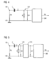
Figur 1 in einem Querschnitt; - Figur 4
- ein elektrisches Ersatzschaltbild eines ersten Ausführungsbeispiels einer Auswerteinrichtung für die Anordnung gemäß
Figur 1 ; - Figur 5
- ein zweites Ausführungsbeispiel für eine Auswerteinrichtung für die Anordnung gemäß
Figur 1 ; - Figur 6
- ein zweites Ausführungsbeispiel für eine Anordnung mit einer elektrischen Maschine und einer Messeinrichtung zur Lagerstromüberwachung, wobei eine Elektrode der Anordnung eine ringförmige Innen- und Außenkontur aufweist;
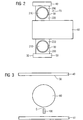
- Figur 7
- die Lagerung einer Welle der Anordnung gemäß
Figur 6 und - Figur 8
- ein drittes Ausführungsbeispiel für eine Anordnung mit einer elektrischen Maschine und einer Messeinrichtung zur Lagerstromüberwachung, wobei eine Elektrode der Anordnung eine ringförmige Innenkontur und eine beliebig anders geformte Außenkontur aufweist.
- FIG. 1
- a first embodiment of an arrangement with an electrical machine and a measuring device for bearing current monitoring in a longitudinal section;
- FIG. 2
- the storage of a shaft of the arrangement according to
FIG. 1 in a cross section; - FIG. 3
- the positioning of an electrode of the arrangement according to
FIG. 1 in a cross section; - FIG. 4
- an electrical equivalent circuit diagram of a first embodiment of an evaluation device for the arrangement according to
FIG. 1 ; - FIG. 5
- a second embodiment of an evaluation device for the arrangement according to
FIG. 1 ; - FIG. 6
- a second embodiment of an arrangement with an electrical machine and a measuring device for bearing current monitoring, wherein an electrode of the arrangement has an annular inner and outer contour;
- FIG. 7
- the storage of a shaft of the arrangement according to
FIG. 6 and - FIG. 8
- a third embodiment of an arrangement with an electric machine and a measuring device for bearing current monitoring, wherein an electrode of the arrangement has an annular inner contour and an arbitrarily differently shaped outer contour.
In den Figuren werden der Übersicht halber für identische oder vergleichbare Komponenten stets dieselben Bezugszeichen verwendet.For the sake of clarity, the same reference numbers are always used in the figures for identical or comparable components.
In der
Wie sich in der
Das Lager 70 sowie das Lager 80 können elektrisch leitend mit den beiden Gehäuseteilen 40 und 50 verbunden sein; stattdessen können beide Lager 70 und 80 auch durch einen in der Figur 1 nicht dargestellten Isolator elektrisch von dem Gehäuse 30 getrennt sein. Ob eine elektrische Isolation zwischen Lager 70 und 80 einerseits und dem Gehäuse 30 andererseits vorhanden ist oder nicht, spielt für die Funktionsweise der Messeinrichtung 20 keine Rolle.The
Wie sich in der
Die Elektrode 100 ist elektrisch an einen Messeingang 110 einer Auswerteinrichtung 120 angeschlossen. Ein anderer Messeingang 130 der Auswerteinrichtung 120 ist mit der Gehäusemasse 140 verbunden, auf deren Potential elektrisch das Gehäuse 30 der Maschine 10 liegt.The
In der
Zwischen den Wälzkörpern 210 und den beiden Lageringen 200 und 220 befindet sich der Schmiermittelfilm 90. Wie bereits ausgeführt, ist es unerheblich, ob der äußere Lagerring 200 von dem Gehäuse 30 elektrisch isoliert ist oder mit diesem elektrisch in Verbindung steht.Between the rolling
Bei stehender Maschine 10 liegen die Wälzkörper 210 in dem inneren und äußeren Lagerring auf. Die Wälzkörper können Kugeln, Zylinder, Nadeln oder andere Bauformen sein. In aller Regel, vor allem bei sehr großen Maschinen, bestehen die Wälzkörper und die Lagerschalen aus Stahl. Dadurch wird bei einer ruhenden Maschine die Welle 60 mit dem Gehäuse 30 elektrisch kurzgeschlossen. Wenn sich die Welle 60 dreht, laufen die Wälzkörper 210 auf dem Schmiermittelfilm 90; letzterer wird aus einem keilförmigen Schmiermittelvorrat vor dem jeweiligen Wälzkörper gespeist. Der Schmiermittelfilm führt zu einer elektrischen Isolation, die von der Viskosität des Schmiermittels abhängt (ändert sich mit dem Alter, der Temperatur des Lagers etc.). Je nach Maschinengröße kann sich jetzt eine Spannung zwischen Welle 60 und Gehäuse 30 aufbauen, die von den Eigenschaften des Lagers, von der Motoransteuerung (z. B. Frequenzumrichter und dessen Abschluss am Motor, etc.) und von der Qualität des Lagers selbst abhängen kann (Riefen, Rauhigkeiten etc.). Bei einer gewissen Spannung versagt die Isolation des Schmiermittelfilms 90 (bei kleinen Motoren einige 10...12 V, bei großen 70...100 V), und es tritt ein Lagerstrom auf. Die Messung des Lagerstroms wird beispielhaft weiter unten näher erläutert.When the
In der
Im Zusammenhang mit der
Kommt es nun zu einer Änderung des an der Welle 60 anliegenden elektrischen Potentials, beispielsweise weil ein elektrischer Entladungsstrom fließt, so wird sich demgemäß die elektrische Spannung Ug zwischen der Welle 60 und der Gehäusemasse 140 ändern. Aufgrund dieser Spannungsänderung wird es einen elektrischen Verschiebestrom i geben, der durch den Widerstand R fließt und der zu einem Spannungsabfall an diesem Widerstand R führt. Für den Strom i gilt näherungsweise: ![]()
![]()
Der Spannungsabfall an dem Widerstand R wird als Messspannung Um weiterverwendet und in den Komparator 300 eingespeist. Der Komparator 300 vergleicht die Messspannung Um mit einer vorgegebenen Mindestspannung und erzeugt ein einen Lagerstromfluss anzeigendes Messsignal Ms, wenn die Messspannung Um die vorgegebene Mindestspannung überschreitet.The voltage drop across the resistor R is further used as the measurement voltage Um and fed to the
Die Werte für R und C werden vorzugsweise jeweils an die Art der Maschine (Motor / Generator, Baugröße, Konstruktion, Leistung) angepasst; hierzu werden beispielsweise mit unterschiedlichen Werten für R und C Testmessungen durchgeführt, bis ein R/C-Wertepaar mit für die jeweilige Maschine optimalen Messeigenschaften bestimmt worden ist.The values for R and C are preferably adapted respectively to the type of machine (motor / generator, size, construction, power); For this purpose, test measurements are carried out, for example, with different values for R and C until an R / C value pair has been determined with optimal measuring properties for the respective machine.
Beispielsweise erzeugt der Komparator 300 ein binäres Messsignal, z. B. mit einer logischen 1, wenn die vorgegebene Mindestspannung überschritten wird. Stellt der Komparator 300 hingegen fest, dass die Spannung Um die vorgegebene Mindestspannung nicht erreicht, so erzeugt er ausgangsseitig als Messsignal Ms beispielsweise ein binäres Ausgangssignal mit einer logischen 0.For example, the
Die Auswerteinrichtung 120 macht sich zunutze, dass ein Entladungsstrom von der Welle 60 über die Lager 70 oder 80 zu dem Gehäuse 30 stets zu einer relativ großen Spannungsänderung dUg/dt führt und dass demgemäß im Falle eines Lagerstromflusses eine entsprechend große Spannung Um auftreten wird, die von dem Komparator 300 feststellbar ist. Andere Stromflüsse hingegen, die nicht auf einer Entladung eines an der Welle 60 anliegenden Potentials beruhen, werden in der Regel geringere zeitliche Änderungen aufweisen, so dass diese von der Auswerteinrichtung 120 nicht erfasst werden, da nämlich der Quotient dUg/dt bei diesen anderen Stromflüssen zu gering sein wird.The
In der
Die Funktion des Bandpasses 310 besteht darin, Störfrequenzen, die nicht auf einen Entladevorgang an der Welle 60 zurückgehen, aus der Messspannung Um herauszufiltern und eine gefilterte Messspannung Um' zu bilden, damit Störfrequenzen die Arbeitsweise des Komparators 300 nicht beeinträchtigen. Vorzugsweise wird der Bandpass in einem Frequenzbereich zwischen 1 MHz und 100 MHz eine nur geringe Dämpfung aufweisen, da in diesem Frequenzbereich die von der Auswerteinrichtung 120 zu erfassenden Frequenzen des Entladestroms liegen werden. Außerhalb des genannten Frequenzbereichs zwischen 1 MHz und 100 MHz wird das Signal Um unterdrückt.The function of the
In der
Ein wesentlicher Vorteil der ringförmigen Ausgestaltung der Elektrode 100 ist darin zu sehen, dass im Falle einer Unwucht der Welle 60 ein deutlich geringerer Fehlerstrom auftreten wird als bei dem Ausführungsbeispiel gemäß
Ist die Welle 60 bei dem Ausführungsbeispiel gemäß ![]()
![]()
![]()
![]()
Der Fehlerstrom If wird bei dem Ausführungsbeispiel gemäß Figur 6 nicht merklich stören, da nämlich im Falle einer Unwucht während der Rotation der Welle zwar manche Ringabschnitte zeitweise einen kleineren Abstand zur Welle aufweisen werden als sonst, jedoch die gegenüberliegenden Ringabschnitte im Gegentakt einen größeren Abstand zu der Welle 60 aufweisen werden. Es kommt also mit anderen Worten zu einer Kompensation und einer weitgehenden Eliminierung des Fehlerstroms, da diejenigen Ringabschnitte, die aufgrund eines geringeren Abstands zwischen Welle 60 und Ringelektrode 100 zeitweise zu einer großen Kapazität führen würden, von anderen Ringabschnitten kompensiert werden, deren Kapazitätsanteil aufgrund des größeren Abstands zwischen Welle 60 und Ringelektrode 100 gerade kleiner wird.In the case of an imbalance during the rotation of the shaft, the fault current If will in the event of an imbalance during the rotation of the shaft at times have a smaller distance to the shaft than usual, but the opposite ring portions in push-pull a greater distance from the
Zusammengefasst wird sich bei dem Ausführungsbeispiel gemäß
In der
Im Unterschied zu dem Ausführungsbeispiel gemäß
Aufgrund der ringförmigen Innenkontur und aufgrund der Ringform des Spalts S ergibt sich wiederum die bereits im Zusammenhang mit den ![]()
![]()
Claims (12)
- Method for monitoring the bearing current in an electrical machine (10) in particular an electric motor or an electrical generator, which has a shaft (60) which is mounted by means of at least one bearing (70, 80) in a housing (30) such that it can rotate, characterized in that- a measurement capacitance (C) is formed by an electrode (100), which is arranged at a distance (d) from the shaft, and by the shaft - on the basis of the gap (S) between the electrode and the shaft - and an electrical displacement current (i) is measured which flows through this measurement capacitance when the voltage (Ug) which is present between the shaft and the housing rate of change (dUg/dt), and- a measurement signal (Ms) which indicates a bearing current flow is produced when the displacement current or a measurement variable formed by this displacement current complies with a predetermined initiation criterion.
- Method according to Claim 1, characterized in that the measurement capacitance is formed by an electrode which has a circular internal contour (400), through which the shaft is passed and which is arranged concentrically with respect to the shaft such that the gap is annular.
- Method according to one of the preceding claims, characterized in that the initiation criterion is considered to be satisfied when the displacement current or a measurement variable formed by this displacement current reaches or exceeds a predetermined limit current.
- Method according to one of the preceding claims, characterized in that- the displacement current is passed through a resistance (R), and- the initiation criterion is considered to be satisfied when the measurement voltage dropped across the resistance, or a variable derived from it, satisfies a predetermined voltage initiation criterion.
- Method according to Claim 4, characterized in that the voltage initiation criterion is considered to be satisfied when the measurement voltage dropped across the resistance, or a variable derived from it, reaches or exceeds a predetermined limit voltage.
- Method according to one of the preceding claims, characterized in that the measurement voltage dropped across the resistance is subjected to high-pass and/or bandpass filtering, and the measurement signal is produced when the filtered measurement voltage, or a variable derived from it, satisfies the predetermined voltage initiation criterion.
- Arrangement having an electric machine (10), in particular an electric motor or a generator, which has a shaft (60) which is mounted by means of at least one bearing (70, 80) in a housing (30) such that it can rotate, and having a measurement device (20) for monitoring the bearing current, characterized in that- the measurement device has an electrode (100) which is arranged at a distance (d) from the shaft and, together with the shaft, forms a measurement capacitance (C) on the basis of the gap (S) between the shaft and the electrode, and- the measurement device has an evaluation device (120) which- is connected to the electrode and detects an electric displacement current (i) which flows through this measurement capacitance (c) when the voltage (Ug) which is present between the shaft and the housing rate of change, and- produces a measurement signal, which indicates a bearing current flow, when the displacement current or a measurement variable formed by this displacement current complies with a predetermined initiation criterion.
- Arrangement according to Claim 7, characterized in that the electrode (100) has a circular internal contour, which is arranged concentrically with respect to the shaft, such that the gap is annular.
- Arrangement according to one of the preceding Claims 7-8, characterized in that the evaluation device is designed such that it considers the initiation criterion to be satisfied when the displacement current or a measurement variable formed by this displacement current reaches or exceeds a predetermined limit current.
- Arrangement according to one of the preceding Claims 7-9, characterized in that- the evaluation device has an electrical resistance which is connected to the electrode, and- the evaluation device is designed such that it considers the initiation criterion to be satisfied when the measurement voltage dropped across the resistance or a variable derived from it satisfies a predetermined voltage initiation criterion.
- Arrangement according to Claim 10, characterized in that the evaluation device is designed such that it considers the initiation criterion to be satisfied when the measurement Voltage dropped across the resistance or a variable derived from it reaches or exceeds a predetermined limit voltage.
- Arrangement according to one of the preceding Claims 7-11, characterized in that- the evaluation device has a high-pass filter and/or a bandpass filter (310), which is connected to the electrical resistance, and- the evaluation device is designed such that it considers the initiation criterion to be satisfied when the filtered measurement voltage or a variable derived from it satisfies the predetermined voltage initiation criterion.
Applications Claiming Priority (2)
| Application Number | Priority Date | Filing Date | Title |
|---|---|---|---|
| DE102008035613A DE102008035613A1 (en) | 2008-07-25 | 2008-07-25 | Method and arrangement for bearing current monitoring of an electrical machine |
| PCT/EP2009/059341 WO2010010081A1 (en) | 2008-07-25 | 2009-07-21 | Method and system for monitoring the bearing current of an electrical machine |
Publications (2)
| Publication Number | Publication Date |
|---|---|
| EP2304866A1 EP2304866A1 (en) | 2011-04-06 |
| EP2304866B1 true EP2304866B1 (en) | 2012-04-04 |
Family
ID=41396267
Family Applications (1)
| Application Number | Title | Priority Date | Filing Date |
|---|---|---|---|
| EP09780863A Not-in-force EP2304866B1 (en) | 2008-07-25 | 2009-07-21 | Method and system for monitoring the bearing current of an electrical machine |
Country Status (6)
| Country | Link |
|---|---|
| US (1) | US8610591B2 (en) |
| EP (1) | EP2304866B1 (en) |
| CN (1) | CN102106064B (en) |
| AT (1) | ATE552643T1 (en) |
| DE (1) | DE102008035613A1 (en) |
| WO (1) | WO2010010081A1 (en) |
Families Citing this family (12)
| Publication number | Priority date | Publication date | Assignee | Title |
|---|---|---|---|---|
| DE102010002297A1 (en) | 2010-02-24 | 2011-08-25 | Siemens Aktiengesellschaft, 80333 | Method and device for evaluating the damage to rolling bearings, in particular to converter-fed electrical machines |
| WO2011107108A1 (en) * | 2010-03-01 | 2011-09-09 | Siemens Aktiengesellschaft | Bearing current sensor device having an energy converter |
| RU2550155C2 (en) * | 2010-05-11 | 2015-05-10 | Сименс Акциенгезелльшафт | Device and method for current measurement in bearing |
| US10138872B2 (en) * | 2016-09-20 | 2018-11-27 | General Electric Company | System and method for detecting ground brush lifting |
| DE102017109049A1 (en) * | 2017-04-27 | 2018-10-31 | Schaeffler Technologies AG & Co. KG | Device and method for compensation of shaft voltage and bearing currents by capacitive negative feedback |
| EP3704464B1 (en) * | 2017-11-03 | 2021-03-31 | ABB Schweiz AG | Arrangement for monitoring antifriction bearing of rotating shaft of rotating electric machine |
| RU2713467C1 (en) * | 2018-10-18 | 2020-02-05 | Федеральное государственное бюджетное образовательное учреждение высшего образования "Оренбургский государственный университет" | Method of monitoring electric current through bearings of electric machine and current transformer for its implementation |
| EP3832858A1 (en) | 2019-12-02 | 2021-06-09 | Siemens Aktiengesellschaft | Arrangement comprising an electric rotating machine |
| DE102020215977A1 (en) | 2020-12-16 | 2022-06-23 | Robert Bosch Gesellschaft mit beschränkter Haftung | roller bearing |
| DE102020215980A1 (en) | 2020-12-16 | 2022-06-23 | Robert Bosch Gesellschaft mit beschränkter Haftung | roller bearing |
| DE102021106512A1 (en) | 2021-03-17 | 2022-09-22 | Tdk Electronics Ag | Measuring device, electric motor and method for measuring a shaft voltage of an electric motor |
| US11569712B2 (en) | 2021-04-05 | 2023-01-31 | General Electric Renovables Espana, S.L. | System and method for detecting bearing insulation and ground brush health in a generator |
Family Cites Families (16)
| Publication number | Priority date | Publication date | Assignee | Title |
|---|---|---|---|---|
| CH399963A (en) | 1962-05-22 | 1965-09-30 | Bbc Brown Boveri & Cie | Device for monitoring bearings |
| US3904940A (en) * | 1974-10-10 | 1975-09-09 | Allis Chalmers | Means for detecting ground insulation failure for rotary electric machines |
| US4097794A (en) * | 1976-11-15 | 1978-06-27 | Allis-Chalmers Corporation | Static means for detecting ground insulation failure for rotary electric machines |
| US4147982A (en) | 1977-10-06 | 1979-04-03 | Electric Power Research Institute, Inc. | Turbine generator ground current arcing detection apparatus and method |
| US4237454A (en) * | 1979-01-29 | 1980-12-02 | General Electric Company | System for monitoring bearings and other rotating equipment |
| NL8103161A (en) * | 1981-06-30 | 1983-01-17 | Skf Ind Trading & Dev | MEASUREMENT SYSTEM FOR MEASURING THE VARIATION OF THE CAPACITIVE IMPEDANCE OF A BEARING-MOUNTED BEARING. |
| DE3235194A1 (en) * | 1982-09-23 | 1984-03-29 | Robert Bosch Gmbh, 7000 Stuttgart | METHOD AND DEVICE FOR SECURING TOOLS |
| AT398844B (en) | 1988-04-18 | 1995-02-27 | Franek Friedrich Dipl Ing Dr | DEVICE FOR MEASURING A DISTANCE BETWEEN RELATIVELY MOVING ELEMENTS |
| US6460013B1 (en) * | 1999-05-06 | 2002-10-01 | Paul I. Nippes | Shaft voltage current monitoring system for early warning and problem detection |
| US6967586B2 (en) * | 2000-10-20 | 2005-11-22 | Sankyo Seiki Mfg. Co., Ltd. | Bearing test method, bearing test device, bearing monitoring device and storage device |
| US6727725B2 (en) * | 2001-05-01 | 2004-04-27 | Square D Company | Motor bearing damage detection via wavelet analysis of the starting current transient |
| US20040263342A1 (en) * | 2003-06-30 | 2004-12-30 | Matlock Milton Gregory | System for monitoring motors |
| DE102005027670A1 (en) * | 2005-06-15 | 2007-01-11 | Siemens Ag | Arrangement and method for bearing current monitoring of an electric motor |
| ATE439695T1 (en) * | 2006-03-13 | 2009-08-15 | Skf Ab | METHOD AND DEVICE FOR DETECTING ELECTRICAL DISCHARGES IN A BEARING OF AN ELECTRICAL DRIVE SYSTEM |
| US20080079435A1 (en) * | 2006-09-08 | 2008-04-03 | Trek, Inc. | Electrostatic Voltmeter With Spacing-Independent Speed of Response |
| EP2455772B1 (en) * | 2007-06-04 | 2014-12-31 | Eaton Corporation | System and method for bearing fault detection using stator current noise cancellation |
-
2008
- 2008-07-25 DE DE102008035613A patent/DE102008035613A1/en not_active Withdrawn
-
2009
- 2009-07-21 EP EP09780863A patent/EP2304866B1/en not_active Not-in-force
- 2009-07-21 CN CN2009801285250A patent/CN102106064B/en not_active Expired - Fee Related
- 2009-07-21 US US13/055,818 patent/US8610591B2/en not_active Expired - Fee Related
- 2009-07-21 WO PCT/EP2009/059341 patent/WO2010010081A1/en active Application Filing
- 2009-07-21 AT AT09780863T patent/ATE552643T1/en active
Also Published As
| Publication number | Publication date |
|---|---|
| CN102106064B (en) | 2013-08-07 |
| DE102008035613A1 (en) | 2010-01-28 |
| ATE552643T1 (en) | 2012-04-15 |
| US8610591B2 (en) | 2013-12-17 |
| US20110175631A1 (en) | 2011-07-21 |
| EP2304866A1 (en) | 2011-04-06 |
| CN102106064A (en) | 2011-06-22 |
| WO2010010081A1 (en) | 2010-01-28 |
Similar Documents
| Publication | Publication Date | Title |
|---|---|---|
| EP2304866B1 (en) | Method and system for monitoring the bearing current of an electrical machine | |
| EP1537390B1 (en) | Method for detecting oscillations of the shafting of an electric machine | |
| EP1537428B1 (en) | Method and device for detecting sparking and spark erosion in electric machines | |
| DE102014007690A1 (en) | Slip ring unit and method for condition monitoring of a slip ring unit | |
| EP2516313A2 (en) | Monitoring a supporting and propulsion means of an elevator system | |
| DE102005027670A1 (en) | Arrangement and method for bearing current monitoring of an electric motor | |
| DE1183316B (en) | Device for monitoring bearings | |
| WO2008006655A1 (en) | Method and device for detecting interlaminar short circuits | |
| EP2476916B1 (en) | Piston-cylinder unit with device for position tracking | |
| EP2264472B1 (en) | Device for measuring the loss factor | |
| DE102004013606B4 (en) | Device for measuring disturbances or interruptions in the inner smoothing layer in medium and high voltage cables | |
| WO2018196925A1 (en) | Capacitive bypass for reducing electrical shaft voltages or bearing voltages | |
| EP2876308A1 (en) | Cylinder-piston unit with evaluation unit for determining the position of the piston | |
| EP2092279A1 (en) | Device for determining and/or monitoring a process quantity | |
| DE102019117879A1 (en) | Method and sensor for monitoring a state of an ensemble of at least one first component in a second component | |
| WO2018095675A1 (en) | Measuring device for measuring the wear of carbon brushes | |
| DE102014112116A1 (en) | Device for monitoring the position of a tool or tool carrier on a work spindle | |
| EP3707807A1 (en) | Method for monitoring rolling bearings | |
| EP2125280B1 (en) | Device for machining workpieces | |
| DE202017106703U1 (en) | Device for monitoring rolling bearings | |
| WO2019179645A1 (en) | Method and measuring assembly for detecting an electromagnetic disturbance influence on a line core of an electrical line | |
| WO2018206707A1 (en) | Measuring arrangement for measuring a position and/or a rotational speed of a shaft | |
| EP4204699B1 (en) | Bearing element with a sensor and a telemetric device | |
| CH711878B1 (en) | Method and device for determining the specific length resistance of a multi-wire cable. | |
| DE102019205377B4 (en) | Electrical machine and method for determining a fault in an electrical machine |
Legal Events
| Date | Code | Title | Description |
|---|---|---|---|
| PUAI | Public reference made under article 153(3) epc to a published international application that has entered the european phase |
Free format text: ORIGINAL CODE: 0009012 |
|
| 17P | Request for examination filed |
Effective date: 20110105 |
|
| AK | Designated contracting states |
Kind code of ref document: A1 Designated state(s): AT BE BG CH CY CZ DE DK EE ES FI FR GB GR HR HU IE IS IT LI LT LU LV MC MK MT NL NO PL PT RO SE SI SK SM TR |
|
| AX | Request for extension of the european patent |
Extension state: AL BA RS |
|
| GRAP | Despatch of communication of intention to grant a patent |
Free format text: ORIGINAL CODE: EPIDOSNIGR1 |
|
| DAX | Request for extension of the european patent (deleted) | ||
| GRAS | Grant fee paid |
Free format text: ORIGINAL CODE: EPIDOSNIGR3 |
|
| GRAA | (expected) grant |
Free format text: ORIGINAL CODE: 0009210 |
|
| AK | Designated contracting states |
Kind code of ref document: B1 Designated state(s): AT BE BG CH CY CZ DE DK EE ES FI FR GB GR HR HU IE IS IT LI LT LU LV MC MK MT NL NO PL PT RO SE SI SK SM TR |
|
| REG | Reference to a national code |
Ref country code: GB Ref legal event code: FG4D Free format text: NOT ENGLISH |
|
| REG | Reference to a national code |
Ref country code: CH Ref legal event code: EP |
|
| REG | Reference to a national code |
Ref country code: AT Ref legal event code: REF Ref document number: 552643 Country of ref document: AT Kind code of ref document: T Effective date: 20120415 |
|
| REG | Reference to a national code |
Ref country code: IE Ref legal event code: FG4D Free format text: LANGUAGE OF EP DOCUMENT: GERMAN |
|
| REG | Reference to a national code |
Ref country code: DE Ref legal event code: R096 Ref document number: 502009003216 Country of ref document: DE Effective date: 20120606 |
|
| REG | Reference to a national code |
Ref country code: NL Ref legal event code: VDEP Effective date: 20120404 |
|
| LTIE | Lt: invalidation of european patent or patent extension |
Effective date: 20120404 |
|
| PG25 | Lapsed in a contracting state [announced via postgrant information from national office to epo] |
Ref country code: SE Free format text: LAPSE BECAUSE OF FAILURE TO SUBMIT A TRANSLATION OF THE DESCRIPTION OR TO PAY THE FEE WITHIN THE PRESCRIBED TIME-LIMIT Effective date: 20120404 Ref country code: LT Free format text: LAPSE BECAUSE OF FAILURE TO SUBMIT A TRANSLATION OF THE DESCRIPTION OR TO PAY THE FEE WITHIN THE PRESCRIBED TIME-LIMIT Effective date: 20120404 Ref country code: IS Free format text: LAPSE BECAUSE OF FAILURE TO SUBMIT A TRANSLATION OF THE DESCRIPTION OR TO PAY THE FEE WITHIN THE PRESCRIBED TIME-LIMIT Effective date: 20120804 Ref country code: CY Free format text: LAPSE BECAUSE OF FAILURE TO SUBMIT A TRANSLATION OF THE DESCRIPTION OR TO PAY THE FEE WITHIN THE PRESCRIBED TIME-LIMIT Effective date: 20120404 Ref country code: NO Free format text: LAPSE BECAUSE OF FAILURE TO SUBMIT A TRANSLATION OF THE DESCRIPTION OR TO PAY THE FEE WITHIN THE PRESCRIBED TIME-LIMIT Effective date: 20120704 Ref country code: FI Free format text: LAPSE BECAUSE OF FAILURE TO SUBMIT A TRANSLATION OF THE DESCRIPTION OR TO PAY THE FEE WITHIN THE PRESCRIBED TIME-LIMIT Effective date: 20120404 Ref country code: PL Free format text: LAPSE BECAUSE OF FAILURE TO SUBMIT A TRANSLATION OF THE DESCRIPTION OR TO PAY THE FEE WITHIN THE PRESCRIBED TIME-LIMIT Effective date: 20120404 Ref country code: SI Free format text: LAPSE BECAUSE OF FAILURE TO SUBMIT A TRANSLATION OF THE DESCRIPTION OR TO PAY THE FEE WITHIN THE PRESCRIBED TIME-LIMIT Effective date: 20120404 |
|
| PG25 | Lapsed in a contracting state [announced via postgrant information from national office to epo] |
Ref country code: HR Free format text: LAPSE BECAUSE OF FAILURE TO SUBMIT A TRANSLATION OF THE DESCRIPTION OR TO PAY THE FEE WITHIN THE PRESCRIBED TIME-LIMIT Effective date: 20120404 Ref country code: PT Free format text: LAPSE BECAUSE OF FAILURE TO SUBMIT A TRANSLATION OF THE DESCRIPTION OR TO PAY THE FEE WITHIN THE PRESCRIBED TIME-LIMIT Effective date: 20120806 Ref country code: LV Free format text: LAPSE BECAUSE OF FAILURE TO SUBMIT A TRANSLATION OF THE DESCRIPTION OR TO PAY THE FEE WITHIN THE PRESCRIBED TIME-LIMIT Effective date: 20120404 Ref country code: GR Free format text: LAPSE BECAUSE OF FAILURE TO SUBMIT A TRANSLATION OF THE DESCRIPTION OR TO PAY THE FEE WITHIN THE PRESCRIBED TIME-LIMIT Effective date: 20120705 |
|
| BERE | Be: lapsed |
Owner name: SIEMENS A.G. Effective date: 20120731 |
|
| PG25 | Lapsed in a contracting state [announced via postgrant information from national office to epo] |
Ref country code: DK Free format text: LAPSE BECAUSE OF FAILURE TO SUBMIT A TRANSLATION OF THE DESCRIPTION OR TO PAY THE FEE WITHIN THE PRESCRIBED TIME-LIMIT Effective date: 20120404 Ref country code: CZ Free format text: LAPSE BECAUSE OF FAILURE TO SUBMIT A TRANSLATION OF THE DESCRIPTION OR TO PAY THE FEE WITHIN THE PRESCRIBED TIME-LIMIT Effective date: 20120404 Ref country code: EE Free format text: LAPSE BECAUSE OF FAILURE TO SUBMIT A TRANSLATION OF THE DESCRIPTION OR TO PAY THE FEE WITHIN THE PRESCRIBED TIME-LIMIT Effective date: 20120404 Ref country code: NL Free format text: LAPSE BECAUSE OF FAILURE TO SUBMIT A TRANSLATION OF THE DESCRIPTION OR TO PAY THE FEE WITHIN THE PRESCRIBED TIME-LIMIT Effective date: 20120404 Ref country code: RO Free format text: LAPSE BECAUSE OF FAILURE TO SUBMIT A TRANSLATION OF THE DESCRIPTION OR TO PAY THE FEE WITHIN THE PRESCRIBED TIME-LIMIT Effective date: 20120404 Ref country code: SK Free format text: LAPSE BECAUSE OF FAILURE TO SUBMIT A TRANSLATION OF THE DESCRIPTION OR TO PAY THE FEE WITHIN THE PRESCRIBED TIME-LIMIT Effective date: 20120404 |
|
| PLBE | No opposition filed within time limit |
Free format text: ORIGINAL CODE: 0009261 |
|
| STAA | Information on the status of an ep patent application or granted ep patent |
Free format text: STATUS: NO OPPOSITION FILED WITHIN TIME LIMIT |
|
| PG25 | Lapsed in a contracting state [announced via postgrant information from national office to epo] |
Ref country code: MK Free format text: LAPSE BECAUSE OF FAILURE TO SUBMIT A TRANSLATION OF THE DESCRIPTION OR TO PAY THE FEE WITHIN THE PRESCRIBED TIME-LIMIT Effective date: 20120404 Ref country code: IT Free format text: LAPSE BECAUSE OF FAILURE TO SUBMIT A TRANSLATION OF THE DESCRIPTION OR TO PAY THE FEE WITHIN THE PRESCRIBED TIME-LIMIT Effective date: 20120404 Ref country code: MC Free format text: LAPSE BECAUSE OF NON-PAYMENT OF DUE FEES Effective date: 20120731 |
|
| 26N | No opposition filed |
Effective date: 20130107 |
|
| PG25 | Lapsed in a contracting state [announced via postgrant information from national office to epo] |
Ref country code: ES Free format text: LAPSE BECAUSE OF FAILURE TO SUBMIT A TRANSLATION OF THE DESCRIPTION OR TO PAY THE FEE WITHIN THE PRESCRIBED TIME-LIMIT Effective date: 20120715 |
|
| REG | Reference to a national code |
Ref country code: DE Ref legal event code: R097 Ref document number: 502009003216 Country of ref document: DE Effective date: 20130107 |
|
| REG | Reference to a national code |
Ref country code: IE Ref legal event code: MM4A |
|
| PG25 | Lapsed in a contracting state [announced via postgrant information from national office to epo] |
Ref country code: BE Free format text: LAPSE BECAUSE OF NON-PAYMENT OF DUE FEES Effective date: 20120731 |
|
| PG25 | Lapsed in a contracting state [announced via postgrant information from national office to epo] |
Ref country code: MT Free format text: LAPSE BECAUSE OF FAILURE TO SUBMIT A TRANSLATION OF THE DESCRIPTION OR TO PAY THE FEE WITHIN THE PRESCRIBED TIME-LIMIT Effective date: 20120404 Ref country code: IE Free format text: LAPSE BECAUSE OF NON-PAYMENT OF DUE FEES Effective date: 20120721 Ref country code: BG Free format text: LAPSE BECAUSE OF FAILURE TO SUBMIT A TRANSLATION OF THE DESCRIPTION OR TO PAY THE FEE WITHIN THE PRESCRIBED TIME-LIMIT Effective date: 20120704 |
|
| REG | Reference to a national code |
Ref country code: CH Ref legal event code: PL |
|
| PG25 | Lapsed in a contracting state [announced via postgrant information from national office to epo] |
Ref country code: CH Free format text: LAPSE BECAUSE OF NON-PAYMENT OF DUE FEES Effective date: 20130731 Ref country code: LI Free format text: LAPSE BECAUSE OF NON-PAYMENT OF DUE FEES Effective date: 20130731 Ref country code: TR Free format text: LAPSE BECAUSE OF FAILURE TO SUBMIT A TRANSLATION OF THE DESCRIPTION OR TO PAY THE FEE WITHIN THE PRESCRIBED TIME-LIMIT Effective date: 20120404 |
|
| PG25 | Lapsed in a contracting state [announced via postgrant information from national office to epo] |
Ref country code: SM Free format text: LAPSE BECAUSE OF FAILURE TO SUBMIT A TRANSLATION OF THE DESCRIPTION OR TO PAY THE FEE WITHIN THE PRESCRIBED TIME-LIMIT Effective date: 20120404 Ref country code: LU Free format text: LAPSE BECAUSE OF NON-PAYMENT OF DUE FEES Effective date: 20120721 |
|
| PG25 | Lapsed in a contracting state [announced via postgrant information from national office to epo] |
Ref country code: HU Free format text: LAPSE BECAUSE OF FAILURE TO SUBMIT A TRANSLATION OF THE DESCRIPTION OR TO PAY THE FEE WITHIN THE PRESCRIBED TIME-LIMIT Effective date: 20090721 |
|
| REG | Reference to a national code |
Ref country code: AT Ref legal event code: MM01 Ref document number: 552643 Country of ref document: AT Kind code of ref document: T Effective date: 20140721 |
|
| PG25 | Lapsed in a contracting state [announced via postgrant information from national office to epo] |
Ref country code: AT Free format text: LAPSE BECAUSE OF NON-PAYMENT OF DUE FEES Effective date: 20140721 |
|
| REG | Reference to a national code |
Ref country code: FR Ref legal event code: PLFP Year of fee payment: 8 |
|
| REG | Reference to a national code |
Ref country code: FR Ref legal event code: PLFP Year of fee payment: 9 |
|
| REG | Reference to a national code |
Ref country code: FR Ref legal event code: PLFP Year of fee payment: 10 |
|
| PGFP | Annual fee paid to national office [announced via postgrant information from national office to epo] |
Ref country code: DE Payment date: 20180920 Year of fee payment: 10 Ref country code: FR Payment date: 20180726 Year of fee payment: 10 |
|
| PGFP | Annual fee paid to national office [announced via postgrant information from national office to epo] |
Ref country code: GB Payment date: 20180711 Year of fee payment: 10 |
|
| REG | Reference to a national code |
Ref country code: DE Ref legal event code: R119 Ref document number: 502009003216 Country of ref document: DE |
|
| GBPC | Gb: european patent ceased through non-payment of renewal fee |
Effective date: 20190721 |
|
| PG25 | Lapsed in a contracting state [announced via postgrant information from national office to epo] |
Ref country code: DE Free format text: LAPSE BECAUSE OF NON-PAYMENT OF DUE FEES Effective date: 20200201 Ref country code: GB Free format text: LAPSE BECAUSE OF NON-PAYMENT OF DUE FEES Effective date: 20190721 |
|
| PG25 | Lapsed in a contracting state [announced via postgrant information from national office to epo] |
Ref country code: FR Free format text: LAPSE BECAUSE OF NON-PAYMENT OF DUE FEES Effective date: 20190731 |