EP2304232B1 - Verfahren zur auslegung einer windkraftanlage - Google Patents
Verfahren zur auslegung einer windkraftanlage Download PDFInfo
- Publication number
- EP2304232B1 EP2304232B1 EP09713132.0A EP09713132A EP2304232B1 EP 2304232 B1 EP2304232 B1 EP 2304232B1 EP 09713132 A EP09713132 A EP 09713132A EP 2304232 B1 EP2304232 B1 EP 2304232B1
- Authority
- EP
- European Patent Office
- Prior art keywords
- rotor
- bearing
- wind
- rotor blade
- wind power
- Prior art date
- Legal status (The legal status is an assumption and is not a legal conclusion. Google has not performed a legal analysis and makes no representation as to the accuracy of the status listed.)
- Not-in-force
Links
Images


Classifications
-
- F—MECHANICAL ENGINEERING; LIGHTING; HEATING; WEAPONS; BLASTING
- F03—MACHINES OR ENGINES FOR LIQUIDS; WIND, SPRING, OR WEIGHT MOTORS; PRODUCING MECHANICAL POWER OR A REACTIVE PROPULSIVE THRUST, NOT OTHERWISE PROVIDED FOR
- F03D—WIND MOTORS
- F03D7/00—Controlling wind motors
- F03D7/02—Controlling wind motors the wind motors having rotation axis substantially parallel to the air flow entering the rotor
- F03D7/022—Adjusting aerodynamic properties of the blades
- F03D7/0224—Adjusting blade pitch
-
- F—MECHANICAL ENGINEERING; LIGHTING; HEATING; WEAPONS; BLASTING
- F03—MACHINES OR ENGINES FOR LIQUIDS; WIND, SPRING, OR WEIGHT MOTORS; PRODUCING MECHANICAL POWER OR A REACTIVE PROPULSIVE THRUST, NOT OTHERWISE PROVIDED FOR
- F03D—WIND MOTORS
- F03D7/00—Controlling wind motors
- F03D7/02—Controlling wind motors the wind motors having rotation axis substantially parallel to the air flow entering the rotor
- F03D7/0296—Controlling wind motors the wind motors having rotation axis substantially parallel to the air flow entering the rotor to prevent, counteract or reduce noise emissions
-
- F—MECHANICAL ENGINEERING; LIGHTING; HEATING; WEAPONS; BLASTING
- F03—MACHINES OR ENGINES FOR LIQUIDS; WIND, SPRING, OR WEIGHT MOTORS; PRODUCING MECHANICAL POWER OR A REACTIVE PROPULSIVE THRUST, NOT OTHERWISE PROVIDED FOR
- F03D—WIND MOTORS
- F03D80/00—Details, components or accessories not provided for in groups F03D1/00 - F03D17/00
- F03D80/70—Bearing or lubricating arrangements
-
- F—MECHANICAL ENGINEERING; LIGHTING; HEATING; WEAPONS; BLASTING
- F16—ENGINEERING ELEMENTS AND UNITS; GENERAL MEASURES FOR PRODUCING AND MAINTAINING EFFECTIVE FUNCTIONING OF MACHINES OR INSTALLATIONS; THERMAL INSULATION IN GENERAL
- F16C—SHAFTS; FLEXIBLE SHAFTS; ELEMENTS OR CRANKSHAFT MECHANISMS; ROTARY BODIES OTHER THAN GEARING ELEMENTS; BEARINGS
- F16C19/00—Bearings with rolling contact, for exclusively rotary movement
- F16C19/22—Bearings with rolling contact, for exclusively rotary movement with bearing rollers essentially of the same size in one or more circular rows, e.g. needle bearings
- F16C19/34—Bearings with rolling contact, for exclusively rotary movement with bearing rollers essentially of the same size in one or more circular rows, e.g. needle bearings for both radial and axial load
- F16C19/38—Bearings with rolling contact, for exclusively rotary movement with bearing rollers essentially of the same size in one or more circular rows, e.g. needle bearings for both radial and axial load with two or more rows of rollers
- F16C19/381—Bearings with rolling contact, for exclusively rotary movement with bearing rollers essentially of the same size in one or more circular rows, e.g. needle bearings for both radial and axial load with two or more rows of rollers with at least one row for radial load in combination with at least one row for axial load
-
- F—MECHANICAL ENGINEERING; LIGHTING; HEATING; WEAPONS; BLASTING
- F05—INDEXING SCHEMES RELATING TO ENGINES OR PUMPS IN VARIOUS SUBCLASSES OF CLASSES F01-F04
- F05B—INDEXING SCHEME RELATING TO WIND, SPRING, WEIGHT, INERTIA OR LIKE MOTORS, TO MACHINES OR ENGINES FOR LIQUIDS COVERED BY SUBCLASSES F03B, F03D AND F03G
- F05B2260/00—Function
- F05B2260/96—Preventing, counteracting or reducing vibration or noise
-
- F—MECHANICAL ENGINEERING; LIGHTING; HEATING; WEAPONS; BLASTING
- F05—INDEXING SCHEMES RELATING TO ENGINES OR PUMPS IN VARIOUS SUBCLASSES OF CLASSES F01-F04
- F05B—INDEXING SCHEME RELATING TO WIND, SPRING, WEIGHT, INERTIA OR LIKE MOTORS, TO MACHINES OR ENGINES FOR LIQUIDS COVERED BY SUBCLASSES F03B, F03D AND F03G
- F05B2270/00—Control
- F05B2270/30—Control parameters, e.g. input parameters
- F05B2270/32—Wind speeds
-
- F—MECHANICAL ENGINEERING; LIGHTING; HEATING; WEAPONS; BLASTING
- F05—INDEXING SCHEMES RELATING TO ENGINES OR PUMPS IN VARIOUS SUBCLASSES OF CLASSES F01-F04
- F05B—INDEXING SCHEME RELATING TO WIND, SPRING, WEIGHT, INERTIA OR LIKE MOTORS, TO MACHINES OR ENGINES FOR LIQUIDS COVERED BY SUBCLASSES F03B, F03D AND F03G
- F05B2270/00—Control
- F05B2270/30—Control parameters, e.g. input parameters
- F05B2270/321—Wind directions
-
- F—MECHANICAL ENGINEERING; LIGHTING; HEATING; WEAPONS; BLASTING
- F05—INDEXING SCHEMES RELATING TO ENGINES OR PUMPS IN VARIOUS SUBCLASSES OF CLASSES F01-F04
- F05B—INDEXING SCHEME RELATING TO WIND, SPRING, WEIGHT, INERTIA OR LIKE MOTORS, TO MACHINES OR ENGINES FOR LIQUIDS COVERED BY SUBCLASSES F03B, F03D AND F03G
- F05B2270/00—Control
- F05B2270/30—Control parameters, e.g. input parameters
- F05B2270/334—Vibration measurements
-
- F—MECHANICAL ENGINEERING; LIGHTING; HEATING; WEAPONS; BLASTING
- F16—ENGINEERING ELEMENTS AND UNITS; GENERAL MEASURES FOR PRODUCING AND MAINTAINING EFFECTIVE FUNCTIONING OF MACHINES OR INSTALLATIONS; THERMAL INSULATION IN GENERAL
- F16C—SHAFTS; FLEXIBLE SHAFTS; ELEMENTS OR CRANKSHAFT MECHANISMS; ROTARY BODIES OTHER THAN GEARING ELEMENTS; BEARINGS
- F16C19/00—Bearings with rolling contact, for exclusively rotary movement
- F16C19/52—Bearings with rolling contact, for exclusively rotary movement with devices affected by abnormal or undesired conditions
- F16C19/522—Bearings with rolling contact, for exclusively rotary movement with devices affected by abnormal or undesired conditions related to load on the bearing, e.g. bearings with load sensors or means to protect the bearing against overload
-
- F—MECHANICAL ENGINEERING; LIGHTING; HEATING; WEAPONS; BLASTING
- F16—ENGINEERING ELEMENTS AND UNITS; GENERAL MEASURES FOR PRODUCING AND MAINTAINING EFFECTIVE FUNCTIONING OF MACHINES OR INSTALLATIONS; THERMAL INSULATION IN GENERAL
- F16C—SHAFTS; FLEXIBLE SHAFTS; ELEMENTS OR CRANKSHAFT MECHANISMS; ROTARY BODIES OTHER THAN GEARING ELEMENTS; BEARINGS
- F16C2300/00—Application independent of particular apparatuses
- F16C2300/10—Application independent of particular apparatuses related to size
- F16C2300/14—Large applications, e.g. bearings having an inner diameter exceeding 500 mm
-
- F—MECHANICAL ENGINEERING; LIGHTING; HEATING; WEAPONS; BLASTING
- F16—ENGINEERING ELEMENTS AND UNITS; GENERAL MEASURES FOR PRODUCING AND MAINTAINING EFFECTIVE FUNCTIONING OF MACHINES OR INSTALLATIONS; THERMAL INSULATION IN GENERAL
- F16C—SHAFTS; FLEXIBLE SHAFTS; ELEMENTS OR CRANKSHAFT MECHANISMS; ROTARY BODIES OTHER THAN GEARING ELEMENTS; BEARINGS
- F16C2360/00—Engines or pumps
- F16C2360/31—Wind motors
-
- Y—GENERAL TAGGING OF NEW TECHNOLOGICAL DEVELOPMENTS; GENERAL TAGGING OF CROSS-SECTIONAL TECHNOLOGIES SPANNING OVER SEVERAL SECTIONS OF THE IPC; TECHNICAL SUBJECTS COVERED BY FORMER USPC CROSS-REFERENCE ART COLLECTIONS [XRACs] AND DIGESTS
- Y02—TECHNOLOGIES OR APPLICATIONS FOR MITIGATION OR ADAPTATION AGAINST CLIMATE CHANGE
- Y02E—REDUCTION OF GREENHOUSE GAS [GHG] EMISSIONS, RELATED TO ENERGY GENERATION, TRANSMISSION OR DISTRIBUTION
- Y02E10/00—Energy generation through renewable energy sources
- Y02E10/70—Wind energy
- Y02E10/72—Wind turbines with rotation axis in wind direction
Definitions
- the invention is directed to a method according to claim 1 for the design of a wind turbine whose electrical rated power P W, Nenn is equal to or greater than 1.5 MW, and / or whose rotor diameter is equal to or greater than 70 m, and / or at least a rotor blade bearing having a pitch diameter D pw of 1,500 mm or above, wherein the rotor blades to minimize the static and / or dynamic structural load and / or to dampen vibrations, for example.
- a constant wind speed v 8 does not require this.
- Wind turbines usually consist of a high tower with a gondola rotatable about a vertical axis. This is a generator whose rotor is coupled to a rotor hub, which is located at the front end of the nacelle and a plurality, approximately radially projecting rotor blades, which capture the wind and thereby put the rotor in rotary motion thanks to their angle of attack.
- a major disadvantage is that the example. 80 m high tower, of course, can not be built completely rigid, but represents a vibratory structure, with its own resonance frequency. These vibrations can be triggered by all sorts of factors, for example, by gusts of wind or in a storm, etc. So that the tower can endure these vibrations nondestructively, it is usually built extremely massive, which causes significant additional costs. Nevertheless, the nacelle of such a wind turbine often fluctuates by a meter or even more, what the structure of the tower, which is usually made of steel and / or concrete, but also for the structure of the tower house (gondola) and the rotor hub, is not advantageous.
- the air flowing in the rotor of a wind turbine due to the friction on the ground is height-dependent in such a way that in the lower, near-ground area of the system there is a lower, in the upper area, however, higher speed. For this reason, even with laminar attacks. Flow with non-variable speed on a rotor blade, which is directed vertically upwards, a higher force than on a vertically downward.
- the bending moment in this case contains two periodic portions which excite the tower of the wind turbine to bending vibrations with a double rotor frequency or a rotor frequency multiplied by the rotor blade number. Due to these two periodic components with a factor of, for example, 1.5 different frequency, it is hardly possible to quickly control the resonance range of the tower construction, so that the proposal It. WO 01/77524 A1 is not practical.
- centrifugal forces are caused by the bending movement described by the rotating components, which make themselves felt in the form of a moment about the tower axis.
- a periodic proportion is also expected for the rotor torque, which leads via the generator and / or transmission support to a further bending excitation on the tower. Due to the height dependence of the wind speed is therefore to be expected with speed-dependent torques in all three coordinate directions and horizontal shear forces.
- the influence of the wind gradient on the wind force as well as the oscillation excitation caused by it can be reduced by the rotation angle-dependent tracking of the rotor blade position and thus reduce the stress on the components in the force flow and in particular of the tower.
- the DE 197 39 164 A1 attempts to compensate for yawing and pitching moments by means of a regulation acting on the rotor blade adjustment device.
- the WO 01/33075 A1 as well as the WO 2007 / 104306A1 describe measures to compensate as far as possible for the asymmetrical loads of the rotor and thus the entire support structure resulting from different (wind) loads by adjusting the rotor blades in a defined manner.
- An inventive rotor blade bearing is a custom-made, which is optimized for a high roll-over number and thus a longer service life under the same conditions.
- the skilled person now has a clear formula for calculating a suitable rotor blade bearing for a given wind turbine, even or especially when doing so to minimize the static and dynamic loads of the support structure a frequent adjustment of the rotor blade pitch is made.
- annular connecting elements of a rotor blade bearing according to the invention should consist of a tempered steel, which was tempered and tempered and optionally thermally treated.
- the surfaces of the raceways should be hardened, with a cured layer thickness of at least about 1/20 of the diameter of the respective rolling elements. Only then is it ensured that such a bearing despite a constant rotation reaches a long service life.
- the raceways in the circumferential direction of the bearing should have no elevations or depressions, ie no deviations from the ideal circular shape.
- the invention further provides that for rotatable mounting of the rotor blades on the rotor hub each rotary joints are used with one, two or more rows of rolling elements, each experiencing the lowest possible Hertzian pressure, which can last longer, provided by the other dimensions the patent formula is complied with.
- each rotary joints are used with one, two or more rows of rolling elements, each experiencing the lowest possible Hertzian pressure, which can last longer, provided by the other dimensions the patent formula is complied with.
- the diameter of the rolling elements transmitting the axial forces and the tilting moments should not fall below a value of 15 mm.
- the invention also recommends that for rotatable mounting of the rotor blades on the rotor hub each rotary joints are used with multiple rows of rolling elements, wherein for the transmission of axial compressive forces, axial tensile forces and radial forces each different rows of rolling elements are used.
- a row of rolling elements for the transmission of radial forces in the axial direction between two preferably identical WälzSystem 1942n, which the transmission of, axial compressive forces, on the one hand, axial tensile forces on the other hand and also of tilting moments (combination of tensile and compressive forces in different, preferably diametrically opposite areas of the bearing circumference) serve.
- the outer two rows of rolling elements axially embracing, connecting element should be performed divided, but in an area between the middle row of rolling elements and one of the two outer rows of rolling elements, ie opposite the central row of rolling elements in the axial direction to an end face of the bearing, preferably to the closer, offset, so that the radial forces receiving, central row of rolling elements comes into contact only with one of the two partial rings of the encompassing terminal element, preferably with respect to the entire rolling element surface, ie with roller-shaped rolling elements both in terms of their lateral surfaces and in terms of their faces.
- two circumferentially adjacent rolling elements should be separated from each other by spacer elements or kept at constant intervals by cage elements, for example by cage elements with a curved base surface which extends into or along a cylinder jacket surface.
- the invention further provides, for rotatable mounting of the rotor blades to the rotor hub each use rotary joints with two annular, mutually concentric, mutually rotatable elements, one of which serves for connection to the rotor hub and the other for connection to a rotor blade.
- the invention can be further developed such that the radially outer, annular connection element with the rotor hub, the radially inner, annular connection element, however, is connected to the rotor blade, so that the rolling elements are located radially outside the bolted holes of the screw with the rotor blade.
- a remaining between the two connecting elements, all-round, gap-shaped gap should at both ends of the rotary joint sealed and filled with a lubricant, especially grease.
- Grease has the advantage over oil that it is easier to seal. The lubricant is rather caused to constantly penetrate between the rolling elements and their raceways.
- annular connecting elements each
- a stiffening element for example.
- a stiffening ring be connected or connectable, preferably non-positive or positive, for example. Molded or screwed, or clamped frictionally.
- Such a stiffening ring can abut plane on a front side, in particular a pad. He must not be rotationally symmetrical, but may be adapted to the preferred force distribution on a rotor blade during its flow, for example.
- such a stiffening ring can have openings in order to reduce its weight.
- the asymmetry can also be embodied such that different compliances of the adjacent construction can be corrected by different thicknesses and / or contours.
- the adjustment of the rotor blades to minimize the structural load and / or to damp vibrations can take place within the framework of a control and / or regulation; but preferably as a function of the signal of at least one sensor for a (disturbance) variable, which represents a measure of fluctuations in the tower or entails the same.
- the invention prefers to use a superordinate control circuit and derive therefrom control signals for the adjusting motors of the individual rotor blades, for example based on stored formulas, tables, characteristic curves or the like. Nevertheless, it is also possible for each rotor blade to have its own control or one's own To use the control loop.
- the input signal used for a control or regulating circuit for adjusting a rotor blade is at least one sensor which is located on, on or in the wind power plant:
- a sensor arranged in the upper area of the tower of the wind turbine may be used to detect fluctuations in the nacelle.
- vertically upwardly radiating laser could be used, as well as photosensitive elements below the nacelle, which can capture the laser beam and determine the current deflection of the nacelle by the displacement of the registered light spot.
- photosensitive elements below the nacelle which can capture the laser beam and determine the current deflection of the nacelle by the displacement of the registered light spot.
- Other sensor types are conceivable, for example acceleration sensors or deformation sensors.
- Another and / or further input signal will be picked up by at least one position or angle sensor coupled to the main shaft of the rotor for detecting the absolute and / or relative rotational position of the rotor.
- the position of each rotor blade can be determined to determine its influence on the disturbances and / or its potential, counteracting force. It should be remembered that the force acting on a rotating rotor blade wind force due to its rotational movement has an approximately perpendicular thereto directed centrifugal force result, so that constantly changes their direction depending on the position of the rotor blade. For this reason, an opposing force deemed necessary by a control circuit must be distributed differently to the individual rotor blades at each instant.
- the signal of at least one arranged in the upper region of the tower of the wind turbine sensor for the wind speed and / or direction is used in the context of a control according to the invention as an input variable, in the manner of a feedforward, because expectancy values for asymmetric loads of the rotor together with all Rotors can be determined or estimated.
- the signal of at least one sensor which is not on, on or in the wind power plant, but also offset, for example, on or in a neighboring wind power plant, is suitable.
- sensors for changes in the LBAYen eg. Infrared or laser sensors are.
- An inventive method for designing a rotor blade bearing for a wind turbine having a plurality of rotor blades, which are adjustable independently of one another and are also adjusted to minimize the structural load and / or for damping vibrations when a constant wind velocity v 8 does not require it is characterized in that the rotor blade bearing used is a roller bearing which is optimized for a high roll-over number, in that its axial load rating according to DIN ISO 281 corresponds to at least 1.5 times the axial load rating according to DIN ISO 281 of a ball slewing connection with comparable dimensions, and / or by its service life calculated according to DIN ISO 281 corresponds to at least four times the service life of such a ball slewing connection calculated according to DIN ISO 281.
- design of a rotor blade bearing is to be understood as a generic term for the conception of such a system, but also for the actual execution of such a system.
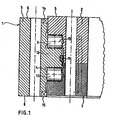
- a rotor blade bearing 1 with a high designed Kochrollungsiere It consists of two connecting elements 2, 3 in the form of concentric rings. Both rings 2, 3 have annularly distributed bores 4, 5 for passing through screws, bolts or the like, which are anchored to a rotor blade on the one hand, on the rotor hub on the other hand, ie. be screwed.
- the inner ring 2 is connected to the rotor blade, the outer ring 3 to the rotor hub.
- the two annular connecting elements 2, 3 are made of tempered steel, that is, they are tempered and thermally treated.
- the upper end faces 5, 6 of the two annular connecting elements 2, 3 are not in a common plane, but are offset by, for example, 5 to 15 mm from each other.
- the same is preferably true for the lower end faces 7, 8 of the two annular connecting elements 2, 3.
- the respective raised end face 5, 8 is connected to the adjacent part of Wind turbine - rotor blade or rotor hub - bolted.
- the respectively offset by a few millimeters end face 6, 7 of the other ring 2, 3 can therefore not along the unconnected part of the plant along.
- rollers 9, 10, 11 are used in the illustrated rotor blade bearing 1 by way of example, but this is not mandatory.
- the respective opposite raceways are located on the three sides of a recess formed in the opposite ring 2 of also approximately rectangular cross-section.
- the raceways are surface hardened, either by induction hardening or by flame hardening, to a depth of at least 1/20 of the respective roll diameter.
- rollers 9, 10 above and below the collar 12 have radially to the axis of rotation of the bearing 1 extending axes of rotation 13, the third row of rollers 11 on the outer surface of the collar 12, however, to the axis of rotation of the bearing 1 parallel axes of rotation.
- These rollers 11 have smaller diameters than the rollers 9, 10, for example, only half the diameter or less, preferably only one third of the diameter of the rollers 9, 10 or less, in particular only a quarter of the diameter of the rollers 9, 10 or less, so that the axial (static) load capacity of the bearing 1 is greater than the radial (static) transferable force.
- the rollers 9, 10 above and below the collar have a diameter of 15 mm or more.
- the gap 4 is sealed at each in the areas between the two upper end faces 5, 6 and between the two lower end faces 7, 8 by at least one seal 14, 15 and with a lubricant, especially grease, filled.
- a lubricant especially grease
- the gap 4 is completely filled with grease, which is possibly even pressed under increased pressure to ensure an optimal lubricating film between the rolling elements 9-11 on the one hand and the raceways on the other.
- the seals 14, 15 are preferably designed such that their sealing lips are pressed by an internal pressure in the gap 4 fixed to the respective opposite terminal element 2, 3.
- FIG Fig. 6 A conventional rotor blade bearing 31 is shown in FIG Fig. 6 for comparison purposes. It can be seen that it is designed as a double-row ball slewing connection with two annular, mutually concentric connection elements 32, 33 and a gap 34 lying between them.
- the upper two end faces 35, 36 may be slightly offset from each other; the two lower end faces 37, 38 are also slightly offset from each other, in the same direction, so that both annular connecting elements 32, 33 have identical or nearly identical, axial heights.
- the load capacities C a1 , C a2 ... C an are calculated for the rows with Z 1 , Z 2 ... Z n rollers according to the above equation for single row roller bearings.
- L 10 C a . ges / P a 10 / 3 .
- V L ⁇ 1 5 3 3 . 375 . ie, the expected life equivalent to at least more than three times that of a conventional rotor blade bearing; It increases rapidly by a slight increase in C a, and can easily reach values more than ten times that of a conventional rotor blade bearing.
- the angles of attack of one, several or all of the rotor blades 20 can be adjusted in such a way that, by interaction with the wind, they exert changed wind forces on the rotor 18 and thus on the nacelle 19 in order to counteract the fluctuations and / or vibrations.
- the respective rotor blade rotation angle about the rotor or main axis is taken into account; Therefore, a position or angle sensor should be arranged on the rotor or main shaft, so that the angular position of all rotor blades is known at any time.
- the tower 16 of a wind turbine 17 can also be excited to torsional or torsional vibrations about its vertical axis. This is especially triggered when the wind is not constantly blowing from the same direction, but turns more or less fast, as in Fig. 4 indicated, a plan view of a wind turbine 17.
- the wind - eg. In Frame of a gust - temporarily turned and now no longer meets perpendicular to the rotor blade plane, or is no longer parallel to the direction of the main rotor axis.
- the effect is that the wind force experienced by a rotor blade 20 depends not only on its height but also on its orientation to the changed wind direction: If a rotor blade 20 points straight against the wind direction v ⁇ , as in FIG Fig. 4 Rotor blade 20 shown below, it has a higher windage surface and therefore experiences a larger wind force F than an approximately opposite rotor blade, 20, which in contrast is partially shaded, for example, by the rotor hub 18 of the wind turbine 17th
- Even such torsional vibrations of the tower 16 can be counteracted by a suitable (anticyclical) control of the angle of attack of the rotor blades 20.
- the respective current wind direction is determined, for example, with a sensor for the wind direction, which is preferably located on top of the nacelle 19 of the wind turbine 17.
- the control and / or regulation concept according to the invention profits from the circumstance that the moment of inertia of a rotor blade 20 to be overcome during an adjustment of the rotor blade angle is much less than, for example, the moment of inertia of the unit to be overcome in a process of the nacelle 19 in another wind direction Gondola 19 and rotor 18 with rotor blades 20.
- FIG. 4 Yet another case is shown, namely a gusty wind that does not change with respect to its direction, but rather its magnitude, for example from v ⁇ 1 to v ⁇ 2 .
- This is detected by means of sensors which are not located directly on the wind turbine 17, but in their environment, wind farms, for example. On adjacent wind turbines 17, masts, buildings, etc.
- the wind turbine 17 can already experience before the arrival of a Windbö of this event and adjust the angles of attack of the rotor blades 20 so as to mitigate the arrival of the Bö normally connected thereto, sudden increase in wind power F or even compensate and thus completely or partially 16 from the tower 16 of the wind turbine ,
- the design of the rotor blade bearing 1 according to the invention allows a large number of structural loads to be kept away from the wind turbine tower 16, so that it fluctuates and oscillates far less than without a corresponding measure.
- the operating life of a wind turbine 17 can be significantly increased.
Landscapes
- Engineering & Computer Science (AREA)
- General Engineering & Computer Science (AREA)
- Mechanical Engineering (AREA)
- Life Sciences & Earth Sciences (AREA)
- Sustainable Development (AREA)
- Sustainable Energy (AREA)
- Chemical & Material Sciences (AREA)
- Combustion & Propulsion (AREA)
- Physics & Mathematics (AREA)
- Fluid Mechanics (AREA)
- Wind Motors (AREA)
Applications Claiming Priority (2)
| Application Number | Priority Date | Filing Date | Title |
|---|---|---|---|
| DE102008009740A DE102008009740A1 (de) | 2008-02-18 | 2008-02-18 | Windkraftanlage sowie Verfahren zum Betrieb derselben |
| PCT/EP2009/001076 WO2009103473A2 (de) | 2008-02-18 | 2009-02-16 | Windkraftanlage sowie verfahren zum betrieb derselben |
Publications (2)
| Publication Number | Publication Date |
|---|---|
| EP2304232A2 EP2304232A2 (de) | 2011-04-06 |
| EP2304232B1 true EP2304232B1 (de) | 2015-04-08 |
Family
ID=40874086
Family Applications (1)
| Application Number | Title | Priority Date | Filing Date |
|---|---|---|---|
| EP09713132.0A Not-in-force EP2304232B1 (de) | 2008-02-18 | 2009-02-16 | Verfahren zur auslegung einer windkraftanlage |
Country Status (6)
| Country | Link |
|---|---|
| US (1) | US8915715B2 (da) |
| EP (1) | EP2304232B1 (da) |
| DE (1) | DE102008009740A1 (da) |
| DK (1) | DK2304232T3 (da) |
| ES (1) | ES2541666T3 (da) |
| WO (1) | WO2009103473A2 (da) |
Cited By (2)
| Publication number | Priority date | Publication date | Assignee | Title |
|---|---|---|---|---|
| CN109715939A (zh) * | 2016-09-13 | 2019-05-03 | 福斯4X股份有限公司 | 用于确定风力涡轮机塔架上的载荷的方法和设备 |
| DE102018112017B3 (de) | 2018-05-18 | 2019-05-23 | Ibrahim Muhamad | Drehverbindung für ein Rotorblatt einer Windenergieanlage |
Families Citing this family (33)
| Publication number | Priority date | Publication date | Assignee | Title |
|---|---|---|---|---|
| DK2331813T3 (da) | 2008-09-10 | 2012-09-03 | Timken Co | Transmission til vindmølle |
| RU2523928C2 (ru) * | 2009-02-27 | 2014-07-27 | Снекма | Лопатки вентилятора с изменяемым углом установки |
| DK2535574T3 (da) * | 2010-02-08 | 2015-09-21 | Mitsubishi Heavy Ind Ltd | Vinddrevet strømgenerator og fremgangsmåde til styring af vingepitchregulering dertil |
| DE102010018255A1 (de) * | 2010-04-23 | 2011-10-27 | Imo Holding Gmbh | Dichtungsanordnung für Wälzlager |
| US9631605B2 (en) * | 2010-11-26 | 2017-04-25 | Vestas Wind Systems A/S | Pitch system for a wind turbine |
| DE102011008958A1 (de) * | 2011-01-19 | 2012-07-19 | Imo Holding Gmbh | Rotorlager für eine Windkraftanlage |
| DE102011000769A1 (de) * | 2011-02-16 | 2012-08-16 | Rothe Erde Gmbh | Axial-Radialwälzlager, insbesondere für die Lagerung von Rotorblättern an einer Windkraftanlage |
| JP6041861B2 (ja) | 2011-04-05 | 2016-12-14 | テュッセンクルップ ローテ エルデ ゲーエムベーハー | 油潤滑式減摩軸受 |
| EP2570655B1 (de) | 2011-09-16 | 2015-11-11 | IMO Holding GmbH | Vorrichtung zum aktiven Verstellen eines Blattes einer (Klein) windenergieanlage |
| DE202011105711U1 (de) | 2011-09-16 | 2011-11-04 | Imo Holding Gmbh | Kleinwindenergieanlage und Vorrichtung zum aktiven Verstellen eines Blattes einer (Klein)windenergieanlage |
| DE102011113372A1 (de) | 2011-09-16 | 2013-03-21 | Imo Holding Gmbh | Kleinwindenergieanlage und Vorrichtung zum aktiven Verstellen eines Blattes einer (Klein)windenergieanlage |
| EP2620639B1 (en) * | 2012-01-30 | 2016-01-27 | ALSTOM Renewable Technologies | A method for dampening oscillations in a wind turbine |
| JP6214564B2 (ja) * | 2012-02-07 | 2017-10-18 | アイエムオー ホールディング ジーエムビーエイチ | エネルギーシステムの逆回転可能な部品を取り付けるための機構 |
| DE102012004329B4 (de) * | 2012-02-07 | 2021-04-15 | Imo Holding Gmbh | Anordnung zur Lagerung von gegeneinander verdrehbaren Teilen einer Energieanlage |
| CN104335023A (zh) * | 2012-04-24 | 2015-02-04 | Skf公司 | 轴承监控方法和系统 |
| US9200619B2 (en) | 2012-08-07 | 2015-12-01 | General Electric Company | Wind turbine yaw or pitch bearing utilizing a threaded bearing surface |
| DE102012218484A1 (de) | 2012-10-10 | 2014-04-10 | Wobben Properties Gmbh | Verfahren zum Betreiben einer Windenergieanlage |
| US10787195B2 (en) * | 2013-05-22 | 2020-09-29 | Jtekt Corporation | Electric power steering system |
| DE102013215962A1 (de) * | 2013-08-13 | 2015-03-12 | Schaeffler Technologies AG & Co. KG | Rundtischlager |
| US20160356266A1 (en) * | 2015-06-03 | 2016-12-08 | General Electric Company | System and Method for Reducing Torsional Movement in a Wind Turbine Tower |
| DE102016203269A1 (de) * | 2016-02-29 | 2017-08-31 | Innogy Se | Windkraftanlage mit verbesserter Rotorblattverschraubung |
| EP3225838A1 (en) * | 2016-03-30 | 2017-10-04 | Siemens Aktiengesellschaft | Method and arrangement for performing a wind direction measurement |
| DE102016116476A1 (de) * | 2016-09-02 | 2018-03-08 | Thyssenkrupp Ag | Wälzlager und Verfahren zum Abdichten eines Wälzlagers |
| DE102017206246A1 (de) * | 2017-04-11 | 2018-10-11 | Thyssenkrupp Ag | Lageranordnung zur Lagerung eines Rotorblatts einer Windenergieanlage |
| CN107657122B (zh) * | 2017-09-29 | 2021-05-11 | 无锡三立轴承股份有限公司 | 机床主轴圆柱滚子轴承设计方法 |
| DE102017219823A1 (de) * | 2017-11-08 | 2019-05-09 | Aktiebolaget Skf | Wälzlager zum Unterstützen einer radialen Verformung des Wälzlagers und rotierende Anordnung, welche ein solches Wälzlager aufweist |
| CN108374835A (zh) * | 2018-04-25 | 2018-08-07 | 成都天马铁路轴承有限公司 | 风电三排圆柱滚子变桨轴承 |
| ES2935465T3 (es) * | 2018-04-30 | 2023-03-07 | Vestas Wind Sys As | Rotor para una turbina eólica con una unidad de cojinete de regulación de paso |
| EP3821125B1 (en) | 2018-07-11 | 2023-08-30 | Vestas Wind Systems A/S | Method and system for controlling a wind turbine to reduce nacelle vibration |
| ES3035804T3 (en) * | 2018-12-21 | 2025-09-09 | Vestas Wind Sys As | Wind turbine control based on optimising and non-optimising controller routines |
| CN111985110A (zh) * | 2020-08-24 | 2020-11-24 | 国电联合动力技术有限公司 | 风电机组偏航轴承寿命计算方法及装置 |
| CN112648137B (zh) * | 2021-01-19 | 2021-12-24 | 兰州理工大学 | 一种风电叶片多质点串联速度放大型减振装置及连接方法 |
| CN114757071B (zh) * | 2022-04-11 | 2024-08-09 | 西安交通大学 | 一种基于振动参数周期预测叶盘振动节径数的方法 |
Citations (4)
| Publication number | Priority date | Publication date | Assignee | Title |
|---|---|---|---|---|
| US3791706A (en) * | 1971-06-09 | 1974-02-12 | Formmet Corp | Forged ring structure of multiple cast metals |
| DE3909664C1 (en) * | 1989-03-23 | 1990-08-30 | Hoesch Ag, 4600 Dortmund, De | Centre-free roller revolving connection |
| EP1132614A2 (de) * | 2000-03-09 | 2001-09-12 | Enron Wind GmbH | Regelungssystem für eine Windkraftanlage |
| WO2007104306A1 (en) * | 2006-03-16 | 2007-09-20 | Vestas Wind Systems A/S | A method and control system for reducing the fatigue loads in the components of a wind turbine subjected to asymmetrical loading of the rotor plane |
Family Cites Families (13)
| Publication number | Priority date | Publication date | Assignee | Title |
|---|---|---|---|---|
| FR2180192A5 (da) * | 1972-04-12 | 1973-11-23 | Ugine Aciers | |
| DE29715249U1 (de) | 1997-08-25 | 1998-12-24 | Institut für Solare Energieversorgungstechnik Verein an der Universität Gesamthochschule Kassel eV, 34119 Kassel | Windenergieanlage |
| ES2228121T3 (es) | 1999-11-03 | 2005-04-01 | Vestas Wind Systems A/S | Procedimiento de control de la operacion de una turbina electrica y turbina electrica para usarse en dicho procedimiento. |
| DE10016912C1 (de) | 2000-04-05 | 2001-12-13 | Aerodyn Eng Gmbh | Turmeigenfrequenzabhängige Betriebsführung von Offshore-Windenergieanlagen |
| DE10113038C2 (de) | 2001-03-17 | 2003-04-10 | Aloys Wobben | Turmschwingungsüberwachung |
| DK177602B1 (da) * | 2004-01-16 | 2013-11-18 | Lm Wind Power As | Overvågning af driften af et vindenergianlæg |
| US7309930B2 (en) * | 2004-09-30 | 2007-12-18 | General Electric Company | Vibration damping system and method for variable speed wind turbines |
| ES2552691T3 (es) * | 2004-12-30 | 2015-12-01 | Vestas Wind Systems A/S | Turbina eólica que comprende un sistema de control de redundancia multiplicada y método para controlar una turbina eólica |
| FI117352B (fi) | 2005-03-09 | 2006-09-15 | Winwind Oy | Menetelmä tuulivoimalan roottorin pysäyttämiseksi |
| DE102005026141C5 (de) | 2005-06-06 | 2025-03-27 | Imo Momentenlager Gmbh | Windkraftanlage mit einer Lagereinheit für ein langgestrecktes Rotorblatt |
| EP1907692B2 (en) | 2005-07-05 | 2022-12-07 | Vestas Wind Systems A/S | A wind turbine pitch bearing, and use hereof |
| EP1907694B2 (en) | 2005-07-08 | 2016-01-20 | Vestas Wind Systems A/S | A wind turbine, a hub for a wind turbine and use hereof |
| ATE447117T1 (de) | 2006-01-23 | 2009-11-15 | Vestas Wind Sys As | Lager, windturbine und verfahren zur herstellung eines lagers |
-
2008
- 2008-02-18 DE DE102008009740A patent/DE102008009740A1/de not_active Ceased
-
2009
- 2009-02-16 US US12/735,792 patent/US8915715B2/en not_active Expired - Fee Related
- 2009-02-16 ES ES09713132.0T patent/ES2541666T3/es active Active
- 2009-02-16 EP EP09713132.0A patent/EP2304232B1/de not_active Not-in-force
- 2009-02-16 DK DK09713132.0T patent/DK2304232T3/da active
- 2009-02-16 WO PCT/EP2009/001076 patent/WO2009103473A2/de not_active Ceased
Patent Citations (4)
| Publication number | Priority date | Publication date | Assignee | Title |
|---|---|---|---|---|
| US3791706A (en) * | 1971-06-09 | 1974-02-12 | Formmet Corp | Forged ring structure of multiple cast metals |
| DE3909664C1 (en) * | 1989-03-23 | 1990-08-30 | Hoesch Ag, 4600 Dortmund, De | Centre-free roller revolving connection |
| EP1132614A2 (de) * | 2000-03-09 | 2001-09-12 | Enron Wind GmbH | Regelungssystem für eine Windkraftanlage |
| WO2007104306A1 (en) * | 2006-03-16 | 2007-09-20 | Vestas Wind Systems A/S | A method and control system for reducing the fatigue loads in the components of a wind turbine subjected to asymmetrical loading of the rotor plane |
Cited By (4)
| Publication number | Priority date | Publication date | Assignee | Title |
|---|---|---|---|---|
| CN109715939A (zh) * | 2016-09-13 | 2019-05-03 | 福斯4X股份有限公司 | 用于确定风力涡轮机塔架上的载荷的方法和设备 |
| DE102018112017B3 (de) | 2018-05-18 | 2019-05-23 | Ibrahim Muhamad | Drehverbindung für ein Rotorblatt einer Windenergieanlage |
| WO2019219252A1 (de) | 2018-05-18 | 2019-11-21 | Ibrahim Muhamad | Drehverbindung für ein rotorblatt einer windenergieanlage |
| US11566599B2 (en) | 2018-05-18 | 2023-01-31 | Ibrahim Muhamad | Rotary connection for a rotor blade of a wind turbine |
Also Published As
| Publication number | Publication date |
|---|---|
| US8915715B2 (en) | 2014-12-23 |
| US20110115233A1 (en) | 2011-05-19 |
| DE102008009740A1 (de) | 2009-08-20 |
| DK2304232T3 (da) | 2015-07-13 |
| EP2304232A2 (de) | 2011-04-06 |
| WO2009103473A2 (de) | 2009-08-27 |
| ES2541666T3 (es) | 2015-07-23 |
| WO2009103473A3 (de) | 2010-02-18 |
Similar Documents
| Publication | Publication Date | Title |
|---|---|---|
| EP2304232B1 (de) | Verfahren zur auslegung einer windkraftanlage | |
| EP1891327B1 (de) | Windkraftanlage mit einer rotorblattlagerung sowie verfahren zum betrieb einer derartigen windkraftanlage | |
| EP1266137B1 (de) | Lagerung eines verstellbaren rotorblatts einer windenergieanlage | |
| EP0998634B1 (de) | Windenergieanlage | |
| EP3343030B1 (de) | Vorrichtung und verfahren zur überwachung eines blattlagers einer windkraftanlage | |
| EP3896278B1 (de) | Vertikale windkraftanlage sowie verfahren zum betrieb einer solchen anlage | |
| EP3645869B1 (de) | Vertikalwindkraftanlage mit koaxialem pitchmotor sowie bausatz für selbige und verfahren für ihren betrieb | |
| EP3645868B1 (de) | Vertikalwindkraftanlage mit geregeltem schnelllaufverhalten sowie bausatz für selbige und verfahren für ihren betrieb | |
| EP2795115B1 (de) | Blatt- oder maschinenhauslager einer windkraftanlage | |
| EP2914844B1 (de) | Verfahren zum betreiben einer windenergieanlage, windenergieanlage und steuerungseinrichtung für eine windenergieanlage | |
| DE102015218228A1 (de) | Rotorwellenanordnung für Windrad | |
| WO2008152083A1 (de) | Windkraftanlage | |
| EP2462344B1 (de) | Windenergieanlage mit einrichtung zur lastminimierung | |
| WO2019002549A1 (de) | Vertikalwindkraftanlage mit rotorblatttragendem pitchmotor sowie bausatz für selbige und verfahren für ihren betrieb | |
| EP2507522B1 (de) | Kugellager | |
| EP3947995B1 (de) | Grosswälzlager | |
| DE112014004779T5 (de) | Lageranordnung | |
| EP4242453A1 (de) | Triebstranglagerungsanordnung mit momentenabstützung sowie damit ausgestattetes industriegetriebe sowie verfahren zum einstellen einer triebstranglagerungsanordnung und verwendung | |
| DE102019217534A1 (de) | Rotorlager für eine Windenergieanlage und Windenergieanlage | |
| EP3276160B1 (de) | Lagermodul zur verstellung eines anstellwinkels eines rotorblatts in einem unterwasserkraftwerk | |
| EP4405593B1 (de) | Rotorlagereinheit für eine windenergieanlage und verfahren zur einstellung der vorspannung in einer rotorlagereinheit | |
| EP2570655B1 (de) | Vorrichtung zum aktiven Verstellen eines Blattes einer (Klein) windenergieanlage | |
| WO2010037371A1 (de) | Drehverbindung für eine windkraftmaschine, insbesondere doppeltes, mehrreihiges wälzlager mit drei konzentrischen lagerringen | |
| DE102013006281B4 (de) | Antriebs- oder Verstellvorrichtung | |
| DE102005063678B3 (de) | Verfahren zum Betrieb einer Windkraftanlage mit einer Lagereinheit für ein langgestrecktes Rotorblatt |
Legal Events
| Date | Code | Title | Description |
|---|---|---|---|
| PUAI | Public reference made under article 153(3) epc to a published international application that has entered the european phase |
Free format text: ORIGINAL CODE: 0009012 |
|
| 17P | Request for examination filed |
Effective date: 20100917 |
|
| AK | Designated contracting states |
Kind code of ref document: A2 Designated state(s): AT BE BG CH CY CZ DE DK EE ES FI FR GB GR HR HU IE IS IT LI LT LU LV MC MK MT NL NO PL PT RO SE SI SK TR |
|
| AX | Request for extension of the european patent |
Extension state: AL BA RS |
|
| DAX | Request for extension of the european patent (deleted) | ||
| 17Q | First examination report despatched |
Effective date: 20120913 |
|
| GRAP | Despatch of communication of intention to grant a patent |
Free format text: ORIGINAL CODE: EPIDOSNIGR1 |
|
| INTG | Intention to grant announced |
Effective date: 20140723 |
|
| GRAS | Grant fee paid |
Free format text: ORIGINAL CODE: EPIDOSNIGR3 |
|
| GRAP | Despatch of communication of intention to grant a patent |
Free format text: ORIGINAL CODE: EPIDOSNIGR1 |
|
| INTG | Intention to grant announced |
Effective date: 20150119 |
|
| GRAA | (expected) grant |
Free format text: ORIGINAL CODE: 0009210 |
|
| AK | Designated contracting states |
Kind code of ref document: B1 Designated state(s): AT BE BG CH CY CZ DE DK EE ES FI FR GB GR HR HU IE IS IT LI LT LU LV MC MK MT NL NO PL PT RO SE SI SK TR |
|
| REG | Reference to a national code |
Ref country code: GB Ref legal event code: FG4D Free format text: NOT ENGLISH |
|
| REG | Reference to a national code |
Ref country code: CH Ref legal event code: EP |
|
| REG | Reference to a national code |
Ref country code: IE Ref legal event code: FG4D Free format text: LANGUAGE OF EP DOCUMENT: GERMAN |
|
| REG | Reference to a national code |
Ref country code: AT Ref legal event code: REF Ref document number: 720800 Country of ref document: AT Kind code of ref document: T Effective date: 20150515 |
|
| REG | Reference to a national code |
Ref country code: DE Ref legal event code: R096 Ref document number: 502009010878 Country of ref document: DE Effective date: 20150521 |
|
| REG | Reference to a national code |
Ref country code: DK Ref legal event code: T3 Effective date: 20150710 |
|
| REG | Reference to a national code |
Ref country code: ES Ref legal event code: FG2A Ref document number: 2541666 Country of ref document: ES Kind code of ref document: T3 Effective date: 20150723 |
|
| REG | Reference to a national code |
Ref country code: NL Ref legal event code: VDEP Effective date: 20150408 |
|
| REG | Reference to a national code |
Ref country code: LT Ref legal event code: MG4D |
|
| PG25 | Lapsed in a contracting state [announced via postgrant information from national office to epo] |
Ref country code: NL Free format text: LAPSE BECAUSE OF FAILURE TO SUBMIT A TRANSLATION OF THE DESCRIPTION OR TO PAY THE FEE WITHIN THE PRESCRIBED TIME-LIMIT Effective date: 20150408 |
|
| PG25 | Lapsed in a contracting state [announced via postgrant information from national office to epo] |
Ref country code: HR Free format text: LAPSE BECAUSE OF FAILURE TO SUBMIT A TRANSLATION OF THE DESCRIPTION OR TO PAY THE FEE WITHIN THE PRESCRIBED TIME-LIMIT Effective date: 20150408 Ref country code: LT Free format text: LAPSE BECAUSE OF FAILURE TO SUBMIT A TRANSLATION OF THE DESCRIPTION OR TO PAY THE FEE WITHIN THE PRESCRIBED TIME-LIMIT Effective date: 20150408 Ref country code: PT Free format text: LAPSE BECAUSE OF FAILURE TO SUBMIT A TRANSLATION OF THE DESCRIPTION OR TO PAY THE FEE WITHIN THE PRESCRIBED TIME-LIMIT Effective date: 20150810 Ref country code: FI Free format text: LAPSE BECAUSE OF FAILURE TO SUBMIT A TRANSLATION OF THE DESCRIPTION OR TO PAY THE FEE WITHIN THE PRESCRIBED TIME-LIMIT Effective date: 20150408 Ref country code: NO Free format text: LAPSE BECAUSE OF FAILURE TO SUBMIT A TRANSLATION OF THE DESCRIPTION OR TO PAY THE FEE WITHIN THE PRESCRIBED TIME-LIMIT Effective date: 20150708 |
|
| REG | Reference to a national code |
Ref country code: SK Ref legal event code: T3 Ref document number: E 19081 Country of ref document: SK |
|
| PG25 | Lapsed in a contracting state [announced via postgrant information from national office to epo] |
Ref country code: GR Free format text: LAPSE BECAUSE OF FAILURE TO SUBMIT A TRANSLATION OF THE DESCRIPTION OR TO PAY THE FEE WITHIN THE PRESCRIBED TIME-LIMIT Effective date: 20150709 Ref country code: LV Free format text: LAPSE BECAUSE OF FAILURE TO SUBMIT A TRANSLATION OF THE DESCRIPTION OR TO PAY THE FEE WITHIN THE PRESCRIBED TIME-LIMIT Effective date: 20150408 Ref country code: IS Free format text: LAPSE BECAUSE OF FAILURE TO SUBMIT A TRANSLATION OF THE DESCRIPTION OR TO PAY THE FEE WITHIN THE PRESCRIBED TIME-LIMIT Effective date: 20150808 |
|
| REG | Reference to a national code |
Ref country code: DE Ref legal event code: R097 Ref document number: 502009010878 Country of ref document: DE |
|
| PG25 | Lapsed in a contracting state [announced via postgrant information from national office to epo] |
Ref country code: EE Free format text: LAPSE BECAUSE OF FAILURE TO SUBMIT A TRANSLATION OF THE DESCRIPTION OR TO PAY THE FEE WITHIN THE PRESCRIBED TIME-LIMIT Effective date: 20150408 |
|
| PLBE | No opposition filed within time limit |
Free format text: ORIGINAL CODE: 0009261 |
|
| STAA | Information on the status of an ep patent application or granted ep patent |
Free format text: STATUS: NO OPPOSITION FILED WITHIN TIME LIMIT |
|
| REG | Reference to a national code |
Ref country code: FR Ref legal event code: PLFP Year of fee payment: 8 |
|
| PG25 | Lapsed in a contracting state [announced via postgrant information from national office to epo] |
Ref country code: RO Free format text: LAPSE BECAUSE OF NON-PAYMENT OF DUE FEES Effective date: 20150408 Ref country code: PL Free format text: LAPSE BECAUSE OF FAILURE TO SUBMIT A TRANSLATION OF THE DESCRIPTION OR TO PAY THE FEE WITHIN THE PRESCRIBED TIME-LIMIT Effective date: 20150408 Ref country code: CZ Free format text: LAPSE BECAUSE OF FAILURE TO SUBMIT A TRANSLATION OF THE DESCRIPTION OR TO PAY THE FEE WITHIN THE PRESCRIBED TIME-LIMIT Effective date: 20150408 |
|
| 26N | No opposition filed |
Effective date: 20160111 |
|
| PGFP | Annual fee paid to national office [announced via postgrant information from national office to epo] |
Ref country code: DE Payment date: 20160218 Year of fee payment: 8 Ref country code: ES Payment date: 20160223 Year of fee payment: 8 Ref country code: DK Payment date: 20160222 Year of fee payment: 8 Ref country code: IT Payment date: 20160222 Year of fee payment: 8 Ref country code: SK Payment date: 20160205 Year of fee payment: 8 |
|
| PG25 | Lapsed in a contracting state [announced via postgrant information from national office to epo] |
Ref country code: SI Free format text: LAPSE BECAUSE OF FAILURE TO SUBMIT A TRANSLATION OF THE DESCRIPTION OR TO PAY THE FEE WITHIN THE PRESCRIBED TIME-LIMIT Effective date: 20150408 Ref country code: BE Free format text: LAPSE BECAUSE OF NON-PAYMENT OF DUE FEES Effective date: 20160229 |
|
| PGFP | Annual fee paid to national office [announced via postgrant information from national office to epo] |
Ref country code: FR Payment date: 20160222 Year of fee payment: 8 Ref country code: GB Payment date: 20160222 Year of fee payment: 8 |
|
| PG25 | Lapsed in a contracting state [announced via postgrant information from national office to epo] |
Ref country code: MC Free format text: LAPSE BECAUSE OF FAILURE TO SUBMIT A TRANSLATION OF THE DESCRIPTION OR TO PAY THE FEE WITHIN THE PRESCRIBED TIME-LIMIT Effective date: 20150408 Ref country code: LU Free format text: LAPSE BECAUSE OF FAILURE TO SUBMIT A TRANSLATION OF THE DESCRIPTION OR TO PAY THE FEE WITHIN THE PRESCRIBED TIME-LIMIT Effective date: 20160216 |
|
| REG | Reference to a national code |
Ref country code: CH Ref legal event code: PL |
|
| PG25 | Lapsed in a contracting state [announced via postgrant information from national office to epo] |
Ref country code: CH Free format text: LAPSE BECAUSE OF NON-PAYMENT OF DUE FEES Effective date: 20160229 Ref country code: LI Free format text: LAPSE BECAUSE OF NON-PAYMENT OF DUE FEES Effective date: 20160229 |
|
| REG | Reference to a national code |
Ref country code: IE Ref legal event code: MM4A |
|
| PG25 | Lapsed in a contracting state [announced via postgrant information from national office to epo] |
Ref country code: IE Free format text: LAPSE BECAUSE OF NON-PAYMENT OF DUE FEES Effective date: 20160216 |
|
| REG | Reference to a national code |
Ref country code: AT Ref legal event code: MM01 Ref document number: 720800 Country of ref document: AT Kind code of ref document: T Effective date: 20160216 |
|
| PG25 | Lapsed in a contracting state [announced via postgrant information from national office to epo] |
Ref country code: AT Free format text: LAPSE BECAUSE OF NON-PAYMENT OF DUE FEES Effective date: 20160216 |
|
| PG25 | Lapsed in a contracting state [announced via postgrant information from national office to epo] |
Ref country code: SE Free format text: LAPSE BECAUSE OF FAILURE TO SUBMIT A TRANSLATION OF THE DESCRIPTION OR TO PAY THE FEE WITHIN THE PRESCRIBED TIME-LIMIT Effective date: 20150408 |
|
| PG25 | Lapsed in a contracting state [announced via postgrant information from national office to epo] |
Ref country code: MT Free format text: LAPSE BECAUSE OF FAILURE TO SUBMIT A TRANSLATION OF THE DESCRIPTION OR TO PAY THE FEE WITHIN THE PRESCRIBED TIME-LIMIT Effective date: 20150408 |
|
| REG | Reference to a national code |
Ref country code: DE Ref legal event code: R119 Ref document number: 502009010878 Country of ref document: DE |
|
| REG | Reference to a national code |
Ref country code: DK Ref legal event code: EBP Effective date: 20170228 |
|
| GBPC | Gb: european patent ceased through non-payment of renewal fee |
Effective date: 20170216 |
|
| PG25 | Lapsed in a contracting state [announced via postgrant information from national office to epo] |
Ref country code: SK Free format text: LAPSE BECAUSE OF NON-PAYMENT OF DUE FEES Effective date: 20170216 |
|
| REG | Reference to a national code |
Ref country code: SK Ref legal event code: MM4A Ref document number: E 19081 Country of ref document: SK Effective date: 20170216 |
|
| REG | Reference to a national code |
Ref country code: FR Ref legal event code: ST Effective date: 20171031 |
|
| PG25 | Lapsed in a contracting state [announced via postgrant information from national office to epo] |
Ref country code: DK Free format text: LAPSE BECAUSE OF NON-PAYMENT OF DUE FEES Effective date: 20170228 Ref country code: FR Free format text: LAPSE BECAUSE OF NON-PAYMENT OF DUE FEES Effective date: 20170228 Ref country code: DE Free format text: LAPSE BECAUSE OF NON-PAYMENT OF DUE FEES Effective date: 20170901 |
|
| PG25 | Lapsed in a contracting state [announced via postgrant information from national office to epo] |
Ref country code: IT Free format text: LAPSE BECAUSE OF NON-PAYMENT OF DUE FEES Effective date: 20170216 Ref country code: GB Free format text: LAPSE BECAUSE OF NON-PAYMENT OF DUE FEES Effective date: 20170216 |
|
| PG25 | Lapsed in a contracting state [announced via postgrant information from national office to epo] |
Ref country code: CY Free format text: LAPSE BECAUSE OF FAILURE TO SUBMIT A TRANSLATION OF THE DESCRIPTION OR TO PAY THE FEE WITHIN THE PRESCRIBED TIME-LIMIT Effective date: 20150408 Ref country code: HU Free format text: LAPSE BECAUSE OF FAILURE TO SUBMIT A TRANSLATION OF THE DESCRIPTION OR TO PAY THE FEE WITHIN THE PRESCRIBED TIME-LIMIT; INVALID AB INITIO Effective date: 20090216 |
|
| PG25 | Lapsed in a contracting state [announced via postgrant information from national office to epo] |
Ref country code: TR Free format text: LAPSE BECAUSE OF FAILURE TO SUBMIT A TRANSLATION OF THE DESCRIPTION OR TO PAY THE FEE WITHIN THE PRESCRIBED TIME-LIMIT Effective date: 20150408 Ref country code: MK Free format text: LAPSE BECAUSE OF FAILURE TO SUBMIT A TRANSLATION OF THE DESCRIPTION OR TO PAY THE FEE WITHIN THE PRESCRIBED TIME-LIMIT Effective date: 20150408 |
|
| REG | Reference to a national code |
Ref country code: ES Ref legal event code: FD2A Effective date: 20180710 |
|
| PG25 | Lapsed in a contracting state [announced via postgrant information from national office to epo] |
Ref country code: BG Free format text: LAPSE BECAUSE OF FAILURE TO SUBMIT A TRANSLATION OF THE DESCRIPTION OR TO PAY THE FEE WITHIN THE PRESCRIBED TIME-LIMIT Effective date: 20150408 |
|
| PG25 | Lapsed in a contracting state [announced via postgrant information from national office to epo] |
Ref country code: ES Free format text: LAPSE BECAUSE OF NON-PAYMENT OF DUE FEES Effective date: 20170217 |