EP2304123B1 - A modular system for a facade structure - Google Patents
A modular system for a facade structure Download PDFInfo
- Publication number
- EP2304123B1 EP2304123B1 EP09776872.5A EP09776872A EP2304123B1 EP 2304123 B1 EP2304123 B1 EP 2304123B1 EP 09776872 A EP09776872 A EP 09776872A EP 2304123 B1 EP2304123 B1 EP 2304123B1
- Authority
- EP
- European Patent Office
- Prior art keywords
- panels
- panel
- upstanding
- flanges
- intermediate portion
- Prior art date
- Legal status (The legal status is an assumption and is not a legal conclusion. Google has not performed a legal analysis and makes no representation as to the accuracy of the status listed.)
- Active
Links
Images




Classifications
-
- E—FIXED CONSTRUCTIONS
- E04—BUILDING
- E04F—FINISHING WORK ON BUILDINGS, e.g. STAIRS, FLOORS
- E04F13/00—Coverings or linings, e.g. for walls or ceilings
- E04F13/07—Coverings or linings, e.g. for walls or ceilings composed of covering or lining elements; Sub-structures therefor; Fastening means therefor
- E04F13/08—Coverings or linings, e.g. for walls or ceilings composed of covering or lining elements; Sub-structures therefor; Fastening means therefor composed of a plurality of similar covering or lining elements
- E04F13/0801—Separate fastening elements
- E04F13/0803—Separate fastening elements with load-supporting elongated furring elements between wall and covering elements
- E04F13/081—Separate fastening elements with load-supporting elongated furring elements between wall and covering elements with additional fastening elements between furring elements and covering elements
- E04F13/0812—Separate fastening elements with load-supporting elongated furring elements between wall and covering elements with additional fastening elements between furring elements and covering elements fixed by means of spring action
-
- E—FIXED CONSTRUCTIONS
- E04—BUILDING
- E04F—FINISHING WORK ON BUILDINGS, e.g. STAIRS, FLOORS
- E04F13/00—Coverings or linings, e.g. for walls or ceilings
- E04F13/07—Coverings or linings, e.g. for walls or ceilings composed of covering or lining elements; Sub-structures therefor; Fastening means therefor
- E04F13/08—Coverings or linings, e.g. for walls or ceilings composed of covering or lining elements; Sub-structures therefor; Fastening means therefor composed of a plurality of similar covering or lining elements
- E04F13/12—Coverings or linings, e.g. for walls or ceilings composed of covering or lining elements; Sub-structures therefor; Fastening means therefor composed of a plurality of similar covering or lining elements of metal or with an outer layer of metal or enameled metal
Definitions
- the present invention relates to a modular system for a façade structure for a building comprising panels and panel retaining elements for mounting the panels to the building.
- the invention also relates to a façade structure made using said modular system.
- BE900278 discloses an example of such a clamp for mounting panels to a wall or ceiling.
- the interlock is frequently achieved by using the male and female principle.
- WO00/23672 shows examples of covering systems utilising this male and female interlock.
- the construction of such buildings usually starts with erecting a framework comprising building elements to which the metal panels, for instance for the roof or façade, are attached.
- the interlocking system requires starting the attachment of the panels at a lower level and working upwards or the other way around. In all cases the next panel firmly locks the preceding panel in place.
- a disadvantage of the application of said panels is that when an intermediate panel needs to be replaced, for instance when it is damaged, these panels can only be replaced without destroying the panel by removing the other panels which were installed after the damaged panel are removed as well.
- the alternative of cutting the intermediate damaged panel and/or destroying the points of suspension of the damaged panel allows the panel to be removed without the need to remove other panels. Afterwards, the points of suspension need to be repaired. This is a difficult and time-consuming operation.
- a modular system for a façade structure for a building comprising panels and panel retaining elements for mounting the panels to the building
- said panels 1 comprise an intermediate portion 2 extending between two upstanding flanges 3a,3b located on opposite edges 2a,2b of the intermediate portion 2 and wherein the free ends 4a,4b of the upstanding flanges 3a,3b are bent so as to extend towards the back side 2f of the intermediate portion of the panel 1 thereby forming substantially v- or u-shaped flanges and wherein the free ends 4a,4b of the bent upstanding flanged do not touch the back side 2f of the intermediate portion 2, and wherein said panel retaining elements 5 comprise a base portion 6 for securing the retaining element to the building and at least one upstanding flange 7, wherein the upstanding flange 7 is provided with recesses 8a,8b, and which recesses are provided with securing notches 9a,9b so as allow mounting the panels to the
- the mounting of the panels preferably occurs by hanging the upper upstanding flange part of a panel in the recesses 8b, allowing it to hang onto the securing notch 9b, and then clicking the lower upstanding flange into the recess 8a, allowing it to be secured by the securing notch 9a.
- the panels may be mounted by pressing the two upstanding flanges of one panel into the recesses and behind securing notches simultaneously. It is important to note that there is no need to mount two adjoining panels simultaneously by clicking the flanges of the two adjoining panels into the recesses of a mounting bracket simultaneously. The clicking in place of the flange of one panel into the recess of a mounting bracket can be done before the hanging in place of the adjoining panel in the other recess of said mounting bracket.
- the flexing of the intermediate portion and the elastic resistance of the flanges will exert an inwardly directed force which will allow in the bent-away free ends of the upstanding flanges on the panel as one-way beards which are initially pressed in the recesses of the retaining element, and the spring-back of the flanges will ensure that the free edges hook behind the securing notches in the retaining elements.
- the deformation of the upstanding flanges during mounting is preferably an elastic deformation only.
- the intermediate portion of the panel is preferably rectangular in shape, because this way the panels are cheapest and more or less interchangeable.
- the opposite edges 2a,2b of the intermediate portion of adjoining panels abut, so as to achieve a snug fit between two adjoining panels.
- the opposite edges with the upstanding flanges are defined to be in the width direction of the panel, whereas the distance between the two upstanding flanges on one panel is defined as the height direction of the panel.
- the recesses may have a substantially complementary shape to the shape of the substantially v- or u-shaped flanges of the panels.
- the securing notches are elongated so as to create a slot-shaped or slit-shaped recess to receive the free ends of the upstanding flanges.
- the free ends of the upstanding flanges abut the securing notches of the recesses in the retaining elements head-on, i.e. the extremity of the free end touches the securing notch when a pulling force is exerted on the panel.
- the recesses are slot- or slit-shaped as a result of the elongation of the securing notches.
- the panels may comprise a perforated or mesh portion in the intermediate portion.
- the intermediate portion is preferably flat to produce a smooth façade, it is also possible to provide the intermediate portion with beads, stiffening ribs, micro lines or ridges. This may have a technical reason, e.g. to increase stiffness of the panel, or an aesthetical reason.
- the angle between one of the upstanding flanges and the intermediate portion of the panels is smaller than 90°.
- the panels are mounted on a vertical or tilted surface (i.e. non-horizontal), the panels are mounted such that the angle between the bottom flange and the intermediate portion is the acute angle, and the angle between the top flange and the intermediate portion is the obtuse angle.
- the angle between one of the upstanding flanges and the intermediate portion of the panels is larger than 90°.
- the angle between one of the upstanding flanges and the intermediate portion of the panels is smaller than 90° and the angle between the other upstanding flange and the intermediate portion of the panel is larger than 90°.
- one, more or all of the retaining element 5 comprise two upstanding flanges 7a,7b, wherein both upstanding flanges are provided with recesses 8a,8b which are substantially complementary to the shape of the substantially v- or u-shaped flanges of the panel 1, and which recesses 8a,8b are provided with securing notches 9a,9b .
- This embodiment allows an even more secure mounting of the panel into the retaining element by using both upstanding flanges of the retaining element to hold the upstanding flange of one panel, or it allows two neighbouring panels to be mounted, one using the one upstanding flange of the retaining element, and the neighbouring panel in the other upstanding flange.
- the upstanding flanges 3a,3b of the panels are not perpendicular to the intermediate portion 2 when the panel is seen in cross section along a line perpendicular to the edges 2a,2b, but wherein the angle formed by the intermediate portion and the first upstanding flange 36 is ⁇ °, and the angle formed by the intermediate portion and the second upstanding flange 3a is (180-(alpha + beta))°.
- the tilted upstanding flanges result in a tilted gap between two adjoining panels, particularly when mounted vertically, which prevents our counteracts water to seep through the gap towards the building or the support structure.
- the angle between the two adjoining flanges, ⁇ is 0 in this case.
- the angle a is sharp, i.e. less than 90° to avoid water permeating through the gap between two adjoining upstanding flanges of two adjoining panels.
- this embodiment will also comprise panels wherein ⁇ is not 0.
- This widening gap effectively counteracts the capillary effect that such a gap may have, and penetration of moisture through the gap is reduced or prevented.
- the preferably downward sloping of the gap as illustrated in figure 3 counteracts penetration of moisture as well as the penetration of wind driven rain. Since the sharp angle between the intermediate portion 2 and 3b of one panel is defined as a, the obtuse angle between intermediate portion 2 and 3a of the adjoining panel is 180-( ⁇ + ⁇ ).
- ⁇ is larger than 5° because it allows quick and precise mounting of the panels. It was found that ⁇ is preferably larger than 5°. It is preferable that the angle is not larger than 25°. In a preferred embodiment the angle is between 10 and 20°, e.g. 15°.
- the panels are made from sheet material of steel, a steel alloy, aluminium or an aluminium alloy, preferably by roll-forming, and wherein the panels are optionally coated with coating layers providing the panels with corrosion protection and/or colour and/or texture.
- a suitable thickness of the panels is between 0.5 and 2.5 mm, e.g. about 1 mm.
- the panels may be produced by simple bending or press-braking, but preferably by roll-forming.
- a dedicated roll-former By using a dedicated roll-former, the panels can be produced on the erection site of a building. Such a dedicated roll-former may be transported to the erection site in a standard transport- or sea-container
- a plurality of panel retaining elements is mounted onto the building and adjoining panels are snapped into the recesses 8a,8b of the retaining elements and wherein the upstanding flange 3a of a first panel and the upstanding flange 3b of a second panel longitudinally adjoin so as to allow mounting the adjoining panels to the building by snapping the adjoining v- or u-shaped flanges of the panels into the corresponding recesses 8a,8b in the upstanding flanges 7 of one or more retaining elements 5.
- Longitudinal adjoining means that the edge 2a of one panel adjoins the edge 2b of the adjoining panel.
- the panel retaining elements may be mounted to the building individually as single brackets, or as a part of a rail comprising a plurality of brackets over the length of the rail.
- the plurality of brackets over the length of the rail may be individually premounted single brackets, or the rail may be provided with recesses to receive and hold the upstanding flanges of the panels (item 5 in Figure 11a ).
- the single brackets or the rail comprising the plurality of brackets are mounted to the building using a further U-shaped bracket (item 13 in Figure 11 ) which allow for some translational tolerance during mounting of the rails or brackets to the building, thereby facilitating alignment of the rails or brackets, preferably wherein the legs of the U-shaped bracket are provided with notches which allow the U-shaped bracket to take up some rotational tolerance during mounting of the rails or brackets to the building.
- the gap between two adjoining panels is identical over the entire length of the two adjoining panels, thereby achieving a nice (i.e. aesthetically pleasing) finish of the façade.
- the recess is identical over the entire length of the two adjoining panel. The presence of such a gap allows for thermal expansion of the panel without the risk of buckling the flat part of the panel. It also allows for ventilation and a degree of pressure equalisation between the front and back sides of the panel when subjected to dynamic wind loads, and thereby reduces wind-suction effects.
- a plurality of panel retaining elements is mounted onto the building and wherein the upstanding flanges 3a,3b of a first panel are snapped into the recesses 8a,8b of one upstanding flange of a retaining element and wherein the upstanding flanges 3a,3b of a neighbouring panel are snapped into the recesses 8a,8b of the other upstanding flange of the retaining element preferably wherein the gap between the two neighbouring panels is minimised by abutting the edge 2c of the intermediate portion of the first panel against the edge 2d of the intermediate portion of the neighbouring panel.
- an intermediate material is provided between the upstanding flanges and the panel retaining element when mounted.
- This intermediate material may prevents the occurrence of rattling as a result of metal-metal contact, for instance in windy circumstances.
- This intermediate material may be in the form of a layer or material, or a loose inlay which e.g. is put in place in the recesses of the clip prior to clicking the panel in place, or an inlay which is clipped into or onto the recesses of the clip prior to clicking the panel in place.
- the material may be a polymer material, such as a plastic or a rubber-like material.
- the intermediate material may also be used to improve an reduced friction of the panels during mounting, or to correct minor size deviations (tolerance).
- some panel retaining elements could be used as fixed points (by using high friction material) whereas other retaining elements could allow some movement to allow the thermal expansion of the panels (by using very low friction material).
- the intermediate material may also be provided with beards or spring elements so as to allow easy insertion of the panel in one direction during mounting the panel and difficult extraction in the opposite direction, thereby adding to the gripping power of the retaining element on the flanges of the panel when a pulling force is exerted on the panel.
- the panels may also be provided with an upstanding flange at one or both of the edges 2c and/or 2d.
- This upstanding flange may serve to create an aesthetic or safety enhancing effect when the panel is mounted as the last panel near the edge of the façade.
- This upstanding flange would preferably be bent in the same direction as the upstanding flanges which are clipped into the panel retaining elements. It is preferable that this upstanding flange is provided to the panel on the building site. This has the advantage that the width of the panel can be fine-tuned on site by cutting the panel to the correct width followed by bending the edge. To enable a nice finish of the panel, the corners of the panel need to be cut out prior to bending the flange to avoid creases in the panel.
- the modular system according to the invention would also be suitable for producing a roof structure.
- the roof would not be impermeable to water at the locations where the panels abut, it is used as an over-cladding, e.g. over a standing seam roof which is waterproof, where the standing seams can be used to fix the panel retaining elements to.
- Additional precautions to make the roof impermeable to water at the location of the where panels adjoining by sealing the gaps between adjoining and/or neighbouring panels e.g. by using a sealant, or waterproof inlays or rubberlike profiles have proven not to provide a long term waterproofing.
- Use of the modular system for producing a ceiling structure i.e. indoors) is also possible.
- the combination of such a ceiling for instance with perforated or mesh intermediate portions in the panels, with sound-proofing material behind the intermediate portion provides an acoustic ceiling. Heating or cooling elements may also be mounted behind the perforated panels.
- a method of assembling a façade structure on a building using a plurality of panels I members and panel retaining elements 5 for mounting the panels to the building wherein said panels 1 comprise an intermediate portion 2 extending between two upstanding flanges 3a,3b located on opposite edges 2a,2b of the intermediate portion 2 and wherein the free ends 4a,4b of the upstanding flanges 3a,3b are bent so as to extend towards the back side 2f of the intermediate portion of the panel 1 thereby forming substantially v- or u-shaped flanges and wherein the free ends 4a,4b of the bent upstanding flanged do not touch the back side 2f of the intermediate portion 2, and wherein said panel retaining elements 5 comprise a base portion 6 for securing the retaining element to the building and at least one upstanding flange 7, wherein the upstanding flange 7 is provided with recesses 8a,8b which have a substantially complementary shape to the shape of the substantially v- or u
- the mounting of the panels preferably occurs by hanging the upper upstanding flange part of a panel in the recesses 8b, allowing it to hang onto the securing notch 9b, and then clicking the lower upstanding flange into the recess 8a, allowing it to be secured by the securing notch 9a.
- the panels may be mounted by pressing the two upstanding flanges into the recesses and behind securing notches simultaneously.
- the mounting may start at the bottom of the façade and move upwards, or start at the top of the façade and move downwards, or the mounting may start at any chosen place of the building and move upwards and downwards. It is even possible to leave out panels during construction, only to fill the gaps later. This may be extremely helpful when during building a scaffolding is used. For safety reasons, such a scaffolding needs to be secured to the building. By securing the scaffolding to the building at the locations where the panels are not yet mounted the securing points can later be covered by a panel when the scaffolding is removed.
- the clicking into place and the self-securing behind the securing notches of the panel retaining elements means that the panels can be very easily and quickly mounted by a simple pressing and snapping into place, even in between panels already mounted.
- the deformation of the upstanding flanges during mounting is preferably an elastic deformation only.
- the fact that the order of mounting the panels is irrelevant is also important when mounting coloured panels. Minimal differences in colour or texture of subsequent batches of material from which the panels are produced, e.g. by roll forming, become visible when consecutively mounting all panels of one coil and then all panels of another batch.
- the method according to the invention allows mounting the panels scattered over the façade and filling the gaps scattered with the panels of any following bath. The scattering eliminates any differences in texture or colour.
- the method involves using one, more or all retaining elements wherein the retaining elements comprise two upstanding flanges 7a,7b, wherein both upstanding flanges are provided with recesses 8a,8b which are substantially complementary to the shape of the substantially v- or u-shaped flanges of the panel 1, and which recesses 8a, 8b are provided with securing notches 9a,9b .
- This embodiment allows an even more secure mounting of the panel into the retaining element by using both upstanding flanges of the retaining element to hold the upstanding flange of one panel, or it allows two neighbouring panels to be mounted, one using the one upstanding flange of the retaining element, and the neighbouring panel in the other upstanding flange.
- the method of assembling a façade involves mounting consecutive panels in such a manner that the gap between the two neighbouring panels is minimised by abutting the edge 2c of the intermediate portion of the first panel against the edge 2d of the intermediate portion of the neighbouring panel. In this embodiment, there is no gap between two neighbouring panels, thereby achieving a smooth finish of the façade.
- the method uses panels with upstanding flanges of the panels which are not perpendicular to the intermediate portion when the panel is seen in cross section along a line perpendicular to the edges, but wherein the angle formed by the intermediate portion and the first upstanding flange is ⁇ °, and the angle formed by the intermediate portion and the second upstanding flange is (180 - (alpha + beta))°.
- the tilted upstanding flanges result in a tilted gap between two adjoining panels, particularly when mounted vertically, which prevents our counteracts water to seep through the gap towards the building or the support structure.
- Another advantage of using the tilted flanges is that the panels can not be inadvertently mounted upside down. Particularly when using coloured or textured panels this avoids apparent colour differences because all panels are mounted in the same direction.
- a method of repairing the façade structure comprising the steps of removing the damaged panel or damaged panels individually, for instance by cutting the member so as to enable removal of the panel without damaging the panel retaining elements holding the damaged panel, followed by replacing the removed panel by snapping a replacement panel in place. Due to the absence of the male-female interlocking, only the damaged panels need to be removed. By removing the damaged panel(s) without damage to the retaining elements, replacement panel of the correct size can be easily and quickly snapped in place. This repair option is very important in locations where damage to the panel can occur for instance by accidents or vandalism such as scratching, graffiti or even shooting using firearms.
Landscapes
- Engineering & Computer Science (AREA)
- Architecture (AREA)
- Civil Engineering (AREA)
- Structural Engineering (AREA)
- Finishing Walls (AREA)
- Joining Of Building Structures In Genera (AREA)
Description
- The present invention relates to a modular system for a façade structure for a building comprising panels and panel retaining elements for mounting the panels to the building. The invention also relates to a façade structure made using said modular system.
- Nowadays many buildings, and especially the façades and roofs thereof, are constructed from metal panels. These metal panels are attached to buildings by interlocking parts of the panels and attaching the panels to the support structure of the building by means of screwing the parts directly to the support structure, or by means of specially designed clamps which are screwed to the support structure.
BE900278 - The interlock is frequently achieved by using the male and female principle.
WO00/23672 - A disadvantage of the application of said panels is that when an intermediate panel needs to be replaced, for instance when it is damaged, these panels can only be replaced without destroying the panel by removing the other panels which were installed after the damaged panel are removed as well. The alternative of cutting the intermediate damaged panel and/or destroying the points of suspension of the damaged panel, allows the panel to be removed without the need to remove other panels. Afterwards, the points of suspension need to be repaired. This is a difficult and time-consuming operation.
- It is an object of the present invention to provide an assembly for a façade of a building which enables quick mounting of the façade.
- It is also an object of the present invention to provide an assembly for a façade of a building which enables mounting of the panels in any chosen order.
- It is also an object of the present invention to provide an assembly for a façade of a building which enables to easily replace a damaged panel without having to remove additional undamaged panels.
- To achieve one or more of these objectives a modular system for a façade structure for a building comprising panels and panel retaining elements for mounting the panels to the building is provided, wherein said
panels 1 comprise anintermediate portion 2 extending between twoupstanding flanges opposite edges intermediate portion 2 and wherein thefree ends upstanding flanges back side 2f of the intermediate portion of thepanel 1 thereby forming substantially v- or u-shaped flanges and wherein thefree ends back side 2f of theintermediate portion 2, and wherein saidpanel retaining elements 5 comprise abase portion 6 for securing the retaining element to the building and at least oneupstanding flange 7, wherein theupstanding flange 7 is provided withrecesses notches corresponding recesses upstanding flanges 7 of one or moreretaining elements 5, and wherein thesecuring notches - The mounting of the panels preferably occurs by hanging the upper upstanding flange part of a panel in the
recesses 8b, allowing it to hang onto thesecuring notch 9b, and then clicking the lower upstanding flange into therecess 8a, allowing it to be secured by the securingnotch 9a. Alternatively, but not preferably, the panels may be mounted by pressing the two upstanding flanges of one panel into the recesses and behind securing notches simultaneously. It is important to note that there is no need to mount two adjoining panels simultaneously by clicking the flanges of the two adjoining panels into the recesses of a mounting bracket simultanously. The clicking in place of the flange of one panel into the recess of a mounting bracket can be done before the hanging in place of the adjoining panel in the other recess of said mounting bracket. - As a consequence of the shape of the panels, when the upstanding flanges on the panel are pressed outwardly, the flexing of the intermediate portion and the elastic resistance of the flanges will exert an inwardly directed force which will allow in the bent-away free ends of the upstanding flanges on the panel as one-way beards which are initially pressed in the recesses of the retaining element, and the spring-back of the flanges will ensure that the free edges hook behind the securing notches in the retaining elements. The deformation of the upstanding flanges during mounting is preferably an elastic deformation only. When after the panel is mounted a pulling force is exerted on the panel, the free edges will move inwardly, thereby increasing the grip on the securing notches and preventing pull-out of the panel. When after the panel is mounted a pushing force is exerted on the panel, the free edges will move outwardly, but the securing notches are dimensioned such that the grip on the securing notches is retained and the panel remains in place. By using this mounting by clicking and snapping into place without the use of a male-female connection between the subsequent panels, the order of mounting the panel to the building in terms of direction is irrelevant. It is even possible to leave out certain panels, for instance for permitting to secure a scaffolding to the building. After the upper panels have been snapped into place, the scaffold can be gradually removed, and the gaps in the façade can be filled by snapping a panel where the scaffolding was secured at the building. Ugly visible residual scaffolding securing elements on the façade are thereby prevented. The intermediate portion of the panel is preferably rectangular in shape, because this way the panels are cheapest and more or less interchangeable. However, for buildings with a specific curvature, it is also possible to use the modular system according to the invention by producing and using panels with a tapered intermediate portion, an X-shaped intermediate portion, a concave intermediate portion, a convex intermediate portion or combination thereof. Reference is made to panels to standing seam roofs in this respect where panels having these types of intermediate portion are already widely used (see
figure 10 ). It is preferable that theopposite edges - The recesses may have a substantially complementary shape to the shape of the substantially v- or u-shaped flanges of the panels. In a preferred embodiment of the invention, the securing notches are elongated so as to create a slot-shaped or slit-shaped recess to receive the free ends of the upstanding flanges.
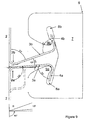
- In an embodiment the free ends of the upstanding flanges abut the securing notches of the recesses in the retaining elements head-on, i.e. the extremity of the free end touches the securing notch when a pulling force is exerted on the panel. Preferably, the recesses are slot- or slit-shaped as a result of the elongation of the securing notches. The advantage of the use of such a shaped recess is that the demand on tolerance of the length of the free edge may be slightly relaxed because the end of the free end generally does not touch the far end of the recess. The distance between the end of the free end and the far end of the recess is the length tolerance that the panel can endure. The dashed extension of the free ends in
figure 9 illustrates this clearly. In this embodiment the inside edge or the bend between the upstanding flange and the free end of the upstanding flange abut the securing notch when a pulling force is exerted on the panel. These touching points are indicated with the asterisk (*) infigure 9 . - The panels may comprise a perforated or mesh portion in the intermediate portion. Although the intermediate portion is preferably flat to produce a smooth façade, it is also possible to provide the intermediate portion with beads, stiffening ribs, micro lines or ridges. This may have a technical reason, e.g. to increase stiffness of the panel, or an aesthetical reason.
- In an embodiment of the invention the angle between one of the upstanding flanges and the intermediate portion of the panels is smaller than 90°. When the panels are mounted on a vertical or tilted surface (i.e. non-horizontal), the panels are mounted such that the angle between the bottom flange and the intermediate portion is the acute angle, and the angle between the top flange and the intermediate portion is the obtuse angle. In an embodiment of the invention the angle between one of the upstanding flanges and the intermediate portion of the panels is larger than 90°. In an embodiment of the invention the angle between one of the upstanding flanges and the intermediate portion of the panels is smaller than 90° and the angle between the other upstanding flange and the intermediate portion of the panel is larger than 90°.
- In an embodiment of the invention, one, more or all of the
retaining element 5 comprise twoupstanding flanges recesses panel 1, and which recesses 8a,8b are provided with securingnotches - This embodiment allows an even more secure mounting of the panel into the retaining element by using both upstanding flanges of the retaining element to hold the upstanding flange of one panel, or it allows two neighbouring panels to be mounted, one using the one upstanding flange of the retaining element, and the neighbouring panel in the other upstanding flange.
- In an embodiment of the invention the
upstanding flanges intermediate portion 2 when the panel is seen in cross section along a line perpendicular to theedges upstanding flange 3a is (180-(alpha + beta))°. - In this embodiment, the tilted upstanding flanges result in a tilted gap between two adjoining panels, particularly when mounted vertically, which prevents our counteracts water to seep through the gap towards the building or the support structure. The angle between the two adjoining flanges, β, is 0 in this case. When the panels are mounted in a more or less vertical position, the angle a is sharp, i.e. less than 90° to avoid water permeating through the gap between two adjoining upstanding flanges of two adjoining panels. Although in the absence of a sealant between the two adjoining panels there will always be some capillary effect, this will not result in water penetrating the façade, particularly not when β is not zero, because the capillary effect is reduced when the distance between the two upstanding flanges increases. A positive β result in an increasing distance (see
figure 4 ). - However, it will be clear that this embodiment will also comprise panels wherein β is not 0. This results in the upstanding flanges of adjoining panels not to be precisely parallel leading to a gap between upstanding flanges of the two panels not to be equidistant (see
figure 4 ) but the gap is wider near the building structure. This widening gap effectively counteracts the capillary effect that such a gap may have, and penetration of moisture through the gap is reduced or prevented. The preferably downward sloping of the gap as illustrated infigure 3 counteracts penetration of moisture as well as the penetration of wind driven rain. Since the sharp angle between theintermediate portion intermediate portion - The inventors found that it may even be beneficial to use panels wherein β is larger than 5° because it allows quick and precise mounting of the panels. It was found that β is preferably larger than 5°. It is preferable that the angle is not larger than 25°. In a preferred embodiment the angle is between 10 and 20°, e.g. 15°.
- In an embodiment of the invention the panels are made from sheet material of steel, a steel alloy, aluminium or an aluminium alloy, preferably by roll-forming, and wherein the panels are optionally coated with coating layers providing the panels with corrosion protection and/or colour and/or texture. A suitable thickness of the panels is between 0.5 and 2.5 mm, e.g. about 1 mm.
- Since the shape of the panel is relatively simple, it can be produced cheaply. The panels may be produced by simple bending or press-braking, but preferably by roll-forming. By using a dedicated roll-former, the panels can be produced on the erection site of a building. Such a dedicated roll-former may be transported to the erection site in a standard transport- or sea-container
- In an embodiment of the invention a plurality of panel retaining elements is mounted onto the building and adjoining panels are snapped into the
recesses upstanding flange 3a of a first panel and theupstanding flange 3b of a second panel longitudinally adjoin so as to allow mounting the adjoining panels to the building by snapping the adjoining v- or u-shaped flanges of the panels into the correspondingrecesses upstanding flanges 7 of one ormore retaining elements 5. Longitudinal adjoining means that theedge 2a of one panel adjoins theedge 2b of the adjoining panel. - The panel retaining elements may be mounted to the building individually as single brackets, or as a part of a rail comprising a plurality of brackets over the length of the rail. The plurality of brackets over the length of the rail may be individually premounted single brackets, or the rail may be provided with recesses to receive and hold the upstanding flanges of the panels (
item 5 inFigure 11a ). In a further embodiment, the single brackets or the rail comprising the plurality of brackets are mounted to the building using a further U-shaped bracket (item 13 inFigure 11 ) which allow for some translational tolerance during mounting of the rails or brackets to the building, thereby facilitating alignment of the rails or brackets, preferably wherein the legs of the U-shaped bracket are provided with notches which allow the U-shaped bracket to take up some rotational tolerance during mounting of the rails or brackets to the building. - In this embodiment, the gap between two adjoining panels is identical over the entire length of the two adjoining panels, thereby achieving a nice (i.e. aesthetically pleasing) finish of the façade. By using panels with a recess in the upstanding flange, the recess is identical over the entire length of the two adjoining panel. The presence of such a gap allows for thermal expansion of the panel without the risk of buckling the flat part of the panel. It also allows for ventilation and a degree of pressure equalisation between the front and back sides of the panel when subjected to dynamic wind loads, and thereby reduces wind-suction effects.
- In an embodiment of the invention a plurality of panel retaining elements is mounted onto the building and wherein the
upstanding flanges recesses upstanding flanges recesses edge 2d of the intermediate portion of the neighbouring panel. - In this embodiment, there is no gap between two neighbouring panels, thereby achieving a smooth finish of the façade.
- In an embodiment of the invention, an intermediate material is provided between the upstanding flanges and the panel retaining element when mounted. This intermediate material may prevents the occurrence of rattling as a result of metal-metal contact, for instance in windy circumstances. This intermediate material may be in the form of a layer or material, or a loose inlay which e.g. is put in place in the recesses of the clip prior to clicking the panel in place, or an inlay which is clipped into or onto the recesses of the clip prior to clicking the panel in place. The material may be a polymer material, such as a plastic or a rubber-like material. The intermediate material may also be used to improve an reduced friction of the panels during mounting, or to correct minor size deviations (tolerance). By using different materials at different retaining elements, some panel retaining elements could be used as fixed points (by using high friction material) whereas other retaining elements could allow some movement to allow the thermal expansion of the panels (by using very low friction material). The intermediate material may also be provided with beards or spring elements so as to allow easy insertion of the panel in one direction during mounting the panel and difficult extraction in the opposite direction, thereby adding to the gripping power of the retaining element on the flanges of the panel when a pulling force is exerted on the panel.
- In an embodiment of the invention the panels may also be provided with an upstanding flange at one or both of the edges 2c and/or 2d. This upstanding flange may serve to create an aesthetic or safety enhancing effect when the panel is mounted as the last panel near the edge of the façade. This upstanding flange would preferably be bent in the same direction as the upstanding flanges which are clipped into the panel retaining elements. It is preferable that this upstanding flange is provided to the panel on the building site. This has the advantage that the width of the panel can be fine-tuned on site by cutting the panel to the correct width followed by bending the edge. To enable a nice finish of the panel, the corners of the panel need to be cut out prior to bending the flange to avoid creases in the panel.
- It should be noted that the modular system according to the invention would also be suitable for producing a roof structure. However, as the roof would not be impermeable to water at the locations where the panels abut, it is used as an over-cladding, e.g. over a standing seam roof which is waterproof, where the standing seams can be used to fix the panel retaining elements to. Additional precautions to make the roof impermeable to water at the location of the where panels adjoining by sealing the gaps between adjoining and/or neighbouring panels e.g. by using a sealant, or waterproof inlays or rubberlike profiles have proven not to provide a long term waterproofing. Use of the modular system for producing a ceiling structure (i.e. indoors) is also possible. The combination of such a ceiling, for instance with perforated or mesh intermediate portions in the panels, with sound-proofing material behind the intermediate portion provides an acoustic ceiling. Heating or cooling elements may also be mounted behind the perforated panels.
- According to a second aspect of the invention a method of assembling a façade structure on a building using a plurality of panels I members and panel retaining elements 5 for mounting the panels to the building is provided wherein said panels 1 comprise an intermediate portion 2 extending between two upstanding flanges 3a,3b located on opposite edges 2a,2b of the intermediate portion 2 and wherein the free ends 4a,4b of the upstanding flanges 3a,3b are bent so as to extend towards the back side 2f of the intermediate portion of the panel 1 thereby forming substantially v- or u-shaped flanges and wherein the free ends 4a,4b of the bent upstanding flanged do not touch the back side 2f of the intermediate portion 2, and wherein said panel retaining elements 5 comprise a base portion 6 for securing the retaining element to the building and at least one upstanding flange 7, wherein the upstanding flange 7 is provided with recesses 8a,8b which have a substantially complementary shape to the shape of the substantially v- or u-shaped flanges of the panels, and which recesses are provided with securing notches 9a,9b the method comprising the step of mounting subsequent panels to the building structure by snapping the v- or u-shaped flanges of the panels into the corresponding recesses 8a,8b in the upstanding flanges 7 of one or more retaining elements 5, and wherein the securing notches 9a,9b secure the panels in place.
- The mounting of the panels preferably occurs by hanging the upper upstanding flange part of a panel in the
recesses 8b, allowing it to hang onto the securingnotch 9b, and then clicking the lower upstanding flange into therecess 8a, allowing it to be secured by the securingnotch 9a. Alternatively, but less preferably, the panels may be mounted by pressing the two upstanding flanges into the recesses and behind securing notches simultaneously. - Since these panels do not rely on the male-female interlocking system, there is no prescribed order of mounting the panels. The mounting may start at the bottom of the façade and move upwards, or start at the top of the façade and move downwards, or the mounting may start at any chosen place of the building and move upwards and downwards. It is even possible to leave out panels during construction, only to fill the gaps later. This may be extremely helpful when during building a scaffolding is used. For safety reasons, such a scaffolding needs to be secured to the building. By securing the scaffolding to the building at the locations where the panels are not yet mounted the securing points can later be covered by a panel when the scaffolding is removed. The clicking into place and the self-securing behind the securing notches of the panel retaining elements means that the panels can be very easily and quickly mounted by a simple pressing and snapping into place, even in between panels already mounted. The deformation of the upstanding flanges during mounting is preferably an elastic deformation only. The fact that the order of mounting the panels is irrelevant is also important when mounting coloured panels. Minimal differences in colour or texture of subsequent batches of material from which the panels are produced, e.g. by roll forming, become visible when consecutively mounting all panels of one coil and then all panels of another batch. The method according to the invention allows mounting the panels scattered over the façade and filling the gaps scattered with the panels of any following bath. The scattering eliminates any differences in texture or colour.
- In an embodiment of the invention the method involves using one, more or all retaining elements wherein the retaining elements comprise two
upstanding flanges recesses panel 1, and which recesses 8a, 8b are provided with securingnotches - In an embodiment of the invention, the method of assembling a façade involves mounting consecutive panels in such a manner that the gap between the two neighbouring panels is minimised by abutting the edge 2c of the intermediate portion of the first panel against the
edge 2d of the intermediate portion of the neighbouring panel. In this embodiment, there is no gap between two neighbouring panels, thereby achieving a smooth finish of the façade. - In an embodiment of the invention the method uses panels with upstanding flanges of the panels which are not perpendicular to the intermediate portion when the panel is seen in cross section along a line perpendicular to the edges, but wherein the angle formed by the intermediate portion and the first upstanding flange is α°, and the angle formed by the intermediate portion and the second upstanding flange is (180 - (alpha + beta))°. In this embodiment, the tilted upstanding flanges result in a tilted gap between two adjoining panels, particularly when mounted vertically, which prevents our counteracts water to seep through the gap towards the building or the support structure. Another advantage of using the tilted flanges is that the panels can not be inadvertently mounted upside down. Particularly when using coloured or textured panels this avoids apparent colour differences because all panels are mounted in the same direction.
- In an embodiment of the invention a method of repairing the façade structure is provided comprising the steps of removing the damaged panel or damaged panels individually, for instance by cutting the member so as to enable removal of the panel without damaging the panel retaining elements holding the damaged panel, followed by replacing the removed panel by snapping a replacement panel in place. Due to the absence of the male-female interlocking, only the damaged panels need to be removed. By removing the damaged panel(s) without damage to the retaining elements, replacement panel of the correct size can be easily and quickly snapped in place. This repair option is very important in locations where damage to the panel can occur for instance by accidents or vandalism such as scratching, graffiti or even shooting using firearms.
- The invention will now be further described by way of non-limiting examples and with reference to the accompanying drawings in which:
-
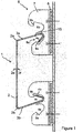
Figure 1 shows a schematic drawing of a panel clamped into the panel retaining elements. Thepanel 1 is not to scale. The height of theupstanding flanges opposite edges intermediate portion 2 is exaggerated in respect to the size of the intermediate portion. In practice, the retainingelements 5 are mounted at a larger distance from each other. The free ends 4a,4b of theupstanding flanges panel retaining elements 5 comprise abase portion 6 for securing the retaining element to the building and at least oneupstanding flange 7, which is provided withrecesses notches recesses -
Figure 2 shows a drawing of a part of a façade mounted on a support structure. The three panels adjoin, showing a nice even gap to the observer, and a smooth finish of the façade. Thepanel retaining elements 5 are mounted ontosupport structure 10. -
Figure 3 shows a schematic drawing of two adjoining panels mounted in one panel retaining element. The reference numerals are as explained hereinabove.Figure 4 shows a photographic representation of two adjoining panels mounted in one panel retaining element as schematically shown inFigure 3 . It is clearly visible that the gap between the two adjoiningupstanding flanges intermediate portion intermediate portion Figure 4 . -
Figure 5 shows a schematic drawing of two adjoining panels without a gap in the façade (a), and with a gap running over the façade (b). InFigure 5a the panels are used resulting in the façade ofFigure 2 . When the panel ofFigure 5b is used, a wider gap is visible in the façade. This may have a desired esthetical or functional effect. -
Figure 6 shows a schematic drawing of the effect of a pulling force, for instance by wind suction, on the intermediate portion of a panel. The pulling force makes thefree edge -
Figure 7 a to c shows a sequence of events when replacing damaged panels from a completed façade. By longitudinally cutting the damaged panels, the panels can be removed without damaging the panel retaining elements. New panels can be easily inserted between the undamaged panels. -
Figure 8 shows an example of aloose inlay 11 as an intermediate material which is made by injection moulding and which is clipped to the recesses in thepanel retaining elements 5. The beards orspring elements 12 to retain thefree edges upstanding flanges flanges 7 of thepanel retaining element 5. -
Figure 9 shows a cross-section of an arrangement according to the invention where the flanged edges of two adjoining panels are slotted in the slot-shaped recessed of the retaining element. The slot-shaped recesses are the result of the elongation of the securingnotches figure 1 . Also the hill partly defining the recesses infigure 1 is absent, because it has no function in this preferable embodiment. By means of non-limiting example some angles at the flanges are indicated. The angle for β is 15°. The flanged edge of the bottom panel abuts the securingnotch 9a at the location of the bend of the free end of the flanged edge, whereas the flanged edge of the top panel abuts the securingnotch 9b with the inner side of the free end of the flanged edge. The touching points are indicated with an asterisk (*). This embodiment is particularly well suited for the mounting by hanging the upper upstanding flange and clicking the lower upstanding flange. This Fix-Click mechanism is preferable over the simulatenous snapping or clicking into place of the upper and lower upstanding flanges. -
Figure 10 panels for standing seam roofs with a tapered intermediate portion, an X-shaped intermediate portion, a concave intermediate portion, a convex intermediate portion or combination thereof. These drawings are included to explain the various shapes involved. According to the invention, panels of similar shapes can be used in the modular system according to the invention, wherein the standing seam parts infigure 10 are replaced by upstanding flanges in accordance with this invention. -
Figure 11 shows a bracket comprising theloose inlays 11 when clipped tinto the recesses in theupstanding flanges 7 of thepanel retaining element 5. Theright inlay 11 is provided with an upper panel clicked into the recess 8 and securing notch 9 and an adjoining lower panel hanged into the recess 8 and securing notch 9. The panel retaining 5 is mounted to the building through aU-shaped bracket 13 by means of a securingelement 14 such as a nut-and-bolt, a screw, a blind rivet, or an equivalent, using washers if needed, through a slit-shaped opening in the legs of the U-shaped bracket. In this example the slit-shaped opening is provided in an inwardly directed notch in the leg. This notch allows some rotational tolerance as the rail can be rotated slightly and still be secured in the bracket.
Claims (13)
- A modular system for a façade structure for a building comprising panels (1) and panel retaining elements (5) for mounting the panels to the building, wherein said panels (1) comprise an intermediate portion (2) extending between two upstanding flanges (3a,3b) located on opposite edges (2a,2b) of the intermediate portion (2) and wherein the free ends (4a,4b) of the upstanding flanges (3a,3b) are bent so as to extend towards the back side (2f) of the intermediate portion (2) of the panel (1) thereby forming substantially v- or u-shaped flanges and wherein the free ends (4a,4b) of the bent upstanding flanged do not touch the back side (2f) of the intermediate portion (2), and wherein said panel retaining elements (5) comprise a base portion (6) for securing the retaining element to the building and at least one upstanding flange (7), wherein the upstanding flange (7) is provided with recesses (8a,8b) and which recesses are provided with securing notches (9a,9b) so as to allow mounting the panels to the building structure by snapping the free ends (4a, 4b) of the v- or u-shaped flanges of the panels into the corresponding recesses (8a,8b) in the upstanding flanges (7) of one or more retaining elements (5), and wherein the securing notches (9a,9b) secure the panels in place without the use of a male-female connection between subsequent panels (1), wherein the angle between one of the upstanding flanges and the intermediate portion of the panels is smaller than 90° and the angle between the other upstanding flange and the intermediate portion of the panel is larger than 90° and wherein the panels are made from sheet material of steel, a steel alloy, aluminium or an aluminium alloy by roll-forming.
- Modular system according to claim 1, wherein one, more or all of the retaining element (5) comprise two upstanding flanges (7a,7b), wherein both upstanding flanges are provided with recesses (8a,8b), and which recesses (8a,8b) are provided with securing notches (9a,9b).
- Modular system according to any one of the preceding claims wherein the upstanding flanges (3a,3b) of the panels are not perpendicular to the intermediate portion (2) when the panel is seen in cross section along a line perpendicular to the edges (2a,2b), but wherein the angle formed by the intermediate portion and the first upstanding flange (3b) is α°, and the angle formed by the intermediate portion and the second upstanding flange (3a) is (180-(α+β))°, wherein β is the angle between the understanding flanges (3a,3b), and wherein β is from O to not larger than 25°.
- Modular system according to any one of the preceding claims wherein the panels are optionally coated with coating layers providing the panels with corrosion protection and/or colour and/or texture.
- Modular system according to claim 3 or 4 wherein the angle β between the upstanding flanges (3a,3b) is O.
- Modular system according to any one of claim 3 to 5 wherein the angle β between the upstanding flanges (3a,3b) is at least 5°.
- Modular system according to any one of the preceding claims wherein the recesses (8a,8b) are slot- or slit-shaped to receive the free ends (4a, 4b) of the upstanding flanges (3a, 3b) of the panels (1), or wherein the recesses (8a, 8b) have a shape which is substantially complementary to the shape of the substantially v- or u-shaped flanges (3a, 3b, 4a, 4b).
- Modular system according to any one of the preceding claims wherein an intermediate material is provided between the upstanding flanges and the panel retaining element.
- Modular system according to claim 8 wherein the intermediate material is provided in the form of a loose inlay.
- Façade comprising the modular system according to any one of the preceding claims, wherein a plurality of panel retaining elements is mounted onto the building and wherein adjoining panels are snapped into the recesses (8a,8b) of the retaining elements and wherein the upstanding flange (3a) of a first panel and the upstanding flange (3b) of a second panel longitudinally adjoin so as to allow mounting the adjoining panels to the building by snapping the adjoining flanges of the panels into the recesses (8a,8b) in the upstanding flanges (7) of one or more retaining elements (5).
- Method of assembling a façade structure on a building using a plurality of panels (1) members and panel retaining elements (5) for mounting the panels to the building wherein said panels (1) comprise an intermediate portion (2) extending between two upstanding flanges (3a,3b) located on opposite edges (2a,2b) of the intermediate portion (2) and wherein the free ends (4a,4b) of the upstanding flanges (3a,3b) are bent so as to extend towards the back side (2f) of the intermediate portion (2) of the panel (1) thereby forming substantially v- or u-shaped flanges and wherein the free ends (4a,4b) of the bent upstanding flanged do not touch the back side (2f) of the intermediate portion (2), and wherein said panel retaining elements (5) comprise a base portion (6) for securing the retaining element to the building and at least one upstanding flange (7), wherein the upstanding flange (7) is provided with recesses (8a,8b), and which recesses are provided with securing notches (9a,9b), the method comprising the step of mounting subsequent panels to the building structure by snapping the free ends (4a, 4b) of the v- or u-shaped flanges of the panels into the corresponding recesses (8a,8b) in the upstanding flanges (7) of one or more retaining elements (5), and wherein the securing notches (9a,9b) secure the panels in place, without the use of a male-female connection between subsequent panels (1), wherein the angle between one of the upstanding flanges and the intermediate portion of the panels is smaller than 90° and the angle between the other upstanding flange and the intermediate portion of the panel is larger than 90° and wherein the panels are made from sheet material of steel, a steel alloy, aluminium or an aluminium alloy by roll-forming.
- Method of assembling a façade structure on a building according to claim 11 wherein the consecutive panels are mounted in such a manner that the gap between the two neighbouring panels is minimised by abutting the edge (2c) of the intermediate portion of the first panel against the edge (2d) of the intermediate portion of the neighbouring panel, or wherein the consecutive panels are mounted in such a manner that the visible gap between the edges of the two neighbouring panels (2c, 2d) at the location where the panels adjoin is equidistant.
- Method of repairing the façade structure produced in accordance with claim 11 or 12 by removing the damaged panel, for instance by cutting the member so as to enable removal of the panel, without damaging the panel retaining elements holding the damaged panel, followed by replacing the removed panel by snapping a replacement panel in place.
Priority Applications (2)
| Application Number | Priority Date | Filing Date | Title |
|---|---|---|---|
| PL09776872T PL2304123T3 (en) | 2008-07-16 | 2009-06-29 | A modular system for a facade structure |
| EP09776872.5A EP2304123B1 (en) | 2008-07-16 | 2009-06-29 | A modular system for a facade structure |
Applications Claiming Priority (4)
| Application Number | Priority Date | Filing Date | Title |
|---|---|---|---|
| EP08012840 | 2008-07-16 | ||
| US8154008P | 2008-07-17 | 2008-07-17 | |
| EP09776872.5A EP2304123B1 (en) | 2008-07-16 | 2009-06-29 | A modular system for a facade structure |
| PCT/EP2009/004677 WO2010006691A1 (en) | 2008-07-16 | 2009-06-29 | A modular system for a facade structure |
Publications (2)
| Publication Number | Publication Date |
|---|---|
| EP2304123A1 EP2304123A1 (en) | 2011-04-06 |
| EP2304123B1 true EP2304123B1 (en) | 2013-08-07 |
Family
ID=39951493
Family Applications (1)
| Application Number | Title | Priority Date | Filing Date |
|---|---|---|---|
| EP09776872.5A Active EP2304123B1 (en) | 2008-07-16 | 2009-06-29 | A modular system for a facade structure |
Country Status (7)
| Country | Link |
|---|---|
| US (1) | US8464487B2 (en) |
| EP (1) | EP2304123B1 (en) |
| CA (1) | CA2730833C (en) |
| ES (1) | ES2431942T3 (en) |
| PL (1) | PL2304123T3 (en) |
| RU (1) | RU2495207C2 (en) |
| WO (1) | WO2010006691A1 (en) |
Families Citing this family (16)
| Publication number | Priority date | Publication date | Assignee | Title |
|---|---|---|---|---|
| US9151052B2 (en) * | 2011-01-04 | 2015-10-06 | Advanced Architectural Products, Llc | Insulation system for buildings |
| US8826620B2 (en) * | 2011-01-04 | 2014-09-09 | Advanced Architectural Products, Llc | Polymer-based bracket system for metal panels |
| US8833025B2 (en) * | 2011-01-04 | 2014-09-16 | Advanced Architectural Products, Llc | Polymer-based bracket system for exterior cladding |
| US10113317B1 (en) * | 2015-04-16 | 2018-10-30 | Gordon Sales, Inc. | Apparatus and method for hanging architectural panels with concealed attachment points |
| WO2017210363A1 (en) | 2016-05-31 | 2017-12-07 | Advanced Architectural Products, Llc | Insulating structure for buildings |
| US10443229B2 (en) | 2016-06-09 | 2019-10-15 | Advanced Architectural Products, Llc | Insulation system for buildings |
| KR101937711B1 (en) * | 2017-12-22 | 2019-01-11 | 주식회사 유토플러스 | System for dry execution of finishing material |
| CA3123886A1 (en) | 2019-01-17 | 2020-07-23 | James DAHLMAN | Drug delivery systems containing oxidized cholesterols |
| GB2581176B (en) * | 2019-02-06 | 2022-08-03 | Mydek Ltd | Construction panel system |
| GB2581177B (en) * | 2019-02-06 | 2022-06-08 | Mydek Ltd | Construction panel system |
| CN110905107B (en) * | 2019-11-19 | 2021-04-09 | 上海宝冶集团有限公司 | Curved curtain wall keel construction method |
| US11542702B2 (en) | 2020-06-25 | 2023-01-03 | Advanced Architectural Products, Llc | Adjustable support system for a building structure and a wall structure having an adjustable support system |
| US11566421B2 (en) | 2020-06-25 | 2023-01-31 | Advanced Architectural Products, Llc | Adjustable support system for a building structure and a wall structure having an adjustable support system |
| EP4219859A1 (en) * | 2022-01-26 | 2023-08-02 | David Atias | Customizable cladding system |
| CN114718269B (en) * | 2022-04-02 | 2023-09-08 | 中能建路桥工程有限公司 | Building insulation board positioning and mounting device |
| US12031327B1 (en) | 2022-08-29 | 2024-07-09 | Gordon Sales, Inc. | Suspended ceiling grid hanging system |
Citations (1)
| Publication number | Priority date | Publication date | Assignee | Title |
|---|---|---|---|---|
| EP1914360A1 (en) * | 2006-10-20 | 2008-04-23 | Corus Bausysteme GmbH | Assembly of two building members, a retaining element and a covering element and use thereof |
Family Cites Families (11)
| Publication number | Priority date | Publication date | Assignee | Title |
|---|---|---|---|---|
| US2607971A (en) * | 1947-02-05 | 1952-08-26 | United Carr Fastener Corp | Panel fastener device |
| NL6502317A (en) | 1965-02-24 | 1966-08-25 | ||
| DE1929732U (en) | 1965-10-12 | 1965-12-23 | Manfred Schierling | FACADE CLADDING KIT. |
| DE1970725U (en) * | 1967-03-08 | 1967-10-19 | Hunter Douglas Rotterdam | COMPONENT SET FOR CEILING CLADDING, IN PARTICULAR A HANGED CEILING. |
| BE900278R (en) | 1984-08-01 | 1985-02-01 | Hunter Douglas Ind Bv | Wall or ceiling panel fixing clip - has position for holding two adjoining panels and positions either side to hold two single panels |
| CN1068087C (en) * | 1992-11-06 | 2001-07-04 | 东陶机器株式会社 | Mechanism for connecting of decorating plates |
| WO2000023672A1 (en) | 1998-10-16 | 2000-04-27 | Smith, Lachlan, Kerry, Oliver | Screwless covering system |
| DE10106752A1 (en) * | 2001-02-14 | 2002-08-29 | Km Europa Metal Ag | cladding |
| RU2241102C1 (en) * | 2004-01-14 | 2004-11-27 | Морозов Геннадий Яковлевич | Method and device for vented facade mounting without marks and conducting unit for assembling and feeding multi-layered heat insulation for wall enclosure forming |
| KR200348691Y1 (en) * | 2004-02-04 | 2004-05-03 | 주식회사 삼우이엠씨 | Facing panels for buildings |
| US8336843B2 (en) * | 2009-07-16 | 2012-12-25 | Usg Interiors, Llc | Secure locking attachment device useful with suspended ceiling systems |
-
2009
- 2009-06-29 PL PL09776872T patent/PL2304123T3/en unknown
- 2009-06-29 ES ES09776872T patent/ES2431942T3/en active Active
- 2009-06-29 CA CA2730833A patent/CA2730833C/en active Active
- 2009-06-29 US US13/003,876 patent/US8464487B2/en active Active
- 2009-06-29 EP EP09776872.5A patent/EP2304123B1/en active Active
- 2009-06-29 RU RU2011105623/03A patent/RU2495207C2/en active
- 2009-06-29 WO PCT/EP2009/004677 patent/WO2010006691A1/en not_active Ceased
Patent Citations (1)
| Publication number | Priority date | Publication date | Assignee | Title |
|---|---|---|---|---|
| EP1914360A1 (en) * | 2006-10-20 | 2008-04-23 | Corus Bausysteme GmbH | Assembly of two building members, a retaining element and a covering element and use thereof |
Also Published As
| Publication number | Publication date |
|---|---|
| CA2730833A1 (en) | 2010-01-21 |
| RU2011105623A (en) | 2012-08-27 |
| US20110146182A1 (en) | 2011-06-23 |
| RU2495207C2 (en) | 2013-10-10 |
| US8464487B2 (en) | 2013-06-18 |
| CA2730833C (en) | 2013-01-08 |
| WO2010006691A1 (en) | 2010-01-21 |
| EP2304123A1 (en) | 2011-04-06 |
| ES2431942T3 (en) | 2013-11-28 |
| PL2304123T3 (en) | 2014-01-31 |
| HK1156088A1 (en) | 2012-06-01 |
Similar Documents
| Publication | Publication Date | Title |
|---|---|---|
| CA2730833C (en) | A modular system for a facade structure | |
| US9297166B2 (en) | Fixing system for cladding and a cladded structure | |
| US3903670A (en) | Apparatus and method for hanging siding members on supporting surfaces | |
| US20180171640A1 (en) | Rail system | |
| CA2661114A1 (en) | Wall panel system with hook-on clip | |
| EP3728759B1 (en) | A facade unit mounting apparatus | |
| CA2773260C (en) | Mounting clip and wall panel assembly as well as kit and method | |
| RU2663519C1 (en) | Flexible suspension universal decorative suspension framework ceiling system | |
| NO20161528A1 (en) | Method for mounting panels of the insulating layer to the building wall and a set of elements for mounting panels of the insulating layer to the building wall | |
| HK1156088B (en) | A modular system for a facade structure | |
| WO2015067276A1 (en) | Facade mounting system | |
| WO2005071180A1 (en) | Holding assembly for holding a building sheet | |
| US6305144B1 (en) | Window frame and method | |
| RU222696U1 (en) | Horizontal mounting profile for fastening façade system cladding with hidden fastening of facing tiles | |
| US20200173174A1 (en) | Façade System | |
| EP4506521A1 (en) | System for obtaining a dry or mechanical building envelope or a cladding of building walls as well as building with cladded wall and method therefore | |
| WO2019212393A1 (en) | Stretch mounted ventilated facade system and method for installing same | |
| CN211287328U (en) | Door plate with metal strip embedded in front surface | |
| RU2649199C1 (en) | Wall cladding system | |
| CN209874328U (en) | Fastener for heat-insulating and decorating integrated wallboard | |
| JP2026060261A (en) | Horizontal roofing exterior structure and its construction method | |
| RU2368743C1 (en) | Facing | |
| WO2011054023A1 (en) | Building panel | |
| JP3984854B2 (en) | Renovation structure and method of side roof | |
| UA120104C2 (en) | Method and assembly for cladding or covering buildings |
Legal Events
| Date | Code | Title | Description |
|---|---|---|---|
| PUAI | Public reference made under article 153(3) epc to a published international application that has entered the european phase |
Free format text: ORIGINAL CODE: 0009012 |
|
| 17P | Request for examination filed |
Effective date: 20110216 |
|
| AK | Designated contracting states |
Kind code of ref document: A1 Designated state(s): AT BE BG CH CY CZ DE DK EE ES FI FR GB GR HR HU IE IS IT LI LT LU LV MC MK MT NL NO PL PT RO SE SI SK TR |
|
| AX | Request for extension of the european patent |
Extension state: AL BA RS |
|
| RAX | Requested extension states of the european patent have changed |
Extension state: BA Payment date: 20110216 |
|
| REG | Reference to a national code |
Ref country code: HK Ref legal event code: DE Ref document number: 1156088 Country of ref document: HK |
|
| GRAP | Despatch of communication of intention to grant a patent |
Free format text: ORIGINAL CODE: EPIDOSNIGR1 |
|
| RIC1 | Information provided on ipc code assigned before grant |
Ipc: E04D 3/30 20060101AFI20120612BHEP Ipc: E04D 3/363 20060101ALI20120612BHEP Ipc: E04F 13/12 20060101ALI20120612BHEP Ipc: E04F 13/08 20060101ALI20120612BHEP |
|
| GRAJ | Information related to disapproval of communication of intention to grant by the applicant or resumption of examination proceedings by the epo deleted |
Free format text: ORIGINAL CODE: EPIDOSDIGR1 |
|
| GRAP | Despatch of communication of intention to grant a patent |
Free format text: ORIGINAL CODE: EPIDOSNIGR1 |
|
| INTG | Intention to grant announced |
Effective date: 20130425 |
|
| GRAS | Grant fee paid |
Free format text: ORIGINAL CODE: EPIDOSNIGR3 |
|
| RIN1 | Information on inventor provided before grant (corrected) |
Inventor name: KENDA, MARIO Inventor name: NEUWALD, JUERGEN Inventor name: SCHMITT, HORST |
|
| GRAA | (expected) grant |
Free format text: ORIGINAL CODE: 0009210 |
|
| AK | Designated contracting states |
Kind code of ref document: B1 Designated state(s): AT BE BG CH CY CZ DE DK EE ES FI FR GB GR HR HU IE IS IT LI LT LU LV MC MK MT NL NO PL PT RO SE SI SK TR |
|
| AX | Request for extension of the european patent |
Extension state: BA |
|
| REG | Reference to a national code |
Ref country code: GB Ref legal event code: FG4D |
|
| REG | Reference to a national code |
Ref country code: CH Ref legal event code: EP Ref country code: AT Ref legal event code: REF Ref document number: 625851 Country of ref document: AT Kind code of ref document: T Effective date: 20130815 |
|
| REG | Reference to a national code |
Ref country code: IE Ref legal event code: FG4D |
|
| REG | Reference to a national code |
Ref country code: DE Ref legal event code: R096 Ref document number: 602009017850 Country of ref document: DE Effective date: 20131002 |
|
| REG | Reference to a national code |
Ref country code: NL Ref legal event code: T3 |
|
| REG | Reference to a national code |
Ref country code: HK Ref legal event code: GR Ref document number: 1156088 Country of ref document: HK |
|
| REG | Reference to a national code |
Ref country code: LT Ref legal event code: MG4D |
|
| PG25 | Lapsed in a contracting state [announced via postgrant information from national office to epo] |
Ref country code: PT Free format text: LAPSE BECAUSE OF FAILURE TO SUBMIT A TRANSLATION OF THE DESCRIPTION OR TO PAY THE FEE WITHIN THE PRESCRIBED TIME-LIMIT Effective date: 20131209 Ref country code: IS Free format text: LAPSE BECAUSE OF FAILURE TO SUBMIT A TRANSLATION OF THE DESCRIPTION OR TO PAY THE FEE WITHIN THE PRESCRIBED TIME-LIMIT Effective date: 20131207 Ref country code: SE Free format text: LAPSE BECAUSE OF FAILURE TO SUBMIT A TRANSLATION OF THE DESCRIPTION OR TO PAY THE FEE WITHIN THE PRESCRIBED TIME-LIMIT Effective date: 20130807 Ref country code: LT Free format text: LAPSE BECAUSE OF FAILURE TO SUBMIT A TRANSLATION OF THE DESCRIPTION OR TO PAY THE FEE WITHIN THE PRESCRIBED TIME-LIMIT Effective date: 20130807 Ref country code: NO Free format text: LAPSE BECAUSE OF FAILURE TO SUBMIT A TRANSLATION OF THE DESCRIPTION OR TO PAY THE FEE WITHIN THE PRESCRIBED TIME-LIMIT Effective date: 20131107 Ref country code: HR Free format text: LAPSE BECAUSE OF FAILURE TO SUBMIT A TRANSLATION OF THE DESCRIPTION OR TO PAY THE FEE WITHIN THE PRESCRIBED TIME-LIMIT Effective date: 20130807 Ref country code: CY Free format text: LAPSE BECAUSE OF FAILURE TO SUBMIT A TRANSLATION OF THE DESCRIPTION OR TO PAY THE FEE WITHIN THE PRESCRIBED TIME-LIMIT Effective date: 20130710 |
|
| REG | Reference to a national code |
Ref country code: PL Ref legal event code: T3 |
|
| PG25 | Lapsed in a contracting state [announced via postgrant information from national office to epo] |
Ref country code: FI Free format text: LAPSE BECAUSE OF FAILURE TO SUBMIT A TRANSLATION OF THE DESCRIPTION OR TO PAY THE FEE WITHIN THE PRESCRIBED TIME-LIMIT Effective date: 20130807 Ref country code: LV Free format text: LAPSE BECAUSE OF FAILURE TO SUBMIT A TRANSLATION OF THE DESCRIPTION OR TO PAY THE FEE WITHIN THE PRESCRIBED TIME-LIMIT Effective date: 20130807 Ref country code: GR Free format text: LAPSE BECAUSE OF FAILURE TO SUBMIT A TRANSLATION OF THE DESCRIPTION OR TO PAY THE FEE WITHIN THE PRESCRIBED TIME-LIMIT Effective date: 20131108 Ref country code: SI Free format text: LAPSE BECAUSE OF FAILURE TO SUBMIT A TRANSLATION OF THE DESCRIPTION OR TO PAY THE FEE WITHIN THE PRESCRIBED TIME-LIMIT Effective date: 20130807 |
|
| PG25 | Lapsed in a contracting state [announced via postgrant information from national office to epo] |
Ref country code: CY Free format text: LAPSE BECAUSE OF FAILURE TO SUBMIT A TRANSLATION OF THE DESCRIPTION OR TO PAY THE FEE WITHIN THE PRESCRIBED TIME-LIMIT Effective date: 20130807 |
|
| PG25 | Lapsed in a contracting state [announced via postgrant information from national office to epo] |
Ref country code: EE Free format text: LAPSE BECAUSE OF FAILURE TO SUBMIT A TRANSLATION OF THE DESCRIPTION OR TO PAY THE FEE WITHIN THE PRESCRIBED TIME-LIMIT Effective date: 20130807 Ref country code: CZ Free format text: LAPSE BECAUSE OF FAILURE TO SUBMIT A TRANSLATION OF THE DESCRIPTION OR TO PAY THE FEE WITHIN THE PRESCRIBED TIME-LIMIT Effective date: 20130807 Ref country code: SK Free format text: LAPSE BECAUSE OF FAILURE TO SUBMIT A TRANSLATION OF THE DESCRIPTION OR TO PAY THE FEE WITHIN THE PRESCRIBED TIME-LIMIT Effective date: 20130807 Ref country code: RO Free format text: LAPSE BECAUSE OF FAILURE TO SUBMIT A TRANSLATION OF THE DESCRIPTION OR TO PAY THE FEE WITHIN THE PRESCRIBED TIME-LIMIT Effective date: 20130807 Ref country code: DK Free format text: LAPSE BECAUSE OF FAILURE TO SUBMIT A TRANSLATION OF THE DESCRIPTION OR TO PAY THE FEE WITHIN THE PRESCRIBED TIME-LIMIT Effective date: 20130807 |
|
| PLBE | No opposition filed within time limit |
Free format text: ORIGINAL CODE: 0009261 |
|
| STAA | Information on the status of an ep patent application or granted ep patent |
Free format text: STATUS: NO OPPOSITION FILED WITHIN TIME LIMIT |
|
| 26N | No opposition filed |
Effective date: 20140508 |
|
| REG | Reference to a national code |
Ref country code: DE Ref legal event code: R097 Ref document number: 602009017850 Country of ref document: DE Effective date: 20140508 |
|
| PG25 | Lapsed in a contracting state [announced via postgrant information from national office to epo] |
Ref country code: MC Free format text: LAPSE BECAUSE OF FAILURE TO SUBMIT A TRANSLATION OF THE DESCRIPTION OR TO PAY THE FEE WITHIN THE PRESCRIBED TIME-LIMIT Effective date: 20130807 Ref country code: LU Free format text: LAPSE BECAUSE OF FAILURE TO SUBMIT A TRANSLATION OF THE DESCRIPTION OR TO PAY THE FEE WITHIN THE PRESCRIBED TIME-LIMIT Effective date: 20140629 |
|
| REG | Reference to a national code |
Ref country code: IE Ref legal event code: MM4A |
|
| PG25 | Lapsed in a contracting state [announced via postgrant information from national office to epo] |
Ref country code: IE Free format text: LAPSE BECAUSE OF NON-PAYMENT OF DUE FEES Effective date: 20140629 |
|
| PG25 | Lapsed in a contracting state [announced via postgrant information from national office to epo] |
Ref country code: MT Free format text: LAPSE BECAUSE OF FAILURE TO SUBMIT A TRANSLATION OF THE DESCRIPTION OR TO PAY THE FEE WITHIN THE PRESCRIBED TIME-LIMIT Effective date: 20130807 |
|
| REG | Reference to a national code |
Ref country code: FR Ref legal event code: PLFP Year of fee payment: 8 |
|
| PG25 | Lapsed in a contracting state [announced via postgrant information from national office to epo] |
Ref country code: BG Free format text: LAPSE BECAUSE OF FAILURE TO SUBMIT A TRANSLATION OF THE DESCRIPTION OR TO PAY THE FEE WITHIN THE PRESCRIBED TIME-LIMIT Effective date: 20130807 |
|
| PG25 | Lapsed in a contracting state [announced via postgrant information from national office to epo] |
Ref country code: TR Free format text: LAPSE BECAUSE OF FAILURE TO SUBMIT A TRANSLATION OF THE DESCRIPTION OR TO PAY THE FEE WITHIN THE PRESCRIBED TIME-LIMIT Effective date: 20130807 Ref country code: HU Free format text: LAPSE BECAUSE OF FAILURE TO SUBMIT A TRANSLATION OF THE DESCRIPTION OR TO PAY THE FEE WITHIN THE PRESCRIBED TIME-LIMIT; INVALID AB INITIO Effective date: 20090629 |
|
| REG | Reference to a national code |
Ref country code: FR Ref legal event code: PLFP Year of fee payment: 9 |
|
| REG | Reference to a national code |
Ref country code: FR Ref legal event code: PLFP Year of fee payment: 10 |
|
| PG25 | Lapsed in a contracting state [announced via postgrant information from national office to epo] |
Ref country code: MK Free format text: LAPSE BECAUSE OF FAILURE TO SUBMIT A TRANSLATION OF THE DESCRIPTION OR TO PAY THE FEE WITHIN THE PRESCRIBED TIME-LIMIT Effective date: 20130807 |
|
| REG | Reference to a national code |
Ref country code: CH Ref legal event code: NV Representative=s name: MICHELI AND CIE SA, CH |
|
| P01 | Opt-out of the competence of the unified patent court (upc) registered |
Effective date: 20230525 |
|
| PGFP | Annual fee paid to national office [announced via postgrant information from national office to epo] |
Ref country code: DE Payment date: 20250402 Year of fee payment: 17 Ref country code: PL Payment date: 20250624 Year of fee payment: 17 |
|
| PGFP | Annual fee paid to national office [announced via postgrant information from national office to epo] |
Ref country code: GB Payment date: 20250620 Year of fee payment: 17 |
|
| PGFP | Annual fee paid to national office [announced via postgrant information from national office to epo] |
Ref country code: NL Payment date: 20250618 Year of fee payment: 17 Ref country code: BE Payment date: 20250617 Year of fee payment: 17 |
|
| PGFP | Annual fee paid to national office [announced via postgrant information from national office to epo] |
Ref country code: FR Payment date: 20250624 Year of fee payment: 17 |
|
| PGFP | Annual fee paid to national office [announced via postgrant information from national office to epo] |
Ref country code: AT Payment date: 20250616 Year of fee payment: 17 |
|
| PGFP | Annual fee paid to national office [announced via postgrant information from national office to epo] |
Ref country code: ES Payment date: 20250718 Year of fee payment: 17 |
|
| PGFP | Annual fee paid to national office [announced via postgrant information from national office to epo] |
Ref country code: IT Payment date: 20250630 Year of fee payment: 17 |
|
| PGFP | Annual fee paid to national office [announced via postgrant information from national office to epo] |
Ref country code: CH Payment date: 20250701 Year of fee payment: 17 |