EP2303381B1 - Ultrasound probe cover and method for its production - Google Patents
Ultrasound probe cover and method for its production Download PDFInfo
- Publication number
- EP2303381B1 EP2303381B1 EP09773828.0A EP09773828A EP2303381B1 EP 2303381 B1 EP2303381 B1 EP 2303381B1 EP 09773828 A EP09773828 A EP 09773828A EP 2303381 B1 EP2303381 B1 EP 2303381B1
- Authority
- EP
- European Patent Office
- Prior art keywords
- cover
- tube
- top member
- tube member
- polymer
- Prior art date
- Legal status (The legal status is an assumption and is not a legal conclusion. Google has not performed a legal analysis and makes no representation as to the accuracy of the status listed.)
- Active
Links
Images



Classifications
-
- A—HUMAN NECESSITIES
- A61—MEDICAL OR VETERINARY SCIENCE; HYGIENE
- A61B—DIAGNOSIS; SURGERY; IDENTIFICATION
- A61B1/00—Instruments for performing medical examinations of the interior of cavities or tubes of the body by visual or photographical inspection, e.g. endoscopes; Illuminating arrangements therefor
- A61B1/00142—Instruments for performing medical examinations of the interior of cavities or tubes of the body by visual or photographical inspection, e.g. endoscopes; Illuminating arrangements therefor with means for preventing contamination, e.g. by using a sanitary sheath
-
- A—HUMAN NECESSITIES
- A61—MEDICAL OR VETERINARY SCIENCE; HYGIENE
- A61B—DIAGNOSIS; SURGERY; IDENTIFICATION
- A61B46/00—Surgical drapes
- A61B46/10—Surgical drapes specially adapted for instruments, e.g. microscopes
- A61B46/13—Surgical drapes specially adapted for instruments, e.g. microscopes the drapes entering the patient's body
- A61B46/17—Surgical drapes specially adapted for instruments, e.g. microscopes the drapes entering the patient's body closed at the distal end
-
- A—HUMAN NECESSITIES
- A61—MEDICAL OR VETERINARY SCIENCE; HYGIENE
- A61B—DIAGNOSIS; SURGERY; IDENTIFICATION
- A61B8/00—Diagnosis using ultrasonic, sonic or infrasonic waves
- A61B8/44—Constructional features of the ultrasonic, sonic or infrasonic diagnostic device
- A61B8/4422—Constructional features of the ultrasonic, sonic or infrasonic diagnostic device related to hygiene or sterilisation
Definitions
- the present invention relates to an ultrasound probe cover and a method for its manufacture.
- Ultrasound probes cannot be easily sterilized. To protect the patient from microbial contamination ultrasound probes used in diagnosis therefore are inserted into a thin sheath of polymer material. Since air is a bad ultrasound conductor, air bubbles between the probe and the sheath have to be avoided. This is accomplished by filling the lumen of the probe partially with an aqueous ultrasound conducting gel, which provides ultrasound conducting contact between the probe and the inner face of the sheath. It is also clinically necessary to provide such gel to the outer face of the sheath, although this aspect is of no interest to the present invention.
- ultrasound probe covers comprise or consist of a tubular sheath of plastic material closed at its one, front end, or of dipped covers made from latex, neoprene, chloroprene and other resilient polymers.
- Known tubular sheaths of polymer material usually have welded seams along their entire length, which increases their risk for leakage.
- the ultrasound probe Prior to use the ultrasound probe is inserted through the open rear end of the sheath and displaced in the direction of the front end until abutment with the inner face of the latter. While some ultrasound probe covers are marketed partially filled with ultrasound conducting gel at their front end portion other probe covers are filled with gel prior to use.
- Ultrasound probe covers known in the art are made from thin polymer foil.
- the foil is cut to appropriate shape and heat sealed at its edges to form a tube with a closed end and an open end.
- a problem with ultrasound probes of this kind is their bad fit with ultrasound probe heads.
- Another, concomitant problem is the existence of ears and other kind of more or less sharp protrusions of polymer material at the closed end portion of the cover, which ears or other protrusions are irritating and may even damage sensitive mucosa in the body cavities into which the ultrasound probe provided with the cover is inserted.
- the protruding portions of the cover are at risk to be penetrated by a biopsy needle disposed in close proximity of the probe head, which would destroy the sterile barrier formed by the cover. Protruding portions of the sheath may also hinder the mounting of a biopsy needle guide on the probe.
- ultrasound probe covers made by a dipping process do not have these drawbacks, they are generally more expensive, difficult to make in larger size, and sometimes allergenic, e.g., if made of latex.
- US 4 887 615 discloses an ultrasound probe cover comprising a flexible polymer tube member and a top member joined to each other by welding or by use of an adhesive.
- EP 0 477 581 discloses an ultrasound probe cover consisting of a plastic foil tube wherein one end is closed by welding and wherein the weld seam lies on the inside.
- EP 0 104 618 A2 describes a probe cover that is made of a puncture-proof cap and a flexible tubular extension, but there is no mentioning of a process of manufacturing said probe cover and protruding seams seem to be unavoidable.
- a first object of the invention is to provide an ultrasound probe cover that is well adapted to ultrasound probe heads used in the art.
- Another object of the invention is to provide an ultrasound probe cover that does not irritate or damage sensitive mucosa in the body of a patient.
- Still another object of the invention is to provide an ultrasound probe cover fitting well to the probe head and lacking protruding portions that risk to be penetrated by a biopsy needle disposed in close proximity of the probe head or which may complicate the mounting of a needle guide attachment.
- an ultrasound probe cover comprising a flexible polymer tube member having an open first end and a second end closed by a top member of preferably same material and wherein the originally separate tube and top members are joined to each other adhesively.
- “Adhesively” includes the integration of the tube and top members at the joint by heating the portions of the material to be joined in an abutting relationship under pressure to a welding temperature or by use of an adhesive.
- a preferred adhesive comprises a solution in a suitable organic solvent of a polymer of same kind as the polymer of the tube and top members.
- a preferred welding temperature is a temperature in the vicinity of the melting point of the polymer. It is preferred for the tube member of the invention to be made by cutting a tube produced by polymer extrusion to appropriate length.
- the tube member of the invention can be of cylindrical form.
- the tube member of the invention can be of varying diameter, such as having the form of a frustrum of a cone or comprising a throat.
- a tube member of varying diameter can be made from a cylindrical tube member by, for instance, thermoforming.
- a tube member produced by polymer extrusion does not comprise a weld or seam. It is however within the ambit of the invention to make the tube member from a polymer tube comprising one or several heat welding or adhesive seams extending in a longitudinal direction of the tube, such as by joining opposite edges of a rectangular piece of polymer foil by heat welding or gluing, respectively.
- the top member it is preferred for the top member to be of circular or elliptic form or of a rectangular form with rounded corners. It is particularly preferred for the ultrasound probe cover to substantially comprise a tube member and top member of this kind joined in the aforementioned manner. It is also preferred for the top member to not comprise a seam or other discontinuity.
- the top member is substantially flat.
- the top member is not flat, for instance it is dome shaped, or comprises a central dome shaped portion.
- a dome shaped top member or other non-flat top members can be produced by thermoforming to make them fit to probe heads of particular form.
- the probe cover of the invention may be made of any thermoplastic material that is medically acceptable and of which two pieces can be joined by heating them under pressure in an abutting configuration to a welding temperature.
- Preferred thermoplastic polymer materials for use in the invention include polyethylene, polypropylene, and polyurethane. Polyurethane and polymers comprising polyurethane domains are particularly preferred materials.
- the thickness of the material of the tube member wall and of the top member is from 4 ⁇ m to 200 ⁇ m, preferably from 20 ⁇ m to 100 ⁇ m. It is also preferred for the material of the tube member and of the top member to be of the same thickness.
- the joining of the tube member and the top member by heat welding produces a seam extending along the periphery of the tube member's second end and of the top member.
- the seam so produced initially extends outwardly of the probe cover in the form of a narrow flange.
- the final configuration of the probe cover is obtained by turning it inside out.
- the probe cover of the invention can be dimensioned so as to suit ultrasound probe heads of a desired size and form.
- the ultrasound probe cover comprises a suitable amount of ultrasound gel in its lumen at its second, distal end, optionally in a distal compartment separated from the main distal portion of the probe cover by a transverse wall.
- the transverse wall should be arranged easily penetrable by the probe head during the process of insertion of the latter into the probe cover.
- the transverse wall can be arranged by applying heat and pressure to the flattened tube member along a line perpendicular to the tube axis.
- a temporarily closed proximal compartment containing ultrasound gel may be also arranged by substituting the transverse wall by clamping the tube member by a clamp or a similar device in a direction transverse to the tube axis distally of the ultrasound gel or by folding the probe cover in a transverse direction distally of the ultrasound gel and temporarily securing the fold from outside.
- the probe head covers of Figs. 1 to 8 and 11 are shown in an inflated state by putting their lumen under a slight positive pressure.
- the wall thickness of polymer material is greatly exaggerated and dimensions are generally not to scale.
- the prior art probe head cover 1 of Fig. 1 has been made by cutting a thin sheet 2 ( Fig. 2 ) of polyurethane to size, plying the sheet 2 along plying lines 3, 3', 3", 3"', 3"" over a parallelepipedal mandrel (not shown) to form a probe head cover 1 of same form with corresponding edges 3a, 3a', 3a", 3a"', 3a"", and connecting cut edges 8, 8' with cut edge 7, cut edge 9 with cut edge 9', and cut edges 10, 10' with cut edge 9 by gluing or welding to form seams 5, 6, 4 and 11, respectively.
- the thus produced probe head cover 1 then is turned inside out.
- the embodiment 100 of the ultrasound probe cover of the invention illustrated in Fig. 3 comprises a tube member 101 of extruded polyurethane having a wall thickness of about 40 ⁇ m and a flat top member 102 of polyurethane sheet material of same thickness joined to and closing one (distal) end of the tube member 101. Over a circular flange 103 the top member 102 is integral with the tube member 101 ( Fig. 7 ). The integral joint between the members 101, 102 is produced in the manner illustrated in Fig. 9 . To avoid contact of the flange 103 and sensitive tissue, the ultrasound probe cover 100 is turned inside out ( Fig. 8 ) prior to use to assume the configuration shown in Figs. 3 and 8 . The top member 102 of the ultrasound probe cover 100 is circular and of the same diameter as the tube member 101.
- top members of other form can be used, such as an elliptic top member 202 ( Fig. 4 ) joined to a cylindrical tube member 201 forming a probe cover 200 or a rectangular top member 302 with rounded corners ( Fig. 5 ) joined to a cylindrical tube member 301 forming a probe cover 300. It is also possible to use top members that are not flat such as, for instance, a dome shaped top member 402 of the embodiment of Fig. 6 joined to the cylindrical tube member 401 forming a probe cover 400.
- the dome shaped top member 402 or other non-flat top members can be produced, for instance, from a sheet of polymer material by heat forming, in particular by vacuum heat forming.
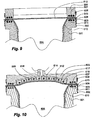
- a heat welding apparatus comprises a cylindrical aluminum alloy welding bolster 501 having an outer cylindrical face 502, a flat annular top face 503 and a central bore 504 that narrows in a direction away from top face 503.
- An extruded polyurethane tube 510 is disposed in the bore 504 of the welding bolster 501 and mounted by folding its one end section 511 so as to overlap the flat top face 503 and an adjoining portion of the cylindrical external face 502.
- To facilitate folding the diameter of the welding bolster 501 at the cylindrical external face 502 is slightly smaller than the inner diameter of the polymer tube 510.
- a circular sheet 512 of same polymer material as the tube member 510 of larger diameter than the diameter of the welding bolster 501 is placed on top of the tube member 510.
- the sheet 512 is secured in this position by posing an annular holder 505 of same material as the welding bolster 501 axially aligned with the axis of the welding bolster 501 on the sheet 512.
- the welding bolster 501 and/or the holder 505 is equipped with insulated resistive heating wires 506, 507 disposed below or above, respectively, of the annular top face 503 or a corresponding flat face on the holder 505.
- the flat faces of the bolster 501 and/or the holder 505 are heated to a fusing temperature of the polymer material of the tube 510 and the sheet 511 for a time sufficient to substantially soften or melt the clamped portions of the tube 510 and the sheet 512, which are thereby bonded to each other.
- Portions 511, 513 of the tube 510 and the sheet 512, respectively, disposed externally of the face 503 are cut off by the downward movement of an annular cutter 508.
- the thus produced probe head cover 100 is removed from the apparatus. After turning the probe cover inside out, possibly sterilizing it and/or filling it with a measured amount of ultrasound gel, it is packed, and the package is sealed.
- the probe head cover of the invention can be packed in any desired manner, for instance in a telescopically folded configuration.
- Ultrasound probe covers with differently shaped top members such as those illustrated in Figs. 3 to 6 , can be manufactured by correspondingly formed combinations of welding bolsters and holders.
- the probe head cover 400 of Fig. 6 comprising a domed top member 402 can be manufactured by a similar welding bolster 601 in combination with a welding holder 605 having a negative dome shaped central section 609 provided with electrical resistive heating elements 616 and bores 617 in communication with a vacuum source (not shown) by means of a conduit 618.
- a central portion of the originally flat sheet 612 is softened and drawn in the direction of the domed shaped section 609 of the holder 602. After cooling under vacuum, the central portion of the sheet 612 has assumed a permanent domed shape.
- Elements in Fig. 10 nos. 602, 603, 604, 606, 607, 608, 610, 611, 613 are functionally equivalent to elements 502, 503, 504, 506, 507, 508, 510, 511, 512, respectively, of the apparatus of Fig. 9 .
- the tube and top members of the invention can also be connected by means of an adhesive.
- apparatus similar to those of Figs. 9 and 10 can be used, in which heating elements 503, 507 and 603, 607, respectively, have been omitted.
- an adhesive is applied on the free face of the tube member 510; 610 facing away from the face 503; 603 of the bolster 501; 601, whereupon the sheet 512; 612 is placed on and pressed against the adhesive bearing free face of the sheet 510; 610.
- the connection is finished by allowing the solvent to evaporate.
- Adhesives suitable for polyurethane probe covers comprise solutions of polyurethane, such as hydroxyl terminated polyurethane, in an organic solvent such as acetone or methyl ethyl ketone.
- polyurethane such as hydroxyl terminated polyurethane
- organic solvent such as acetone or methyl ethyl ketone.
- Other kinds of adhesives, such as reactive polyurethane adhesives, can also be used.
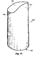
- the embodiment of the probe cover 700 of the invention illustrated in Fig. 11 differs from the other embodiments in that the rectangular top member 702 with rounded short sides is attached to a tube member 701 of which the top edge 704 does not extend perpendicularly to the tube member axis, that is, in one plane. Since the top edge 704 is wavy, the top member 702 is not flat but bent, the distance of its short sides to the proximal edge 705 of the tube member 701 being shorter than of its central portion.
- the probe cover 700 can be manufactured, for instance, by a welding bolster/holder apparatus with saddle formed contact faces corresponding to the annular top face 503 or the corresponding annular face on the holder 505, respectively, of the welding apparatus of Fig 9 .
- Figs. 12 - 12c illustrate exemplary non-cylindrical tube members 800, 900, 100, 1100 of the invention made by thermoforming of cylindrical tube blanks.
- Reference nos. 810, 910, 1010, 1110 indicate the front ends of the members 800, 900, 100, 1100, respectively at which top members of desired shape can be mounted by welding or by use of an adhesive.
- the tube members 800 and 1200 comprise a throat.
- the lumen of the tube members 900 (frustrum of a cone) and 1000 is narrowing in the direction of their front ends 910, 1010.
Landscapes
- Health & Medical Sciences (AREA)
- Life Sciences & Earth Sciences (AREA)
- Surgery (AREA)
- Biomedical Technology (AREA)
- Medical Informatics (AREA)
- Veterinary Medicine (AREA)
- Public Health (AREA)
- Engineering & Computer Science (AREA)
- General Health & Medical Sciences (AREA)
- Heart & Thoracic Surgery (AREA)
- Animal Behavior & Ethology (AREA)
- Molecular Biology (AREA)
- Biophysics (AREA)
- Nuclear Medicine, Radiotherapy & Molecular Imaging (AREA)
- Physics & Mathematics (AREA)
- Radiology & Medical Imaging (AREA)
- Pathology (AREA)
- Optics & Photonics (AREA)
- Ultra Sonic Daignosis Equipment (AREA)
Description
- The present invention relates to an ultrasound probe cover and a method for its manufacture.
- Ultrasound probes cannot be easily sterilized. To protect the patient from microbial contamination ultrasound probes used in diagnosis therefore are inserted into a thin sheath of polymer material. Since air is a bad ultrasound conductor, air bubbles between the probe and the sheath have to be avoided. This is accomplished by filling the lumen of the probe partially with an aqueous ultrasound conducting gel, which provides ultrasound conducting contact between the probe and the inner face of the sheath. It is also clinically necessary to provide such gel to the outer face of the sheath, although this aspect is of no interest to the present invention.
- A great number of ultrasound probe covers are known in the art. They comprise or consist of a tubular sheath of plastic material closed at its one, front end, or of dipped covers made from latex, neoprene, chloroprene and other resilient polymers. Known tubular sheaths of polymer material usually have welded seams along their entire length, which increases their risk for leakage. Prior to use the ultrasound probe is inserted through the open rear end of the sheath and displaced in the direction of the front end until abutment with the inner face of the latter. While some ultrasound probe covers are marketed partially filled with ultrasound conducting gel at their front end portion other probe covers are filled with gel prior to use.
- Ultrasound probe covers known in the art are made from thin polymer foil. The foil is cut to appropriate shape and heat sealed at its edges to form a tube with a closed end and an open end. A problem with ultrasound probes of this kind is their bad fit with ultrasound probe heads. Another, concomitant problem is the existence of ears and other kind of more or less sharp protrusions of polymer material at the closed end portion of the cover, which ears or other protrusions are irritating and may even damage sensitive mucosa in the body cavities into which the ultrasound probe provided with the cover is inserted. The protruding portions of the cover are at risk to be penetrated by a biopsy needle disposed in close proximity of the probe head, which would destroy the sterile barrier formed by the cover. Protruding portions of the sheath may also hinder the mounting of a biopsy needle guide on the probe.
- While ultrasound probe covers made by a dipping process do not have these drawbacks, they are generally more expensive, difficult to make in larger size, and sometimes allergenic, e.g., if made of latex.
-
US 4 887 615 -
EP 0 477 581 discloses an ultrasound probe cover consisting of a plastic foil tube wherein one end is closed by welding and wherein the weld seam lies on the inside. -
EP 0 104 618 A2 describes a probe cover that is made of a puncture-proof cap and a flexible tubular extension, but there is no mentioning of a process of manufacturing said probe cover and protruding seams seem to be unavoidable. - A first object of the invention is to provide an ultrasound probe cover that is well adapted to ultrasound probe heads used in the art.
- Another object of the invention is to provide an ultrasound probe cover that does not irritate or damage sensitive mucosa in the body of a patient.
- Still another object of the invention is to provide an ultrasound probe cover fitting well to the probe head and lacking protruding portions that risk to be penetrated by a biopsy needle disposed in close proximity of the probe head or which may complicate the mounting of a needle guide attachment.
- Further objects of the invention will become evident from the following summary of the invention, the description of a number of preferred embodiments illustrated in a drawing, and the appended claims.
- According to the present invention an ultrasound probe cover is disclosed comprising a flexible polymer tube member having an open first end and a second end closed by a top member of preferably same material and wherein the originally separate tube and top members are joined to each other adhesively. "Adhesively" includes the integration of the tube and top members at the joint by heating the portions of the material to be joined in an abutting relationship under pressure to a welding temperature or by use of an adhesive. A preferred adhesive comprises a solution in a suitable organic solvent of a polymer of same kind as the polymer of the tube and top members. A preferred welding temperature is a temperature in the vicinity of the melting point of the polymer. It is preferred for the tube member of the invention to be made by cutting a tube produced by polymer extrusion to appropriate length. The tube member of the invention can be of cylindrical form. Alternatively the tube member of the invention can be of varying diameter, such as having the form of a frustrum of a cone or comprising a throat. A tube member of varying diameter can be made from a cylindrical tube member by, for instance, thermoforming. A tube member produced by polymer extrusion does not comprise a weld or seam. It is however within the ambit of the invention to make the tube member from a polymer tube comprising one or several heat welding or adhesive seams extending in a longitudinal direction of the tube, such as by joining opposite edges of a rectangular piece of polymer foil by heat welding or gluing, respectively. It is preferred for the top member to be of circular or elliptic form or of a rectangular form with rounded corners. It is particularly preferred for the ultrasound probe cover to substantially comprise a tube member and top member of this kind joined in the aforementioned manner. It is also preferred for the top member to not comprise a seam or other discontinuity.
- According to a preferred aspect of the invention, the top member is substantially flat. According to another preferred aspect of the invention, the top member is not flat, for instance it is dome shaped, or comprises a central dome shaped portion. A dome shaped top member or other non-flat top members can be produced by thermoforming to make them fit to probe heads of particular form.
- The probe cover of the invention may be made of any thermoplastic material that is medically acceptable and of which two pieces can be joined by heating them under pressure in an abutting configuration to a welding temperature. Preferred thermoplastic polymer materials for use in the invention include polyethylene, polypropylene, and polyurethane. Polyurethane and polymers comprising polyurethane domains are particularly preferred materials. The thickness of the material of the tube member wall and of the top member is from 4 µm to 200 µm, preferably from 20 µm to 100 µm. It is also preferred for the material of the tube member and of the top member to be of the same thickness. The joining of the tube member and the top member by heat welding produces a seam extending along the periphery of the tube member's second end and of the top member. The seam so produced initially extends outwardly of the probe cover in the form of a narrow flange. The final configuration of the probe cover is obtained by turning it inside out. The probe cover of the invention can be dimensioned so as to suit ultrasound probe heads of a desired size and form.
- According to a further preferred aspect of the invention, the ultrasound probe cover comprises a suitable amount of ultrasound gel in its lumen at its second, distal end, optionally in a distal compartment separated from the main distal portion of the probe cover by a transverse wall. The transverse wall should be arranged easily penetrable by the probe head during the process of insertion of the latter into the probe cover. The transverse wall can be arranged by applying heat and pressure to the flattened tube member along a line perpendicular to the tube axis. A temporarily closed proximal compartment containing ultrasound gel may be also arranged by substituting the transverse wall by clamping the tube member by a clamp or a similar device in a direction transverse to the tube axis distally of the ultrasound gel or by folding the probe cover in a transverse direction distally of the ultrasound gel and temporarily securing the fold from outside.
- Other features and advantages of the present invention will become apparent from the following description of the invention which refers to the accompanying drawings.
- The invention will now be explained in greater detail by reference to preferred embodiments and apparatus for their manufacture illustrated in a rough drawing, in which
- Fig. 1
- is a prior art probe head cover, in a perspective view;
- Fig. 2
- is a prior art cut out sheet of polymer foil from which the prior art probe head cover of
Fig. 1 has been made; - Fig. 3
- is a first embodiment of the probe head cover of the invention, in a perspective view;
- Fig. 4
- is a second embodiment of the probe head cover of the invention, in a perspective view;
- Fig. 5
- is a third embodiment of the probe head cover of the invention, in a perspective view;
- Fig. 6
- is a fourth embodiment of the probe head cover of the invention, in a perspective view;
- Fig. 7
- is an partial axial sectional view of the probe head cover of
Fig. 2 , enlarged and prior to turning it inside out; - Fig. 8
- is the probe head cover of
Fig. 6 turned inside out, in the same enlarged view; - Fig. 9
- is an apparatus for manufacture of the probe head cover of the invention having a flat top member;
- Fig. 10
- is an apparatus for manufacture of the probe head cover of the invention having a domed top member;
- Fig. 11
- is a further embodiment of the probe head cover of the invention, in a perspective view;
- Figs. 12 - 12c
- are axial sections through exemplary non-cylindrical tube members of the invention made by thermoforming cylindrical tube blanks.
- For clarity reasons, the probe head covers of
Figs. 1 to 8 and11 are shown in an inflated state by putting their lumen under a slight positive pressure. For the same reasons, in the figures representing sectional views, the wall thickness of polymer material is greatly exaggerated and dimensions are generally not to scale. - The prior art probe head cover 1 of
Fig. 1 has been made by cutting a thin sheet 2 (Fig. 2 ) of polyurethane to size, plying thesheet 2 along plyinglines corresponding edges cut edges 8, 8' withcut edge 7, cutedge 9 withcut edge 9', and cutedges 10, 10' withcut edge 9 by gluing or welding to formseams corners ears ears - The
embodiment 100 of the ultrasound probe cover of the invention illustrated inFig. 3 comprises atube member 101 of extruded polyurethane having a wall thickness of about 40 µm and a flattop member 102 of polyurethane sheet material of same thickness joined to and closing one (distal) end of thetube member 101. Over acircular flange 103 thetop member 102 is integral with the tube member 101 (Fig. 7 ). The integral joint between themembers Fig. 9 . To avoid contact of theflange 103 and sensitive tissue, theultrasound probe cover 100 is turned inside out (Fig. 8 ) prior to use to assume the configuration shown inFigs. 3 and8 . Thetop member 102 of theultrasound probe cover 100 is circular and of the same diameter as thetube member 101. - Instead of a circular
top member 102, top members of other form can be used, such as an elliptic top member 202 (Fig. 4 ) joined to acylindrical tube member 201 forming aprobe cover 200 or a rectangulartop member 302 with rounded corners (Fig. 5 ) joined to acylindrical tube member 301 forming aprobe cover 300. It is also possible to use top members that are not flat such as, for instance, a dome shapedtop member 402 of the embodiment ofFig. 6 joined to thecylindrical tube member 401 forming aprobe cover 400. The dome shapedtop member 402 or other non-flat top members can be produced, for instance, from a sheet of polymer material by heat forming, in particular by vacuum heat forming. - The integral joint between the tube element and the top element of the probe cover of the invention can be produced in the manner shown in
Figs. 9 and 10 . A heat welding apparatus comprises a cylindrical aluminum alloy welding bolster 501 having an outercylindrical face 502, a flat annulartop face 503 and acentral bore 504 that narrows in a direction away fromtop face 503. An extrudedpolyurethane tube 510 is disposed in thebore 504 of the welding bolster 501 and mounted by folding its oneend section 511 so as to overlap the flattop face 503 and an adjoining portion of the cylindricalexternal face 502. To facilitate folding the diameter of the welding bolster 501 at the cylindricalexternal face 502 is slightly smaller than the inner diameter of thepolymer tube 510. Acircular sheet 512 of same polymer material as thetube member 510 of larger diameter than the diameter of the welding bolster 501 is placed on top of thetube member 510. Thesheet 512 is secured in this position by posing anannular holder 505 of same material as the welding bolster 501 axially aligned with the axis of the welding bolster 501 on thesheet 512. The welding bolster 501 and/or theholder 505 is equipped with insulatedresistive heating wires top face 503 or a corresponding flat face on theholder 505. By these means the flat faces of the bolster 501 and/or theholder 505 are heated to a fusing temperature of the polymer material of thetube 510 and thesheet 511 for a time sufficient to substantially soften or melt the clamped portions of thetube 510 and thesheet 512, which are thereby bonded to each other.Portions tube 510 and thesheet 512, respectively, disposed externally of theface 503 are cut off by the downward movement of anannular cutter 508. After lifting theholder 505, the thus producedprobe head cover 100 is removed from the apparatus. After turning the probe cover inside out, possibly sterilizing it and/or filling it with a measured amount of ultrasound gel, it is packed, and the package is sealed. The probe head cover of the invention can be packed in any desired manner, for instance in a telescopically folded configuration. Ultrasound probe covers with differently shaped top members, such as those illustrated inFigs. 3 to 6 , can be manufactured by correspondingly formed combinations of welding bolsters and holders. Theprobe head cover 400 ofFig. 6 comprising a domedtop member 402 can be manufactured by a similar welding bolster 601 in combination with awelding holder 605 having a negative dome shapedcentral section 609 provided with electricalresistive heating elements 616 and bores 617 in communication with a vacuum source (not shown) by means of aconduit 618. By applying vacuum and heat to thevoid 614, a central portion of the originallyflat sheet 612 is softened and drawn in the direction of the domed shapedsection 609 of theholder 602. After cooling under vacuum, the central portion of thesheet 612 has assumed a permanent domed shape. Elements inFig. 10 nos. 602, 603, 604, 606, 607, 608, 610, 611, 613 are functionally equivalent toelements Fig. 9 . - The tube and top members of the invention can also be connected by means of an adhesive. For this purpose apparatus similar to those of
Figs. 9 and 10 can be used, in whichheating elements tube member tube member 510; 610 facing away from theface 503; 603 of the bolster 501; 601, whereupon thesheet 512; 612 is placed on and pressed against the adhesive bearing free face of thesheet 510; 610. The connection is finished by allowing the solvent to evaporate. Adhesives suitable for polyurethane probe covers comprise solutions of polyurethane, such as hydroxyl terminated polyurethane, in an organic solvent such as acetone or methyl ethyl ketone. Other kinds of adhesives, such as reactive polyurethane adhesives, can also be used. - The embodiment of the
probe cover 700 of the invention illustrated inFig. 11 differs from the other embodiments in that the rectangulartop member 702 with rounded short sides is attached to atube member 701 of which thetop edge 704 does not extend perpendicularly to the tube member axis, that is, in one plane. Since thetop edge 704 is wavy, thetop member 702 is not flat but bent, the distance of its short sides to theproximal edge 705 of thetube member 701 being shorter than of its central portion. Theprobe cover 700 can be manufactured, for instance, by a welding bolster/holder apparatus with saddle formed contact faces corresponding to the annulartop face 503 or the corresponding annular face on theholder 505, respectively, of the welding apparatus ofFig 9 . -
Figs. 12 - 12c illustrate exemplarynon-cylindrical tube members members tube members 800 and 1200 comprise a throat. The lumen of the tube members 900 (frustrum of a cone) and 1000 is narrowing in the direction of theirfront ends - The device and method of the invention will be understood from the foregoing description, and it is apparent that various changes may be made in the form, construct steps, and arrangements of the parts and steps thereof. The forms herein described are merely preferred exemplary embodiments thereof.
- Although the present invention has been described in relation to particular embodiments thereof, many other variations and modifications and other uses will become apparent to those skilled in the art. It is preferred, therefore, that the present invention be limited not by the specific disclosure herein, but only by the appended claims.
Claims (15)
- Ultrasound probe cover comprising a flexible polymer tube member having an open first end and a second end; a seamless top member closing the open first end, and wherein the originally separate tube and top members are joined to each other adhesively by welding or by use of an adhesive forming an outwardly extending flange that is turned inside the probe cover in the final configuration.
- The cover of claim 1, wherein the tube member and the top member are of the same material.
- The cover of claim 1 or 2, wherein the tube member has been cut to size from a tube of polymer material produced by extrusion.
- The cover of any of claims 1 to 3, wherein the top member is of circular or elliptic form or of a rectangular form with rounded corners.
- The cover of any of claims 1 to 3, wherein the top member is substantially flat.
- The cover of any of claims 1 to 3, wherein the top member is dome shaped.
- The cover of any of claims 1 to 6, substantially consisting of said tube member and said top member.
- The cover of any of claims 1 to 7, wherein said cover is comprised of polyethylene, polypropylene or polyurethane.
- The cover of any of claims 1 to 8 having a wall with a thickness of from 4 µm to 200 µm.
- The cover of any of claims 1 to 8 having a wall thickness of from 20 µm to 100 µm.
- The cover of any of claims 1 to 8 having a wall thickness of about 40 µm.
- The cover of any of claims 1 to 11, wherein the cover has a lumen and further comprising ultrasound gel disposed in the lumen adjacent to the top member.
- The cover of claim 12, wherein the cover has a transverse wall or fold proximally of the ultrasound gel.
- A process of making an ultrasound probe cover comprising the steps of:(A) forming a flexible polymer tube member;(B) passing the tube member through an annular heat welding support;(C) folding one end of the tube member over the welding support over an angle of 90° or more;(D) positioning a sheet of seamless polymer foil as top member on a folded portion of the tube member, clamping annular abutting portions of the tube member and the polymer foil against each other;(E) heating the clamped portions to a temperature near the melting point of the polymer for a time sufficient to make them integrate;(F) optionally cooling the integrated portions to a temperature below the melting point of the polymer;(G) optionally cutting off polymer material extending radially outwardly of the support;(H) stopping the clamping;(I) removing the probe cover from the support;(K) turning the probe cover inside out to obtain the final configuration.
- The process of claim 14, further comprising a step of heat forming that is operable to produce a heat shaped top member, in particular a dome shaped top member.
Applications Claiming Priority (2)
| Application Number | Priority Date | Filing Date | Title |
|---|---|---|---|
| US12/167,360 US20100004543A1 (en) | 2008-07-03 | 2008-07-03 | Ultrasound probe cover and method for its manufacture |
| PCT/SE2009/000345 WO2010002313A1 (en) | 2008-07-03 | 2009-07-01 | Ultrasound probe cover and method for its production |
Publications (3)
| Publication Number | Publication Date |
|---|---|
| EP2303381A1 EP2303381A1 (en) | 2011-04-06 |
| EP2303381A4 EP2303381A4 (en) | 2016-11-30 |
| EP2303381B1 true EP2303381B1 (en) | 2020-10-14 |
Family
ID=41464906
Family Applications (1)
| Application Number | Title | Priority Date | Filing Date |
|---|---|---|---|
| EP09773828.0A Active EP2303381B1 (en) | 2008-07-03 | 2009-07-01 | Ultrasound probe cover and method for its production |
Country Status (3)
| Country | Link |
|---|---|
| US (1) | US20100004543A1 (en) |
| EP (1) | EP2303381B1 (en) |
| WO (1) | WO2010002313A1 (en) |
Families Citing this family (39)
| Publication number | Priority date | Publication date | Assignee | Title |
|---|---|---|---|---|
| US8784336B2 (en) | 2005-08-24 | 2014-07-22 | C. R. Bard, Inc. | Stylet apparatuses and methods of manufacture |
| US8388546B2 (en) | 2006-10-23 | 2013-03-05 | Bard Access Systems, Inc. | Method of locating the tip of a central venous catheter |
| US7794407B2 (en) | 2006-10-23 | 2010-09-14 | Bard Access Systems, Inc. | Method of locating the tip of a central venous catheter |
| US10524691B2 (en) | 2007-11-26 | 2020-01-07 | C. R. Bard, Inc. | Needle assembly including an aligned magnetic element |
| US8781555B2 (en) | 2007-11-26 | 2014-07-15 | C. R. Bard, Inc. | System for placement of a catheter including a signal-generating stylet |
| US9456766B2 (en) | 2007-11-26 | 2016-10-04 | C. R. Bard, Inc. | Apparatus for use with needle insertion guidance system |
| CN103750858B (en) | 2007-11-26 | 2017-04-12 | C·R·巴德股份有限公司 | Integrated system for intravascular placement of a catheter |
| US10449330B2 (en) | 2007-11-26 | 2019-10-22 | C. R. Bard, Inc. | Magnetic element-equipped needle assemblies |
| US10751509B2 (en) | 2007-11-26 | 2020-08-25 | C. R. Bard, Inc. | Iconic representations for guidance of an indwelling medical device |
| US9521961B2 (en) | 2007-11-26 | 2016-12-20 | C. R. Bard, Inc. | Systems and methods for guiding a medical instrument |
| US8849382B2 (en) | 2007-11-26 | 2014-09-30 | C. R. Bard, Inc. | Apparatus and display methods relating to intravascular placement of a catheter |
| US9649048B2 (en) | 2007-11-26 | 2017-05-16 | C. R. Bard, Inc. | Systems and methods for breaching a sterile field for intravascular placement of a catheter |
| US8478382B2 (en) * | 2008-02-11 | 2013-07-02 | C. R. Bard, Inc. | Systems and methods for positioning a catheter |
| US9901714B2 (en) | 2008-08-22 | 2018-02-27 | C. R. Bard, Inc. | Catheter assembly including ECG sensor and magnetic assemblies |
| US8437833B2 (en) | 2008-10-07 | 2013-05-07 | Bard Access Systems, Inc. | Percutaneous magnetic gastrostomy |
| CN102802514B (en) | 2009-06-12 | 2015-12-02 | 巴德阿克塞斯系统股份有限公司 | Catheter tip positioning equipment |
| US9445734B2 (en) | 2009-06-12 | 2016-09-20 | Bard Access Systems, Inc. | Devices and methods for endovascular electrography |
| US9532724B2 (en) | 2009-06-12 | 2017-01-03 | Bard Access Systems, Inc. | Apparatus and method for catheter navigation using endovascular energy mapping |
| EP2482719A4 (en) | 2009-09-29 | 2016-03-09 | Bard Inc C R | STYLETS FOR USE WITH APPARATUS FOR INTRAVASCULAR PLACEMENT OF A CATHETER |
| US11103213B2 (en) | 2009-10-08 | 2021-08-31 | C. R. Bard, Inc. | Spacers for use with an ultrasound probe |
| CN102821679B (en) | 2010-02-02 | 2016-04-27 | C·R·巴德股份有限公司 | For the apparatus and method that catheter navigation and end are located |
| ES2778041T3 (en) | 2010-05-28 | 2020-08-07 | Bard Inc C R | Apparatus for use with needle insertion guidance system |
| CA2806353A1 (en) | 2010-08-09 | 2012-02-16 | C.R. Bard Inc. | Support and cover structures for an ultrasound probe head |
| US20120046562A1 (en) | 2010-08-20 | 2012-02-23 | C. R. Bard, Inc. | Reconfirmation of ecg-assisted catheter tip placement |
| EP2632360A4 (en) | 2010-10-29 | 2014-05-21 | Bard Inc C R | Bioimpedance-assisted placement of a medical device |
| CA2835890A1 (en) | 2011-07-06 | 2013-01-10 | C.R. Bard, Inc. | Needle length determination and calibration for insertion guidance system |
| USD724745S1 (en) | 2011-08-09 | 2015-03-17 | C. R. Bard, Inc. | Cap for an ultrasound probe |
| USD699359S1 (en) | 2011-08-09 | 2014-02-11 | C. R. Bard, Inc. | Ultrasound probe head |
| JP5684083B2 (en) | 2011-09-29 | 2015-03-11 | ジーイー・メディカル・システムズ・グローバル・テクノロジー・カンパニー・エルエルシー | Probe cover, ultrasonic probe, and ultrasonic image display device |
| WO2013070775A1 (en) | 2011-11-07 | 2013-05-16 | C.R. Bard, Inc | Ruggedized ultrasound hydrogel insert |
| EP2861153A4 (en) | 2012-06-15 | 2016-10-19 | Bard Inc C R | Apparatus and methods for detection of a removable cap on an ultrasound probe |
| WO2015120256A2 (en) | 2014-02-06 | 2015-08-13 | C.R. Bard, Inc. | Systems and methods for guidance and placement of an intravascular device |
| US10973584B2 (en) | 2015-01-19 | 2021-04-13 | Bard Access Systems, Inc. | Device and method for vascular access |
| US10349890B2 (en) | 2015-06-26 | 2019-07-16 | C. R. Bard, Inc. | Connector interface for ECG-based catheter positioning system |
| US11000207B2 (en) | 2016-01-29 | 2021-05-11 | C. R. Bard, Inc. | Multiple coil system for tracking a medical device |
| JP6856771B2 (en) * | 2017-04-27 | 2021-04-14 | シブコ メディカル インスツルメンツ カンパニー、インコーポレイテッド | Sterilization cover for ultrasonic transducers |
| CN112867443B (en) | 2018-10-16 | 2024-04-26 | 巴德阿克塞斯系统股份有限公司 | Safety equipment connection system and method for establishing electrical connection |
| US12544101B2 (en) | 2019-01-30 | 2026-02-10 | Bard Access Systems, Inc. | Systems and methods for tracking medical devices |
| KR102406068B1 (en) * | 2020-01-31 | 2022-06-08 | 주식회사 세라젬 | Multi functional probe capable of electromagnetic wave shielding |
Citations (1)
| Publication number | Priority date | Publication date | Assignee | Title |
|---|---|---|---|---|
| EP0104618A2 (en) * | 1982-09-24 | 1984-04-04 | Advanced Technology Laboratories, Inc. | Sterile sheath apparatus for intraoperative ultrasound scanning |
Family Cites Families (13)
| Publication number | Priority date | Publication date | Assignee | Title |
|---|---|---|---|---|
| US4887615A (en) * | 1988-12-28 | 1989-12-19 | Microtek Medical Inc. | Sterile drape for ultrasound probe |
| DE9012429U1 (en) * | 1990-08-30 | 1990-10-31 | Johnson & Johnson Medical GmbH, 2000 Norderstedt | Sterile ultrasound cover tube |
| SE505064C2 (en) * | 1995-10-17 | 1997-06-16 | Amedic Ab | probe Protection |
| US5795067A (en) * | 1996-05-07 | 1998-08-18 | Thermoscan, Inc. | Enhanced protective lens cover for an infrared thermometer |
| EP0932821A1 (en) * | 1996-05-07 | 1999-08-04 | Thermoscan Inc. | Protective cover for an infrared thermometer |
| US5676159A (en) * | 1996-11-05 | 1997-10-14 | Janin Group | Ultrasound cover |
| US5997481A (en) * | 1998-02-17 | 1999-12-07 | Ultra Sound Probe Covers, Llc | Probe cover with deformable membrane gel reservoir |
| ES2233332T3 (en) * | 1999-01-19 | 2005-06-16 | Tyco Healthcare Group Lp | COVER AND APPLICATOR FOR SURGICAL INSTRUMENT. |
| US6749584B2 (en) * | 2001-08-17 | 2004-06-15 | Reva Medical, Inc. | Balloon protector sleeve |
| GB2396562A (en) * | 2002-12-28 | 2004-06-30 | Rocket Medical Plc | Cover for a medical probe |
| EP1593337B1 (en) * | 2003-02-11 | 2008-08-13 | Olympus Corporation | Overtube |
| US20100198013A1 (en) * | 2004-08-17 | 2010-08-05 | Kenneth Binmoeller | Sterile endoscopic instrument housing |
| CA2681883A1 (en) * | 2007-04-11 | 2008-10-23 | Tyco Healthcare Group Lp | Endoscopic/laparoscopic introducer sleeve |
-
2008
- 2008-07-03 US US12/167,360 patent/US20100004543A1/en not_active Abandoned
-
2009
- 2009-07-01 EP EP09773828.0A patent/EP2303381B1/en active Active
- 2009-07-01 WO PCT/SE2009/000345 patent/WO2010002313A1/en not_active Ceased
Patent Citations (1)
| Publication number | Priority date | Publication date | Assignee | Title |
|---|---|---|---|---|
| EP0104618A2 (en) * | 1982-09-24 | 1984-04-04 | Advanced Technology Laboratories, Inc. | Sterile sheath apparatus for intraoperative ultrasound scanning |
Also Published As
| Publication number | Publication date |
|---|---|
| WO2010002313A1 (en) | 2010-01-07 |
| US20100004543A1 (en) | 2010-01-07 |
| EP2303381A4 (en) | 2016-11-30 |
| EP2303381A1 (en) | 2011-04-06 |
Similar Documents
| Publication | Publication Date | Title |
|---|---|---|
| US20100004543A1 (en) | Ultrasound probe cover and method for its manufacture | |
| EP0365993B1 (en) | Catheter equipped with expansible member and method of manufacturing the same | |
| JP4722298B2 (en) | Inflatable balloon catheter sealing structure and method | |
| US5250069A (en) | Catheter equipped with expansible member and production method thereof | |
| US5088994A (en) | Drip-feed bag and method for manufacturing same | |
| US10850075B2 (en) | Balloon catheter and manufacturing method of elongated member for balloon catheter | |
| JP6682547B2 (en) | Balloon catheter and method for manufacturing long member for balloon catheter | |
| CN107405469B (en) | Catheter and its manufacturing method | |
| CN102892452A (en) | Catheter assembly including container to hold catheter and wetting fluid bag | |
| PT91260B (en) | MANUFACTURING AND CONDITIONING PROCESS OF A BAG DISTRIBUTOR, SUBCONTRACTORS AND CORRESPONDING DISTRIBUTORS | |
| US5676159A (en) | Ultrasound cover | |
| EP0349640A1 (en) | Catheter equipped with expansible member and production thereof | |
| JP2008525105A (en) | Catheter assembly with tapered joint and method for manufacturing the same | |
| WO2018161768A1 (en) | Specimen bag formed by fusion bonding of folding sections thereof and specimen removal instrument | |
| JP4429581B2 (en) | Bag making method | |
| JPH042363A (en) | Balloon catheter | |
| US20150112327A1 (en) | Electrode assembly for catheter system including thermoplastic-based struts | |
| US6165114A (en) | Arrangement for manufacturing a can | |
| JP6528463B2 (en) | CATHETER AND METHOD OF MANUFACTURING THE SAME | |
| EP0200483B1 (en) | Tube insert for pouch weld | |
| JPH02271873A (en) | Catheter with expanding body and production thereof | |
| JP2004350901A (en) | Guide wire insertion port forming method | |
| CN110461403B (en) | Balloon catheter and method for manufacturing medical elongated body | |
| ES2842932T3 (en) | Ultrasound probe cover and method for its production | |
| JPH0144339B2 (en) |
Legal Events
| Date | Code | Title | Description |
|---|---|---|---|
| PUAI | Public reference made under article 153(3) epc to a published international application that has entered the european phase |
Free format text: ORIGINAL CODE: 0009012 |
|
| 17P | Request for examination filed |
Effective date: 20110203 |
|
| AK | Designated contracting states |
Kind code of ref document: A1 Designated state(s): AT BE BG CH CY CZ DE DK EE ES FI FR GB GR HR HU IE IS IT LI LT LU LV MC MK MT NL NO PL PT RO SE SI SK TR |
|
| AX | Request for extension of the european patent |
Extension state: AL BA RS |
|
| DAX | Request for extension of the european patent (deleted) | ||
| RAP1 | Party data changed (applicant data changed or rights of an application transferred) |
Owner name: ASCENDIA AB |
|
| RAP1 | Party data changed (applicant data changed or rights of an application transferred) |
Owner name: ASCENDIA AB |
|
| REG | Reference to a national code |
Ref country code: DE Ref legal event code: R079 Ref document number: 602009062924 Country of ref document: DE Free format text: PREVIOUS MAIN CLASS: A61M0025000000 Ipc: A61B0008000000 |
|
| RA4 | Supplementary search report drawn up and despatched (corrected) |
Effective date: 20161031 |
|
| RIC1 | Information provided on ipc code assigned before grant |
Ipc: A61B 46/17 20160101ALI20161025BHEP Ipc: A61B 8/00 20060101AFI20161025BHEP Ipc: A61B 1/00 20060101ALI20161025BHEP |
|
| STAA | Information on the status of an ep patent application or granted ep patent |
Free format text: STATUS: EXAMINATION IS IN PROGRESS |
|
| 17Q | First examination report despatched |
Effective date: 20190529 |
|
| GRAP | Despatch of communication of intention to grant a patent |
Free format text: ORIGINAL CODE: EPIDOSNIGR1 |
|
| STAA | Information on the status of an ep patent application or granted ep patent |
Free format text: STATUS: GRANT OF PATENT IS INTENDED |
|
| INTG | Intention to grant announced |
Effective date: 20200424 |
|
| GRAS | Grant fee paid |
Free format text: ORIGINAL CODE: EPIDOSNIGR3 |
|
| GRAA | (expected) grant |
Free format text: ORIGINAL CODE: 0009210 |
|
| STAA | Information on the status of an ep patent application or granted ep patent |
Free format text: STATUS: THE PATENT HAS BEEN GRANTED |
|
| AK | Designated contracting states |
Kind code of ref document: B1 Designated state(s): AT BE BG CH CY CZ DE DK EE ES FI FR GB GR HR HU IE IS IT LI LT LU LV MC MK MT NL NO PL PT RO SE SI SK TR |
|
| REG | Reference to a national code |
Ref country code: GB Ref legal event code: FG4D |
|
| REG | Reference to a national code |
Ref country code: AT Ref legal event code: REF Ref document number: 1322773 Country of ref document: AT Kind code of ref document: T Effective date: 20201015 Ref country code: CH Ref legal event code: EP |
|
| REG | Reference to a national code |
Ref country code: DE Ref legal event code: R096 Ref document number: 602009062924 Country of ref document: DE |
|
| REG | Reference to a national code |
Ref country code: IE Ref legal event code: FG4D |
|
| REG | Reference to a national code |
Ref country code: SE Ref legal event code: TRGR |
|
| REG | Reference to a national code |
Ref country code: AT Ref legal event code: MK05 Ref document number: 1322773 Country of ref document: AT Kind code of ref document: T Effective date: 20201014 |
|
| REG | Reference to a national code |
Ref country code: NL Ref legal event code: MP Effective date: 20201014 |
|
| PG25 | Lapsed in a contracting state [announced via postgrant information from national office to epo] |
Ref country code: GR Free format text: LAPSE BECAUSE OF FAILURE TO SUBMIT A TRANSLATION OF THE DESCRIPTION OR TO PAY THE FEE WITHIN THE PRESCRIBED TIME-LIMIT Effective date: 20210115 Ref country code: FI Free format text: LAPSE BECAUSE OF FAILURE TO SUBMIT A TRANSLATION OF THE DESCRIPTION OR TO PAY THE FEE WITHIN THE PRESCRIBED TIME-LIMIT Effective date: 20201014 Ref country code: NL Free format text: LAPSE BECAUSE OF FAILURE TO SUBMIT A TRANSLATION OF THE DESCRIPTION OR TO PAY THE FEE WITHIN THE PRESCRIBED TIME-LIMIT Effective date: 20201014 Ref country code: PT Free format text: LAPSE BECAUSE OF FAILURE TO SUBMIT A TRANSLATION OF THE DESCRIPTION OR TO PAY THE FEE WITHIN THE PRESCRIBED TIME-LIMIT Effective date: 20210215 Ref country code: NO Free format text: LAPSE BECAUSE OF FAILURE TO SUBMIT A TRANSLATION OF THE DESCRIPTION OR TO PAY THE FEE WITHIN THE PRESCRIBED TIME-LIMIT Effective date: 20210114 |
|
| REG | Reference to a national code |
Ref country code: LT Ref legal event code: MG4D |
|
| PG25 | Lapsed in a contracting state [announced via postgrant information from national office to epo] |
Ref country code: PL Free format text: LAPSE BECAUSE OF FAILURE TO SUBMIT A TRANSLATION OF THE DESCRIPTION OR TO PAY THE FEE WITHIN THE PRESCRIBED TIME-LIMIT Effective date: 20201014 Ref country code: LV Free format text: LAPSE BECAUSE OF FAILURE TO SUBMIT A TRANSLATION OF THE DESCRIPTION OR TO PAY THE FEE WITHIN THE PRESCRIBED TIME-LIMIT Effective date: 20201014 Ref country code: BG Free format text: LAPSE BECAUSE OF FAILURE TO SUBMIT A TRANSLATION OF THE DESCRIPTION OR TO PAY THE FEE WITHIN THE PRESCRIBED TIME-LIMIT Effective date: 20210114 Ref country code: AT Free format text: LAPSE BECAUSE OF FAILURE TO SUBMIT A TRANSLATION OF THE DESCRIPTION OR TO PAY THE FEE WITHIN THE PRESCRIBED TIME-LIMIT Effective date: 20201014 Ref country code: IS Free format text: LAPSE BECAUSE OF FAILURE TO SUBMIT A TRANSLATION OF THE DESCRIPTION OR TO PAY THE FEE WITHIN THE PRESCRIBED TIME-LIMIT Effective date: 20210214 |
|
| PG25 | Lapsed in a contracting state [announced via postgrant information from national office to epo] |
Ref country code: HR Free format text: LAPSE BECAUSE OF FAILURE TO SUBMIT A TRANSLATION OF THE DESCRIPTION OR TO PAY THE FEE WITHIN THE PRESCRIBED TIME-LIMIT Effective date: 20201014 |
|
| REG | Reference to a national code |
Ref country code: DE Ref legal event code: R097 Ref document number: 602009062924 Country of ref document: DE Ref country code: ES Ref legal event code: FG2A Ref document number: 2842932 Country of ref document: ES Kind code of ref document: T3 Effective date: 20210715 |
|
| PG25 | Lapsed in a contracting state [announced via postgrant information from national office to epo] |
Ref country code: CZ Free format text: LAPSE BECAUSE OF FAILURE TO SUBMIT A TRANSLATION OF THE DESCRIPTION OR TO PAY THE FEE WITHIN THE PRESCRIBED TIME-LIMIT Effective date: 20201014 Ref country code: EE Free format text: LAPSE BECAUSE OF FAILURE TO SUBMIT A TRANSLATION OF THE DESCRIPTION OR TO PAY THE FEE WITHIN THE PRESCRIBED TIME-LIMIT Effective date: 20201014 Ref country code: RO Free format text: LAPSE BECAUSE OF FAILURE TO SUBMIT A TRANSLATION OF THE DESCRIPTION OR TO PAY THE FEE WITHIN THE PRESCRIBED TIME-LIMIT Effective date: 20201014 Ref country code: SK Free format text: LAPSE BECAUSE OF FAILURE TO SUBMIT A TRANSLATION OF THE DESCRIPTION OR TO PAY THE FEE WITHIN THE PRESCRIBED TIME-LIMIT Effective date: 20201014 Ref country code: LT Free format text: LAPSE BECAUSE OF FAILURE TO SUBMIT A TRANSLATION OF THE DESCRIPTION OR TO PAY THE FEE WITHIN THE PRESCRIBED TIME-LIMIT Effective date: 20201014 |
|
| PLBE | No opposition filed within time limit |
Free format text: ORIGINAL CODE: 0009261 |
|
| STAA | Information on the status of an ep patent application or granted ep patent |
Free format text: STATUS: NO OPPOSITION FILED WITHIN TIME LIMIT |
|
| PG25 | Lapsed in a contracting state [announced via postgrant information from national office to epo] |
Ref country code: DK Free format text: LAPSE BECAUSE OF FAILURE TO SUBMIT A TRANSLATION OF THE DESCRIPTION OR TO PAY THE FEE WITHIN THE PRESCRIBED TIME-LIMIT Effective date: 20201014 |
|
| 26N | No opposition filed |
Effective date: 20210715 |
|
| PG25 | Lapsed in a contracting state [announced via postgrant information from national office to epo] |
Ref country code: SI Free format text: LAPSE BECAUSE OF FAILURE TO SUBMIT A TRANSLATION OF THE DESCRIPTION OR TO PAY THE FEE WITHIN THE PRESCRIBED TIME-LIMIT Effective date: 20201014 |
|
| REG | Reference to a national code |
Ref country code: CH Ref legal event code: PL |
|
| PG25 | Lapsed in a contracting state [announced via postgrant information from national office to epo] |
Ref country code: MC Free format text: LAPSE BECAUSE OF FAILURE TO SUBMIT A TRANSLATION OF THE DESCRIPTION OR TO PAY THE FEE WITHIN THE PRESCRIBED TIME-LIMIT Effective date: 20201014 |
|
| PG25 | Lapsed in a contracting state [announced via postgrant information from national office to epo] |
Ref country code: LI Free format text: LAPSE BECAUSE OF NON-PAYMENT OF DUE FEES Effective date: 20210731 Ref country code: CH Free format text: LAPSE BECAUSE OF NON-PAYMENT OF DUE FEES Effective date: 20210731 |
|
| PG25 | Lapsed in a contracting state [announced via postgrant information from national office to epo] |
Ref country code: IS Free format text: LAPSE BECAUSE OF FAILURE TO SUBMIT A TRANSLATION OF THE DESCRIPTION OR TO PAY THE FEE WITHIN THE PRESCRIBED TIME-LIMIT Effective date: 20210214 Ref country code: LU Free format text: LAPSE BECAUSE OF NON-PAYMENT OF DUE FEES Effective date: 20210701 |
|
| PG25 | Lapsed in a contracting state [announced via postgrant information from national office to epo] |
Ref country code: IE Free format text: LAPSE BECAUSE OF NON-PAYMENT OF DUE FEES Effective date: 20210701 |
|
| PG25 | Lapsed in a contracting state [announced via postgrant information from national office to epo] |
Ref country code: HU Free format text: LAPSE BECAUSE OF FAILURE TO SUBMIT A TRANSLATION OF THE DESCRIPTION OR TO PAY THE FEE WITHIN THE PRESCRIBED TIME-LIMIT; INVALID AB INITIO Effective date: 20090701 Ref country code: CY Free format text: LAPSE BECAUSE OF FAILURE TO SUBMIT A TRANSLATION OF THE DESCRIPTION OR TO PAY THE FEE WITHIN THE PRESCRIBED TIME-LIMIT Effective date: 20201014 |
|
| PGFP | Annual fee paid to national office [announced via postgrant information from national office to epo] |
Ref country code: ES Payment date: 20230907 Year of fee payment: 15 |
|
| PG25 | Lapsed in a contracting state [announced via postgrant information from national office to epo] |
Ref country code: MK Free format text: LAPSE BECAUSE OF FAILURE TO SUBMIT A TRANSLATION OF THE DESCRIPTION OR TO PAY THE FEE WITHIN THE PRESCRIBED TIME-LIMIT Effective date: 20201014 |
|
| PG25 | Lapsed in a contracting state [announced via postgrant information from national office to epo] |
Ref country code: MT Free format text: LAPSE BECAUSE OF FAILURE TO SUBMIT A TRANSLATION OF THE DESCRIPTION OR TO PAY THE FEE WITHIN THE PRESCRIBED TIME-LIMIT Effective date: 20201014 |
|
| PGFP | Annual fee paid to national office [announced via postgrant information from national office to epo] |
Ref country code: DE Payment date: 20240719 Year of fee payment: 16 |
|
| REG | Reference to a national code |
Ref country code: ES Ref legal event code: FD2A Effective date: 20250826 |
|
| PG25 | Lapsed in a contracting state [announced via postgrant information from national office to epo] |
Ref country code: ES Free format text: LAPSE BECAUSE OF NON-PAYMENT OF DUE FEES Effective date: 20240702 |
|
| PGFP | Annual fee paid to national office [announced via postgrant information from national office to epo] |
Ref country code: IT Payment date: 20250703 Year of fee payment: 17 |
|
| PGFP | Annual fee paid to national office [announced via postgrant information from national office to epo] |
Ref country code: BE Payment date: 20250718 Year of fee payment: 17 |
|
| PGFP | Annual fee paid to national office [announced via postgrant information from national office to epo] |
Ref country code: FR Payment date: 20250724 Year of fee payment: 17 |
|
| PGFP | Annual fee paid to national office [announced via postgrant information from national office to epo] |
Ref country code: SE Payment date: 20250819 Year of fee payment: 17 |
|
| PG25 | Lapsed in a contracting state [announced via postgrant information from national office to epo] |
Ref country code: TR Free format text: LAPSE BECAUSE OF FAILURE TO SUBMIT A TRANSLATION OF THE DESCRIPTION OR TO PAY THE FEE WITHIN THE PRESCRIBED TIME-LIMIT Effective date: 20201014 |
|
| REG | Reference to a national code |
Ref country code: DE Ref legal event code: R119 Ref document number: 602009062924 Country of ref document: DE |
|
| PG25 | Lapsed in a contracting state [announced via postgrant information from national office to epo] |
Ref country code: DE Free format text: LAPSE BECAUSE OF NON-PAYMENT OF DUE FEES Effective date: 20260203 |
|
| PGFP | Annual fee paid to national office [announced via postgrant information from national office to epo] |
Ref country code: GB Payment date: 20260629 Year of fee payment: 18 |