EP2303098B1 - Dispositif de déplacement controlé en translation d'un élément allongé - Google Patents
Dispositif de déplacement controlé en translation d'un élément allongé Download PDFInfo
- Publication number
- EP2303098B1 EP2303098B1 EP09766000.5A EP09766000A EP2303098B1 EP 2303098 B1 EP2303098 B1 EP 2303098B1 EP 09766000 A EP09766000 A EP 09766000A EP 2303098 B1 EP2303098 B1 EP 2303098B1
- Authority
- EP
- European Patent Office
- Prior art keywords
- elongated element
- shaft
- actuator
- linear
- motor
- Prior art date
- Legal status (The legal status is an assumption and is not a legal conclusion. Google has not performed a legal analysis and makes no representation as to the accuracy of the status listed.)
- Not-in-force
Links
Images



Classifications
-
- A—HUMAN NECESSITIES
- A61—MEDICAL OR VETERINARY SCIENCE; HYGIENE
- A61M—DEVICES FOR INTRODUCING MEDIA INTO, OR ONTO, THE BODY; DEVICES FOR TRANSDUCING BODY MEDIA OR FOR TAKING MEDIA FROM THE BODY; DEVICES FOR PRODUCING OR ENDING SLEEP OR STUPOR
- A61M25/00—Catheters; Hollow probes
- A61M25/01—Introducing, guiding, advancing, emplacing or holding catheters
- A61M25/09—Guide wires
- A61M25/09041—Mechanisms for insertion of guide wires
-
- A—HUMAN NECESSITIES
- A61—MEDICAL OR VETERINARY SCIENCE; HYGIENE
- A61B—DIAGNOSIS; SURGERY; IDENTIFICATION
- A61B1/00—Instruments for performing medical examinations of the interior of cavities or tubes of the body by visual or photographical inspection, e.g. endoscopes; Illuminating arrangements therefor
- A61B1/00131—Accessories for endoscopes
- A61B1/00133—Drive units for endoscopic tools inserted through or with the endoscope
-
- A—HUMAN NECESSITIES
- A61—MEDICAL OR VETERINARY SCIENCE; HYGIENE
- A61B—DIAGNOSIS; SURGERY; IDENTIFICATION
- A61B1/00—Instruments for performing medical examinations of the interior of cavities or tubes of the body by visual or photographical inspection, e.g. endoscopes; Illuminating arrangements therefor
- A61B1/012—Instruments for performing medical examinations of the interior of cavities or tubes of the body by visual or photographical inspection, e.g. endoscopes; Illuminating arrangements therefor characterised by internal passages or accessories therefor
- A61B1/018—Instruments for performing medical examinations of the interior of cavities or tubes of the body by visual or photographical inspection, e.g. endoscopes; Illuminating arrangements therefor characterised by internal passages or accessories therefor for receiving instruments
-
- A—HUMAN NECESSITIES
- A61—MEDICAL OR VETERINARY SCIENCE; HYGIENE
- A61B—DIAGNOSIS; SURGERY; IDENTIFICATION
- A61B34/00—Computer-aided surgery; Manipulators or robots specially adapted for use in surgery
- A61B34/70—Manipulators specially adapted for use in surgery
- A61B34/71—Manipulators operated by drive cable mechanisms
-
- A—HUMAN NECESSITIES
- A41—WEARING APPAREL
- A41H—APPLIANCES OR METHODS FOR MAKING CLOTHES, e.g. FOR DRESS-MAKING OR FOR TAILORING, NOT OTHERWISE PROVIDED FOR
- A41H37/00—Machines, appliances or methods for setting fastener-elements on garments
-
- A—HUMAN NECESSITIES
- A61—MEDICAL OR VETERINARY SCIENCE; HYGIENE
- A61B—DIAGNOSIS; SURGERY; IDENTIFICATION
- A61B17/00—Surgical instruments, devices or methods
-
- A—HUMAN NECESSITIES
- A61—MEDICAL OR VETERINARY SCIENCE; HYGIENE
- A61B—DIAGNOSIS; SURGERY; IDENTIFICATION
- A61B34/00—Computer-aided surgery; Manipulators or robots specially adapted for use in surgery
- A61B34/30—Surgical robots
-
- A—HUMAN NECESSITIES
- A61—MEDICAL OR VETERINARY SCIENCE; HYGIENE
- A61B—DIAGNOSIS; SURGERY; IDENTIFICATION
- A61B34/00—Computer-aided surgery; Manipulators or robots specially adapted for use in surgery
- A61B34/70—Manipulators specially adapted for use in surgery
-
- A—HUMAN NECESSITIES
- A61—MEDICAL OR VETERINARY SCIENCE; HYGIENE
- A61M—DEVICES FOR INTRODUCING MEDIA INTO, OR ONTO, THE BODY; DEVICES FOR TRANSDUCING BODY MEDIA OR FOR TAKING MEDIA FROM THE BODY; DEVICES FOR PRODUCING OR ENDING SLEEP OR STUPOR
- A61M25/00—Catheters; Hollow probes
- A61M25/01—Introducing, guiding, advancing, emplacing or holding catheters
- A61M25/09—Guide wires
- A61M2025/09116—Design of handles or shafts or gripping surfaces thereof for manipulating guide wires
-
- B—PERFORMING OPERATIONS; TRANSPORTING
- B21—MECHANICAL METAL-WORKING WITHOUT ESSENTIALLY REMOVING MATERIAL; PUNCHING METAL
- B21J—FORGING; HAMMERING; PRESSING METAL; RIVETING; FORGE FURNACES
- B21J15/00—Riveting
- B21J15/10—Riveting machines
- B21J15/28—Control devices specially adapted to riveting machines not restricted to one of the preceding subgroups
-
- B—PERFORMING OPERATIONS; TRANSPORTING
- B31—MAKING ARTICLES OF PAPER, CARDBOARD OR MATERIAL WORKED IN A MANNER ANALOGOUS TO PAPER; WORKING PAPER, CARDBOARD OR MATERIAL WORKED IN A MANNER ANALOGOUS TO PAPER
- B31B—MAKING CONTAINERS OF PAPER, CARDBOARD OR MATERIAL WORKED IN A MANNER ANALOGOUS TO PAPER
- B31B50/00—Making rigid or semi-rigid containers, e.g. boxes or cartons
- B31B50/60—Uniting opposed surfaces or edges; Taping
- B31B50/68—Uniting opposed surfaces or edges; Taping by stitching, stapling or riveting
Definitions
- the present invention generally relates to the displacement in translation and possibly in rotation in both directions of an elongate element, in particular a flexible element, in particular in a conduit or the like, by action at an outer end of said element, in the form of thrust, traction and torsion.
- mini-invasive approaches in different fields involve bringing a flexible instrument in situ via the operating channel of a flexible endoscope or via a catheter.
- the flexible instrument is usually operated manually from the outside under the control of images provided by a visual sensor at the distal end of the endoscope or also by means of an external perioperative sensor (fluoroscope, ultrasound, ).
- the movements of the flexible instrument are mainly translational movements in the operating channel, rotation of the instrument around its axis (when the friction is not too great) and actuation of the distal end of the instrument. instrument (opening / closing forceps, electrocautery actuation, plasma torch activation, etc ).
- a medical instrument is also known in the form of an endoscope or the like, the front end of which, in the patient, is provided with a linear actuator able to move an elongated element in translation.
- this device requires to bring a power supply inside the patient, does not allow manual manipulation of the elongated element, nor its exchange without total extraction of the endoscope.
- This system comprises several actuating units allowing a motorized displacement in translation and rotation of the sheath and a motorized actuation of the instrument.
- the present invention aims to overcome at least some of the aforementioned drawbacks.
- the linear displacement unit disclosed in the latter document has a bulky, heavy and complex constitution, in particular because of the implementation of a mechanism for transforming a rotary movement into a translational movement and the necessary mechanical connection. with the elongated element to move.
- this displacement unit can not be associated, or a fortiori integrated, the control handle of the endoscope and the movement transformation performed necessarily leads to play, detrimental to the accuracy of the movements made.
- the present invention aims to overcome at least some of the aforementioned drawbacks.
- the subject of the present invention is a controlled displacement device according to claim 1.
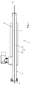
- FIG. 1 , the Figures 5 to 7 and partially Figures 2 to 4 show a displacement device 1 controlled in translation and possibly in rotation of an elongate element 2 terminating in a frontal functional end 3, in particular of an instrument or a tool intended to be brought to an internal site of a patient, more particularly an investigative instrument or a surgical tool disposed in a catheter or in an operating or operating channel 4 of a flexible endoscope 4 ', said device comprising a linear actuator acting at the level of the rear end 3 'of the elongated element 2 located opposite its front functional end 3.
- the actuator 5 consists of a linear motor with direct electromagnetic drive comprising a shaft 6 movable in translation relative to a stator and driving the elongated element 2 and the rear end 3 'of the elongate element 2 comprises a portion 7 allowing the manual manipulation in translation and / or in rotation of the elongated element 2.
- Such a linear electric actuator 5 has no wearing part for the transmission of the movement, and does not require any additional piece for its functional connection with the elongate element 2. Moreover, it is of a simple constitution and a reduced bulk, allows precise control (and without play) and can be easily associated or mounted on an existing body or apparatus ( Fig. 3 and 4 ).
- the elongated element 2 extends through the linear motor 5, which greatly facilitates its interchangeability.
- the attachment of the elongated element 2 with the movable part (shaft 6) of the linear motor 5 can be of different natures, while being advantageously always direct.
- the shaft movable in translation 6 consists of a hollow tube provided with permanent magnets and traversed by the elongated element 2, the latter being secured by magnetization or by clamping with said tubular movable shaft 6.
- the linear motor 5 can then, for example, be of the type known under the name LINMOT (registered name) by the company NTI AG (Switzerland).
- the magnetization connection (between the magnets of the shaft 6 and the elongate element 2 at least partially ferro-magnetic) has a sufficient force for the transmission without sliding traction / thrust movements up to a threshold intensity, while allowing easy release of the elongated member 2 for replacement and sliding by manual action of said member 2 in said hollow shaft 6.
- a mechanical clamping connection by means of a ring or two opposite rings is also possible in connection with the implementation of a hollow shaft 6, possibly in a complementary manner with the magnetic connection, and in particular when the element Elongated 2 is made of a non-magnetic or weakly magnetic material (not shown).
- This embodiment thus has several advantages, among which in particular the possibility of using existing tools and standard instruments (in a ferro-magnetic material or having at least one rear end portion made of such a material, when they are secured to the body).
- the shaft is made by magnetization), the possibility of manually changing instruments and tools 2 in a simple manner and the possibility of joint manipulation or co-manipulation of the tool or instrument 2 with the hand and the motor linear 5.
- connection between the shaft 6 and the elongated element 2 takes place over a relatively long length of the latter, and not in a localized manner, which promotes the transmission of the thrust or traction force.
- the shaft 6 movable in translation is constituted by a portion 2 'of the elongated element 2 having a suitable constitution, that is to say integrating a plurality of permanent magnets in series. Only the supply of the stator 6 'is then necessary.
- the rear end portion 7 of the elongate element 2 protrudes from the linear motor 5, if necessary from the tubular movable shaft 6, and is provided with at least one member 8, 8 'for manual handling of the elongate element 2, possibly in cooperation with the linear motor 5 or in support or replacement thereof (handle 8, ring 8 ').
- the device 1 can also comprise a position sensor of the movable shaft 6, associated or integrated with the motor linear 5, for measuring the actual displacement of the elongated element and its effective depth of depression.
- the device 1 may also comprise a rotary actuator 9 adapted to drive in rotation in a controlled manner.
- elongated element 2 about its longitudinal axis, either in direct engagement or via the tubular movable shaft 6, the portion 7 of the rear end 3 'of the elongated element 2 also protruding from said actuator rotating 9.
- These translational and rotary actuators 9 thus form a controlled external motor unit or module for the displacement of the elongated element 2, with two degrees of freedom controlled.
- the rotary actuator 9 may consist of a hollow shaft motor mounted in alignment coaxial with the linear actuator 5, mechanically secured thereto or with a support 10 possibly carrying this linear actuator 5 and coupled in rotation with the hollow tube or the part 2 'of the elongated element 2 forming the mobile shaft in translation 6, the latter being free to rotate at the level of the linear actuator 5.
- the mechanical attachment and / or the rotational coupling of the hollow shaft motor 9 is (in) t of removable nature.
- the support 10 may for example be provided with a linear guide system of the rotary actuator 9, for example aligned with the longitudinal axis of the elongate element 2 housed in the linear actuator 5.
- the rotary actuator 9 is advantageously provided with a part 9 'of coupling or coupling (mechanical or magnetic) for securing in rotation the tube 6 or the elongate element 2 with said actuator 9, preferably removably.
- the hollow shaft motor 9 may for example be in the form of a motor of the type known under the designation "Servo Actuator” of the company Harmonic Drive Systems Inc.
- the rotary actuator 9 consists of a magnetic motor integrated in the linear motor 5, the shaft 6 thus forming a rotor which can be driven in translation and in rotation.
- the shaft 6 in the form of a tube may then be formed of two parts, namely a first part 12 intended to form the rotor of the rotary actuator 9 and a second part 12 'intended to form the slide (or sliding rotor) of the linear actuator 5.
- the displacement device then comprises, at its through passage receiving the shaft 6, a first stator 6 'intended to interact with the second portion 12' for the translational movement of said shaft 6 and a second stator 11 for interacting with the first portion 12 for rotational displacement of the shaft 6.
- the two stators being axially separated by a magnetically inactive zone, possibly providing a guiding function.
- the rotary actuator 9 consists of an axial motor integrated in the hollow shaft 6 receiving the elongated element 2, this axial motor may consist of a hollow-shaft motor of small diameter (adapted to be integrated in the shaft 6) .
- the rotational connection between the motor 9 and the elongated element 2 is obtained by means of a clamping means, for example of the mandrel type, making it possible to couple the motor 9 to the element 2.
- the translational guidance of the hollow shaft 6 incorporating the hollow shaft axial motor 9 is effected with rotational locking in the linear actuator 5.
- the device 1 comprises or is associated with a control unit, automatic or manual assisted, controlling the displacement of the movable shaft 6 by means of a servocontrol force or speed of the actuator and / or rotary and / or via a position control.
- the control of the displacement device 1 can be automatic in the context of a robotic system for investigation or intervention or be of the manual assisted control type, for example in the form of an electrical control member.
- the subject of the present invention is also, as partially shown by Figures 2 to 4 , an investigation and / or surgery system, in particular a flexible endoscope system 4 ', comprising at least one instrument or tool 2 in the form of a flexible elongated element.
- This system is characterized in that it also comprises at least one device 1 for movement controlled in translation and possibly in rotation as described above, associated with said at least one instrument or tool 2.
- the displacement device 1 may constitute a separate module or unit, but it may also be provided that the linear motor 5 is mounted on the or a control handle 4 "of the system 4 ', as well as possibly the rotary actuator 9. In the latter case, the linear motor 5 is fixed so as not to interfere with the control buttons of the handle 4 ".
- the flexible endoscope system 4 may for example consist of a system as described and shown in the PCT Patent Application No. PCT / FR2008 / 050312 of 25 February 2008 .
- system may further comprise at least one additional actuator capable of controlling the tool or the instrument integrated in the elongated element 2, for example by means of cables, associated with the linear and / or rotary actuator 5, 9.
Landscapes
- Health & Medical Sciences (AREA)
- Life Sciences & Earth Sciences (AREA)
- Surgery (AREA)
- Engineering & Computer Science (AREA)
- Public Health (AREA)
- Animal Behavior & Ethology (AREA)
- Biomedical Technology (AREA)
- Heart & Thoracic Surgery (AREA)
- Veterinary Medicine (AREA)
- General Health & Medical Sciences (AREA)
- Biophysics (AREA)
- Molecular Biology (AREA)
- Nuclear Medicine, Radiotherapy & Molecular Imaging (AREA)
- Medical Informatics (AREA)
- Pathology (AREA)
- Optics & Photonics (AREA)
- Physics & Mathematics (AREA)
- Radiology & Medical Imaging (AREA)
- Pulmonology (AREA)
- Anesthesiology (AREA)
- Hematology (AREA)
- Robotics (AREA)
- Instruments For Viewing The Inside Of Hollow Bodies (AREA)
- Endoscopes (AREA)
- Surgical Instruments (AREA)
Description
- La présente invention concerne de manière générale le déplacement en translation et éventuellement en rotation dans les deux sens d'un élément allongé, en particulier flexible, notamment dans un conduit ou analogue, par action au niveau d'une extrémité extérieure dudit élément, sous forme de poussée, de traction et de torsion.
- Le déplacement contrôlé ou assisté de tels éléments allongés est devenu fréquent dans le domaine médical, compte tenu de l'évolution des techniques d'investigation et d'intervention.
- En effet, de nouvelles approches dites mini-invasives dans différents domaines (chirurgie, gastro-entérologie, radiologie interventionnelle) consistent à amener un instrument flexible in situ par l'intermédiaire du canal opérateur d'un endoscope flexible ou via un cathéter.
- L'instrument flexible est habituellement actionné manuellement de l'extérieur sous le contrôle d'images fournies par un capteur visuel à l'extrémité distale de l'endoscope ou bien également à l'aide d'un capteur per-opératoire externe (fluoroscope, échographe, ...).
- Les mouvements de l'instrument flexible sont principalement des mouvements de translation dans le canal opérateur, de rotation de l'instrument autour de son axe (quand les frottements ne sont pas trop importants) et d'actionnement de l'extrémité distale de l'instrument (ouverture/fermeture pince, actionnement bistouri électrique, activation torche plasma, etc...).
- La commande manuelle de l'endoscope, parfois suivant plusieurs degrés de liberté, simultanément avec la commande des mouvements de l'instrument flexible dans le canal opérateur, demande une très grande coordination oeil-main, particulièrement difficile et fatigante, même pour un praticien expérimenté.
- Il existe par conséquent un besoin de libérer le praticien de certaines des manipulations précitées ou au moins de l'assister dans l'exécution de celles-ci.
- Par les documents
US-A-2005/0215983 et "Design of an Endoluminal NOTES Robotic System", Daniel J. Abbott et al., Proceedings of the 2007 IEEE/RSJ, San Diego, CA, USA, Oct. 29 - Nov. 2 2007, on connaît déjà des dispositifs motorisés de déplacement en translation d'instruments flexibles allongés. Dans ces documents, le déplacement en translation de l'instrument sélectionné parmi une pluralité d'instruments disponible est réalisé au moyen d'un chariot coulissant sur deux rails. - Il s'agit là d'un système mécanique encombrant, sujet à l'usure, nécessitant un espace dégagé important, monté obligatoirement sur un support spécifique et ne permettant pas une rotation de l'instrument par le praticien.
- Par le document
EP 1 857 041 , on connaît par ailleurs un instrument médical sous la forme d'un endoscope ou analogue dont l'extrémité avant, située dans le patient, est pourvue d'un actionneur linéaire apte à déplacer en translation un élément allongé. - Toutefois, ce dispositif nécessite d'amener une alimentation électrique à l'intérieur du patient, ne permet par une manipulation manuelle de l'élément allongé, ni son échange sans extraction totale de l'endoscope.
- Par le document
EP 1 782 744 , on connaît enfin un système endoscopique avec un instrument logé dans une gaine tubulaire. - Ce système comporte plusieurs unités d'actionnement permettant un déplacement motorisé en translation et en rotation de la gaine et un actionnement motorisé de l'instrument.
- Toutefois, ces unités présentent une structure complexe et intègrent toutes des mécanismes de transformation ou de transmission du mouvement.
- De plus, bien que ce système autorise un mode d'actionnement manuel, un démontage préalable de l'ensemble des unités d'actionnement motorisé doit être envisagé.
- La présente invention a pour but de pallier au moins certains des inconvénients précités.
- Néanmoins, l'unité de déplacement linéaire divulguée dans ce dernier document présente une constitution encombrante, lourde et complexe, du fait notamment de la mise en oeuvre d'un mécanisme de transformation d'un mouvement rotatoire en un mouvement translatif et du raccordement mécanique nécessaire avec l'élément allongé à déplacer.
- De plus, cette unité de déplacement ne peut être associée, ni a fortiori intégrée, à la poignée de commande de l'endoscope et la transformation de mouvement réalisée entraîne nécessairement un jeu, préjudiciable à la précision des déplacements effectués.
- La présente invention a pour but de pallier au moins certains des inconvénients précités.
- Ce but est atteint grâce au dispositif de déplacement contrôlé selon la revendication 1.
- A cet effet, la présente invention a pour objet un dispositif de déplacement contrôlé selon la revendication 1.
- L'invention sera mieux comprise, grâce à la description ci-après, qui se rapporte à des modes de réalisation préférés, donnés à titre d'exemples non limitatifs, et expliqués avec référence aux dessins schématiques annexés, dans lesquels :
- la
figure 1 est une représentation schématique partiellement par transparence d'un dispositif de déplacement contrôlé en translation d'un élément allongé selon un premier mode de réalisation de l'invention ; - la
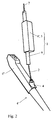
figure 2 est une vue partielle en perspective d'un système d'endoscope flexible comprenant un dispositif de déplacement tel que représenté sur lafigure 1 ; - la
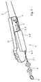
figure 3 est une vue partielle en perspective d'une variante de réalisation du système d'endoscope représenté à lafigure 2 ; - la
figure 4 est une vue partielle similaire à lafigure 3 d'un système d'endoscope flexible comprenant un dispositif de déplacement selon un autre mode de réalisation de l'invention, et, - les
figures 5 à 7 sont des représentations schématiques partiellement par transparence de trois autres modes de réalisation de l'invention, autorisant un déplacement en translation et en rotation de l'élément allongé. - La
figure 1 , lesfigures 5 à 7 et partiellement lesfigures 2 à 4 montrent un dispositif 1 de déplacement contrôlé en translation et éventuellement en rotation d'un élément allongé 2 se terminant par une extrémité fonctionnelle frontale 3, notamment d'un instrument ou d'un outil destiné à être amené au niveau d'un site interne d'un patient, plus particulièrement d'un instrument d'investigation ou d'un outil de chirurgie disposé dans un cathéter ou dans un canal opérateur ou de travail 4 d'un endoscope flexible 4', ledit dispositif comprenant un actionneur linéaire 5 agissant au niveau de l'extrémité arrière 3' de l'élément allongé 2 située à l'opposée de son extrémité fonctionnelle frontale 3. - Conformément à l'invention, l'actionneur 5 consiste en un moteur linéaire à entraînement électromagnétique direct comprenant un arbre 6 mobile en translation par rapport à un stator et entraînant l'élément allongé 2 et l'extrémité arrière 3' de l'élément allongé 2 comporte une portion 7 permettant la manipulation manuelle en translation et/ou en rotation de l'élément allongé 2.
- Un tel actionneur électrique linéaire 5 ne présente aucune pièce d'usure pour la transmission du mouvement, et ne nécessite aucune pièce supplémentaire pour sa solidarisation fonctionnelle avec l'élément allongé 2. De plus, il est d'une constitution simple et d'un encombrement réduit, permet une commande précise (et sans jeu) et peut être aisément associé ou monté sur un organe ou un appareil existant (
Fig. 3 et4 ). - L'élément allongé 2 s'étend à travers le moteur linéaire 5, ce qui facilite grandement son interchangeabilité. La solidarisation de l'élément allongé 2 avec la partie mobile (arbre 6) du moteur linéaire 5 peut être de différentes natures, tout en étant avantageusement toujours directe.
- En accord avec un premier mode de réalisation de l'invention, ressortant des
figures 1 ,2 et3 des dessins annexés, l'arbre mobile en translation 6 consiste en un tube creux pourvu d'aimants permanents et traversé par l'élément allongé 2, ce dernier étant solidarisé par aimantation ou par serrage avec ledit arbre mobile tubulaire 6. - Le moteur linéaire 5 peut alors, par exemple, être du type connu sous la désignation LINMOT (nom déposé) par la société NTI AG (Suisse).
- La liaison par aimantation (entre les aimants de l'arbre 6 et l'élément allongé 2 au moins partiellement ferro-magnétique) présente une force suffisante pour la transmission sans glissement des mouvements de traction/poussée jusqu'à une intensité seuil, tout en permettant un dégagement aisé de l'élément allongé 2 en vue de son remplacement et un coulissement par action manuelle dudit élément 2 dans ledit arbre creux 6.
- Une liaison par serrage mécanique au moyen d'une bague ou de deux bagues opposées, est également possible en relation avec la mise en oeuvre d'un arbre 6 creux, éventuellement de manière complémentaire avec la liaison magnétique, et en particulier lorsque l'élément allongé 2 est réalisé en un matériau amagnétique ou faiblement magnétique (non représenté).
- Ce mode de réalisation présente ainsi plusieurs avantages parmi lesquels notamment la possibilité d'utiliser des outils et des instruments standards existants (en un matériau ferro-magnétique ou présentant au moins une partie d'extrémité arrière en un tel matériau, lorsque leur solidarisation avec l'arbre est réalisée par aimantation), la possibilité de changer manuellement de manière simple les instruments et outils 2 et la possibilité d'une manipulation conjointe ou co-manipulation de l'outil ou de l'instrument 2 avec la main et par le moteur linéaire 5.
- Enfin, la solidarisation entre l'arbre 6 et l'élément allongé 2 s'effectue sur une relative grande longueur de ce dernier, et non pas de manière localisée, ce qui favorise la transmission de l'effort de poussée ou de traction.
- En accord avec un deuxième mode de réalisation, représenté à la
figure 4 des dessins annexés, l'arbre 6 mobile en translation est constitué par une partie 2' de l'élément allongé 2 présentant une constitution adaptée, c'est-à-dire intégrant une pluralité d'aimants permanents en série. Seule la fourniture du stator 6' est alors nécessaire. - La portion 7 d'extrémité arrière de l'élément allongé 2 dépasse du moteur linéaire 5, le cas échéant de l'arbre mobile tubulaire 6, et est pourvue d'au moins un organe 8, 8' pour la manipulation manuelle de l'élément allongé 2, éventuellement en coopération avec le moteur linéaire 5 ou en soutien ou en remplacement de ce dernier (poignée 8, anneau 8').
- Afin de contrôler, le cas échéant, la profondeur et/ou la vitesse d'insertion de l'élément allongé 2, le dispositif 1 peut également comprendre un capteur de position de l'arbre mobile 6, associé ou intégré au moteur linéaire 5, permettant de mesurer le déplacement réel de l'élément allongé et sa profondeur d'enfoncement effective.
- Conformément à un mode de réalisation amélioré de l'invention, et en vue de pouvoir fournir aussi un mouvement commandé en rotation de l'élément allongé 2, le dispositif 1 peut également comprendre un actionneur rotatif 9 apte à entraîner en rotation de manière contrôlée l'élément allongé 2 autour de son axe longitudinal, soit en prise directe, soit par l'intermédiaire de l'arbre mobile tubulaire 6, la portion 7 de l'extrémité arrière 3' de l'élément allongé 2 dépassant également par rapport audit actionneur rotatif 9.
- Ces actionneurs translatif 5 et rotatif 9 forment ainsi une unité ou un module externe de motorisation contrôlée du déplacement de l'élément allongé 2, avec deux degrés de liberté commandée.
- Conformément à une première variante de réalisation, représentée sur la
figure 5 , l'actionneur rotatif 9 peut consister en un moteur à arbre creux monté en alignement coaxial avec l'actionneur linéaire 5, solidarisé mécaniquement avec ce dernier ou avec un support 10 portant éventuellement cet actionneur linéaire 5 et couplé en rotation avec le tube creux ou la partie 2' de l'élément allongé 2 formant l'arbre mobile en translation 6, ce dernier étant libre en rotation au niveau de l'actionneur linéaire 5. - Afin de pouvoir mettre en oeuvre une version dégradée du dispositif 1, de pouvoir changer l'élément allongé 2 ou de pouvoir réaliser des manoeuvres manuelles (passage d'un fonctionnement motorisé à un fonctionnement manuel en cours d'intervention), il peut être prévu que la solidarisation mécanique et/ou le couplage en rotation du moteur à arbre creux 9 soi(en)t de nature amovible.
- Le support 10 peut par exemple être pourvu d'un système de guidage linéaire de l'actionneur rotatif 9, par exemple aligné avec l'axe longitudinal de l'élément allongé 2 logé dans l'actionneur linéaire 5. L'actionneur rotatif 9 est avantageusement pourvu d'une pièce 9' de raccord ou d'accouplement (mécanique ou magnétique) permettant de solidariser en rotation le tube 6 ou l'élément allongé 2 avec ledit actionneur 9, préférentiellement de manière amovible.
- Le moteur à arbre creux 9 peut par exemple se présenter sous la forme d'un moteur du type connu sous la désignation "Servo Actuator" de la société Harmonic Drive Systems Inc.
- Selon une seconde variante de réalisation, et comme le montre la
figure 6 des dessins annexés, l'actionneur rotatif 9 consiste en un moteur magnétique intégré dans le moteur linéaire 5, l'arbre 6 formant ainsi un rotor pouvant être entraîné en translation et en rotation. - L'arbre 6 sous forme de tube peut alors être formé de deux parties, à savoir une première partie 12 destinée à former le rotor de l'actionneur rotatif 9 et une seconde partie 12' destinée à former le coulisseau (ou rotor coulissant) de l'actionneur linéaire 5. Le dispositif de déplacement comporte alors, au niveau de son passage traversant recevant l'arbre 6, un premier stator 6' destiné à interagir avec la seconde partie 12' en vue du déplacement en translation dudit arbre 6 et un second stator 11 destiné à interagir avec la première partie 12 en vue du déplacement en rotation de cet arbre 6. Les deux stators étant séparés axialement par une zone magnétiquement inactive, assurant éventuellement une fonction de guidage.
- Enfin, en accord avec une troisième variante de réalisation, ressortant de la
figure 7 , l'actionneur rotatif 9 consiste en un moteur axial intégré dans l'arbre creux 6 recevant l'élément allongé 2, ce moteur axial pouvant consister en un moteur à arbre creux de faible diamètre (apte à être intégré dans l'arbre 6). - La solidarisation en rotation entre le moteur 9 et l'élément allongé 2 est obtenue par l'intermédiaire d'un moyen de serrage, par exemple de type mandrin, permettant d'accoupler le moteur 9 à l'élément 2.
- Avantageusement, le guidage en translation de l'arbre creux 6 intégrant le moteur axial à arbre creux 9 (par exemple une version miniaturisée du moteur 9 de la première variante précitée) s'effectue avec blocage en rotation dans l'actionneur linéaire 5.
- Enfin, il peut aussi être prévu que le dispositif 1 comprenne ou soit associé à une unité de commande, automatique ou manuelle assistée, contrôlant le déplacement de l'arbre mobile 6 par l'intermédiaire d'un asservissement en effort ou en vitesse de l'actionneur et/ou rotatif et/ou par l'intermédiaire d'un asservissement en position. La commande du dispositif de déplacement 1 peut être automatique dans le cadre d'un système robotisé d'investigation ou d'intervention ou être du type à commande manuelle assistée, par exemple sous la forme d'un organe de commande électrique.
- La présente invention a également pour objet, comme le montrent partiellement les
figures 2 à 4 , un système d'investigation et/ou de chirurgie, en particulier système d'endoscope flexible 4', comprenant au moins un instrument ou outil 2 sous forme d'élément allongé flexible. - Ce système est caractérisé en ce qu'il comprend également au moins un dispositif 1 de déplacement contrôlé en translation et éventuellement en rotation tel que décrit ci-dessus, associé audit au moins un instrument ou outil 2.
- Le dispositif de déplacement 1 peut constituer un module ou une unité séparé(e), mais il peut également être prévu que le moteur linéaire 5 soit monté sur la ou une poignée de commande 4" du système 4', ainsi qu'éventuellement l'actionneur rotatif 9. Dans ce dernier cas, le moteur linéaire 5 est fixé de manière à ne pas interférer avec les boutons de commande de la poignée 4".
- Le système d'endoscope flexible 4' peut par exemple consister en un système tel que décrit et représenté dans la demande de brevet PCT n°
PCT/FR2008/050312 du 25 février 2008 - Enfin, le système peut en outre comprendre au moins un actionneur supplémentaire apte à commander l'outil ou l'instrument intégré à l'élément allongé 2, par exemple par l'intermédiaire de câbles, associé à l'actionneur linéaire et/ou rotatif 5, 9.
- Bien entendu, l'invention n'est pas limitée aux modes de réalisation décrits et représentés aux dessins annexés. Des modifications restent possibles, notamment du point de vue de la constitution des divers éléments ou par substitution d'équivalents techniques, sans sortir pour autant du domaine de protection de l'invention.
Claims (11)
- Dispositif de déplacement contrôlé en translation, et éventuellement en rotation, d'un élément allongé se terminant par une extrémité fonctionnelle frontale, notamment d'un instrument ou d'un outil destiné à être amené au niveau d'un site interne d'un patient, plus particulièrement d'un instrument d'investigation ou d'un outil de chirurgie disposé dans un cathéter ou dans un canal opérateur ou de travail d'un endoscope flexible, ledit dispositif comprenant un actionneur linéaire agissant au niveau de l'extrémité arrière de l'élément allongé située à l'opposée de son extrémité fonctionnelle frontale et à l'extérieur du patient, ledit actionneur (5) consistant en un moteur linéaire à entraînement électromagnétique direct comprenant un arbre (6) mobile en translation par rapport à un stator et entraînant l'élément allongé (2), caractérisé en ce que ledit élément allongé traverse ledit moteur linéaire (5),
en ce que ledit arbre mobile (6) consiste soit en un tube creux pourvu d'aimants permanents et traversé par l'élément allongé (2), avec une solidarisation par aimantation ou serrage avec ledit arbre (6), soit en une partie (2') de l'élément allongé (2) intégrant une pluralité d'aimants permanents en série, et
en ce que l'extrémité arrière (3') de l'élément allongé (2) comporte une portion (7) dépassant du moteur linéaire (5), le cas échéant de l'arbre mobile tubulaire (6), et pourvue d'au moins un organe (8, 8') permettant la manipulation manuelle en translation et/ou en rotation de l'élément allongé (2), en coopération avec le moteur linéaire (5) ou en soutien ou en remplacement de ce dernier. - Dispositif selon la revendication 1, , caractérisé en ce qu'il comprend également un capteur de position de l'arbre mobile (6), associé ou intégré au moteur linéaire (5).
- Dispositif selon l'une quelconque des revendications 1 et 2, caractérisé en ce qu'il comprend également un actionneur rotatif (9) apte à entraîner en rotation de manière contrôlée l'élément allongé (2) autour de son axe longitudinal, soit en prise directe, soit par l'intermédiaire de l'arbre mobile tubulaire (6), la portion (7) de l'extrémité arrière (3') de l'élément allongé (2) dépassant également par rapport audit actionneur rotatif (9).
- Dispositif selon la revendication 3, caractérisé en ce que l'actionneur rotatif (9) consiste en un moteur à arbre creux monté en alignement coaxial avec l'actionneur linéaire (5), solidarisé mécaniquement avec ce dernier ou avec un support (10) portant éventuellement cet actionneur linéaire (5) et couplé en rotation avec le tube creux ou la partie (2') de l'élément allongé (2) formant l'arbre mobile en translation (6), ce dernier étant libre en rotation au niveau de l'actionneur linéaire (5).
- Dispositif selon la revendication 4, caractérisé en ce que la solidarisation mécanique et/ou le couplage en rotation du moteur à arbre creux (9) sont de nature amovible.
- Dispositif selon la revendication 3, caractérisé en ce que l'actionneur rotatif (9) consiste en un moteur magnétique intégré dans le moteur linéaire (5), l'arbre (6) formant ainsi un rotor pouvant être entraîné en translation et en rotation.
- Dispositif selon la revendication 3, caractérisé en ce que l'actionneur rotatif (9) consiste en un moteur axial intégré dans l'arbre creux (6) recevant l'élément allongé (2).
- Dispositif selon l'une quelconque des revendications 1 à 7, caractérisé en ce qu'il comprend en outre une unité de commande (4', 4"), automatique ou manuelle assistée, contrôlant le déplacement de l'arbre mobile (6) par l'intermédiaire d'un asservissement en effort ou en vitesse de l'actionneur linéaire et/ou rotatif et/ou d'un asservissement en position.
- Système d'investigation et/ou de chirurgie, en particulier système d'endoscope flexible, comprenant au moins un instrument ou outil sous forme d'élément allongé flexible, caractérisé en ce qu'il comprend également au moins un dispositif (1) de déplacement contrôlé en translation et éventuellement en rotation selon l'une quelconque des revendications 1 à 8, associé audit au moins un instrument ou outil (2).
- Système selon la revendication 9, caractérisé en ce que le moteur linéaire (5) est monté sur la ou une poignée de commande (4") du système (4'), ainsi qu'éventuellement l'actionneur rotatif (9).
- Système selon la revendication 9 ou 10, caractérisé en ce qu'il comprend en outre au moins un actionneur supplémentaire apte à commander l'outil ou l'instrument intégré à l'élément allongé (2), par exemple par l'intermédiaire de câbles, associé à l'actionneur linéaire et/ou rotatif (5, 9).
Applications Claiming Priority (2)
| Application Number | Priority Date | Filing Date | Title |
|---|---|---|---|
| FR0853422A FR2931599A1 (fr) | 2008-05-26 | 2008-05-26 | Dispositif de deplacement controle en translation d'un element allonge |
| PCT/FR2009/000609 WO2009153438A1 (fr) | 2008-05-26 | 2009-05-26 | Dispositif de deplacement controle en translation d'un element allonge |
Publications (2)
| Publication Number | Publication Date |
|---|---|
| EP2303098A1 EP2303098A1 (fr) | 2011-04-06 |
| EP2303098B1 true EP2303098B1 (fr) | 2016-07-06 |
Family
ID=40260457
Family Applications (1)
| Application Number | Title | Priority Date | Filing Date |
|---|---|---|---|
| EP09766000.5A Not-in-force EP2303098B1 (fr) | 2008-05-26 | 2009-05-26 | Dispositif de déplacement controlé en translation d'un élément allongé |
Country Status (4)
| Country | Link |
|---|---|
| US (1) | US9095686B2 (fr) |
| EP (1) | EP2303098B1 (fr) |
| FR (1) | FR2931599A1 (fr) |
| WO (1) | WO2009153438A1 (fr) |
Cited By (1)
| Publication number | Priority date | Publication date | Assignee | Title |
|---|---|---|---|---|
| DE102021114151A1 (de) | 2021-06-01 | 2022-12-01 | Isys Medizintechnik Gmbh | Instrumentenvorschubvorrichtung und Verwendung einer Spindeleinrichtung bei einer Instrumentenvorschubvorrichtung |
Families Citing this family (24)
| Publication number | Priority date | Publication date | Assignee | Title |
|---|---|---|---|---|
| TW201238550A (en) * | 2011-01-21 | 2012-10-01 | Alcon Res Ltd | Counter-rotating ophthalmic scanner drive mechanism |
| US9192515B2 (en) | 2011-03-22 | 2015-11-24 | Alcon Research, Ltd. | Pneumatically driven ophthalmic scanning endoprobe |
| US10022187B2 (en) | 2013-12-19 | 2018-07-17 | Novartis Ag | Forward scanning-optical probes, circular scan patterns, offset fibers |
| US9339178B2 (en) | 2013-12-23 | 2016-05-17 | Novartis Ag | Forward scanning optical probes and associated devices, systems, and methods |
| US9993266B2 (en) | 2014-09-13 | 2018-06-12 | Indian Wells Medical, Inc. | Steerable endoluminal punch |
| CN204794642U (zh) * | 2015-07-16 | 2015-11-18 | 广东永士达医疗科技有限公司 | 空心轴直线电机 |
| CN104939797B (zh) * | 2015-07-16 | 2017-07-07 | 广州永士达医疗科技有限责任公司 | 可伸缩调节的内窥镜装置 |
| JP7111374B2 (ja) * | 2017-02-16 | 2022-08-02 | クリアフロー, インコーポレイテッド | スプール駆動システム |
| CN106880341B (zh) * | 2017-03-09 | 2019-04-09 | 广州永士达医疗科技有限责任公司 | 一种精准定位的oct导管回抽装置 |
| CN106983558B (zh) * | 2017-03-24 | 2019-10-11 | 西安交通大学 | 一种用于泌尿外科手术操作的机械臂 |
| US20190099195A1 (en) * | 2017-09-14 | 2019-04-04 | Indian Wells Medical, Inc. | Steerable endoluminal punch with cutting stylet |
| WO2019118368A1 (fr) * | 2017-12-11 | 2019-06-20 | Auris Health, Inc. | Systèmes et procédés pour des architectures d'insertion à base d'instrument |
| WO2019197056A1 (fr) * | 2018-04-13 | 2019-10-17 | Isys Medizintechnik Gmbh | Robot médical |
| CN113164716B (zh) * | 2019-01-17 | 2023-06-30 | 朝日英达科株式会社 | 长条状医疗器具的驱动装置、医疗设备以及长条状医疗器具的驱动方法 |
| CN218651745U (zh) * | 2019-04-29 | 2023-03-21 | 珠海市司迈科技有限公司 | 一种软镜及采用该软镜的输尿管肾盂镜系统 |
| US12029392B2 (en) | 2021-03-03 | 2024-07-09 | Boston Scientific Scimed, Inc. | Medical device including a medical device management system |
| WO2022247504A1 (fr) | 2021-05-26 | 2022-12-01 | Precision Robotics (Hong Kong) Limited | Dispositif de chirurgie robotisé et système d'alimentation |
| US11786265B1 (en) | 2021-07-30 | 2023-10-17 | Indian Wells Medical, Inc. | Steerable microcatheter and method of use |
| US11648025B1 (en) | 2021-07-30 | 2023-05-16 | Indian Wells Medical, Inc. | Steerable endoluminal punch with introducer and guidewire |
| US12440287B2 (en) | 2021-09-23 | 2025-10-14 | Indian Wells Medical, Inc. | Robotically controlled steerable access system and method of use |
| DE102022107857A1 (de) | 2022-04-01 | 2023-10-05 | Tuebingen Scientific Medical Gmbh | Pneumatische Antriebsvorrichtung zur translatorischen und/oder rotatorischenBewegung |
| US12588956B2 (en) | 2022-05-20 | 2026-03-31 | Boston Scientific Scimed, Inc. | Trajectory tracking for medical device |
| US12588957B2 (en) | 2022-06-03 | 2026-03-31 | Mako Surgical Corp. | Surgical robotic system with compliance mechanism |
| EP4595893A1 (fr) * | 2022-09-30 | 2025-08-06 | Ulsan National Institute of Science and Technology (UNIST) | Endoscope photoacoustique ultrasonore à balayage hélicoïdal |
Family Cites Families (12)
| Publication number | Priority date | Publication date | Assignee | Title |
|---|---|---|---|---|
| US3470876A (en) * | 1966-09-28 | 1969-10-07 | John Barchilon | Dirigible catheter |
| IT1235460B (it) * | 1987-07-31 | 1992-07-30 | Confida Spa | Endoscopio flessibile. |
| US5350355A (en) * | 1992-02-14 | 1994-09-27 | Automated Medical Instruments, Inc. | Automated surgical instrument |
| US5499632A (en) * | 1994-05-04 | 1996-03-19 | Devices For Vascular Intervention | Guide wire migration controller |
| US6211591B1 (en) * | 1997-08-27 | 2001-04-03 | Tri-Tech, Inc. | Linear/rotary electromagnetic device |
| US6860878B2 (en) | 1998-02-24 | 2005-03-01 | Endovia Medical Inc. | Interchangeable instrument |
| US6319227B1 (en) * | 1998-08-05 | 2001-11-20 | Scimed Life Systems, Inc. | Automatic/manual longitudinal position translator and rotary drive system for catheters |
| DE10136998C2 (de) * | 2001-07-24 | 2003-10-16 | Storz Karl Gmbh & Co Kg | Vorrichtung zum Positionieren zumindest eines Bauelements innerhalb eines endoskopischen Systems |
| US7179223B2 (en) * | 2002-08-06 | 2007-02-20 | Olympus Optical Co., Ltd. | Endoscope apparatus having an internal channel |
| US7896803B2 (en) * | 2005-02-14 | 2011-03-01 | Karl Storz Imaging, Inc. | Variable direction of view instrument with on-board actuators |
| JP5121132B2 (ja) * | 2005-11-02 | 2013-01-16 | オリンパスメディカルシステムズ株式会社 | 内視鏡システム、及び内視鏡用操作補助装置 |
| US20070270639A1 (en) * | 2006-05-17 | 2007-11-22 | Long Gary L | Medical instrument having a catheter and having a catheter accessory device and method for using |
-
2008
- 2008-05-26 FR FR0853422A patent/FR2931599A1/fr active Pending
-
2009
- 2009-05-26 WO PCT/FR2009/000609 patent/WO2009153438A1/fr not_active Ceased
- 2009-05-26 EP EP09766000.5A patent/EP2303098B1/fr not_active Not-in-force
- 2009-05-26 US US12/994,557 patent/US9095686B2/en not_active Expired - Fee Related
Cited By (3)
| Publication number | Priority date | Publication date | Assignee | Title |
|---|---|---|---|---|
| DE102021114151A1 (de) | 2021-06-01 | 2022-12-01 | Isys Medizintechnik Gmbh | Instrumentenvorschubvorrichtung und Verwendung einer Spindeleinrichtung bei einer Instrumentenvorschubvorrichtung |
| WO2022253505A1 (fr) | 2021-06-01 | 2022-12-08 | Isys Medizintechnik Gmbh | Dispositif d'avancement d'instruments et utilisation de dispositif à broche dans un dispositif d'avancement d'instruments |
| DE102021114151B4 (de) | 2021-06-01 | 2023-12-07 | Isys Medizintechnik Gmbh | Instrumentenvorschubvorrichtung |
Also Published As
| Publication number | Publication date |
|---|---|
| WO2009153438A1 (fr) | 2009-12-23 |
| EP2303098A1 (fr) | 2011-04-06 |
| US20110184390A1 (en) | 2011-07-28 |
| US9095686B2 (en) | 2015-08-04 |
| FR2931599A1 (fr) | 2009-11-27 |
Similar Documents
| Publication | Publication Date | Title |
|---|---|---|
| EP2303098A1 (fr) | Dispositif de deplacement controle en translation d'un element allonge | |
| EP1871265B1 (fr) | Dispositif de maintien et de deplacement controle en translation d'un corps allonge | |
| US10765441B2 (en) | Devices for medical procedures and related methods of use | |
| FR2795301A1 (fr) | Instrument de chirurgie endoscopique | |
| FR2961682A1 (fr) | Instrument chirurgical notamment pour chirurgie peritoneale | |
| WO2013132194A1 (fr) | Dispositif d'instrumentation motorisé et modulable et système d'endoscope comprenant un tel dispositif | |
| FR2943907A1 (fr) | Instrument chirurgical. | |
| FR2943906A1 (fr) | Instrument chirurgical. | |
| FR3016512A1 (fr) | Dispositif d'interface maitre pour systeme endoscopique motorise et installation comprenant un tel dispositif | |
| EP1886633A3 (fr) | Dispositif mécanique de travail et manipulateur | |
| CN107530134A (zh) | 机电手术系统 | |
| EP2548535A1 (fr) | Ancillaire d'extraction d'une prothèse | |
| WO2009079509A3 (fr) | Dispositif médical multifonctions | |
| US8834357B2 (en) | Steering mechanism | |
| JP2005237659A (ja) | 内視鏡処置システム | |
| US20140316202A1 (en) | Surgeon Controlled Endoscope Device and Method | |
| JP2009101076A (ja) | 牽引部材操作装置及び内視鏡装置 | |
| FR3119087A1 (fr) | Instrument medical | |
| JP2004321492A (ja) | 内視鏡 | |
| EP4090218B1 (fr) | Poignée avec mécanisme de commande de la flexion de la tête d'un endoscope médical | |
| FR2965878A1 (fr) | Boite de vitesses pour equipement de motoculture et equipement de motoculture comprenant une telle boite de vitesses | |
| EP2230426A1 (fr) | Actionneur de clapet, notamment de clapet coupe-feu | |
| FR3015219A1 (fr) | Instrument medical avec courroie dentee flexible | |
| EP1736093A1 (fr) | Système de traitement endoscopique | |
| EP4034024B1 (fr) | Dispositif d'aide a la chirurgie |
Legal Events
| Date | Code | Title | Description |
|---|---|---|---|
| PUAI | Public reference made under article 153(3) epc to a published international application that has entered the european phase |
Free format text: ORIGINAL CODE: 0009012 |
|
| 17P | Request for examination filed |
Effective date: 20101209 |
|
| AK | Designated contracting states |
Kind code of ref document: A1 Designated state(s): AT BE BG CH CY CZ DE DK EE ES FI FR GB GR HR HU IE IS IT LI LT LU LV MC MK MT NL NO PL PT RO SE SI SK TR |
|
| AX | Request for extension of the european patent |
Extension state: AL BA RS |
|
| RIN1 | Information on inventor provided before grant (corrected) |
Inventor name: NAGEOTTE, FLORENT Inventor name: DE MATHELIN, MICHEL Inventor name: ZANNE, PHILIPPE |
|
| DAX | Request for extension of the european patent (deleted) | ||
| 17Q | First examination report despatched |
Effective date: 20130813 |
|
| RIC1 | Information provided on ipc code assigned before grant |
Ipc: B31B 1/68 20060101ALI20151104BHEP Ipc: A41H 37/00 20060101ALI20151104BHEP Ipc: A61B 1/018 20060101ALI20151104BHEP Ipc: B21J 15/28 20060101ALI20151104BHEP Ipc: A61B 17/00 20060101ALI20151104BHEP Ipc: A61B 1/00 20060101AFI20151104BHEP Ipc: A61B 19/00 20060101ALI20151104BHEP Ipc: A61M 25/09 20060101ALI20151104BHEP |
|
| GRAP | Despatch of communication of intention to grant a patent |
Free format text: ORIGINAL CODE: EPIDOSNIGR1 |
|
| REG | Reference to a national code |
Ref country code: DE Ref legal event code: R079 Ref document number: 602009039614 Country of ref document: DE Free format text: PREVIOUS MAIN CLASS: A61B0001008000 Ipc: A61B0001273000 |
|
| INTG | Intention to grant announced |
Effective date: 20160128 |
|
| RIC1 | Information provided on ipc code assigned before grant |
Ipc: A61B 1/018 20060101ALI20160223BHEP Ipc: A61B 10/06 20060101ALI20160223BHEP Ipc: A61B 1/273 20060101AFI20160223BHEP |
|
| GRAS | Grant fee paid |
Free format text: ORIGINAL CODE: EPIDOSNIGR3 |
|
| GRAA | (expected) grant |
Free format text: ORIGINAL CODE: 0009210 |
|
| AK | Designated contracting states |
Kind code of ref document: B1 Designated state(s): AT BE BG CH CY CZ DE DK EE ES FI FR GB GR HR HU IE IS IT LI LT LU LV MC MK MT NL NO PL PT RO SE SI SK TR |
|
| REG | Reference to a national code |
Ref country code: GB Ref legal event code: FG4D Free format text: NOT ENGLISH |
|
| REG | Reference to a national code |
Ref country code: AT Ref legal event code: REF Ref document number: 810094 Country of ref document: AT Kind code of ref document: T Effective date: 20160715 Ref country code: CH Ref legal event code: EP |
|
| REG | Reference to a national code |
Ref country code: IE Ref legal event code: FG4D Free format text: LANGUAGE OF EP DOCUMENT: FRENCH |
|
| REG | Reference to a national code |
Ref country code: DE Ref legal event code: R096 Ref document number: 602009039614 Country of ref document: DE |
|
| REG | Reference to a national code |
Ref country code: NL Ref legal event code: MP Effective date: 20160706 |
|
| REG | Reference to a national code |
Ref country code: LT Ref legal event code: MG4D |
|
| REG | Reference to a national code |
Ref country code: AT Ref legal event code: MK05 Ref document number: 810094 Country of ref document: AT Kind code of ref document: T Effective date: 20160706 |
|
| PG25 | Lapsed in a contracting state [announced via postgrant information from national office to epo] |
Ref country code: NO Free format text: LAPSE BECAUSE OF FAILURE TO SUBMIT A TRANSLATION OF THE DESCRIPTION OR TO PAY THE FEE WITHIN THE PRESCRIBED TIME-LIMIT Effective date: 20161006 Ref country code: IT Free format text: LAPSE BECAUSE OF FAILURE TO SUBMIT A TRANSLATION OF THE DESCRIPTION OR TO PAY THE FEE WITHIN THE PRESCRIBED TIME-LIMIT Effective date: 20160706 Ref country code: LT Free format text: LAPSE BECAUSE OF FAILURE TO SUBMIT A TRANSLATION OF THE DESCRIPTION OR TO PAY THE FEE WITHIN THE PRESCRIBED TIME-LIMIT Effective date: 20160706 Ref country code: FI Free format text: LAPSE BECAUSE OF FAILURE TO SUBMIT A TRANSLATION OF THE DESCRIPTION OR TO PAY THE FEE WITHIN THE PRESCRIBED TIME-LIMIT Effective date: 20160706 Ref country code: HR Free format text: LAPSE BECAUSE OF FAILURE TO SUBMIT A TRANSLATION OF THE DESCRIPTION OR TO PAY THE FEE WITHIN THE PRESCRIBED TIME-LIMIT Effective date: 20160706 Ref country code: NL Free format text: LAPSE BECAUSE OF FAILURE TO SUBMIT A TRANSLATION OF THE DESCRIPTION OR TO PAY THE FEE WITHIN THE PRESCRIBED TIME-LIMIT Effective date: 20160706 Ref country code: IS Free format text: LAPSE BECAUSE OF FAILURE TO SUBMIT A TRANSLATION OF THE DESCRIPTION OR TO PAY THE FEE WITHIN THE PRESCRIBED TIME-LIMIT Effective date: 20161106 |
|
| PG25 | Lapsed in a contracting state [announced via postgrant information from national office to epo] |
Ref country code: SE Free format text: LAPSE BECAUSE OF FAILURE TO SUBMIT A TRANSLATION OF THE DESCRIPTION OR TO PAY THE FEE WITHIN THE PRESCRIBED TIME-LIMIT Effective date: 20160706 Ref country code: PT Free format text: LAPSE BECAUSE OF FAILURE TO SUBMIT A TRANSLATION OF THE DESCRIPTION OR TO PAY THE FEE WITHIN THE PRESCRIBED TIME-LIMIT Effective date: 20161107 Ref country code: AT Free format text: LAPSE BECAUSE OF FAILURE TO SUBMIT A TRANSLATION OF THE DESCRIPTION OR TO PAY THE FEE WITHIN THE PRESCRIBED TIME-LIMIT Effective date: 20160706 Ref country code: LV Free format text: LAPSE BECAUSE OF FAILURE TO SUBMIT A TRANSLATION OF THE DESCRIPTION OR TO PAY THE FEE WITHIN THE PRESCRIBED TIME-LIMIT Effective date: 20160706 Ref country code: PL Free format text: LAPSE BECAUSE OF FAILURE TO SUBMIT A TRANSLATION OF THE DESCRIPTION OR TO PAY THE FEE WITHIN THE PRESCRIBED TIME-LIMIT Effective date: 20160706 Ref country code: ES Free format text: LAPSE BECAUSE OF FAILURE TO SUBMIT A TRANSLATION OF THE DESCRIPTION OR TO PAY THE FEE WITHIN THE PRESCRIBED TIME-LIMIT Effective date: 20160706 Ref country code: GR Free format text: LAPSE BECAUSE OF FAILURE TO SUBMIT A TRANSLATION OF THE DESCRIPTION OR TO PAY THE FEE WITHIN THE PRESCRIBED TIME-LIMIT Effective date: 20161007 |
|
| REG | Reference to a national code |
Ref country code: DE Ref legal event code: R097 Ref document number: 602009039614 Country of ref document: DE |
|
| PG25 | Lapsed in a contracting state [announced via postgrant information from national office to epo] |
Ref country code: EE Free format text: LAPSE BECAUSE OF FAILURE TO SUBMIT A TRANSLATION OF THE DESCRIPTION OR TO PAY THE FEE WITHIN THE PRESCRIBED TIME-LIMIT Effective date: 20160706 Ref country code: RO Free format text: LAPSE BECAUSE OF FAILURE TO SUBMIT A TRANSLATION OF THE DESCRIPTION OR TO PAY THE FEE WITHIN THE PRESCRIBED TIME-LIMIT Effective date: 20160706 |
|
| PLBE | No opposition filed within time limit |
Free format text: ORIGINAL CODE: 0009261 |
|
| STAA | Information on the status of an ep patent application or granted ep patent |
Free format text: STATUS: NO OPPOSITION FILED WITHIN TIME LIMIT |
|
| REG | Reference to a national code |
Ref country code: FR Ref legal event code: PLFP Year of fee payment: 9 |
|
| PG25 | Lapsed in a contracting state [announced via postgrant information from national office to epo] |
Ref country code: BG Free format text: LAPSE BECAUSE OF FAILURE TO SUBMIT A TRANSLATION OF THE DESCRIPTION OR TO PAY THE FEE WITHIN THE PRESCRIBED TIME-LIMIT Effective date: 20161006 Ref country code: CZ Free format text: LAPSE BECAUSE OF FAILURE TO SUBMIT A TRANSLATION OF THE DESCRIPTION OR TO PAY THE FEE WITHIN THE PRESCRIBED TIME-LIMIT Effective date: 20160706 Ref country code: SK Free format text: LAPSE BECAUSE OF FAILURE TO SUBMIT A TRANSLATION OF THE DESCRIPTION OR TO PAY THE FEE WITHIN THE PRESCRIBED TIME-LIMIT Effective date: 20160706 Ref country code: DK Free format text: LAPSE BECAUSE OF FAILURE TO SUBMIT A TRANSLATION OF THE DESCRIPTION OR TO PAY THE FEE WITHIN THE PRESCRIBED TIME-LIMIT Effective date: 20160706 |
|
| 26N | No opposition filed |
Effective date: 20170407 |
|
| PG25 | Lapsed in a contracting state [announced via postgrant information from national office to epo] |
Ref country code: SI Free format text: LAPSE BECAUSE OF FAILURE TO SUBMIT A TRANSLATION OF THE DESCRIPTION OR TO PAY THE FEE WITHIN THE PRESCRIBED TIME-LIMIT Effective date: 20160706 Ref country code: LU Free format text: LAPSE BECAUSE OF NON-PAYMENT OF DUE FEES Effective date: 20170531 |
|
| REG | Reference to a national code |
Ref country code: CH Ref legal event code: PL |
|
| GBPC | Gb: european patent ceased through non-payment of renewal fee |
Effective date: 20170526 |
|
| PG25 | Lapsed in a contracting state [announced via postgrant information from national office to epo] |
Ref country code: MC Free format text: LAPSE BECAUSE OF FAILURE TO SUBMIT A TRANSLATION OF THE DESCRIPTION OR TO PAY THE FEE WITHIN THE PRESCRIBED TIME-LIMIT Effective date: 20160706 |
|
| REG | Reference to a national code |
Ref country code: IE Ref legal event code: MM4A |
|
| PG25 | Lapsed in a contracting state [announced via postgrant information from national office to epo] |
Ref country code: LI Free format text: LAPSE BECAUSE OF NON-PAYMENT OF DUE FEES Effective date: 20170531 Ref country code: CH Free format text: LAPSE BECAUSE OF NON-PAYMENT OF DUE FEES Effective date: 20170531 |
|
| PG25 | Lapsed in a contracting state [announced via postgrant information from national office to epo] |
Ref country code: LU Free format text: LAPSE BECAUSE OF NON-PAYMENT OF DUE FEES Effective date: 20170526 |
|
| REG | Reference to a national code |
Ref country code: BE Ref legal event code: MM Effective date: 20170531 |
|
| PG25 | Lapsed in a contracting state [announced via postgrant information from national office to epo] |
Ref country code: IE Free format text: LAPSE BECAUSE OF NON-PAYMENT OF DUE FEES Effective date: 20170526 Ref country code: GB Free format text: LAPSE BECAUSE OF NON-PAYMENT OF DUE FEES Effective date: 20170526 |
|
| REG | Reference to a national code |
Ref country code: FR Ref legal event code: PLFP Year of fee payment: 10 |
|
| PG25 | Lapsed in a contracting state [announced via postgrant information from national office to epo] |
Ref country code: BE Free format text: LAPSE BECAUSE OF NON-PAYMENT OF DUE FEES Effective date: 20170531 |
|
| PG25 | Lapsed in a contracting state [announced via postgrant information from national office to epo] |
Ref country code: MT Free format text: LAPSE BECAUSE OF FAILURE TO SUBMIT A TRANSLATION OF THE DESCRIPTION OR TO PAY THE FEE WITHIN THE PRESCRIBED TIME-LIMIT Effective date: 20160706 |
|
| PG25 | Lapsed in a contracting state [announced via postgrant information from national office to epo] |
Ref country code: HU Free format text: LAPSE BECAUSE OF FAILURE TO SUBMIT A TRANSLATION OF THE DESCRIPTION OR TO PAY THE FEE WITHIN THE PRESCRIBED TIME-LIMIT; INVALID AB INITIO Effective date: 20090526 |
|
| PG25 | Lapsed in a contracting state [announced via postgrant information from national office to epo] |
Ref country code: CY Free format text: LAPSE BECAUSE OF NON-PAYMENT OF DUE FEES Effective date: 20160706 |
|
| PG25 | Lapsed in a contracting state [announced via postgrant information from national office to epo] |
Ref country code: MK Free format text: LAPSE BECAUSE OF FAILURE TO SUBMIT A TRANSLATION OF THE DESCRIPTION OR TO PAY THE FEE WITHIN THE PRESCRIBED TIME-LIMIT Effective date: 20160706 |
|
| PG25 | Lapsed in a contracting state [announced via postgrant information from national office to epo] |
Ref country code: TR Free format text: LAPSE BECAUSE OF FAILURE TO SUBMIT A TRANSLATION OF THE DESCRIPTION OR TO PAY THE FEE WITHIN THE PRESCRIBED TIME-LIMIT Effective date: 20160706 |
|
| PGFP | Annual fee paid to national office [announced via postgrant information from national office to epo] |
Ref country code: FR Payment date: 20200520 Year of fee payment: 12 Ref country code: DE Payment date: 20200528 Year of fee payment: 12 |
|
| REG | Reference to a national code |
Ref country code: DE Ref legal event code: R119 Ref document number: 602009039614 Country of ref document: DE |
|
| PG25 | Lapsed in a contracting state [announced via postgrant information from national office to epo] |
Ref country code: DE Free format text: LAPSE BECAUSE OF NON-PAYMENT OF DUE FEES Effective date: 20211201 |
|
| PG25 | Lapsed in a contracting state [announced via postgrant information from national office to epo] |
Ref country code: FR Free format text: LAPSE BECAUSE OF NON-PAYMENT OF DUE FEES Effective date: 20210531 |