EP2302362A1 - Device and method for spatial reconstruction of a fluorescence cartography - Google Patents
Device and method for spatial reconstruction of a fluorescence cartography Download PDFInfo
- Publication number
- EP2302362A1 EP2302362A1 EP10179184A EP10179184A EP2302362A1 EP 2302362 A1 EP2302362 A1 EP 2302362A1 EP 10179184 A EP10179184 A EP 10179184A EP 10179184 A EP10179184 A EP 10179184A EP 2302362 A1 EP2302362 A1 EP 2302362A1
- Authority
- EP
- European Patent Office
- Prior art keywords
- source
- detector
- fluorophores
- fluorophore
- moment
- Prior art date
- Legal status (The legal status is an assumption and is not a legal conclusion. Google has not performed a legal analysis and makes no representation as to the accuracy of the status listed.)
- Granted
Links
- 238000000034 method Methods 0.000 title claims abstract description 50
- 238000009826 distribution Methods 0.000 claims abstract description 66
- 230000005855 radiation Effects 0.000 claims abstract description 34
- 230000002123 temporal effect Effects 0.000 claims abstract description 32
- 230000005284 excitation Effects 0.000 claims description 21
- 230000004044 response Effects 0.000 claims description 20
- 238000004364 calculation method Methods 0.000 claims description 12
- 238000001514 detection method Methods 0.000 claims description 12
- 238000012546 transfer Methods 0.000 claims description 11
- 230000008569 process Effects 0.000 claims description 10
- 238000005286 illumination Methods 0.000 claims description 5
- 238000009792 diffusion process Methods 0.000 abstract description 4
- 230000000875 corresponding effect Effects 0.000 description 28
- 238000005259 measurement Methods 0.000 description 23
- 239000000835 fiber Substances 0.000 description 19
- 239000011159 matrix material Substances 0.000 description 16
- 230000003287 optical effect Effects 0.000 description 11
- 239000006096 absorbing agent Substances 0.000 description 10
- 238000012360 testing method Methods 0.000 description 10
- ZOKXUAHZSKEQSS-UHFFFAOYSA-N tribufos Chemical compound CCCCSP(=O)(SCCCC)SCCCC ZOKXUAHZSKEQSS-UHFFFAOYSA-N 0.000 description 8
- 238000001161 time-correlated single photon counting Methods 0.000 description 7
- 239000013307 optical fiber Substances 0.000 description 6
- 230000004807 localization Effects 0.000 description 5
- 238000010586 diagram Methods 0.000 description 4
- 238000003384 imaging method Methods 0.000 description 4
- 239000000523 sample Substances 0.000 description 4
- 239000013598 vector Substances 0.000 description 4
- 206010028980 Neoplasm Diseases 0.000 description 3
- 238000010521 absorption reaction Methods 0.000 description 3
- 210000004556 brain Anatomy 0.000 description 3
- 210000000481 breast Anatomy 0.000 description 3
- 238000012886 linear function Methods 0.000 description 3
- 210000000056 organ Anatomy 0.000 description 3
- 210000002307 prostate Anatomy 0.000 description 3
- 230000000717 retained effect Effects 0.000 description 3
- 238000003325 tomography Methods 0.000 description 3
- BEBDNAPSDUYCHM-UHFFFAOYSA-N 8-[4-(4-fluorophenyl)-4-oxobutyl]sulfanyl-1,3-dimethyl-6-sulfanylidene-7h-purin-2-one Chemical compound N1C=2C(=S)N(C)C(=O)N(C)C=2N=C1SCCCC(=O)C1=CC=C(F)C=C1 BEBDNAPSDUYCHM-UHFFFAOYSA-N 0.000 description 2
- 238000000342 Monte Carlo simulation Methods 0.000 description 2
- 238000001574 biopsy Methods 0.000 description 2
- 238000000799 fluorescence microscopy Methods 0.000 description 2
- 238000004088 simulation Methods 0.000 description 2
- 210000001550 testis Anatomy 0.000 description 2
- 210000001519 tissue Anatomy 0.000 description 2
- 241001522296 Erithacus rubecula Species 0.000 description 1
- 241001465754 Metazoa Species 0.000 description 1
- 206010060862 Prostate cancer Diseases 0.000 description 1
- 208000000236 Prostatic Neoplasms Diseases 0.000 description 1
- 230000008901 benefit Effects 0.000 description 1
- 230000005540 biological transmission Effects 0.000 description 1
- 230000015572 biosynthetic process Effects 0.000 description 1
- 201000011510 cancer Diseases 0.000 description 1
- 230000000295 complement effect Effects 0.000 description 1
- 230000002596 correlated effect Effects 0.000 description 1
- 238000002059 diagnostic imaging Methods 0.000 description 1
- 238000002596 diffuse optical imaging Methods 0.000 description 1
- 230000008030 elimination Effects 0.000 description 1
- 238000003379 elimination reaction Methods 0.000 description 1
- 229940082150 encore Drugs 0.000 description 1
- 238000001839 endoscopy Methods 0.000 description 1
- 239000004744 fabric Substances 0.000 description 1
- 230000000670 limiting effect Effects 0.000 description 1
- 238000010606 normalization Methods 0.000 description 1
- 230000036961 partial effect Effects 0.000 description 1
- 238000003672 processing method Methods 0.000 description 1
- 230000002829 reductive effect Effects 0.000 description 1
- 230000000630 rising effect Effects 0.000 description 1
- 230000007480 spreading Effects 0.000 description 1
- 238000001356 surgical procedure Methods 0.000 description 1
- 238000012731 temporal analysis Methods 0.000 description 1
- 238000004613 tight binding model Methods 0.000 description 1
- 230000036962 time dependent Effects 0.000 description 1
- 238000011144 upstream manufacturing Methods 0.000 description 1
- 238000012800 visualization Methods 0.000 description 1
Images


Classifications
-
- G—PHYSICS
- G01—MEASURING; TESTING
- G01N—INVESTIGATING OR ANALYSING MATERIALS BY DETERMINING THEIR CHEMICAL OR PHYSICAL PROPERTIES
- G01N21/00—Investigating or analysing materials by the use of optical means, i.e. using sub-millimetre waves, infrared, visible or ultraviolet light
- G01N21/62—Systems in which the material investigated is excited whereby it emits light or causes a change in wavelength of the incident light
- G01N21/63—Systems in which the material investigated is excited whereby it emits light or causes a change in wavelength of the incident light optically excited
- G01N21/64—Fluorescence; Phosphorescence
- G01N21/645—Specially adapted constructive features of fluorimeters
- G01N21/6456—Spatial resolved fluorescence measurements; Imaging
-
- A—HUMAN NECESSITIES
- A61—MEDICAL OR VETERINARY SCIENCE; HYGIENE
- A61B—DIAGNOSIS; SURGERY; IDENTIFICATION
- A61B5/00—Measuring for diagnostic purposes; Identification of persons
- A61B5/0059—Measuring for diagnostic purposes; Identification of persons using light, e.g. diagnosis by transillumination, diascopy, fluorescence
- A61B5/0073—Measuring for diagnostic purposes; Identification of persons using light, e.g. diagnosis by transillumination, diascopy, fluorescence by tomography, i.e. reconstruction of 3D images from 2D projections
-
- G—PHYSICS
- G01—MEASURING; TESTING
- G01N—INVESTIGATING OR ANALYSING MATERIALS BY DETERMINING THEIR CHEMICAL OR PHYSICAL PROPERTIES
- G01N21/00—Investigating or analysing materials by the use of optical means, i.e. using sub-millimetre waves, infrared, visible or ultraviolet light
- G01N21/17—Systems in which incident light is modified in accordance with the properties of the material investigated
- G01N21/47—Scattering, i.e. diffuse reflection
- G01N21/4795—Scattering, i.e. diffuse reflection spatially resolved investigating of object in scattering medium
-
- G—PHYSICS
- G06—COMPUTING; CALCULATING OR COUNTING
- G06T—IMAGE DATA PROCESSING OR GENERATION, IN GENERAL
- G06T11/00—2D [Two Dimensional] image generation
- G06T11/003—Reconstruction from projections, e.g. tomography
- G06T11/006—Inverse problem, transformation from projection-space into object-space, e.g. transform methods, back-projection, algebraic methods
Definitions
- the invention relates to the field of molecular fluorescence imaging on biological tissues by time-resolved optical methods.
- optical molecular imaging in small animals and optical molecular imaging in humans (brain, breast, other organs where fluorophores can be injected).
- the particularly targeted application is the detection of prostate cancer.
- the location of diseased cells can be done using biopsy techniques.
- Fluorescence molecular imaging optical techniques are therefore developing more and more currently through the use of specific fluorescent markers. These are preferentially attached to the target cells of interest (for example cancer cells) and offer a better detection contrast than non-specific markers. These techniques are intended to spatially locate the fluorescence but also to determine the concentration.
- Optical tomography systems use a variety of light sources. There are therefore devices in continuous mode, frequency mode devices (which use frequency modulated lasers) and finally devices operating in time mode, which use pulsed light sources, or pulsed light sources, such as pulsed lasers.
- the temporal data are obtained when using a source of pulsed radiation, or pulsed source, delivering a short signal at a determined rate. This is called diffuse imaging resolved in time.
- Time data is the one that contains the most informational content on the fabric that is traversed, but for which reconstruction techniques are the most complex.
- the measurement at each acquisition point is indeed a time dependent function (called TPSF for "Temporal Spread Function", or time spreading function).
- G s (0) is the solution of the differential equation (2) with only Dirac as source term
- G s (n) is the solution when the source term is proportional to G s (n-1) .
- the sequence of functions G s (n) is therefore in successive stages.
- some embodiments will use the moments 0 and 1 of the measurement M sd (t) caused by the source s and measured by the detector d.
- G d (r, t) is the solution of (1) by replacing r s by r d (r d being the position of the detector considered).
- M sd t S t * BOY WUT s r ⁇ t * F r ⁇ t * BOY WUT d r ⁇ t * D t
- the sign * represents the temporal convolution
- F (t) is the temporal response of the fluorophore
- S (t) is the temporal function of the source
- D (t) is the temporal response of the detector.
- M sd 0 ⁇ ⁇ ⁇ ⁇ S 0 .
- M sd 1 ⁇ ⁇ ⁇ ⁇ dr ⁇ S 1 .
- M sd 1 ⁇ ⁇ ⁇ ⁇ ⁇ dr . S 0 . BOY WUT s 0 r . F 0 r . BOY WUT d 0 r . D 0 ⁇ T s + T s r + T r + T d r + T d
- Ts (r) mean flight time between s and r is just equal to: r - r s / 2 ⁇ vs ⁇ ⁇ at ⁇ D .
- v 2 ⁇ vs ⁇ ⁇ at ⁇ D is interpreted as the average speed of photons in this medium.
- s (0) D (0) and Ts + Td can be measured during a calibration operation, during which the source is placed facing the detector. We then obtain a calibration signal, whose order of moment 0 is equal to S (0) D (0) and the normal moment of order 1 is equal to Ts + Td
- the measured flight time is equal to the average delay of the source plus the flight time between the source and the fluorophore, the life time of the fluorophore, the flight time between the fluorophore and the detector and the time. detector response.
- a first solution is to consider that the fluorphore is unique and localized punctually in the medium studied.
- Another solution is to consider a plurality of point fluophores distributed in the medium studied.
- T sd - T s - ⁇ - T d r - r s + r - r d / 2 ⁇ vs ⁇ ⁇ at ⁇ D .
- Such a method may also comprise the determination of a combined parameter P m N , combining at least one or two basic parameters ⁇ N i, m .
- Ts, Td and T respectively representing the response times of the source, the detector and the fluorescence duration of the fluorophore, Tsm n and Tm n d representing the respective flight times between the source and the fluorophore located in the voxel m n , and between the fluorophore located in the voxel m n and the detector, the coefficient ⁇ 2 (Tsd) corresponding to an estimation of the variance of the distribution Tsd, T tneo sd ( ⁇ '1 ... ⁇ 'N) then representing an estimate of the normalized first order moment of the function M sd (t), the coefficients ⁇ ' N being obtained by the minimization operation.
- M sd 0 representing the moment of order 0 of the function Msd (t)
- Gsm and Gmd being energy transfer functions between, for each detector source pair sd, respectively the source s and the voxel m and between the voxel m and the detector d
- Tsm and Tdm representing the respective flight times between the source and the voxel m and the voxel m and the detector d
- Ts, Td and ⁇ respectively representing the response times of the source, the detector and the fluorescence duration of the fluorophore
- the coefficient ⁇ 2 (Tsd) corresponding to an estimation of the variance of the distribution Tsd.
- ⁇ 1m N , ⁇ 2m N , ⁇ 3m may have the form already indicated above or in the remainder of this application.
- Said function of at least one of the three parameters may be a linear function of at least one of said parameters and / or a nonlinear function of at least one of said parameters.
- An operator selects one or more of these parameters and / or one or more functions of these parameters, and calculates them to obtain first information on a location of at least one fluorophore, possibly after comparing the results of the calculation with a or threshold values or at a or minimum values or at one or more maximum values.
- the method may further comprise a step (S ' 1 ) of incrementing the number of fluorophores if the computation of a correlation is not satisfactory.
- the environment surrounding the fluorophore or the absorber may be of the infinite type or of the semi-infinite type or in the form of a wafer, bounded by two parallel surfaces, or of any shape, its outer surface being discretized into a series of planes.
- a method according to the invention is particularly well suited to the case where the radiation sources and the detectors are in reflection geometry.
- Ts, Td and T respectively representing the response times of the source, the detector and the fluorescence duration of the fluorophore, Tsm n and Tm n d representing the respective flight times between the source and the fluorophore located in the voxel m n , and between the fluorophore located in the voxel m n and the detector, the coefficient ⁇ 2 (Tsd) corresponding to an estimate of the variance of the distribution Tsd, T theo sd, m ( ⁇ '1 ... ⁇ 'N) representing then an estimate of the normalized first order moment of the function M sd (t), the coefficients ⁇ ' N being obtained by the minimization operation.
- Such a device may comprise means for determining a combined parameter P m N , equal to the sum or product of the basic coefficients ⁇ N 1, m, and ⁇ N 2, m.
- M sd 0 representing the moment of order 0 of the function Msd (t)
- Gsm and Gmd being energy transfer functions between, for each detector source pair sd, respectively the source s and the voxel m and between the voxel m and the detector d
- Tsm and Tdm representing the respective flight times between the source and the voxel m and the voxel m and the detector d
- Ts, Td and T respectively representing the response times of the source, the detector and the fluorescence duration of the fluorophore
- the coefficient ⁇ 2 (Tsd) corresponding to an estimation of the variance of the distribution Tsd.
- Said function of at least one of the three parameters may be a linear function of at least one of said parameters and / or a nonlinear function of at least one of said parameters.
- such a device may comprise means for producing, in the case of a plurality of fluorophores, a step of adjusting, at the measured intensity, all the contributions to the intensity of the fluorophores already located.
- It may further comprise means for calculating a correlation between the measured intensity and the set of contributions to the intensity of all the fluorophores.
- Means may be provided to increment the number of fluorophores if the calculation of a correlation is unsatisfactory.
- the radiation sources and the detectors are preferably in reflection geometry.
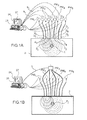
- the radiation source and the detection means may be respectively the end of an optical fiber which brings the excitation light into the medium and the end of an optical fiber which takes a part of the emission light.
- a set of sources Si (each of the sources, for example a laser source L i , is here connected to a fiber, so one assimilates the source at the end S i , the closest to the medium 2, of the fiber) bringing the light sequentially into the medium.
- a set of detection points is designated by D i : each of the detectors PM i is here connected to a fiber, so the detector is likened to the end, the closest to the medium 2, of the fiber. These detectors make it possible to sample the density of fluorescence photons.
- the number n s of sources can be any.
- the number n d of detectors can be any. For example, there may be a single detector, or 2 or 3, or any number n d > 3.
- the number n s of sources will be between 1 and 10.
- Each source L i may be a pulsed laser source or an optical fiber connected to a remote pulsed laser (which is the case of the configuration of the Figure 1A ).
- Each detector D i may comprise a set of camera pixels of the CCD or CMOS type, or comprise a photomultiplier, and it may be connected to an optical fiber which transmits the signal of the medium studied to the detector, which is the case of the configuration of Figures 1A and 1B .
- a temporal analysis of the signals is carried out using a dedicated measuring instrument (TCSPC Time Correlated Single Photon Counting - device for counting single photons correlated in time or intensified camera with a temporal door).
- TCSPC Time Correlated Single Photon Counting - device for counting single photons correlated in time or intensified camera with a temporal door.
- One of the sources of radiation pulses L i can also be used as a means triggering the TCSPC card (for example by a link 9 1 , 9 2 , 9 between each source L i and the means 24).
- pulses in the field of femto seconds it is preferable to work with pulses in the field of femto seconds, provided that the appropriate radiation source is available, ie one or more laser sources L i , each pulse of which has a width temporal also in the field of the second femto.
- the use of pulsed sources of the picosecond laser diode type is also conceivable, the advantage of such a solution being a lower cost.
- one or more sources L i is a pulsed laser diode, for example at a wavelength close to 630 nm and with a repetition rate of about 50 MHz.
- the laser light preferably passes through an interference filter to eliminate possible secondary modes.
- An interferential filter and / or a low wavelength absorbing color filter may be placed in front of each PM detector i or the end D i of the corresponding fiber to select the fluorescence light (for example: ⁇ > 650 nm, the source being at a wavelength of, for example, 631 nm) of a fluorophore F i disposed in the medium 2 and optimize the elimination of the excitation light.
- these positions are most often understood as those of the ends of the fibers which bring the radiation into the diffusing medium 2, or at the interface of this medium, and / or those which collect the scattered radiation, these The latter are placed in the middle or at the interface of this medium, but do not then agree to be those of the source L i itself or the PM i detector itself.
- the fibers bringing the radiation into the medium may be called excitation fibers, and the fibers collecting the scattered radiation may be called emission fibers, or collection fibers.
- a fiber system is preferably used, the fibers being able for example to be integrated in an endo-rectal probe, at least one fiber transmitting the pulsed excitation light source to the zone to be examined.
- This pulsed light source may be external to the probe.
- At least one other fiber transmits the optical transmission signal of the area to be examined to a photodetector, which may also be external to the probe.
- a photodetector which may also be external to the probe.
- TCSPC Time Correlated Single Photon Counting
- the system therefore allows time-resolved detection of the fluorescence pulses.
- t i represents the time elapsed between each laser pulse I i and the detection time of each photon p i .
- Such a curve M sd (t) which, as we see (see also the example of the figure 1E ), makes it possible to use all the information over a large time window, on either side of the point of maximum intensity (and not only in the rising part of the signal) can then be processed to derive characteristic information , such as arrival time, or average time as will be explained below.
- Electronic means 24 such as a microcomputer or a computer are programmed to store and process the data from the detectors. More specifically, a central unit 26 is programmed to implement a processing method according to the invention: calculating one or more parameters ⁇ N i, m or ⁇ 3, m or one or more functions of these parameters and / or applying a method as for example described below in connection with one of the figures 7 or 8 . These means 26 may optionally provide one or more comparisons of the value or values found for the parameter or parameters, with one or more threshold values.
- An operator selects one or more of these parameters and / or one or more functions of these parameters, and calculates them to obtain first information on a location of at least one fluorophore, possibly after comparing the results of the calculation with a or threshold values or at one or more minimum values or at one or more maximum values.
- the electronic means 24 may optionally control the triggering of the radiation sources and / or the detector or detectors, for example a synchronization of all these means.
- a screen or means 27 display or visualization allow, after treatment, to represent the positioning of the fluorophore or fluorophores in the medium 2 examined.
- the means 24 and the display means 27 also allow an operator to determine a mesh as used in the present application, as explained below.
- At least one other parameter may be selected, or at least one iteration may be performed.
- Other detection techniques may be employed, for example with an intensified camera, and for example a high-speed intensified camera of the "gated camera” type; in this case the camera opens on a time gate, of width for example about 200 ps, then this door is shifted, for example 25 ps in 25 ps.
- the excitation light at the wavelength ⁇ x excites the fluorophores F i which re-emits a so-called emission light at the wavelength ⁇ m > ⁇ x with a lifetime ⁇ .
- This lifetime corresponds to the average duration during which the excited electrons remain in this state before returning to their initial state.
- the method makes it possible to locate absorbers in the medium, that is to say places in which the absorption coefficient of the medium is higher than the average absorption coefficient of the medium.
- the surrounding medium 2 fluorophore F 1 can have any form of geometry: for example, it is of infinite type.
- the excitation and emission optical fibers can be placed at the interface of the scattering medium, or at shallow depth, of the order of a few mm.
- a semi-infinite medium for which each of the fiber ends of the excitation signal and the fluorescence signal collection signal is disposed more than 1 cm, or 1.5 cm or 2 cm from the limiting wall.
- this medium can be treated, from the point of view of the process according to the invention, as an infinite medium.
- the surrounding medium can still form a slice (geometry called "slab"), limited by two parallel surfaces.
- the invention also applies to a medium of any shape, the outer surface of which is decomposed into a series of plane facets.
- Green G s (r, t) of a device according to the invention can be determined using a Monte-Carlo simulation, for example to solve the radiative transfer equation or, most often, by solving the diffusion equation (1) to which boundary conditions are added (partial current condition (Robin) or extrapolated edge condition (Dirichlet)), as explained in the article of SR ARRIDGE: "Optical tomography in medical imaging", Inverse Problems, April 1999, vol 15 (2), R41-R93 .
- These determinations or simulations can be performed using computer means, such as means 26, 27 of Figures 1A and 1B .
- the moments of the functions of Green Gs (r, t), as previously defined (1 ') can be obtained by solving iteratively equation (2).
- a fluorophore is a single fluorophore F 1 , or a plurality of fluorophores grouped substantially in one place.
- the fluorophore consists of N fluorophores distributed in different places.
- the fluorescence map is reconstructed by a method that is effective from a computer point of view, and that has the property of concentrating the fluorescence on small supports.
- small supports represents the fact that the fluorophore or fluorophores are distributed discretely in certain places of the medium studied. Indeed, the inventors considered that this type of a priori applied well to the reconstruction of fluorophores in diffusing tissues, especially in certain applications related to the early detection of cancerous tumors in organs, such as the prostate, the breast , the testicles, the brain ...
- the information on M 0 sd and M 1 sd (already defined above, see for example equations 11-14) is used to reconstruct the position of the fluorophores, which emit the fluorescence radiation.
- the search volume of the fluorophore is meshed into M (or voxels) m, the size of which depends on the desired precision: the higher the precision, the more the individual volume a mesh is weak and the number of meshes is high.
- This mesh can be decided by an operator of the computer system 24.
- the index m denotes a voxel.
- each of these basic parameters depends on the variable m, thus on the mesh selected in the volume.
- the parameter which is a sum of contributions of all possible couples (source, detector) of the system or of a part of all these couples.
- each parameter represents the sum, for different acquisitions, each acquisition corresponding to a source-detector pair, of a combination between a quantity (here and in the rest of the text, this expression is equivalent to "function” or "quantity”).
- parameter established from at least one moment of M sd (t), and the estimation of this magnitude, this estimate being made by considering a single fluorophore positioned in the voxel m.
- the magnitude established from at least one moment of the function M sd (t) may be the moment of order 0 of this function, or else the normed moment of order 1, at which we subtract temporal quantities (or functions) known and assumed to be constant.
- this magnitude may be the moment of order 0 of M sd (t), denoted by M (0) sd .
- ⁇ 1m min ⁇ m ⁇ sd M sd 0 - ⁇ m .
- BOY WUT sm BOY WUT md 2 ⁇ 2 M sd 0
- ⁇ 1m can be considered as a residual between the measurement of the moment M (0) sd , and its estimate, given by the product ⁇ m G sm G md .
- ⁇ 1m is minimal for meshes m giving the best positioning of the fluorophore. Its value results from the calculation of the minimum value of the sum indicated above, for a set of coefficients ⁇ m . In other words, we search for the set of coefficients ⁇ m which minimizes the sum above.
- the quantity established from at least one moment of M sd (t) is the normalized moment of order 1, denoted T sd , to which is subtracted the time of the function the source Ts, the response time of the detector Td, as well as the fluorescence time ⁇ .
- T sd the normalized moment of order 1
- ⁇ 2m also called the residue criterion of flight time measurements, is also small for meshes satisfying a good temporal agreement, and thus contributing to give a better positioning of the fluorophore. More specifically, ⁇ 2m corresponds to a difference (or a residual) between, for at least one acquisition, the average measured detector source flight time (normalized moment of order 1 of M (t)) and this same order moment 1 normed modeled, the fluorophore then being supposed to correspond to the voxel m.
- Tsd - Ts - Td - ⁇ represents the "net" flight time, ie the measured flight time, to which the mean times of the source function, the detector response and the mean time are subtracted. the fluorescence lifetime. This net flight time represents the duration of the path of light between the source, the fluorophore and the detector.
- Tsm + Tdm represents an estimate of this net flight time when the fluorophore is present in the voxel m.
- T s , T d , ⁇ are in principle known data: ⁇ depends on the fluorophore, while the sum T s + T d can be obtained by a calibration test, as previously described.
- T sm and T dm are modeled, either analytically or by solving equation (2), considering that the fluorophore is unique and located in the voxel m.
- ⁇ 1m As for the first basic parameter ⁇ 1m , ⁇ 2m , is minimal for the meshes m in which the fluorophore is actually positioned.
- the inventors have highlighted the particular interest in jointly using these two basic parameters ⁇ 1m and ⁇ 2m .
- the first basic parameter ⁇ 1m gives a particularly relevant information as to the coordinates of the fluorophore in this plane.
- the voxels m for which the coefficient ⁇ 1m is minimum are generally distributed in the direction perpendicular to this plane, but their coordinates in this plane are little dispersed.
- the second basic parameter ⁇ 2m gives a particularly relevant information on the position of the fluorophore in the direction perpendicular to this plane.
- a parameter ⁇ 2m combining a measurement and an estimation of the flight time, gives an indication relative to the depth of the fluorophore with respect to a plane formed by the sources and detectors.
- the voxels m for which the coefficient ⁇ 2m is minimum are generally distributed substantially parallel to the plane formed by the sources and the detectors, and their coordinates in the direction perpendicular to this plane are little dispersed. These voxels are then located at the same depth relative to the location where the sources and detectors are located.
- the probability of the presence of the fluorophore in a voxel m will be all the higher as for this voxel, the first basic parameter ⁇ 1m and the second basic parameter ⁇ 2m are minimum. Due to the complementarity existing between these two first basic parameters ⁇ 1m and ⁇ 2m , one will obtain a relevant information as for the coordinates of the fluorophore in the plane defined by the sources and the detectors (by the first basic parameter ⁇ 1m ), but also information relevant to the coordinates of the fluorophore in the direction orthogonal to this plane, that is to say to the depth (by the second basic parameter ⁇ 2m ). The coordinates of the voxel likely to contain the fluorophore will thus be defined.
- a third basic parameter ⁇ 3m can be constituted by considering that the magnitude established from the distribution Msd (t) is the moment of order 0, as well as during the determination of the first basic parameter. This magnitude is then combined with the estimate of this quantity, said estimate being made considering that the fluorophore is unique and located in the voxel m. But this combination is not a difference here, but a correlation, in other words, a product.
- BOY WUT dm 2 m being the index corresponding to the voxel considered, s and d represent the source and the detector considered.
- ⁇ 3m is maximal for meshes m giving the best positioning of the fluorophore, especially in a plane substantially parallel to that formed by the sources and the detectors.
- Pm can be called a combined parameter, resulting from a combination of at least a first parameter (for a single parameter, we would rather speak of a "function" of this parameter, but we use in the present application, for example, simplification, the general term "combination").
- Such a combination Pm is also a function of m, that is to say the voxel considered.
- Such a combination P m of these parameters may be, according to a preferred mode, the sum of the first and second basic parameters: ⁇ 1 ⁇ m + ⁇ 2 ⁇ m
- Another example of a combination of the basic parameters can be for example the product of the first and second parameters: ⁇ 1 ⁇ m • ⁇ 2 ⁇ m
- Yet another example of a combination of the basic parameters can be for example the ratio of the third and the second basic parameters: ⁇ 3 ⁇ m / ⁇ 2 ⁇ m
- This combined parameter P m is maximum for the mesh (es) in which the fluorophore is most likely located, since the third parameter is then minimum, while the second is maximum.
- At least two of the basic parameters at least one of which is the argument of a non-linear function.
- the product ⁇ 1m 2 . ⁇ 2m the product of the square of the first by the second.
- Another example is the ratio ⁇ 2m 2 / ⁇ 3m .
- each value of the basic parameter or the combined parameter retained, for a given voxel can be stored in a vector X (M, 1), each coordinate of the vector representing the value P m of voxel m (1 ⁇ i ⁇ m).
- a vector may be called a fluorescence map.
- P limit is equal to at least half of the maximum value taken by this parameter on all the voxels under consideration and, for the case of a single fluorophore, it is possible, for example, to retain the voxel for which the parameter has the minimum value.
- the parameter chosen to take for a given voxel m 0 can appear on an image representative of the medium in question, for example on the screen 27, with a certain shade of color depending on the value of P m0 .
- the parameter ⁇ 3m / ⁇ 2m is used , equal to the ratio of the third to the second.
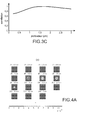
- Illumination is performed with the 9 sources and there is formation of a fluorescence signal by the 9 detectors.
- figure 3C is represented the value of ⁇ 3m as a function of the depth, along a vertical line (parallel to z) and passing through the fluorophore.
- the criterion map - ⁇ 2m is represented in Figures 4A and 4B . More precisely, it is the criterion max (- ⁇ 2m ) / 6- ⁇ 2m which is actually represented, limited to the positive values.
- Figure 4A are represented cuts of the Figure 4B at different altitudes of z.
- N (> 1) fluorophores is treated, where N is a known number.
- a medium 2 contains 2 fluorophores F 1 , F 2 and is provided with two sources S 1 , S 2 and 2 detectors D 1 , D 2 to detect the fluorescence emitted by the fluorophores.
- the signal of each of the two detectors contains a contribution of each of the two fluorophores.
- the moment values M (0) sd and M (1) sd for each pair will be replaced by a corrected value M ' (0) sd and M ' (1) sd, which takes into account the contributions of previously identified fluorophores.
- the corrected values are equal to the difference between the measured moments and the estimated contribution, at these times, of fluorophores already identified or localized. This is done by iteration.
- an X (M, N) matrix is reconstructed, N being the number of fluorophores, M being the number of voxels.
- Each element of the matrix X mn represents the combined coefficient P m corresponding to the voxel m (1 ⁇ m ⁇ M) and the fluorophore n (1 ⁇ n N N).
- This matrix is a association of N column vectors X (M, 1), that is to say N fluorescence maps.
- the measurements M sd (t) corresponding to different source-detector pairs are performed beforehand, which makes it possible to determine the moments M (0) sd and M (1) sd for each detector source pair.
- N number of fluorophores present a priori in the diffusing medium
- M number of voxels discretizing the medium
- G sm and G md are the simulated Green functions (of which we have already mentioned previously) and X mn is the element (m, n) of the matrix X, previously initialized to 0, but including terms already estimated when n>1; we force, M ' (0) sd and M' (1) sd to be strictly positive, by setting 0 strictly negative values (step S3) .S (0) and D (0) have already been defined.
- Each value of M ' (0) sd is the difference between the measured value of M (0) sd and the value estimated using the values G sm and G md , applied to the current coefficient X mn , such that results from the previous iteration (possibly from initial zeroing).
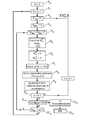
- step S4 determine, for each voxel m and using M ' (0) sd and M' (1) sd , at least one of the basic parameters ⁇ im (for example ⁇ 1m , ⁇ 2m , ⁇ 3m ) and optionally at least one combined parameter P m , P m having the form already defined previously for the case of a single fluorophore.
- ⁇ im for example ⁇ 1m , ⁇ 2m , ⁇ 3m
- ⁇ 1m is determined by replacing M (0) sd by M ' (0) sd and ⁇ 2m is determined by replacing T sd by M' (1) sd / M ' (0) sd , while ⁇ 3m is determined replacing I sd with M ' (0) sd
- Convergence can be achieved by a method of least squares. This step significantly improves the quality of the results.
- the matrix X is adjusted by multiplying each term of a column n by the coefficient ⁇ n .
- these coefficients ⁇ n can be assimilated to intensities of the fluorescence signal.
- step S7 We then increment n (step S7) and return to step S1 (where all the elements of column n are initialized to 0). If there is no S6 convergence test step, we go from S5 to S7.
- the correlation may comprise, for example, a so-called residual error test with respect to the data, corresponding to establishing a difference between an estimated quantity and an actually measured quantity.
- the estimated size is: ⁇ m ⁇ not BOY WUT sm ⁇ X mn ⁇ BOY WUT md ⁇ ⁇ not for the measured quantity M sd 0 .
- the estimated size is: ⁇ m ⁇ not BOY WUT sm ⁇ X mn ⁇ BOY WUT md ts + tsm + tm + tmd + td ⁇ m ⁇ not BOY WUT sm ⁇ X mn ⁇ BOY WUT md ⁇ not for the measured quantity M sd 1 / M sd 0
- the selected line m corresponds to a voxel m, in which the fluorophore is probably or very probably located.
- Another embodiment deals with the case of N (> 1) fluorophores, where N is an unknown whole number.
- N the number of desired fluorophore
- step S'2 all the elements of the matrix are initialized to 0. Only M (number of voxels discretizing the medium) is known.
- N iter is then initialized, the number of iterations, to 0 (step S'3), then it is incremented to 1 (step S'4). During the initialization of N iter it was also possible to determine the maximum number of iterations that one wishes to realize.
- the number of fluorophores is equal to the current number N and the matrix X consists of the elements previously determined (step S'12).
- step S'11 If the correlation is not satisfactory, one looks at whether the number of iterations and the maximum number N iter previously fixed.
- step S'3 by incrementing N iter by one unit.
- the line m for which the parameter, basic or combined gives the minimum or maximum value, depending on the nature of this parameter: as already explained above, for each of the parameters ⁇ 1m , ⁇ 2m the maximum value will be taken, and for the parameter ⁇ 3m the minimum value; and these principles are applied to any combined parameter that results from these basic parameters.
- the selected line m corresponds to a voxel m, in which the fluorophore is probably or very probably located.
- the two fluorophores are designated F 1 and F 2 on the Figure 9A .
- the sources S and the detectors D are arranged on a cylindrical surface, as can be seen in this figure.
- Figures 10A - 10D show representations of M (0) exp (measure of M (0) , figure 10A ), M (1) exp (measure of M (1) , figure 10B ), M (0) is (calculation of M (0) , Figure 10C ), M (1) is (calculation of M (1) , FIG. 10D) . These figures show that the convergence of the estimates towards the measured data is not satisfactory.
- FIGS 10E - 10H show representations of M (0) exp (measure of M (0) , figure 10E ), M (1) exp (measure of M (1) , figure 10F ), M (0) is (calculation of M (0) , figure 10G ), M (1) is (calculation of M (1) , figure 10H ). These figures show that the convergence of estimates towards the measured data is then satisfactory.
- a fourth embodiment corresponds to a generalization of the first embodiment.
- it has been seen that it is possible to establish basic coefficients ⁇ im effecting a sum, for different acquisitions, each acquisition corresponding to a source-detector pair, of a combination between a magnitude established from at least a moment of M sd (t), and the estimate of this magnitude, this estimation being carried out in considering a single fluorophore positioned in voxel m.
- base coefficients ⁇ im similar to those described in the first embodiment are also determined, but when the base coefficients ⁇ im N are determined , a prior configuration is set up according to which has N fluorophores located in different N voxels.
- the index m then corresponds to a configuration, that is to say a particular distribution of these N fluorophores among the M voxels according to which the medium studied was discretized.
- N being a strictly positive natural integer
- ⁇ im N the combination of a quantity obtained from at least one moment of Msd (t) with an estimate of said magnitude, this estimate being made considering that the N fluorophores are distributed according to the M voxels of the medium in a given distribution, said distribution being indexed by the parameter m.
- each ith basic coefficient ⁇ im is obtained by considering a given distribution m of the N fluorophores in the M voxels. As recalled above, there are therefore M N possible distributions, corresponding to as many possible second coefficients possible. In other words, 1 ⁇ m ⁇ M N
- a configuration corresponding to N fluorophores distributed in the voxels m n , 1 n n N N is considered here.
- G smn (respectively G mnd ) represent 1 energy transfer functions between the source and voxel m n (respectively voxel m n and detector d).
- the coefficients ⁇ n which can be considered as intensities are obtained by the minimization operation, as well as ⁇ 1m .
- This first basic parameter ⁇ 1m N is minimum for the configurations m closest to the actual distribution of N fluorophores in the medium studied.
- M sd (1) / M sd (0) which can also be denoted T sd , to which the known temporal variables Ts (mean time of the source), Td (detector response time) and ⁇ (fluorescence duration) can be subtracted
- T sd mean time of the source
- Td detector response time
- ⁇ fluorescence duration
- m corresponds to N fluorophores distributed in the voxels m n , 1 ⁇ n ⁇ N.
- G smn (respectively G mnd ) represent the energy transfer functions between the source and the voxel m n (respectively the voxel m n and the detector d) .
- T theo sd ( ⁇ 1, ... ⁇ N) thus defined corresponds well an estimate of T sd - T s - T d - ⁇ .
- ⁇ 2m N is the difference (or a residual, and more generally a comparison, this comparison can also be made by a ratio) between, for at least one measurement, between a quantity constituted by the average flight time source- measured detector (normalized moment of order 1 of M (t)), preferably, but not necessarily, reduced by known temporal quantities (T s , T d , T), and this same quantity modeled with the aid of a contribution of the set of fluorophores distributed according to the configuration m, by means of the coefficients ⁇ ' i , each of which is assigned to a fluorophore and which represents the emission intensity of the fluorescence therewith.
- the ⁇ ' n are obtained by the minimization operation, as well as ⁇ 2m N.
- the latter also called the residue criterion of time of flight measurements, is also small for configurations m corresponding to the actual distribution of the N fluorophores in the medium.
- the parameter ⁇ 2m N can be normalized by a statistical quantity relating to the distribution of T sd .
- This statistical magnitude acts as a confidence indicator, as already explained above for ⁇ 2m .
- ⁇ 2 (T sd ) We have chosen here ⁇ 2 (T sd ), but another statistical quantity (for example standard deviation or variance) could be chosen, to indicate the confidence that one attributes to a distribution, but as we saw previously, the Normalization by the coefficient ⁇ 2 (T sd ) is preferred.
- ⁇ 4 ⁇ m NOT min ⁇ 1 , ... ⁇ NOT ⁇ ⁇ sd ⁇ M sd 0 - M sd , m theo 0 ⁇ 1 , ... ⁇ NOT 2 ⁇ 2 M sd 0 + ⁇ sd ⁇ T sd - T s - ⁇ - T d - T sd , m theo ⁇ 1 , ... ⁇ NOT 2 ⁇ 2 T sd with: M sd , m theo 0 ⁇ 1 , ...
- the invention is advantageously applicable to tumor localization in the case of the prostate, but can be applied to other organs, including testes, breast, brain ....
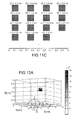
- the value of ⁇ is 0.95 ns.
- the graph of the Figure 11B shows that measurements based on the intensities alone (curve I) give unspecified results along z, whereas those based on the temporal results give precise results along z (curve II), which is confirmed by figure 11C .
- the value of ⁇ is 0.95 ns.
- the graph of the figure 12B shows that measurements based on the intensities alone (curve I ') give results without precision following z, while those based on the temporal results give precise results along z (curve II'), which confirms the figure 12C .
Landscapes
- Health & Medical Sciences (AREA)
- Physics & Mathematics (AREA)
- Life Sciences & Earth Sciences (AREA)
- General Physics & Mathematics (AREA)
- General Health & Medical Sciences (AREA)
- Pathology (AREA)
- Engineering & Computer Science (AREA)
- Immunology (AREA)
- Biochemistry (AREA)
- Theoretical Computer Science (AREA)
- Analytical Chemistry (AREA)
- Nuclear Medicine, Radiotherapy & Molecular Imaging (AREA)
- Chemical & Material Sciences (AREA)
- Medical Informatics (AREA)
- Public Health (AREA)
- Biomedical Technology (AREA)
- Heart & Thoracic Surgery (AREA)
- Mathematical Optimization (AREA)
- Molecular Biology (AREA)
- Surgery (AREA)
- Animal Behavior & Ethology (AREA)
- Algebra (AREA)
- Biophysics (AREA)
- Veterinary Medicine (AREA)
- Optics & Photonics (AREA)
- Radiology & Medical Imaging (AREA)
- Mathematical Analysis (AREA)
- Pure & Applied Mathematics (AREA)
- Mathematical Physics (AREA)
- Investigating, Analyzing Materials By Fluorescence Or Luminescence (AREA)
Abstract
Description
L'invention concerne le domaine de l'imagerie moléculaire de fluorescence sur les tissus biologiques par des méthodes optiques résolues en temps.The invention relates to the field of molecular fluorescence imaging on biological tissues by time-resolved optical methods.
Elle s'applique notamment à l'imagerie moléculaire optique sur le petit animal et à l'imagerie moléculaire optique sur l'homme (cerveau, sein, autres organes où des fluorophores peuvent être injectés).It applies in particular to optical molecular imaging in small animals and optical molecular imaging in humans (brain, breast, other organs where fluorophores can be injected).
L'application particulièrement visée est la détection de cancer de la prostate.The particularly targeted application is the detection of prostate cancer.
A l'heure actuelle, la localisation de cellules malades peut se faire à l'aide des techniques de biopsie.At present, the location of diseased cells can be done using biopsy techniques.
Mais, afin de trouver la position, même approximative, de ces cellules, on doit effectuer plusieurs prélèvements. Cette technique invasive est évidemment délicate à mettre en oeuvre et est consommatrice de temps.But, in order to find the position, even approximate, of these cells, one must make several samples. This invasive technique is obviously difficult to implement and is time consuming.
Il se pose donc le problème de la détermination de la localisation, même de manière approximative, de fluorophores fixés sur une zone d'un milieu, par exemple un milieu biologique.There is therefore the problem of determining the location, even approximately, of fluorophores fixed on an area of a medium, for example a biological medium.
Dans certains cas, on cherche même à localiser des fluorophore en vue d'une intervention chirurgicale ultérieure.In some cases, one even seeks to locate fluorophore for subsequent surgery.
Les techniques optiques d'imagerie moléculaire de fluorescence se développent donc de plus en plus actuellement grâce à l'utilisation de marqueurs fluorescents spécifiques. Ceux-ci viennent se fixer de façon préférentielle sur les cellules cibles d'intérêt (par exemple des cellules cancéreuses) et offrent un meilleur contraste de détection que les marqueurs non spécifiques. Ces techniques ont pour but de localiser spatialement la fluorescence mais aussi d'en déterminer la concentration.Fluorescence molecular imaging optical techniques are therefore developing more and more currently through the use of specific fluorescent markers. These are preferentially attached to the target cells of interest (for example cancer cells) and offer a better detection contrast than non-specific markers. These techniques are intended to spatially locate the fluorescence but also to determine the concentration.
Les systèmes de tomographie optique utilisent diverses sources de lumière. Il existe donc des appareils en mode continu, des appareils en mode fréquentiel (qui utilisent des lasers modulés en fréquence) et enfin des appareils fonctionnant en mode temporel, qui utilisent des sources lumineuses pulsées, ou sources lumineuses impulsionnelles, telles des Lasers pulsés.Optical tomography systems use a variety of light sources. There are therefore devices in continuous mode, frequency mode devices (which use frequency modulated lasers) and finally devices operating in time mode, which use pulsed light sources, or pulsed light sources, such as pulsed lasers.
Les données temporelles sont obtenues lorqu'on utilise une source de rayonnement impulsionnelle, ou source pulsée, délivrant un signal bref à une cadence déterminé. On parle alors d'imagerie diffuse résolue en temps. Les données temporelles sont celles qui contiennent le plus de contenu informationnel sur le tissu traversé, mais pour lesquelles les techniques de reconstruction sont les plus complexes. La mesure en chaque point d'acquisition est en effet une fonction dépendante du temps (appelée TPSF pour « Temporal Spread Function », ou fonction d'étalement temporel).The temporal data are obtained when using a source of pulsed radiation, or pulsed source, delivering a short signal at a determined rate. This is called diffuse imaging resolved in time. Time data is the one that contains the most informational content on the fabric that is traversed, but for which reconstruction techniques are the most complex. The measurement at each acquisition point is indeed a time dependent function (called TPSF for "Temporal Spread Function", or time spreading function).
On cherche à extraire des paramètres simples de la TPSF, dont on connaît par ailleurs l'expression théorique. Ensuite, la résolution du problème inverse permet de retrouver la distribution de fluorescence.It seeks to extract simple parameters of the TPSF, which is also known theoretical expression. Then, the resolution of the inverse problem makes it possible to find the fluorescence distribution.
On connaît des techniques de localisation, par exemple du document
Mais ces techniques ne donnent pas satisfaction, en particulier dans la géométrie dite en « rétrodiffusion » où sources et détecteurs sont d'un même coté de l'objet ou du milieu étudié.But these techniques are not satisfactory, especially in the so-called "backscattering" geometry where sources and detectors are on the same side of the object or environment studied.
Il est apparu aux inventeurs que, lors de l'application des techniques connues d'imagerie optique diffuse résolue en temps, un certain nombre de problèmes se posent. En effet, différentes répartitions de fluorophores peuvent aboutir à des mêmes mesures, une mesure étant par exemple l'intensité de fluorescence ou le temps de vol moyen, notamment en géométrie de réflexion.It has appeared to the inventors that, when applying known time-resolved diffuse optical imaging techniques, a number of problems arise. Indeed, different distributions of fluorophores can lead to the same measurements, a measurement being for example the fluorescence intensity or the average flight time, especially in reflection geometry.
Pour un milieu quelconque, connaissant ses propriétés optiques, on peut calculer la densité de photons pour une source de Dirac, ponctuelle et localisée en rs et à t=0s, à l'aide des fonctions de Green.For any medium, knowing its optical properties, we can calculate the photon density for a source of Dirac, punctual and localized in r s and at t = 0s, using the functions of Green.
Ces fonctions Gs(r,t) peuvent être déterminées en utilisant une simulation Monte-Carlo, ou en résolvant l'équation de transfert radiatif ou, le plus souvent, en résolvant l'équation de diffusion (1) auquel on ajoute des conditions de bord : 
Les moments de Gs, c'est-à-dire les quantité : 
suivent les équations différentielles données par (2) : 
Ainsi, Gs (0) est la solution de l'équation différentielle (2) avec seulement le Dirac comme terme source, et Gs (n) est la solution lorsque le terme source est proportionnel à Gs (n-1). La suite des fonctions Gs (n) se trouve donc par étapes successives.Thus, G s (0) is the solution of the differential equation (2) with only Dirac as source term, and G s (n) is the solution when the source term is proportional to G s (n-1) . The sequence of functions G s (n) is therefore in successive stages.
Dans le cas d'un milieu homogène infini, une solution analytique de (1) est connue. Il s'agit de : 
Les moments de cette fonction sont déterminés aussi analytiquement.The moments of this function are determined also analytically.
Les 2 premiers sont : 

Ces formules sont intéressantes pour simuler des mesures pour lesquelles on est capable d'insérer les sources (et détecteurs) dans le milieu (par exemple grâce à des fibres optiques au bout d'une aiguille de biopsie).These formulas are interesting to simulate measures for which one is able to insert the sources (and detectors) in the medium (for example, using optical fibers at the end of a biopsy needle).
Dans la suite de la demande, certains modes de réalisation feront appel aux moments 0 et 1 de la mesure Msd(t) provoquée par la source s et mesurée par le détecteur d.In the rest of the application, some embodiments will use the
Ils sont utiles car ils donnent l'énergie totale détectée Isd et le temps de vol Tsd.They are useful because they give the total detected energy I sd and the flight time T sd .
En effet : 
et 
and
La description de la chaîne des processus physiques est la suivante ; chaque photon est :
- émis par la source suivant une densité de probabilité décrite par la réponse temporelle de la source,
- puis se propage suivant la probabilité décrite par la fonction Gs(r,t) jusqu'à un point r du maillage,
- puis est absorbé suivant la concentration et la section efficace du fluorophore en r,
- puis est émis par le fluorophore à la longueur d'onde de fluorescence en r,
- puis se propage jusqu'au détecteur d suivant une probabilité Gd(r,t)
- et enfin est détecté par le détecteur, ce dernier ayant une réponse temporelle.
- emitted by the source according to a probability density described by the temporal response of the source,
- then propagates according to the probability described by the function G s (r, t) up to a point r of the mesh,
- then is absorbed according to the concentration and cross section of the fluorophore in r,
- then is emitted by the fluorophore at the fluorescence wavelength in r,
- then propagates to the detector d following a probability G d (r, t)
- and finally is detected by the detector, the latter having a time response.
Du fait des propriétés de retour inverse de la lumière, Gd(r,t) est la solution de (1) en remplaçant rs par rd (rd étant la position du détecteur considéré).Because of the inverse return properties of light, G d (r, t) is the solution of (1) by replacing r s by r d (r d being the position of the detector considered).
Au final, pour un fluorophore « Dirac » disposé en r, la mesure Msd effectuée par le détecteur d pour un milieu illuminé par la source s s'écrit : ![]()
![]()
Le signe * représente la convolution temporelle, F(t) est la réponse temporelle du fluorophore, S(t) est la fonction temporelle de la source et D(t) est la réponse temporelle du détecteur.The sign * represents the temporal convolution, F (t) is the temporal response of the fluorophore, S (t) is the temporal function of the source and D (t) is the temporal response of the detector.
En pratique, on est capable de déterminer le signal source détecté par le détecteur, ce qui permet d'aboutir à une convolution des réponses temporelles respectives de la source et du détecteur. Autrement dit, il n'est pas nécessaire d'estimer séparément la réponse temporelle de la source et la réponse temporelle du détecteur, c'est-à-dire la convolution S(t) * D(t).In practice, it is possible to determine the source signal detected by the detector, which leads to a convolution of the respective temporal responses of the source and the detector. In other words, it is not necessary to separately estimate the temporal response of the source and the time response of the detector, that is to say the convolution S (t) * D (t).
Ici, nous avons supposé que les fonctions temporelles des sources et des détecteurs sont indépendantes de leur position ; toutefois, si ce n'était pas le cas, on pourrait aisément traiter ce problème en écrivant Ss et Dd, les indices s et d étant les indices des différentes sources et des différents détecteurs.Here, we have assumed that the temporal functions of the sources and detectors are independent of their position; however, if this were not the case, we could easily treat this problem by writing S s and D d , the indices s and d being the indices of the different sources and the different detectors.
Pour une assemblée de fluorophores dans le volume Ω, nous obtenons : 
Du fait des propriétés de calcul des moments sur les produits de convolutions, nous obtenons pour les deux premiers moments de Msd(t) : 

En s'inspirant de (7) nous obtenons : 
Dans cette formule :
- Ts est le temps moyen de la fonction source,
- Ts (r) est le temps de vol moyen entre s et r,
- T(r) est le temps de vie τ du fluorophore, censé être invariant suivant la position,
- Td(r) est le temps de vol moyen entre r et le détecteur d,
- Td est le temps de réponse moyen du détecteur.
- T s is the average time of the source function,
- T s (r) is the average flight time between s and r,
- T (r) is the life time τ of the fluorophore, which is supposed to be invariant according to the position,
- T d (r) is the average flight time between r and detector d,
- T d is the average response time of the detector.
Dans le cas homogène infini, on voit d'après les formules (4) et (5) que Ts(r), temps de vol moyen entre s et r est juste égal à : 
Ainsi, ![]()
![]()
Dans le cas de la prostate, on obtient typiquement v=5cm/ns. De même pour Td(r).In the case of the prostate, typically v = 5cm / ns is obtained. Similarly for Td (r).
Lorsque le fluorophore est unique et ponctuel, les formules (10) et (12) se simplifient.When the fluorophore is unique and punctual, the formulas (10) and (12) are simplified.
Si le fluorophore se trouve à la position r0, les formules deviennent : ![]()
et 
![]()
and
s (0) D (0) et Ts + Td peuvent être mesurés au cours d'une opération de calibration, au cours de laquelle la source est placée face au détecteur. On obtient alors un signal de calibration, dont le moment d'ordre 0 est égal à S(0)D(0) et le moment normé d'ordre 1 est égal à Ts+Tds (0) D (0) and Ts + Td can be measured during a calibration operation, during which the source is placed facing the detector. We then obtain a calibration signal, whose order of
Ainsi, le temps de vol mesuré est égal au retard moyen de la source auquel s'ajoutent le temps de vol entre la source et le fluorophore, le temps de vie du fluorophore, le temps de vol entre le fluorophore et le détecteur et le temps de réponse du détecteur.Thus, the measured flight time is equal to the average delay of the source plus the flight time between the source and the fluorophore, the life time of the fluorophore, the flight time between the fluorophore and the detector and the time. detector response.
Passons maintenant au problème de la reconstruction de la fluorescence, d'abord dans le cas d'une assemblée de fluorophore. Or on constate que, en rétrodiffusion, la reconstruction des cartes de fluorescence dans un milieu diffus est très difficile.Turning now to the problem of fluorescence reconstruction, first in the case of a fluorophore assembly. However, it is found that, in backscattering, the reconstruction of the fluorescence maps in a diffuse medium is very difficult.
Les inventeurs ont constaté que, notamment en géométrie de réflexion, différentes configurations aboutissent à des mesures identiques. Ainsi, un fluorophore réparti de façon étendue peut produire une mesure équivalente à un flurophore ponctuel. Il apparaît donc que, lors de la reconstruction de fluorophores en réflexion, on a un fort besoin d'hypothèses a priori. Un type d'hypothèse que l'on peut utiliser est de dire que les fluorophores sont ponctuels et localisés en des lieux donné. Une telle hypothèse peut s'appeler une contrainte de support.The inventors have found that, in particular in reflection geometry, different configurations result in identical measures. Thus, an extended fluorophore can produce a measure equivalent to a point flurophore. It thus appears that, during the reconstruction of fluorophores in reflection, there is a strong need for hypotheses a priori. One type of hypothesis that can be used is to say that fluorophores are punctual and localized at given locations. Such an assumption can be called a support constraint.
Une première solution est de considérer que le fluorphore est unique et localisé de façon ponctuelle dans le milieu étudié.A first solution is to consider that the fluorphore is unique and localized punctually in the medium studied.
Une autre solution est de considérer une pluralité de fluophores ponctuels répartis dans le milieu étudié.Another solution is to consider a plurality of point fluophores distributed in the medium studied.
La formule (14) ci-dessus permet de reconstruire la fluorescence par « triangulation » , par exemple à l'aide de la technique décrite dans le document
En particulier, lorsque le milieu est homogène infini : ![]()
![]()
Ainsi, en combinant plusieurs couples source-détecteur, on peut remonter à la position r. L'inconvénient de cette méthode est qu'elle fournit autant de solutions qu'il y a de couples source-détecteur.Thus, by combining several source-detector pairs, it is possible to go back to the position r. The disadvantage of this method is that it provides as many solutions as there are source-detector pairs.
L'invention propose à cette fin un procédé de localisation d'au moins un fluorophore, dans un milieu diffusant à l'aide d'au moins une source de rayonnement pulsée apte à émettre un rayonnement d'excitation de ce fluorophore et d'au moins un détecteur apte à mesurer un signal de fluorescence émis par ce fluorophore comportant:
- l'éclairement du milieu par une source de rayonnement,
- la détection, par au moins un détecteur, du signal produit par le milieu à la longueur d'onde de fluorescence,
- pour au moins un couple source-détecteur, la réalisation d'une distribution temporelle Msd(t) du signal reçu par le détecteur,
- le milieu diffusant étant discrétisé en M voxels,
- the illumination of the medium by a source of radiation,
- detecting, by at least one detector, the signal produced by the medium at the fluorescence wavelength,
- for at least one source-detector pair, producing a time distribution M sd (t) of the signal received by the detector,
- the diffusing medium being discretized in M voxels,
Un tel procédé peut également comporter la détermination d'un paramètre combiné Pm N, combinant au moins un ou deux paramètres de base χN i,m.Such a method may also comprise the determination of a combined parameter P m N , combining at least one or two basic parameters χ N i, m .
Au moins un des paramètres de base peut être:
- un premier paramètre de base χN 1,m, qui est la somme, pour tous les couples (source, détecteur), des différences entre la valeur de l'intensité mesurée Msd 0 pour chaque couple (source, détecteur), et une estimation du moment d'ordre zéro, pour chaque couple (source, détecteur), obtenue à l'aide des fonctions de Green Gsmn et Gmnd, pour la source et le détecteur de chaque couple, cette estimation étant réalisée en considérant que les N fluorophores sont répartis dans les voxels du milieu selon la configuration m, selon laquelle les fluorophores sont répartis dans les voxels mn,
- ou un un second paramètre de base χN 2,m, qui est la somme, pour tous les couples (source, détecteur), des différences entre, pour chaque couple source -détecteur, le temps de vol moyen source-détecteur mesuré (moment normé d'ordre 1 de M(t)), corrigé de grandeurs temporelles connues relatives à la source, au détecteur et au fluorophore, et l'estimation de ce temps de vol corrigé, cette estimation étant réalisée en considérant que les N fluorophores sont répartis dans les voxels du milieu selon la configuration m.
- a first basic parameter χ N 1, m, which is the sum, for all the couples (source, detector), of the differences between the value of the measured intensity M sd 0 for each pair (source, detector), and a estimated zero order moment for each pair (source, detector), obtained using the functions of Green G smn and G mnd , for the source and the detector of each pair, this estimation being carried out considering that the N fluorophores are distributed in the voxels of the medium according to the configuration m, according to which the fluorophores are distributed in the voxels m n ,
- or a second basic parameter χ N 2, m, which is the sum, for all the couples (source, detector), of the differences between, for each source-detector pair, the measured mean time-source flight-detector (moment first order norm of M (t)), corrected with known temporal quantities relating to the source, the detector and the fluorophore, and the estimation of this corrected flight time, this estimation being carried out considering that the N fluorophores are distributed in the voxels of the medium according to the configuration m.
Par exemple, le coefficient de base χ1m N peut être tel que : 
avec : 
- une configuration m correspondant à N fluorophores répartis dans les voxels mn, 1≤n≤N,
- Gsmn (respectivement Gmnd) représentant les fonctions de transfert d'énergie entre la source et le voxel mn (respectivement le voxel mn et le détecteur d). Les coefficients αn, qui peuvent être considérés comme des intensités, sont obtenus, par l'opération de minimisation, de même que χ1m;
- chaque élément (Msd0 - Msd theo0 ,m(α1,... αN)) de la somme représentant alors la différence entre :
- la valeur de l'intensité mesurée Msd 0 pour le couple (source, détecteur) sélectionné,
- et une estimation du moment Msd 0 d'ordre zéro, obtenue à l'aide d'une part des fonctions de Green Gsmn et Gmnd, , et d' autre part d'un ensemble de coefficients αn dont chacun est affecté à un fluorophore et qui représente l'intensité d'émission de la fluorescence par celui-ci.
with:
- a configuration m corresponding to N fluorophores distributed in the voxels m n , 1≤n≤N,
- G smn (respectively G mnd ) representing the energy transfer functions between the source and the voxel m n (respectively the voxel m n and the detector d). The coefficients α n , which can be considered as intensities are obtained by the minimization operation, as well as χ 1m ;
- each element (Msd 0 - M sd theo0 , m (α 1, ... α N )) of the sum then representing the difference between:
- the value of the measured intensity M sd 0 for the pair (source, detector) selected,
- and an estimate of the zero-order moment M sd 0 , obtained using the functions of Green G smn and G mnd , and a set of coefficients α n each of which is assigned. to a fluorophore and which represents the intensity of emission of the fluorescence by it.
Le deuxième paramètre de base χ2m N peut être tel que : 
Avec : 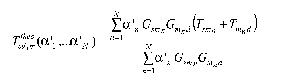
Ts, Td et T représentant respectivement les temps de réponse de la source, du détecteur et la durée de fluorescence du fluorophore, Tsmn et Tmnd représentant les temps de vol respectifs entre la source et le fluorophore localisé dans le voxel mn, et entre le fluorophore localisé dans le voxel mn et le détecteur, le coefficient σ2(Tsd) correspondant à une estimation de la variance de la distribution Tsd, Ttneo sd (α'1...α'N) représentant alors une estimation du moment normé d'ordre 1 de la fonction Msd(t), les coefficients α'N étant obtenus par l'opération de minimisation.Ts, Td and T respectively representing the response times of the source, the detector and the fluorescence duration of the fluorophore, Tsm n and Tm n d representing the respective flight times between the source and the fluorophore located in the voxel m n , and between the fluorophore located in the voxel m n and the detector, the coefficient σ 2 (Tsd) corresponding to an estimation of the variance of the distribution Tsd, T tneo sd (α'1 ... α'N) then representing an estimate of the normalized first order moment of the function M sd (t), the coefficients α ' N being obtained by the minimization operation.
Dans un tel procédé on peut également déterminer un paramètre combiné Pm N, égal à la somme ou au produit des coefficients de base χN 1,m, et χN 2,m, les paramètres combinés Pm N de plus faible valeur correspondant alors aux répartitions des fluorophores les plus proches de la répartition effective des fluorophores.In such a method it is also possible to determine a combined parameter P m N , equal to the sum or the product of the basic coefficients χ N 1, m, and χ N 2, m, the combined parameters P m N of lower value corresponding then the distributions of fluorophores closest to the effective distribution of fluorophores.
Le nombre de fluorophores peut être égal à 1, chaque paramètre de base χN=1 1,m, et χN=1 2,m, étant alors déterminé en considérant que le fluorophore est unique et localisé dans le voxel m. χN=1 1,m, et χ=1 2,m peuvent alors être déterminés selon les équations suivante : 
Et 
And
Msd 0 représentant le moment d'ordre 0 de la fonction Msd(t),
Gsm et Gmd étant des fonctions de transfert d'énergies entre, pour chaque couple source détecteur sd, respectivement la source s et le voxel m et entre le voxel m et le détecteur d,
Tsm et Tdm représentant les temps de vol respectifs entre la source et le voxel m et le voxel m et le détecteur d,
Ts, Td et τ représentant respectivement les temps de réponse de la source, du détecteur et la durée de fluorescence du fluorophore , le coefficient σ2(Tsd) corrspondant à une estimation de la variance de la distribution Tsd.M sd 0 representing the moment of
Gsm and Gmd being energy transfer functions between, for each detector source pair sd, respectively the source s and the voxel m and between the voxel m and the detector d,
Tsm and Tdm representing the respective flight times between the source and the voxel m and the voxel m and the detector d,
Ts, Td and τ respectively representing the response times of the source, the detector and the fluorescence duration of the fluorophore, the coefficient σ 2 (Tsd) corresponding to an estimation of the variance of the distribution Tsd.
Dans ce procédé on peut déterminer également un paramètre combiné Pm N, égal à la somme ou au produit des coefficients de base χN=1 1,m, et χN=1 2,m, les paramètres combinés Pm N=1 de plus faible valeur correspondant alors aux répartitions des fluorophores les plus proches de la répartition effective des fluorophores.In this method it is also possible to determine a combined parameter P m N , equal to the sum or the product of the basic coefficients χ N = 1 1, m, and χ N = 1 2, m, the combined parameters P m N = 1 lower value then corresponding to the distributions of fluorophores closest to the effective distribution of fluorophores.
L'invention propose également un procédé de localisation d'au moins un fluorophore ou d'au moins un absorbeur dans un milieu diffusant, à l'aide d'au moins une source de rayonnement impulsionnelle apte à émettre un rayonnement d'excitation de ce fluorophore ou de cette molécule et d'au moins un détecteur apte à mesurer un signal de fluorescence (Φfluo) émis par ce fluorophore ou un signal d'émission émis par cet absorbeur, comportant:
- a) pour au moins un couple (source de rayonnement, détecteur), au moins une excitation par un rayonnement provenant de la source de rayonnement de ce couple, et au moins une détection, par le détecteur de ce couple, du signal de fluorescence émis par ce fluorophore après cette excitation, ou du signal d'émission émis par cet absorbeur,
- b) l'identification d'un maillage (M) du volume en mailles élémentaires (m);
- c) une estimation de la localisation du fluorophore ou de l'absorbeur dans son milieu diffusant, par calcul d' une fonction (χ1m, χ'1m, χ2m, χ'2m, Pm) d'un au moins des trois paramètres suivants, pour chaque maille élémentaire du maillage :
- χ1m (ou χ1m N) qui est la somme, pour tous les couples (source, détecteur), des différences entre la valeur de l'intensité mesurée Msd 0 pour chaque couple (source, détecteur), éventuellement corrigée de l'estimation de la contribution à l'intensité, mesurée par le détecteur, de fluorophores déjà localisés, et une estimation du moment d'ordre zéro, pour chaque couple (source, détecteur), obtenue à l'aide des fonctions de Green Gsm et Gmd (ou Gsmn et Gmnd) pour la source et le détecteur de chaque couple et la maille élémentaire du maillage ;
- χ2m (ou χ2m N) qui est la somme, pour tous les couples (source, détecteur), des différences entre, pour chaque couple source -détecteur, le temps de vol moyen source-détecteur mesuré (moment normé d'ordre 1 de M(t)), éventuellement corrigé de l'estimation de la contribution, au temps de vol, de fluorophores déjà localisés, et ce même moment d'ordre 1 normé modélisé,
- χ3m qui est la somme, sur l'ensemble des couples source -détecteur, des corrélations entre, pour chaque couple source -détecteur, d'une part, une valeur de l'intensité mesurée (Isd = M(0)(t)) déterminée par le moment d'ordre 0 de M(t), noté M(0)(t), éventuellement corrigée de l'estimation de la contribution à l'intensité, mesurée par le détecteur, de fluorophores déjà localisés et, d'autre part, une valeur de ce moment d'ordre 0 modélisée à l'aide du produit Gsm.Gdm des fonctions de Green Gsm et Gmd, pour la source et le détecteur de chaque couple et la maille élémentaire du maillage.
- a) for at least one pair (radiation source, detector), at least one excitation by radiation from the radiation source of this pair, and at least one detection, by the detector of this pair, of the fluorescence signal emitted by this fluorophore after this excitation, or of the emission signal emitted by this absorber,
- b) identifying a mesh (M) of the elementary mesh volume (m);
- (c) an estimate of the location of the fluorophore or absorber in its diffusing medium, by calculating a function (χ 1m , χ ' 1m , χ 2m , χ' 2m, P m ) of at least one of the three following parameters, for each elementary mesh of the mesh:
- χ 1m (or χ 1m N ) which is the sum, for all the couples (source, detector), of the differences between the value of the measured intensity M sd 0 for each pair (source, detector), possibly corrected by the estimation of the contribution to the intensity, measured by the detector, of fluorophores already located, and an estimate of the zero-order moment, for each pair (source, detector), obtained using the functions of Green G sm and G md (or G smn and G mnd ) for the source and the detector of each pair and the elementary mesh of the mesh;
- χ 2m (or χ 2m N ), which is the sum, for all the couples (source, detector), of the differences between, for each source-detector pair, the measured mean source-detector flight time (standard time of
order 1 of M (t)), possibly corrected by the estimation of the contribution, at the time of flight, of fluorophores already localized, and this same modeled normalizedmoment 1, - χ 3m, which is the sum, over all the source-detector pairs, of the correlations between, for each source-detector pair, on the one hand, a value of the measured intensity (I sd = M (0) (t )) determined by the moment of
order 0 of M (t), denoted by M (0) (t), possibly corrected by the estimation of the contribution to the intensity, measured by the detector, of already localized fluorophores and, on the other hand, a value of this moment oforder 0 modelized using the product G sm .G dm of the functions of Green G sm and G md , for the source and the detector of each pair and the elementary mesh of the mesh.
χ1m N, χ2m N, χ3m peuvent avoir la forme déjà indiquée ci-dessus ou dans la suite de la présente demande.χ 1m N , χ 2m N , χ 3m may have the form already indicated above or in the remainder of this application.
Ladite fonction d'un au moins des trois paramètres peut être une fonction linéaire d'au moins un desdits paramètres et/ou une fonction non linéaire d'au moins un desdits paramètres.Said function of at least one of the three parameters may be a linear function of at least one of said parameters and / or a nonlinear function of at least one of said parameters.
Ainsi par exemple, un autre paramètre est χN 4,m : 
avec : 
et : 
with:
and
Un opérateur sélectionne un ou plusieurs de ces paramètres et/ou une ou plusieurs fonctions de ces paramètres, et le ou les calcule pour obtenir une première information sur une localisation d'au moins un fluorophore, éventuellement après avoir comparé les résultats du calcul à une ou des valeurs seuil ou à une ou des valeurs minimales ou à une ou des valeurs maximales.An operator selects one or more of these parameters and / or one or more functions of these parameters, and calculates them to obtain first information on a location of at least one fluorophore, possibly after comparing the results of the calculation with a or threshold values or at a or minimum values or at one or more maximum values.
Quel que soit le mode de réalisation de l'invention, on peut réaliser en outre, pour localiser plusieurs fluorophores, une étape d'ajustement, à l'intensité mesurée, de l'ensemble des contributions à l'intensité des fluorophores déjà localisés.Whatever the embodiment of the invention, it is also possible, in order to locate several fluorophores, a step of adjusting, at the measured intensity, all the contributions to the intensity of the fluorophores already located.
On peut en outre réaliser une étape de calcul d'une corrélation entre l'intensité mesurée et l'ensemble des contributions à l'intensité de l'ensemble des fluorophores.In addition, it is possible to perform a step of calculating a correlation between the measured intensity and the set of contributions to the intensity of all the fluorophores.
Dans le cas de plusieurs fluorophores de nombre inconnu, le procédé peut comporter en outre une étape (S'1) d'incrémentation du nombre de fluorophores si le calcul d'une corrélation n'est pas satisfaisant.In the case of several fluorophores of unknown number, the method may further comprise a step (S ' 1 ) of incrementing the number of fluorophores if the computation of a correlation is not satisfactory.
Le milieu environnant le fluorophore ou l'absorbeur peut être de type infini ou de type semi-infini ou en forme une tranche, limitée par deux surfaces parallèles, ou est de forme quelconque, sa surface extérieure étant discrétisée en une série de plans.The environment surrounding the fluorophore or the absorber may be of the infinite type or of the semi-infinite type or in the form of a wafer, bounded by two parallel surfaces, or of any shape, its outer surface being discretized into a series of planes.
Un procédé selon l'invention est particulièrement bien adapté au cas où les sources de rayonnement et les détecteurs sont en géométrie de réflexion.A method according to the invention is particularly well suited to the case where the radiation sources and the detectors are in reflection geometry.
L'invention concerne également un dispositif de localisation d'au moins un fluorophore, dans un milieu diffusant, comportant au moins une source de rayonnement pulsée apte à émettre un rayonnement d'excitation de ce fluorophore et au moins un détecteur apte à mesurer un signal de fluorescence émis par ce fluorophore comportant:
- des moyens pour réaliser, pour au moins un couple source-détecteur, une distribution temporelle Msd(t) du signal reçu par le détecteur,
- des moyens pour réaliser un maillage (M) du volume en mailles élémentaires m ;
- des moyens pour calculer au moins un paramètre de base χN i,m, combinant, pour au moins une desdites distributions temporelles Msd(t), au moins une grandeur obtenue à partir d'au moins un moment de ladite distribution, et au moins une estimation de cette grandeur, cette estimation étant réalisée en considérant qu'on dispose de N fluorophores, chacun occupant alors un voxel du milieu selon une répartition m.
- means for producing, for at least one source-detector pair, a time distribution M sd (t) of the signal received by the detector,
- means for making a mesh (M) of the elementary mesh volume m;
- means for calculating at least one basic parameter χ N i, m, combining, for at least one of said temporal distributions M sd (t), at least one quantity obtained from at least one moment of said distribution, and at least minus an estimate of this magnitude, this estimate being made considering that N fluorophores are available, each occupying then a voxel of the medium according to a distribution m.
Le coefficient de base χ1m N peut être tel que : 
avec : 
- une configuration m correspondant à N fluorophores répartis dans les voxels mn, 1≤n≤N,
- Gsmn (respectivement Gmnd) représentant les fonctions de transfert d'énergie entre la source et le voxel mn (respectivement le voxel mn et le détecteur d). Les coefficients αn, qui peuvent être considérés comme des intensités, sont obtenus, par l'opération de minimisation, de même que χ1m;
- Chaque élément (Msd 0 - Msd,m theo0 (α1,... αN)) de la somme représentant alors la différence entre :
- la valeur de l'intensité mesurée Msd 0 pour le couple (source, détecteur) sélectionné,
- et une estimation du moment Msd 0 d'ordre zéro, obtenue à l'aide d'une part des fonctions de Green Gsmn et Gmnd, , et d' autre part d'un ensemble de coefficients αn dont chacun est affecté à un fluorophore et qui représente l'intensité d'émission de la fluorescence par celui-ci.
with:
- a configuration m corresponding to N fluorophores distributed in the voxels m n , 1≤n≤N,
- G smn (respectively G mnd ) representing the energy transfer functions between the source and the voxel m n (respectively the voxel m n and the detector d). The coefficients α n , which can be considered as intensities, are obtained, by the minimization operation, as well as χ 1m ;
- Each element (M sd 0 - M sd, theo0 m (α 1, ... α N )) of the sum then representing the difference between:
- the value of the measured intensity M sd 0 for the pair (source, detector) selected,
- and an estimate of the zero-order moment M sd 0 , obtained using the functions of Green G smn and G mnd , and a set of coefficients α n each of which is assigned. to a fluorophore and which represents the intensity of emission of the fluorescence by it.
Le deuxième paramètre de base χ2m N peut être tel que : 
Avec : 
Ts, Td et T représentant respectivement les temps de réponse de la source, du détecteur et la durée de fluorescence du fluorophore, Tsmn et Tmnd représentant les temps de vol respectifs entre la source et le fluorophore localisé dans le voxel mn, et entre le fluorophore localisé dans le voxel mn et le détecteur, le coefficient σ2(Tsd) corrspondant à une estimation de la variance de la distribution Tsd, Ttheo sd,m (α'1...α'N) représentant alors une estimation du moment normé d'ordre 1 de la fonction Msd(t), les coefficients α' N étant obtenus par l'opération de minimisation.Ts, Td and T respectively representing the response times of the source, the detector and the fluorescence duration of the fluorophore, Tsm n and Tm n d representing the respective flight times between the source and the fluorophore located in the voxel m n , and between the fluorophore located in the voxel m n and the detector, the coefficient σ 2 (Tsd) corresponding to an estimate of the variance of the distribution Tsd, T theo sd, m (α'1 ... α'N) representing then an estimate of the normalized first order moment of the function M sd (t), the coefficients α ' N being obtained by the minimization operation.
Un tel dispositif peut comporter des moyens pour déterminer un paramètre combiné Pm N, égal à la somme ou au produit des coefficients de base χN 1,m, et χN 2,m. Les paramètres combinés Pm N=1 de plus faible valeur peuvent correspondre alors aux répartitions des fluorophores les plus proches de la réalité.Such a device may comprise means for determining a combined parameter P m N , equal to the sum or product of the basic coefficients χ N 1, m, and χ N 2, m. The combined parameters P m N = 1 of lower value can then correspond to the distributions of the fluorophores closest to reality.
Si le nombre de fluorophores est égal à 1, chaque paramètre de base χN=1 1,m, et χN=1 2,m, peut être déterminé en considérant que le fluorophore est unique est localisé dans le voxel m.If the number of fluorophores is equal to 1, each basic parameter χ N = 1 1, m, and χ N = 1 2, m, can be determined by considering that the fluorophore is unique is located in the voxel m.
χN=1 1,m, et χN=1 2,m peuvent être déterminés selon les équations suivante : 
Et 
And
Msd 0 représentant le moment d'ordre 0 de la fonction Msd(t),
Gsm et Gmd étant des fonctions de transfert d'énergies entre, pour chaque couple source détecteur sd, respectivement la source s et le voxel m et entre le voxel m et le détecteur d,
Tsm et Tdm représentant les temps de vol respectifs entre la source et le voxel m et le voxel m et le détecteur d,
Ts, Td et T représentant respectivement les temps de réponse de la source, du détecteur et la durée de fluorescence du fluorophore ,
le coefficient σ2(Tsd) corrspondant à une estimation de la variance de la distribution Tsd.M sd 0 representing the moment of
Gsm and Gmd being energy transfer functions between, for each detector source pair sd, respectively the source s and the voxel m and between the voxel m and the detector d,
Tsm and Tdm representing the respective flight times between the source and the voxel m and the voxel m and the detector d,
Ts, Td and T respectively representing the response times of the source, the detector and the fluorescence duration of the fluorophore,
the coefficient σ 2 (Tsd) corresponding to an estimation of the variance of the distribution Tsd.
L'invention concerne également un dispositif de localisation d'au moins un fluorophore ou d'au moins un absorbeur dans un milieu diffusant, comportant au moins une source de rayonnement apte à émettre un rayonnement d'excitation de ce fluorophore ou de cette molécule et au moins un détecteur apte à mesurer un signal de fluorescence Φfiuo) émis par ce fluorophore ou un signal d'émission émis par cet absorbeur, comportant:
- a) des moyens pour réaliser un maillage (M) du volume en mailles élémentaires m ;
- c) des moyens pour réaliser une estimation de la localisation du fluorophore ou de l'absorbeur dans son milieu diffusant, par calcul d'une fonction (Pm) d'un au moins de trois paramètres suivants :
- χ1m (ou χ1m N) qui est la somme, sur l'ensemble des couples source -détecteur, des différences entre la valeur de l'intensité mesurée Msd 0 pour chaque couple (source, détecteur) sélectionné, éventuellement corrigée de l'estimation de la contribution à l'intensité de fluorophores déjà localisés, et une estimation du moment d'ordre zéro obtenue à l'aide des fonctions de Green Gsm et Gmd (ou Gsmn et Gmnd),
- χ2m (ou χ2m N) qui est la somme, sur l'ensemble des couples source -détecteur, des différences entre, pour au moins une mesure, le temps de vol moyen source détecteur mesuré (moment normé d'ordre 1 de M(t)), éventuellement corrigée de l'estimation de la contribution au temps de vol de fluorophores déjà localisés, et ce même moment d'ordre 1 normé modélisé,
- χ3m qui est la somme, sur l'ensemble des couples source -détecteur, des corrélations entre, d'une part, une valeur de l'intensité mesurée (Isd = M(0)(t)) déterminée par le moment d'ordre 0 de M(t), noté M(0)(t), éventuellement corrigée de l'estimation de la contribution à l'intensité de fluorophores déjà localisés et, d'autre part, une valeur de ce moment d'ordre 0 modélisé (le produit Gsm.Gdm).
- a) means for producing a mesh (M) of the elementary mesh volume m;
- c) means for estimating the location of the fluorophore or absorber in its diffusing medium by calculating a function (P m ) of at least three of the following parameters:
- χ 1m (or χ 1m N ) which is the sum, over the set of source-detector pairs, of the differences between the measured intensity value M sd 0 for each selected pair (source, detector), possibly corrected by estimation of the contribution to the intensity of fluorophores already located, and an estimate of the order zero moment obtained using the functions of Green G sm and G md (or G s mn and G mnd ),
- χ 2m (or χ 2m N ) which is the sum, over all the source-detector pairs, of the differences between, for at least one measurement, the measured mean detector source flight time (M
standard order 1 momentum) (t)), possibly corrected for the estimated contribution to the flight time of fluorophores already located, and this same modeled normalizedmoment 1, - χ 3m, which is the sum, on all source-detector pairs, of the correlations between, on the one hand, a measured intensity value (I sd = M (0) (t)) determined by the moment of
order 0 of M (t), denoted by M (0) (t), possibly corrected by the estimation of the contribution to the intensity of fluorophores already located, and, on the other hand, a value of thisorder moment 0 modeled (the product G sm .G dm ).
Ladite fonction d'un au moins des trois paramètres peut être une fonction linéaire d'au moins un desdits paramètres et/ou une fonction non linéaire d'au moins un desdits paramètres.Said function of at least one of the three parameters may be a linear function of at least one of said parameters and / or a nonlinear function of at least one of said parameters.
Quel que soit son mode de réalisation un tel dispositif peut comporter des moyens pour réaliser, dans le cas d'une pluralité de fluorophores, une étape d'ajustement, à l'intensité mesurée, de l'ensemble des contributions à l'intensité des fluorophores déjà localisés.Whatever its embodiment, such a device may comprise means for producing, in the case of a plurality of fluorophores, a step of adjusting, at the measured intensity, all the contributions to the intensity of the fluorophores already located.
Il peut en outre comporter des moyens pour calculer une corrélation entre l'intensité mesurée et l'ensemble des contributions à l'intensité de l'ensemble des fluorophores.It may further comprise means for calculating a correlation between the measured intensity and the set of contributions to the intensity of all the fluorophores.
Des moyens peuvent être prévus pour incrémenter le nombre de fluorophores si le calcul d'une corrélation n'est pas satisfaisant.Means may be provided to increment the number of fluorophores if the calculation of a correlation is unsatisfactory.
Dans un tel dispositif les sources de rayonnement et les détecteurs sont de préférence en géométrie de réflexion.In such a device, the radiation sources and the detectors are preferably in reflection geometry.
-
Les
figures 1A-1B sont des schémas d'une configuration expérimentale de tomographie de fluorescence dans la géométrie de réflexion, pouvant être mise en oeuvre dans le cadre de l'invention.TheFigures 1A-1B are diagrams of an experimental configuration of fluorescence tomography in the reflection geometry, which can be implemented in the context of the invention. -
Les
figures 1C-1E représentent respectivement une série d'impulsions laser et de photons uniques émis, et une courbe de fluorescence obtenue à partir des données relatives aux photons uniques, ainsi que des courbes de fluorescence mesurées.TheFigures 1C-1E respectively represent a series of laser pulses and single emitted photons, and a fluorescence curve obtained from the single photon data, as well as measured fluorescence curves. -
La
figure 2 est un schéma d'une configuration de fluorophores, de sources et de détecteurs utilisée pour des tests.Thefigure 2 is a diagram of a configuration of fluorophores, sources and detectors used for testing. -
Les
Figures 3A-3C ,4A -4C illustrent l'application de critères non combinés, selon l'invention.TheFigures 3A-3C ,4A -4C illustrate the application of non-combined criteria, according to the invention. -
Les
Figures 5A-5B illustrent l'application d'un critère combiné, selon l'invention.TheFigures 5A-5B illustrate the application of a combined criterion, according to the invention. -
La
Figure 6 est un schéma d'une configuration de 2 fluorophores, de 2 sources et de 2 détecteurs.TheFigure 6 is a diagram of a configuration of 2 fluorophores, 2 sources and 2 detectors. -
Les
Figures 7 et8 sont des exemples de procédé selon l'invention.TheFigures 7 and8 are examples of the process according to the invention. -
Les
Figures 9A-9C et10A-10H illustrent des exemples d'application d'un procédé selon l'invention.TheFigures 9A-9C and10A-10H illustrate examples of application of a method according to the invention. -
Les
Figure 11A-11C et12A -12C illustrent des résultats obtenus avec un procédé selon l'invention.TheFigure 11A-11C and12A -12C illustrate results obtained with a method according to the invention.
Un dispositif expérimental dans une géométrie en réflexion (où les sources et détecteurs se trouvent sur la même face de l'objet ou du milieu étudié) est représenté en
La source de rayonnement et les moyens de détection peuvent être respectivement l'extrémité d'une fibre optique qui amène la lumière d'excitation dans le milieu et l'extrémité d'une fibre optique qui prélève une partie de la lumière d'émission.The radiation source and the detection means may be respectively the end of an optical fiber which brings the excitation light into the medium and the end of an optical fiber which takes a part of the emission light.
On y distingue le milieu diffusant 2 contenant des inclusions fluorescentes Fi (ici une inclusion F1 est représentée), un ensemble de sources Si (chacune des sources, par exemple une source laser Li, est ici reliée à une fibre, donc on assimile la source à l'extrémité Si, la plus proche du milieu 2, de la fibre) amenant la lumière séquentiellement dans le milieu.It distinguishes the diffusing
Un ensemble de points de détection est désigné par Di : chacun des détecteurs PMi est ici relié à une fibre, donc on assimile le détecteur à l'extrémité, la plus proche du milieu 2, de la fibre. Ces détecteurs permettent d'échantillonner la densité de photons de fluorescence.A set of detection points is designated by D i : each of the detectors PM i is here connected to a fiber, so the detector is likened to the end, the closest to the
D'une manière générale, le nombre ns de sources peut être quelconque. Il peut par exemple y avoir une seule source, ou 2 ou 3, ou tout nombre ns >3.In general, the number n s of sources can be any. For example, there may be a single source, or 2 or 3, or any number n s > 3.
Le nombre nd de détecteurs peut être quelconque. Il peut par exemple y avoir un seul détecteur, ou 2 ou 3, ou tout nombre nd >3.The number n d of detectors can be any. For example, there may be a single detector, or 2 or 3, or any number n d > 3.
De préférence, on a ns >2 ou >3 ou >5 et nd >2 ou >3 ou >5.Preferably, we have s > 2 or> 3 or> 5 and n d > 2 or> 3 or> 5.
Dans des applications ou une forte compacité est requise, en endoscopie par exemple, le nombre ns de sources sera compris entre 1 et 10.In applications where a high compactness is required, in endoscopy for example, the number n s of sources will be between 1 and 10.
Chaque source Li peut être une source laser impulsionnel ou une fibre optique reliée à un laser impulsionnel déporté (ce qui est le cas de la configuration de la
Chaque détecteur Di peut comporter un ensemble des pixels de caméras de type CCD ou CMOS, ou comporter un photomultiplicateur, et il peut être relié à une fibre optique qui transmet le signal du milieu étudié vers le détecteur, ce qui est le cas de la configuration des
Selon un mode de réalisation, en sortie du ou des détecteurs, on réalise une analyse temporelle des signaux à l'aide d'instrument de mesure dédié (TCSPC Time Correlated Single Photon Couting - dispositif de comptage de photons uniques correlés en temps ou caméra intensifiée avec une porte temporelle).According to one embodiment, at the output of the detector (s), a temporal analysis of the signals is carried out using a dedicated measuring instrument (TCSPC Time Correlated Single Photon Counting - device for counting single photons correlated in time or intensified camera with a temporal door).
L'une des sources d'impulsions de rayonnement Li peut également être utilisée comme moyen de déclenchement de la carte TCSPC (par exemple par une liaison 91, 92, 9 entre chaque source Li et les moyens 24) .One of the sources of radiation pulses L i can also be used as a means triggering the TCSPC card (for example by a
Il est préférable de travailler avec des impulsions dans le domaine de la femto seconde, à condition de disposer de la source de rayonnement adéquate, c'est-à-dire d'une ou de plusieurs sources laser Li dont chaque impulsion a une largeur temporelle également dans le domaine de la femto seconde. L'utilisation de sources pulsées du type diode Laser picoseconde est également envisageable, l'avantage d'une telle solution étant un moindre coût.It is preferable to work with pulses in the field of femto seconds, provided that the appropriate radiation source is available, ie one or more laser sources L i , each pulse of which has a width temporal also in the field of the second femto. The use of pulsed sources of the picosecond laser diode type is also conceivable, the advantage of such a solution being a lower cost.
Selon un mode particulier de réalisation, une ou plusieurs sources Li est une diode laser pulsée, par exemple à une longueur d'onde voisine de 630 nm et avec un taux de répétition d'environ 50 MHz.According to a particular embodiment, one or more sources L i is a pulsed laser diode, for example at a wavelength close to 630 nm and with a repetition rate of about 50 MHz.
La lumière Laser passe de préférence par un filtre interférentiel pour éliminer d'éventuels modes secondaires. Un filtre interférentiel et/ou un filtre coloré absorbant les faibles longueurs d'onde peuvent être placés devant chaque détecteur PMi ou l'extrémité Di de la fibre correspondante pour sélectionner la lumière de fluorescence (par exemple : λ > 650 nm, la source étant à une longueur d'onde de, par exemple, 631 nm) d'un fluorophore Fi disposé dans le milieu 2 et optimiser l'élimination de la lumière d'excitation.The laser light preferably passes through an interference filter to eliminate possible secondary modes. An interferential filter and / or a low wavelength absorbing color filter may be placed in front of each PM detector i or the end D i of the corresponding fiber to select the fluorescence light (for example: λ> 650 nm, the source being at a wavelength of, for example, 631 nm) of a fluorophore F i disposed in the
Dans le texte de la présente demande, quel que soit le mode de réalisation de l'invention, il sera notamment question de la position de la source de rayonnement, et/ou de la position des moyens de détection.In the text of the present application, whatever the embodiment of the invention, it will include question of the position of the radiation source, and / or the position of the detection means.
Lorsque des fibres sont utilisées, ces positions s'entendent le plus souvent comme celles des extrémités des fibres qui amènent le rayonnement dans le milieu diffusant 2, ou à l'interface de ce milieu, et /ou celles qui collectent le rayonnement diffusé, ces dernières étant placées dans le milieu ou à l'interface de ce milieu, mais ne s'entendent alors pas comme étant celles de la source Li proprement dite ou du détecteur PMi proprement dit. Les fibres amenant le rayonnement dans le milieu peuvent être appelées fibres d'excitation, et les fibres collectant le rayonnement diffusé peuvent être appelées fibres d'emission, ou fibres de collection.When fibers are used, these positions are most often understood as those of the ends of the fibers which bring the radiation into the diffusing
En application de type « endoscopie », on utilise préférentiellement un système à fibres, les fibres pouvant être par exemple intégrées dans une sonde endo-rectale, au moins une fibre transmettant la source de lumière pulsée d'excitation à la zone à examiner.In "endoscopic" type application, a fiber system is preferably used, the fibers being able for example to be integrated in an endo-rectal probe, at least one fiber transmitting the pulsed excitation light source to the zone to be examined.
Cette source de lumière pulsée peut être externe à la sonde.This pulsed light source may be external to the probe.
Au moins une autre fibre transmet le signal optique d'émission de la zone à examiner vers un photodétecteur, qui peut lui aussi être externe à la sonde. Selon la technique TCSPC (pour « Time Correlated Single Photon Counting », ou comptage de photons uniques correlés en temps) on détecte, à l'aide du photomultiplicateur, un photon émis par le fluorophore après une impulsion de la source de rayonnement.At least one other fiber transmits the optical transmission signal of the area to be examined to a photodetector, which may also be external to the probe. According to the TCSPC (Time Correlated Single Photon Counting) technique, a photon emitted by the fluorophore is detected by means of the photomultiplier after a pulse of the radiation source.
Le système permet donc une détection résolue en temps des impulsions de fluorescence.The system therefore allows time-resolved detection of the fluorescence pulses.
Il permet de récupérer des photons de fluorescence.It allows to recover fluorescence photons.
La
Chaque photon est en fait détecté par rapport au départ de l'impulsion correspondante : sur la
Il est donc ensuite possible d'établir une répartition statistique ou histogramme du temps d'arrivée des photons, comme illustré sur la
Une telle courbe Msd (t) qui, on le voit (voir également l'exemple de la
Des moyens électroniques 24 tels qu'un micro ordinateur ou un calculateur sont programmés pour mémoriser et traiter les données issues des détecteurs. Plus précisément une unité centrale 26 est programmée pour mettre en oeuvre un procédé de traitement selon l'invention : calculer un ou des paramètres χN i,m ou χ3,m ou une ou plusieurs fonctions de ces paramètres et/ou appliquer un procédé tel que par exemple décrit ci dessous en liaison avec l'une des
Un opérateur sélectionne un ou plusieurs de ces paramètres et/ou une ou plusieurs fonctions de ces paramètres, et le ou les calcule pour obtenir une première information sur une localisation d'au moins un fluorophore, éventuellement après avoir comparé les résultats du calcul à une ou des valeurs seuil ou à une ou des valeurs minimales ou à une ou des valeurs maximales.An operator selects one or more of these parameters and / or one or more functions of these parameters, and calculates them to obtain first information on a location of at least one fluorophore, possibly after comparing the results of the calculation with a or threshold values or at one or more minimum values or at one or more maximum values.
Les moyens électroniques 24 permettent éventuellement un contrôle du déclenchement de la ou des sources de rayonnement et/ou du ou des détecteurs, par exemple une synchronisation de l'ensemble de ces moyens.The electronic means 24 may optionally control the triggering of the radiation sources and / or the detector or detectors, for example a synchronization of all these means.
Un écran ou des moyens 27 d'affichage ou de visualisation permettent, après traitement, de représenter le positionnement du ou des fluorophores dans le milieu 2 examiné. Les moyens 24 et les moyens 27 d'affichage permettent également à un opérateur de déterminer un maillage tel qu'utilisé dans la présente demande, comme expliqué ci dessous.A screen or means 27 display or visualization allow, after treatment, to represent the positioning of the fluorophore or fluorophores in the medium 2 examined. The means 24 and the display means 27 also allow an operator to determine a mesh as used in the present application, as explained below.
Si le résultat d'une localisation ne convient ou n'est pas satisfaisant, par exemple par manque de précision, au moins un autre paramètre peut être sélectionné, ou au moins une itération peut être réalisée.If the result of a location is unsatisfactory or unsatisfactory, for example due to lack of precision, at least one other parameter may be selected, or at least one iteration may be performed.
D'autres techniques de détection peuvent être employées, par exemple avec une caméra intensifiée, et par exemple une caméra intensifiée ultra-rapide de type « gated camera » ; dans ce cas la caméra s'ouvre sur une porte temporelle, de largeur par exemple environ 200 ps, puis cette porte est décalée, par exemple de 25 ps en 25 ps.Other detection techniques may be employed, for example with an intensified camera, and for example a high-speed intensified camera of the "gated camera" type; in this case the camera opens on a time gate, of width for example about 200 ps, then this door is shifted, for example 25 ps in 25 ps.
La lumière d'excitation, à la longueur d'onde λx excite les fluorophores Fi qui réémet une lumière dite d'émission à la longueur d'onde λm > λx avec une durée de vie τ. Cette durée de vie correspond à la durée moyenne pendant laquelle les électrons excités restent dans cet état avant de retourner à leur état initial. Dans le cas ou l'on n'effectue pas d'imagerie de fluorescence, la méthode permet de localiser des absorbeurs dans le milieu, c'est-à-dire des lieux dans lesquels le coefficient d'absorption du milieu est plus élevé que le coefficient d'absorption moyen du milieu. Dans la suite de la demande, on pourra assimiler un tel absorbeur à un fluorophore, en considérant que sa longueur d'onde de fluorescence, ou longueur d'onde d'émission, égale à la longueur d'onde d'excitation, et en considérant également que la durée de fluorescence est nulle, soit T = 0. Dans un tel cas, le filtre éventuellement placé en amont du détecteur sera adapté à la longueur d'onde d'excitation.The excitation light at the wavelength λ x excites the fluorophores F i which re-emits a so-called emission light at the wavelength λ m > λ x with a lifetime τ. This lifetime corresponds to the average duration during which the excited electrons remain in this state before returning to their initial state. In the case where fluorescence imaging is not carried out, the method makes it possible to locate absorbers in the medium, that is to say places in which the absorption coefficient of the medium is higher than the average absorption coefficient of the medium. In the rest of the application, we can assimilate such an absorber to a fluorophore, considering that its fluorescence wavelength, or emission wavelength, equal to the excitation wavelength, and considering also that the fluorescence duration is zero, ie T = 0. In such a case, the filter possibly placed upstream of the detector will be adapted to the excitation wavelength.
Quels que soient le milieu considéré et la géométrie, une ou des inclusions fluorescentes sont situées dans celui-ci, qui présente une vitesse de propagation de la lumière c (=3*108m/s/n, n = indice optique), un coefficient de diffusion D et un coefficient d'absorptionWhatever the medium considered and the geometry, one or more fluorescent inclusions are located therein, which has a light propagation velocity c (= 3 * 10 8 m / s / n, n = optical index), a diffusion coefficient D and an absorption coefficient
Le milieu environnant 2 le fluorophore F1 peut avoir toute forme de géométrie : par exemple, il est de type infini.The surrounding
Il peut aussi être de type semi infini, limité par une paroi. Dans un tel cas, les fibres optiques d'excitation et d'émission peuvent être placées à l'interface du milieu diffusant, ou à faible profondeur, de l'ordre de quelques mm.It can also be semi-infinite type, limited by a wall. In such a case, the excitation and emission optical fibers can be placed at the interface of the scattering medium, or at shallow depth, of the order of a few mm.
Un milieu semi infini, pour lequel chacune des extrémités de fibres d'amenée du signal d'excitation et de prélèvement du signal de fluorescence est disposée à plus de 1 cm, ou de 1,5 cm ou de 2 cm de la paroi qui limite ce milieu peut être traité, du point de vue du procédé selon l'invention, comme un milieu infini.A semi-infinite medium, for which each of the fiber ends of the excitation signal and the fluorescence signal collection signal is disposed more than 1 cm, or 1.5 cm or 2 cm from the limiting wall. this medium can be treated, from the point of view of the process according to the invention, as an infinite medium.
Le milieu environnant peut encore former une tranche (géométrie dite « slab »), limitée par deux surface parallèles.The surrounding medium can still form a slice (geometry called "slab"), limited by two parallel surfaces.
L'invention s'applique aussi à un milieu de forme quelconque, dont la surface extérieure est décomposée en une série de facettes planes.The invention also applies to a medium of any shape, the outer surface of which is decomposed into a series of plane facets.
Dans tous les cas elle est particulièrement bien adaptée au cas où la géométrie est en réflexion, dans lequel la ou les sources et le ou les détecteurs se trouvent sur la même face de l'objet ou du milieu étudié).In all cases it is particularly well suited to the case where the geometry is in reflection, in which the source (s) and the detector (s) are on the same face of the object or environment studied).
Les fonctions de Green Gs(r,t) d'un dispositif selon l'invention peuvent être déterminées en utilisant une simulation Monte-Carlo, par exemple pour résoudre l'équation de transfert radiatif ou, le plus souvent, en résolvant l'équation de diffusion (1) auquel on ajoute des conditions de bords (condition de courant partiel (Robin) ou condition de bord extrapolé (Dirichlet)), comme expliqué dans l'article de
Selon un mode de réalisation de l'invention, un fluorophore est un fluorophore unique F1, ou une pluralité de fluorophores groupés sensiblement en un même lieu.According to one embodiment of the invention, a fluorophore is a single fluorophore F 1 , or a plurality of fluorophores grouped substantially in one place.
Selon un autre mode de réalisation, le fluorophore est constitué de N fluorophores répartis dans des lieux différents.According to another embodiment, the fluorophore consists of N fluorophores distributed in different places.
A l'aide de mesures optiques résolues en temps, on cherche à localiser ces inclusions fluorescentes, c'est-à-dire à reconstruire la carte de fluorescence.With the aid of time-resolved optical measurements, it is sought to locate these fluorescent inclusions, that is to say to reconstruct the fluorescence map.
Selon l'invention, on reconstruit la carte de fluorescence par une méthode efficace d'un point de vue informatique, et qui a la propriété de concentrer la fluorescence sur de petits supports. Le terme "petits supports" représente le fait que le ou les fluorophores sont répartis de façon discrète dans certains lieux du milieu étudié. En effet, les inventeurs ont considéré que ce type d'a priori s'appliquait bien à la reconstruction de fluorophores dans des tissus diffusants, notamment dans certaines applications liées à la détection précoce de tumeurs cancéreuses dans des organes, tels la prostate, le sein, les testicules, le cerveau...According to the invention, the fluorescence map is reconstructed by a method that is effective from a computer point of view, and that has the property of concentrating the fluorescence on small supports. The term "small supports" represents the fact that the fluorophore or fluorophores are distributed discretely in certain places of the medium studied. Indeed, the inventors considered that this type of a priori applied well to the reconstruction of fluorophores in diffusing tissues, especially in certain applications related to the early detection of cancerous tumors in organs, such as the prostate, the breast , the testicles, the brain ...
Dans un 1er mode de réalisation, on considère le cas d'un fluorophore unique.In a 1 st embodiment, consider the case of a single fluorophore.
Selon le procédé utilisé, on met en oeuvre les informations sur M0 sd et M1 sd (déjà définis ci-dessus, voir par exemple équations 11-14) afin de reconstruire la position des fluorophores, lesquels émettent le rayonnement de fluorescence.According to the method used, the information on M 0 sd and M 1 sd (already defined above, see for example equations 11-14) is used to reconstruct the position of the fluorophores, which emit the fluorescence radiation.
Dans tous les cas, on maille le volume de recherche du fluorophore en M mailles (ou voxels) m, dont la taille dépend de la précision souhaitée : plus la précision est élevée, plus le volume individuel d'une maille est faible et plus le nombre de mailles est élevé.In all cases, the search volume of the fluorophore is meshed into M (or voxels) m, the size of which depends on the desired precision: the higher the precision, the more the individual volume a mesh is weak and the number of meshes is high.
Ce maillage peut être décidé par un opérateur du système informatique 24.This mesh can be decided by an operator of the
Selon l'invention, on utilise un ou plusieurs premiers χim paramètres dits paramètres de base(ou critères, mais on utilisera par la suite de l'expression « paramètres ») qui sont définis ci-dessous, ou une combinaison de ceux-ci, cette combinaison pouvant être alors appelé paramètre combiné Pm. Selon ce mode de réalisation, l'indice m désigne un voxel.According to the invention, one or more first parameters χ im so called basic parameters (or criteria, but later we will use the term "parameters") which are defined below, or a combination thereof this combination can then be called the combined parameter Pm. According to this embodiment, the index m denotes a voxel.
Chacun de ces paramètres de base dépend de la variable m, donc de la maille sélectionnée dans le volume. On sélectionne une à une toutes les mailles, et pour chaque maille, on calcule le paramètre, qui est une somme de contributions de tous les couples (source, détecteur) possibles du système ou d'une partie de l'ensemble de ces couples. Autrement dit, chaque paramètre représente la somme, pour différentes acquisitions, chaque acquisition correpondant à un couple source-détecteur, d'une combinaison entre une grandeur (ici et dans la suite du texte, cette expression est équivalente à « fonction » ou « quantité » ou « paramètre ») établie à partir d'au moins un moment de Msd(t), et l'estimation de cette grandeur, cette estimation étant réalisée en considérant un fluorophore unique positionné dans le voxel m.Each of these basic parameters depends on the variable m, thus on the mesh selected in the volume. We select one by one all the meshes, and for each mesh, we calculate the parameter, which is a sum of contributions of all possible couples (source, detector) of the system or of a part of all these couples. In other words, each parameter represents the sum, for different acquisitions, each acquisition corresponding to a source-detector pair, of a combination between a quantity (here and in the rest of the text, this expression is equivalent to "function" or "quantity"). Or "parameter") established from at least one moment of M sd (t), and the estimation of this magnitude, this estimate being made by considering a single fluorophore positioned in the voxel m.
Par combinaison, on entend toute opération arithmétique, linéaire ou non. On verra dans la suite de la description que cette combinaison peut prendre par exemple la forme d'une soustraction ou d'un produit.By combination, we mean any arithmetic operation, linear or not. We will see later from the description that this combination can take for example the form of a subtraction or a product.
On verra également que la grandeur établie à partir d'au moins un moment de la fonction Msd(t) peut-être le moment d'ordre 0 de cette fonction, ou encore le moment normé d'ordre 1, auquel on soustrait des grandeurs (ou fonctions) temporelles connues et supposées constantes.It will also be seen that the magnitude established from at least one moment of the function M sd (t) may be the moment of
Selon un mode préféré, cette grandeur peut-être le moment d'ordre 0 de Msd(t), noté M(0) sd.According to a preferred mode, this magnitude may be the moment of
Ainsi on définit un premier paramètre de base , χ1m: 
χ1m, peut être considéré comme un résidu entre la mesure du moment M(0) sd, et son estimation, donnée par le produit αmGsmGmd. χ1m est minimal pour les mailles m donnant le meilleur positionnement du fluorophore. Sa valeur résulte du calcul de la valeur minimum de la somme indiquée ci-dessus, pour un ensemble de coefficients αm. Autrement dit, on recherche l'ensemble des coefficients αm qui minimise la somme ci-dessus.χ 1m , can be considered as a residual between the measurement of the moment M (0) sd , and its estimate, given by the product α m G sm G md . χ 1m is minimal for meshes m giving the best positioning of the fluorophore. Its value results from the calculation of the minimum value of the sum indicated above, for a set of coefficients α m . In other words, we search for the set of coefficients α m which minimizes the sum above.
Le terme σ2(Msd 0) figurant au dénominateur est optionnel. Il s'agit d'une estimation de l'incertitude associée à la détermination de Msd 0. Si Msd 0 est le nombre de photons détecté par le couple de détecteurs (s, d), et si le bruit est Poissonien, alors σ2(Msd 0) = Msd 0 The term σ 2 ( M sd 0 ) in the denominator is optional. This is an estimate of the uncertainty associated with the determination of M sd 0 . If M sd 0 is the number of photons detected by the pair of detectors (s, d), and if the noise is Poissonian, then σ 2 ( M sd 0 ) = M sd 0
Ainsi, chaque élément (Msd 0 - αmGsmGmd)2 de la somme représente la différence entre :
- la valeur de l'intensité mesurée Msd 0 pour le couple (source, détecteur) sélectionné, lorsque la source émet une impulsion et le détecteur détecte un signal de fluorescence émis par le fluorophore,
- et une estimation du moment Msd 0 d'ordre zéro, obtenue à l'aide des fonctions de Green Gsm et Gmd, qui peuvent être estimées de la manière déjà décrite ci-dessus, par exemple à l'aide des moyens 24.
- the value of the measured intensity M sd 0 for the pair (source, detector) selected, when the source emits a pulse and the detector detects a fluorescence signal emitted by the fluorophore,
- and an estimate of the zero-order moment M sd 0 , obtained using the functions of Green G sm and G md , which can be estimated in the manner already described above, for example using the
means 24 .
Toujours selon un mode préféré de réalisation, la grandeur établie à partir d'au moins un moment de Msd(t) est le moment normé d'ordre 1, noté Tsd, auquel on retranche le temps de la fonction la source Ts, le temps de réponse du détecteur Td, ainsi que le temps de fluorescence τ. On utilise dans ce cas un deuxième paramètre de base, χ2m : 
χ2m, appelé aussi critère de résidu des mesures de temps de vol, est lui aussi petit pour des mailles vérifiant un bon accord temporel, et donc contribuant à donner un meilleur positionnement du fluorophore. Plus spécifiquement, χ2m correspond à une différence (ou un résidu) entre, pour au moins une acquisition, le temps de vol moyen source détecteur mesuré (moment normé d'ordre 1 de M(t)) et ce même moment d'ordre 1 normé modélisé, le fluorophore étant alors supposé correspondre au voxel m.χ 2m , also called the residue criterion of flight time measurements, is also small for meshes satisfying a good temporal agreement, and thus contributing to give a better positioning of the fluorophore. More specifically, χ 2m corresponds to a difference (or a residual) between, for at least one acquisition, the average measured detector source flight time (normalized moment of
Dans l'expression ci-dessus de ce paramètre χ2m:
- Tsd est le temps de vol source-détecteur mesuré, il s'agit du moment normé d'ordre 1 de le mesure.
- Ts est le temps moyen de la fonction source, précédemment évoqué;
- Td est le temps de réponse du détecteur, précédemment évoqué;
- τ est la durée de vie du fluorophore;
- Tsm est la durée moyenne du trajet source-fluorophore, (ou source - voxel (m)) ;
- Tdm est la durée moyenne du trajet fluorophore - détecteur (ou détecteur - voxel (m)).
- T sd is the measured source-detector flight time, it is the standard first order moment of the measurement.
- T s is the average time of the source function, previously mentioned;
- T d is the response time of the detector, previously mentioned;
- τ is the lifetime of the fluorophore;
- T sm is the average duration of the source-fluorophore path, (or source - voxel (m));
- T dm is the average duration of the fluorophore - detector (or detector - voxel (m)) path.
Le terme (Tsd - Ts - Td - τ) représente le temps de vol "net", c'est-à-dire le temps de vol mesuré, auquel on soustrait les temps moyen de la fonction source, de la réponse du détecteur et la durée de vie de fluorescence. Ce temps de vol net représente la durée du trajet de la lumière entre la source, le fluorophore et le détecteur.The term (Tsd - Ts - Td - τ) represents the "net" flight time, ie the measured flight time, to which the mean times of the source function, the detector response and the mean time are subtracted. the fluorescence lifetime. This net flight time represents the duration of the path of light between the source, the fluorophore and the detector.
Tsm + Tdm représente une estimation de ce temps de vol net lorsque le fluorophore est présent dans le voxel m.Tsm + Tdm represents an estimate of this net flight time when the fluorophore is present in the voxel m.
Les grandeurs Ts, Td, τ sont des données en principe connues : τ dépend du fluorophore, tandis que la somme Ts + Td peut être obtenue par un essai de calibration, comme précédemment décrit. Tsm et Tdm sont modélisées, soit analytiquement, soit en résolvant l'équation (2), en considérant que le fluorophore est unique et situé dans le voxel m.The quantities T s , T d , τ are in principle known data: τ depends on the fluorophore, while the sum T s + T d can be obtained by a calibration test, as previously described. T sm and T dm are modeled, either analytically or by solving equation (2), considering that the fluorophore is unique and located in the voxel m.
De façon préférentielle, et comme c'est le cas dans la formule ci-dessus, le paramètre χ2m peut être normé par une grandeur (ici et dans la suite du texte, cette expression est équivalente à « fonction » ou « paramètre ») statistique relative à la distribution de Tsd. Cette grandeur statistique joue le rôle d'indicateur de confiance. On a choisi ici σ2 (Tsd), mais une autre grandeur statistique (par exemple écart type ou variance) pourrait être choisie, pour indiquer la confiance qu'on attribue à une distribution, mais la normalisation par la variance est optimale. Cette grandeur statistique permet de pondérer les mesures correspondant à un couple source-détecteur par rapport à d'autres mesures correspondant à un autre couple source-détecteur : plus la distribution de Tsd a un écart-type faible, plus les mesures issues de ce couple source-détecteur peuvent être considérées comme fiables et plus on pourra leur donner de l'importance dans la détermination du second coefficient, qui est expliquée plus loin. La grandeur σ2 (Tsd) peut-être estimée aisément à partir d'une largeur ΔTsd de la fonction Msd(t) selon les équations suivante : 

où :
- ti désigne l'abscisse i de la fonction Msd(t)
or :
- ti denotes the abscissa i of the function M sd (t)
Comme pour le premier paramètre de base χ1m, χ2m, est minimal pour les mailles m dans lesquelles le fluorophore est effectivement positionné.As for the first basic parameter χ 1m , χ 2m , is minimal for the meshes m in which the fluorophore is actually positioned.
Ainsi, lorsqu'on utilise ces deux premiers paramètres χ1m et χ2m, les mailles du volume, pour lesquelles ils sont tous deux minimum sont des mailles dans lesquelles le fluorophore peut très vraisemblablement se situer.Thus, when these first two parameters χ 1m and χ 2m are used , the meshes of the volume, for which they are both minimum, are meshes in which the fluorophore can very likely be located.
De plus, les inventeurs ont mis en évidence l'intérêt particulier à utiliser conjointement ces deux paramètres de base χ1m et χ2m. En effet, lorsque les sources et les détecteurs sont situés dans un plan P (ce qui est typiquement le cas pour une configuration en réflexion), le premier paramètre de base χ1m donne une information particulièrement pertinente quant aux coordonnées du fluorophore dans ce plan. Autrement dit, les voxels m pour lesquels le coefficient χ1m est minimum sont généralement distribués selon la direction perpendiculaire à ce plan, mais leurs coordonnées dans ce plan sont peu dispersées.In addition, the inventors have highlighted the particular interest in jointly using these two basic parameters χ 1m and χ 2m . Indeed, when the sources and detectors are located in a plane P (which is typically the case for a reflection configuration), the first basic parameter χ 1m gives a particularly relevant information as to the coordinates of the fluorophore in this plane. In other words, the voxels m for which the coefficient χ 1m is minimum are generally distributed in the direction perpendicular to this plane, but their coordinates in this plane are little dispersed.
De façon complémentaire, et sans qu'on puisse s'y attendre, le deuxième paramètre de base χ2m donne une information particulièrement pertinente sur la position du fluorophore dans la direction perpendiculaire à ce plan. Ainsi, un paramètre χ2m, combinant une mesure et une estimation du temps de vol, donne une indication relative à la profondeur du fluorophore par rapport à un plan formé par les sources et détecteurs. Autrement dit, les voxels m pour lesquels le coefficient χ2m est minimum sont généralement distribués de façon sensiblement parallèle au plan formé par les sources et les détecteurs, et leurs coordonnées selon la direction perpendiculaire à ce plan sont peu dispersées. Ces voxels sont alors situés à une même profondeur par rapport à l'endroit ou sont situés les sources et détecteurs.In a complementary manner, and without predicting it, the second basic parameter χ 2m gives a particularly relevant information on the position of the fluorophore in the direction perpendicular to this plane. Thus, a parameter χ 2m , combining a measurement and an estimation of the flight time, gives an indication relative to the depth of the fluorophore with respect to a plane formed by the sources and detectors. In other words, the voxels m for which the coefficient χ 2m is minimum are generally distributed substantially parallel to the plane formed by the sources and the detectors, and their coordinates in the direction perpendicular to this plane are little dispersed. These voxels are then located at the same depth relative to the location where the sources and detectors are located.
On comprend alors l'intérêt de combiner ces deux premiers paramètres de base : la probabilité de présence du fluorophore dans un voxel m sera d'autant plus élevée que, pour ce voxel, le premier paramètre de base χ1m et le deuxième paramètre de base χ2m sont minimum. Du fait de la complémentarité existant entre ces deux premiers paramètres de base χ1m et χ2m, on obtiendra une information pertinente quant aux coordonnées du fluorophore dans le plan défini par les sources et les détecteurs (par le premier paramètre de base χ1m), mais également une information pertinente quant aux coordonnées du fluorophore dans la direction orthogonale à ce plan, c'est-à-dire à la profondeur (par le deuxième paramètre de base χ2m). Les coordonnées du voxel susceptible de contenir le fluorophore seront ainsi définies.We then understand the interest of combining these two first basic parameters: the probability of the presence of the fluorophore in a voxel m will be all the higher as for this voxel, the first basic parameter χ 1m and the second basic parameter χ 2m are minimum. Due to the complementarity existing between these two first basic parameters χ 1m and χ 2m , one will obtain a relevant information as for the coordinates of the fluorophore in the plane defined by the sources and the detectors (by the first basic parameter χ 1m ), but also information relevant to the coordinates of the fluorophore in the direction orthogonal to this plane, that is to say to the depth (by the second basic parameter χ 2m ). The coordinates of the voxel likely to contain the fluorophore will thus be defined.
Un troisième paramètre de base χ3m peut être constitué en considérant que la grandeur établie à partie de la distribution Msd(t) est le moment d'ordre 0, de même que lors de la détermination du premier paramètre de base. On effectue ensuite une combinaison de cette grandeur avec l'estimation de cette grandeur, ladite estimation étant réalisée en considérant que le fluorophore est unique et localisé dans le voxel m. Mais cette combinaison n'est ici pas une différence, mais une corrélation, autrement dit un produit. Ainsi, ce troisième paramètre de base correspond à la corrélation, pour au moins un couple source-détecteur, entre une valeur de l'intensité mesurée (Isd = M(0)(t)) déterminée par le moment d'ordre 0 de M(t), et une valeur de ce moment d'ordre 0 estimé (le produit Gsm.Gdm). Ce coefficient de corrélation correspond à la somme, pour chaque couple source-détecteur modélisé, du produit entre la valeur de lsd mesurée (intensité pour une excitation par la source S et une détection par le détecteur D) et l'intensité modélisée : 
m étant l'indice correspondant au voxel considéré, s et d représentent la source et le détecteur considérés.A third basic parameter χ 3m can be constituted by considering that the magnitude established from the distribution Msd (t) is the moment of
m being the index corresponding to the voxel considered, s and d represent the source and the detector considered.
On peut également normer ce coefficient: 
en utilisant : 
ce coefficient normé étant alors compris entre 0 et 1.We can also standardize this coefficient:
using:
this normed coefficient then being between 0 and 1.
A la différence des deux paramètres précédents, χ3m, est maximal pour les mailles m donnant le meilleur positionnement du fluorophore, notamment dans un plan sensiblement parallèle à celui formé par les sources et les détecteurs.Unlike the two previous parameters, χ 3m , is maximal for meshes m giving the best positioning of the fluorophore, especially in a plane substantially parallel to that formed by the sources and the detectors.
Pour mettre en oeuvre un procédé selon l'invention, on sélectionne au moins l'un des paramètres de base, ci-dessus, et l'on constitue une combinaison Pm de ces paramètres. Ainsi, Pm peut être appelé paramètre combiné, résultant d'une combinaison d'au moins un premier paramètre (pour un seul paramètre, on parlerait plus volontiers d'une « fonction » de ce paramètre, mais on utilise dans la présente demande, par souci de simplification, l'expression générale « combinaison »). Une telle combinaison Pm est elle aussi fonction de m, c'est-à-dire du voxel considéré.To implement a method according to the invention, at least one of the basic parameters, above, is selected and a combination P m of these parameters is formed. Thus, Pm can be called a combined parameter, resulting from a combination of at least a first parameter (for a single parameter, we would rather speak of a "function" of this parameter, but we use in the present application, for example, simplification, the general term "combination"). Such a combination Pm is also a function of m, that is to say the voxel considered.
Une telle combinaison Pm de ces paramètres peut être, selon un mode préféré, la somme du premier et du deuxième paramètres de base : ![]()
![]()
Ainsi, lorsqu'on utilise ce paramètre combiné Pm = χ1m + χ2m, les mailles du volume, pour lesquelles Pm est minimum, sont des mailles dans lesquelles le fluorophore peut très vraisemblablement se situer.Thus, when this combined parameter P m = χ 1m + χ 2m is used , the cells of the volume, for which P m is minimum, are meshes in which the fluorophore can very likely be located.
Un autre exemple d'une combinaison des paramètres de base, peut être par exemple le produit du premier et du deuxième paramètre : ![]()
![]()
Là encore, ce paramètre combiné Pm est minimum pour la/les maille(s) dans la/lesquelles le fluorophore est très vraisemblablement situé.Again, this combined parameter P m is minimum for the mesh (es) in which the fluorophore is most likely located.
Encore un autre exemple d'une combinaison des paramètres de base, peut être par exemple le rapport du troisième et du deuxième paramètres de base : ![]()
![]()
Ce paramètre combiné Pm est maximum pour la/les maille(s) dans la/lesquelles le fluorophore est très vraisemblablement situé, puisque le troisième paramètre est alors minimum, tandis que le deuxième est maximum. Par contre, on cherchera à maximiser le paramètre combiné inverse, χ2m/χ3m, si c' est celui-ci qui est retenu en tant que paramètre combiné.This combined parameter P m is maximum for the mesh (es) in which the fluorophore is most likely located, since the third parameter is then minimum, while the second is maximum. On the other hand, we will try to maximize the inverse combined parameter, χ 2m / χ 3m , if it is this which is retained as a combined parameter.
On peut également ne retenir qu'un seul paramètre, fonction de l'un des paramètres de base ci-dessus, par exemple le carré de l'un de ces paramètres, ou son inverse.It is also possible to retain only one parameter, as a function of one of the basic parameters above, for example the square of one of these parameters, or its inverse.
Pour former un paramètre combiné, on peut en outre utiliser au moins deux des paramètres de base, l'un au moins d'entre eux étant l'argument d'une fonction non linéaire. Par exemple, on peut utiliser le produit χ1m 2.χ2m, le produit du carrée du premier par le deuxième. Un autre exemple est le rapport χ2m 2/χ3m.To form a combined parameter, it is also possible to use at least two of the basic parameters, at least one of which is the argument of a non-linear function. For example, one can use the product χ 1m 2 .χ 2m , the product of the square of the first by the second. Another example is the ratio χ 2m 2 / χ 3m .
On peut également combiner les trois paramètres χ1m, χ2m et χ3m ci-dessus, en prenant en compte le fait que les deux premiers voient leur valeur croître, pour un certain voxel, avec la probabilité de présence du fluorophore dans ce voxel, tandis que le dernier voit sa valeur décroître.We can also combine the three parameters χ 1m , χ 2m and χ 3m above, taking into account the fact that the two first ones see their value increase, for a certain voxel, with the probability of presence of the fluorophore in this voxel, while the latter sees its value decrease.
Dans ce cas d'un seul fluorophore, chaque valeur du paramètre de base ou du paramètre combiné retenu, pour un voxel donné, peut-être rangée dans un vecteur X (M,1), chaque coordonnée du vecteur représentant la valeur Pm du voxel m (1<i<m). Un tel vecteur peut-être appelé carte de fluorescence.In this case of a single fluorophore, each value of the basic parameter or the combined parameter retained, for a given voxel, can be stored in a vector X (M, 1), each coordinate of the vector representing the value P m of voxel m (1 <i <m). Such a vector may be called a fluorescence map.
Quel que soit le paramètre retenu (qu'il s'agisse d'un premier paramètre de base χim (i désignant l'indice du paramètre de base) ou qu'il s'agisse d'un paramètre combiné Pm, on cherchera à déterminer si celui-ci a une valeur supérieure ou inférieure à une valeur donnée Plimite, afin de déterminer si le voxel m correspondant est celui dans lequel le fluorophore est probablement, ou même très probablement, situé, ou pas. Plimite est par exemple la moitié de la valeur maximum prise par ce paramètre sur l'ensemble des voxels considérées, et, pour le cas d'un fluorophore unique, on pourra par exemple retenir le voxel pour lequel le paramètre a la valeur maximale.Whatever the chosen parameter (whether it is a first basic parameter χ im (i denoting the index of the basic parameter) or whether it is a combined parameter Pm, we will seek to determine if it has a value greater or smaller than a P limit given value, to determine whether the voxel m corresponding is one in which the fluorophore is likely or even very likely, situated or not. P limit is e.g. half of the maximum value taken by this parameter on all the voxels considered, and, for the case of a single fluorophore, it may for example retain the voxel for which the parameter has the maximum value.
En variante, Plimite est égal au minimum à la moitié de la valeur maximum prise par ce paramètre sur l'ensemble des voxels considérées et, pour le cas d'un fluorophore unique, on pourra par exemple retenir le voxel pour lequel le paramètre a la valeur minimale.As a variant, P limit is equal to at least half of the maximum value taken by this parameter on all the voxels under consideration and, for the case of a single fluorophore, it is possible, for example, to retain the voxel for which the parameter has the minimum value.
En fonction de la valeur que le paramètre retenu prendre pour un voxel m0 donné, ce dernier peut apparaître sur une image représentative du milieu considéré, par exemple sur l'écran 27, avec une certaine nuance de couleur en fonction de la valeur de Pm0. En variante, ce sont les seuls voxels pour lesquels le paramètre retenu est supérieur ou inférieur à la valeur de seuil sélectionnée qui seront représentés sur cette image.Depending on the value that the parameter chosen to take for a given voxel m 0 , the latter can appear on an image representative of the medium in question, for example on the
Selon un exemple de réalisation, on utilise le paramètre χ3m/χ2m, égal au rapport du troisième au deuxième.According to an exemplary embodiment, the parameter χ 3m / χ 2m is used , equal to the ratio of the third to the second.
On prend l'exemple de la configuration de la
On réalise un éclairement avec les 9 sources et il y a formation d'un signal de fluorescence par les 9 détecteurs.Illumination is performed with the 9 sources and there is formation of a fluorescence signal by the 9 detectors.
On applique la méthode présentée ci-dessus à cette configuration de la
On voit, notamment en
En
La carte du critère -χ 2m , avec un facteur σ m pris constant et égal à 1 pour le besoin de la simulation, est représentée en
On voit en
En
On peut en outre utiliser un paramètre pm qui combine les deux paramètres ci-dessus. Par exemple : ![]()
![]()
On obtient alors un résultat précis à la fois dans le plan x, y mais aussi pour z, comme illustré en
On voit là qu'on a donc pu positionner correctement le fluorophore.We see here that we could correctly position the fluorophore.
Bien que l'on ait décrit ici la détermination des paramètres χ1m, χ2m, et χ3m, à partir du moment d'ordre 0 ou à partir du moment normé d'ordre 1 d'au moins une distribution Msd(t), on comprend que d'autres paramètres de base pourraient être déterminés, combinant d'une part une grandeur établie à partir d'au moins un moment de Msd(t), et, d'autre part, une estimation de cette grandeur, cette estimation étant réalisée en considérant que le fluorophore est unique et situé dans le voxel m.Although the determination of the parameters χ 1m , χ 2m , and χ 3m has been described here, from the moment of
Dans un autre mode de réalisation, on traite le cas de N (>1) fluorophores, N étant un nombre connu.In another embodiment, the case of N (> 1) fluorophores is treated, where N is a known number.
On illustre ce cas en
Lorsqu'un éclairement est réalisé par la source S1, il se produit une excitation des 2 fluorophores, qui réémettent chacun un rayonnement de fluorescence capté par les détecteurs D1, D2.When illumination is performed by the source S 1 , excitation of the 2 fluorophores occurs, which each re-emits a fluorescence radiation captured by the detectors D 1 , D 2 .
Il en va de même lorsqu'un éclairement est réalisé par la source S2 : le signal de chacun des deux détecteurs contient une contribution de chacun des deux fluorophores.It is the same when an illumination is achieved by the source S 2 : the signal of each of the two detectors contains a contribution of each of the two fluorophores.
Il s'agit donc de pouvoir identifier, à l'aide des signaux produits par les deux détecteurs D1, D2, les positions des deux fluorophores F1, F2.It is therefore possible to identify, using the signals produced by the two detectors D 1 , D 2 , the positions of the two fluorophores F 1 , F 2 .
On part donc des intensités et des temps de vol déterminés à partir des signaux fournis par les deux détecteurs.We therefore start intensities and flight times determined from the signals provided by the two detectors.
On procède ensuite, pour chaque fluorophore, au calcul ou à l'estimation d'un ou plusieurs paramètres, de base ou combiné, ayant la même forme que ceux qui ont déjà été décrits ci-dessus. Mais on tient compte des valeur de ces mêmes paramètres qui ont déjà été calculées pour un ou plusieurs autres fluorophores.For each fluorophore, the calculation or estimation of one or more parameters, basic or combined, having the same form as those already described above, is then carried out. But we take into account the values of these same parameters that have already been calculated for one or more other fluorophores.
Autrement dit, dans les formules qui donnent les valeurs des paramètres de base, on va remplacer les valeurs de moments M(0) sd et M(1) sd pour chaque couple (source, détecteur) par une valeur corrigée M'(0) sd et M'(1) sd qui tient compte des contributions des fluorophores déjà identifiés. Les valeurs corrigées sont égales à la différence entre les moments mesurés et la contribution estimée, à ces moments, des fluorophores déjà identifiés ou localisés. On procède ainsi par itération.In other words, in the formulas which give the values of the basic parameters, the moment values M (0) sd and M (1) sd for each pair (source, detector) will be replaced by a corrected value M ' (0) sd and M ' (1) sd, which takes into account the contributions of previously identified fluorophores. The corrected values are equal to the difference between the measured moments and the estimated contribution, at these times, of fluorophores already identified or localized. This is done by iteration.
Dans cette variante du procédé selon l'invention, appliqué au cas de N fluorophores, on reconstruit une matrice X(M,N), N étant le nombre de fluorophores, M étant le nombre de voxels. Chaque élément de la matrice Xmn représente le coefficient combiné Pm correspondant au voxel m (1<m<M) et au fluorophore n (1<n≤N). Cette matrice est une association de N vecteurs colonnes X(M,1), c'est-à-dire de N cartes de fluorescence.In this variant of the process according to the invention, applied to the case of N fluorophores, an X (M, N) matrix is reconstructed, N being the number of fluorophores, M being the number of voxels. Each element of the matrix X mn represents the combined coefficient P m corresponding to the voxel m (1 <m <M) and the fluorophore n (1 <n N N). This matrix is a association of N column vectors X (M, 1), that is to say N fluorescence maps.
Comme précédemment, les mesures Msd(t) correspondant à différents couples sources-détecteurs sont réalisées préalablement, ce qui permet de déterminer les moments M(0) sd et M(1) sd pour chaque couple source détecteur.As before, the measurements M sd (t) corresponding to different source-detector pairs are performed beforehand, which makes it possible to determine the moments M (0) sd and M (1) sd for each detector source pair.
Le procédé est maintenant expliqué en liaison avec la
Au départ (S0), tous les éléments de la matrice sont initialisés à 0. On connaît N (nombre de fluorophores présents à priori dans le milieu diffusant), et M (nombre de voxels discrétisant le milieu).At the beginning (S0), all the elements of the matrix are initialized to 0. N is known (number of fluorophores present a priori in the diffusing medium), and M (number of voxels discretizing the medium).
Pour chaque valeur de n :
- on met d'abord les coefficients (1≤ m ≤ M) de la colonne n à 0 (étape S1) ;
- on calcule (étape S2) le reliquat des mesures, à partir des formules 10
et 12 ci-dessus, discrétisées sur un maillage et dont les mailles sont indexées par m) :

- the coefficients (1 m m ≤ M) of the column n are first set to 0 (step S1);
- the remainder of the measurements is calculated (step S2), from the
formulas
Dans ces formules Gsm et Gmd sont les fonctions de Green simulées (dont il a déjà été question précédemment) et Xmn est l'élément (m,n) de la matrice X, précédemment initialisé à 0, mais comportant des termes déjà estimés dès lors que n>1; on force, M'(0) sd et M'(1) sd à être strictement positifs, par mise à 0 des valeurs strictement négatives (étape S3).S(0) et D(0) ont déjà été définis.In these formulas G sm and G md are the simulated Green functions (of which we have already mentioned previously) and X mn is the element (m, n) of the matrix X, previously initialized to 0, but including terms already estimated when n>1; we force, M ' (0) sd and M' (1) sd to be strictly positive, by setting 0 strictly negative values (step S3) .S (0) and D (0) have already been defined.
Chaque valeur de M'(0) sd est l'écart entre la valeur mesurée de M(0) sd et la valeur estimée à l'aide des valeurs Gsm et Gmd, appliquées au coefficient courant Xmn, tel qu'il résulte de l'itération précédente (éventuellement de la mise à zéro initiale).Each value of M ' (0) sd is the difference between the measured value of M (0) sd and the value estimated using the values G sm and G md , applied to the current coefficient X mn , such that results from the previous iteration (possibly from initial zeroing).
On peut également dire :
- que M'(0) sd est 1' intensité mesurée Msd 0 pour chaque couple (source, détecteur) sélectionné, corrigée de l'estimation de la contribution à l'intensité des fluorophores déjà localisés, pour chacun desquels au moins un coefficient de la colonne correspondante de la matrice X est non nul;
- tandis que M'(1) sd est le moment d'ordre 1 moyen source détecteur mesuré (moment normé d'ordre 1 de M(t)), corrigée de l'estimation de la contribution au temps de vol des fluorophores déjà localisés, là encore, pour chacun desquels au moins un coefficient de la colonne correspondante de la matrice X est non nul.
- that M ' (0) sd is the measured intensity M sd 0 for each pair (source, detector) selected, corrected for the estimation of the contribution to the intensity of the already localized fluorophores, for each of which at least one coefficient of the corresponding column of the matrix X is non-zero;
- whereas M ' (1) sd is the average moment of
order 1 measured source source (normalized moment oforder 1 of M (t)), corrected by the estimation of the contribution to the time of flight of the already localized fluorophores, again, for each of which at least one coefficient of the corresponding column of the matrix X is non-zero.
On peut ensuite (étape S4) déterminer, pour chaque voxel m et à l'aide de M'(0) sd et M'(1) sd, au moins un des paramètres de base χim (par exemple χ1m, χ2m, χ3m) et éventuellement au moins un paramètre combiné Pm, Pm ayant la forme déjà été définie précédemment pour le cas d'un seul fluorophore.We can then (step S4) determine, for each voxel m and using M ' (0) sd and M' (1) sd , at least one of the basic parameters χ im (for example χ 1m , χ 2m , χ 3m ) and optionally at least one combined parameter P m , P m having the form already defined previously for the case of a single fluorophore.
Ainsi, χ1m est déterminé en remplaçant M(0) sd par M'(0) sd et χ2m est déterminé en remplaçant Tsd par M'(1) sd/M'(0) sd, tandis que χ3m est déterminé en remplaçant Isd par M'(0) sd Thus, χ 1m is determined by replacing M (0) sd by M ' (0) sd and χ 2m is determined by replacing T sd by M' (1) sd / M ' (0) sd , while χ 3m is determined replacing I sd with M ' (0) sd
Ainsi, n étant fixé, pour tout m (étape S5) : ![]()
![]()
On peut éventuellement procéder à un ajustement des termes de la matrice X (étape S6) en attribuant un coefficient multiplicatif αi à chacune des N colonnes de la matrice X en cours de constitution en tentant de faire converger la somme suivante vers M(0) sd : 
La convergence peut être obtenue par une méthode de moindre carrés. Cette étape permet d'améliorer significativement la qualité des résultats.Convergence can be achieved by a method of least squares. This step significantly improves the quality of the results.
La matrice X est ajustée en multipliant chaque terme d'une colonne n par le coefficient αn. Précisons qu'on peut assimiler ces coefficients αn à des intensités du signal de fluorescence.The matrix X is adjusted by multiplying each term of a column n by the coefficient α n . Let us specify that these coefficients α n can be assimilated to intensities of the fluorescence signal.
On incrémente ensuite n (étape S7) et on retourne à l'étape S1 (où tous les éléments de la colonne n sont initialisés à 0). Si il n'y a pas d'étape S6 de test de convergence, on passe de S5 à S7.We then increment n (step S7) and return to step S1 (where all the elements of column n are initialized to 0). If there is no S6 convergence test step, we go from S5 to S7.
Lorsque la matrice X a été constituée (n = N, étape S7) par la boucle précédente, on peut vérifier (étape S8) que ![]()
![]()
![]()
![]()
Si la corrélation n'est pas satisfaisante, on réitère la boucle ci-dessus, à partir de l'étape S2 en prenant X, qui vient d'être calculée, pour matrice initiale. La corrélation peut comporter par exemple un test dit d'écart résiduel par rapport aux données, correspondant à établir un écart entre une grandeur estimée et une grandeur effectivement mesurée.If the correlation is not satisfactory, repeat the loop above, from step S2 taking X, which has just been calculated, for initial matrix. The correlation may comprise, for example, a so-called residual error test with respect to the data, corresponding to establishing a difference between an estimated quantity and an actually measured quantity.
Ici, la grandeur estimée est: 
pour la grandeur mesurée ![]()
for the measured ![]()
La grandeur estimée est : 
pour la grandeur mesurée ![]()
for the measured ![]()
Au final, là encore, on sélectionnera dans chaque colonne, c'est-à-dire pour chaque fluorophore, la ligne m pour laquelle le paramètre, de base χim ou combiné Pm, donne la valeur minimum ou maximum, selon la nature de ce paramètre : comme déjà expliqué ci-dessus, on prendra pour chacun des paramètres χ1m, χ2m la valeur maximum, et pour le paramètre χ3m la valeur minimum ; et on applique ces principes à tout paramètre combiné qui résulte de ces paramètres de base.Finally, again, we will select in each column, that is to say for each fluorophore, the line m for which the parameter, base χ im or combined Pm, gives the minimum or maximum value, depending on the nature of the this parameter: as already explained above, one will take for each parameter χ 1m , χ 2m the maximum value, and for the parameter χ 3m the minimum value; and these principles are applied to any combined parameter that results from these basic parameters.
La ligne m sélectionnée correspond à un voxel m, dans lequel le fluorophore n est probablement ou très probablement situé.The selected line m corresponds to a voxel m, in which the fluorophore is probably or very probably located.
Un autre mode de réalisation traite du cas de N (>1) fluorophores, N étant un nombre entier inconnu.Another embodiment deals with the case of N (> 1) fluorophores, where N is an unknown whole number.
Physiquement, la situation est sensiblement la même que celle déjà décrite ci-dessus en combinaison avec la
Mais on ignore le nombre de fluorophores, et donc le nombre de colonnes que la matrice X doit avoir.But we do not know the number of fluorophores, and therefore the number of columns that the matrix X must have.
On procède également par itération, et en utilisant les mêmes paramètres déjà présentés, χ1m, χ2m, χ3m et éventuellement au moins un paramètre combiné Pm.We also proceed by iteration, and using the same parameters already presented, χ 1m , χ 2m , χ 3m and possibly at least one combined parameter P m .
Cette variante du procédé est maintenant expliquée en liaison avec la
On initialise N, le nombre de fluorophore recherché, à 0 (étape S'0), puis on l'incrémente à 1 (étape S'1).N, the number of desired fluorophore, is initialized to 0 (step S'0) and then incremented to 1 (step S'1).
Puis (étape S'2), tous les éléments de la matrice sont initialisés à 0. On ne connaît que M (nombre de voxels discrétisant le milieu).Then (step S'2), all the elements of the matrix are initialized to 0. Only M (number of voxels discretizing the medium) is known.
On initialise ensuite Niter, le nombre d'itérations, à 0 (étape S'3), puis on l'incrémente à 1 (étape S'4). Lors de l' initialisation de Niter on put également déterminer le nombre maximum d'itérations que l'on souhaite réaliser.N iter is then initialized, the number of iterations, to 0 (step S'3), then it is incremented to 1 (step S'4). During the initialization of N iter it was also possible to determine the maximum number of iterations that one wishes to realize.
Les étapes S'5 - S'11, sont identiques aux étapes S2 - S8. On se reportera donc à la description ci-dessus.The steps S'5 - S'11, are identical to the steps S2 - S8. We will therefore refer to the description above.
Si la corrélation est satisfaisante, le nombre de fluorophores est égal au nombre N courant et la matrice X est constituée des éléments précédemment déterminés (étape S'12).If the correlation is satisfactory, the number of fluorophores is equal to the current number N and the matrix X consists of the elements previously determined (step S'12).
C'est alors la fin du déroulement du procédé (étape S'13).It is then the end of the course of the process (step S'13).
Si la corrélation n'est pas satisfaisante, on regarde si le nombre d'itérations et le nombre maximum Niter préalablement fixé (étape S'11).If the correlation is not satisfactory, one looks at whether the number of iterations and the maximum number N iter previously fixed (step S'11).
Si ce n'est pas le cas, on retourne à l'étape S'3 en incrémentant Niter d'une unité.If this is not the case, return to step S'3 by incrementing N iter by one unit.
Si c'est le cas, dans la mesure où le test de corrélation a échoué, on incrémente le nombre de fluorophores d'une unité (retour à l'étape S'1).If this is the case, insofar as the correlation test has failed, the number of fluorophores is incremented by one unit (return to step S'1).
La procédé continue jusqu'à ce que l'on ait déterminé une matrice pour laquelle le test de corrélation est satisfaisant (S'11 - S'13).The process continues until a matrix has been determined for which the correlation test is satisfactory (S'11 - S'13).
Au final, là encore, on sélectionnera dans chaque colonne, c'est-à-dire pour chaque fluorophore, la ligne m pour laquelle le paramètre, de base ou combiné, donne la valeur minimum ou maximum, selon la nature de ce paramètre : comme déjà expliqué ci-dessus, on prendra pour chacun des paramètres χ1m, χ2m la valeur maximum, et pour le paramètre χ3m la valeur minimum ; et on applique ces principes à tout paramètre combiné qui résulte de ces paramètres de base. La ligne m sélectionnée correspond à un voxel m, dans lequel le fluorophore n est probablement ou très probablement situé.Finally, again, we will select in each column, that is to say for each fluorophore, the line m for which the parameter, basic or combined, gives the minimum or maximum value, depending on the nature of this parameter: as already explained above, for each of the parameters χ 1m , χ 2m the maximum value will be taken, and for the parameter χ 3m the minimum value; and these principles are applied to any combined parameter that results from these basic parameters. The selected line m corresponds to a voxel m, in which the fluorophore is probably or very probably located.
Une variante de ce procédé pour un nombre N de fluorophores inconnu peut être la suivante :
- 1) On prend N=1,
- 2) appliquer la reconstruction décrite ci-dessus en liaison avec la
figure 7 pour N fluorophores, - 3) test si l'attache aux données est satisfaisante,
- 4) si oui, fin ; Si non N=N+1, et on recommence à l'étape 2.
- 1) Take N = 1,
- 2) apply the reconstruction described above in connection with the
figure 7 for N fluorophores, - 3) test if the attachment to the data is satisfactory,
- 4) if yes, end; If no N = N + 1, and start again at
step 2.
On donne ensuite un exemple avec deux fluorophores.An example is then given with two fluorophores.
On applique le procédé de la
Les deux fluorophores sont désigné par F1 et F2 sur la
Lors de l'itération 1, on voit (
Lors de l'itération 2, on voit (
Un quatrième mode de réalisation correspond à une généralisation du premier mode de réalisation. Dans ce dernier, on a vu qu'on pouvait établir des coefficients de base χim effectuant une somme, pour différentes acquisitions, chaque acquisition correpondant à un couple source-détecteur, d'une combinaison entre une grandeur établie à partir d'au moins un moment de Msd(t), et l'estimation de cette grandeur, cette estimation étant réalisée en considérant un fluorophore unique positionné dans le voxel m.A fourth embodiment corresponds to a generalization of the first embodiment. In the latter, it has been seen that it is possible to establish basic coefficients χ im effecting a sum, for different acquisitions, each acquisition corresponding to a source-detector pair, of a combination between a magnitude established from at least a moment of M sd (t), and the estimate of this magnitude, this estimation being carried out in considering a single fluorophore positioned in voxel m.
Ainsi, selon ce premier mode de réalisation, lors de la détermination de chaque coefficient de base χim, on considérait qu'on se plaçait dans une configuration a priori selon laquelle le fluorophore était unique et situé dans le voxel m.Thus, according to this first embodiment, in the determination of each basic coefficient χ im , it was considered that one placed in a prior configuration in which the fluorophore was unique and located in the voxel m.
Selon ce quatrième mode de réalisation, on détermine également des coefficients de base χim similaires à ceux décrits dans le premier mode de réalisation, mais lors de la détermination des coefficients de base χim N, on se place dans une configuration a priori, selon laquelle on dispose de N fluorophores localisés dans N voxels différents. L'indice m correspond alors à une configuration, c'est-à-dire une répartition particulière de ces N fluorophores parmi les M voxels selon lesquels le milieu étudié a été discrétisé.According to this fourth embodiment, base coefficients χ im similar to those described in the first embodiment are also determined, but when the base coefficients χ im N are determined , a prior configuration is set up according to which has N fluorophores located in different N voxels. The index m then corresponds to a configuration, that is to say a particular distribution of these N fluorophores among the M voxels according to which the medium studied was discretized.
On comprend alors qu'il y a MN configurations possibles (au maximum). Ainsi, on pourra déterminer MN ièmes paramètres de base χim N.We then understand that there are M N possible configurations (at most). Thus, it will be possible to determine M N th basic parameters χ im N.
Le premier mode de réalisation peut correspondre à un cas particulier de ce quatrième mode de réalisation, selon lequel N = 1 : il y a ainsi M paramètres χim N=1 déterminables, l'indice m correspondant à une répartition particulière du fluorophore unique parmi les M voxels du milieu : celle selon laquelle le fluorophore est situé dans le voxel m.The first embodiment may correspond to a particular case of this fourth embodiment, in which N = 1: there are thus M parameters χ im N = 1 determinable, the index m corresponding to a particular distribution of the single fluorophore among middle M voxels: that according to which the fluorophore is located in the voxel m.
Ainsi, si l'on considère N fluorophores, N étant un entier naturel strictement positif, il est possible de déterminer au moins un paramètre de base χim N, égal à, pour au moins une acquisition Msd(t) correspondant à un couple source détecteur, la combinaison d'une grandeur obtenue à partir d'au moins un moment de Msd(t) avec une estimation de ladite grandeur, cette estimation étant réalisée en considérant que les N fluorophores sont répartis selon les M voxels du milieu selon une répartition donnée, ladite répartition étant indicée par le paramètre m.Thus, if we consider N fluorophores, N being a strictly positive natural integer, it is possible to determine at least one basic parameter χ im N , equal to, for at least one acquisition Msd (t) corresponding to a detector source pair, the combination of a quantity obtained from at least one moment of Msd (t) with an estimate of said magnitude, this estimate being made considering that the N fluorophores are distributed according to the M voxels of the medium in a given distribution, said distribution being indexed by the parameter m.
Ainsi, chaque ième coefficient de base χim est obtenu en considérant une répartition donnée m des N fluorophores dans les M voxels. Comme rappelé ci-dessus, il y a donc MN répartitions possibles, correspondant à autant de ièmes coefficients de base possibles. Autrement dit, 1≤m≤MN Thus, each ith basic coefficient χ im is obtained by considering a given distribution m of the N fluorophores in the M voxels. As recalled above, there are therefore M N possible distributions, corresponding to as many possible second coefficients possible. In other words, 1≤m≤M N
Si l'on considère que la grandeur obtenue à partir d'au moins un moment de Msd(t)est un moment d'ordre 0 de Msd(t), noté Msd (0), on peut alors établir un premier coefficient de base χim N tel que 
avec : 
with:
On considère ici une configuration correspond à N fluorophores répartis dans les voxels mn, 1≤n≤N.A configuration corresponding to N fluorophores distributed in the voxels m n , 1 n n N N is considered here.
Gsmn (respectivement Gmnd) représentent 1 fonctions de transfert d'énergie entre la source et voxel mn (respectivement le voxel mn et le détecteur d). Les coefficients αn, qui peuvent être considérés comme des intensités, sont obtenus, par l'opération de minimisation, de même que χ1m.G smn (respectively G mnd ) represent 1 energy transfer functions between the source and voxel m n (respectively voxel m n and detector d). The coefficients α n , which can be considered as intensities are obtained by the minimization operation, as well as χ 1m .
Chaque élément (Msd 0 - Msd,m theo0 (α1,... αN)) de la somme représente alors la différence, ou plus généralement la comparaison (il pourrait très bien s'agir d'un ratio) entre :
- la valeur de l'intensité mesurée Msd 0 pour le couple (source, détecteur) sélectionné,
- et une estimation du moment Msd 0 d'ordre zéro, obtenue à l'aide d'une part des fonctions de Green Gsmn et Gmnd, qui peuvent être estimées de la manière déjà décrite ci-dessus, et d'autre part d'un ensemble de coefficients αn dont chacun est affecté à un fluorophore et qui représente l'intensité d'émission de la fluorescence par celui-ci.
- the value of the measured intensity M sd 0 for the pair (source, detector) selected,
- and an estimate of the zero-order moment M sd 0 , obtained by using on the one hand the functions of Green G smn and G mnd , which can be estimated in the manner already described above, and on the other hand a set of coefficients α n each of which is assigned to a fluorophore and which represents the intensity of emission of the fluorescence therefrom.
Ce premier paramètre de base χ1m N est minimum pour les configurations m les plus proches de la répartition réelle des N fluorophores dans le milieu étudié.This first basic parameter χ 1m N is minimum for the configurations m closest to the actual distribution of N fluorophores in the medium studied.
Si l'on considère que la grandeur obtenue à partir d'au moins un moment de Msd(t)est un moment normé d'ordre 1 de Msd(t), noté Msd (1) / Msd (0), pouvant être également noté Tsd, auquel on peut, éventuellement, retrancher les grandeurs temporelles connues Ts (temps moyen de la source), Td (temps de réponse du détecteur) et σ (durée de la fluorescence), on peut alors établir un deuxième paramètre de base χ2m tel que 
Avec : 
On considère ici une configuration m correspond à N fluorophores répartis dans les voxels mn, 1≤n≤N.We consider here a configuration m corresponds to N fluorophores distributed in the voxels m n , 1≤n≤N.
Gsmn (respectivement Gmnd) représentent les fonctions de transfert d'énergie entre la source et le voxel mn (respectivement le voxel mn et le détecteur d).Ttheo sd (α1, ...αN) ainsi défini correspond bien à une estimation de Tsd - Ts - Td - τ.G smn (respectively G mnd ) represent the energy transfer functions between the source and the voxel m n (respectively the voxel m n and the detector d) .T theo sd (α1, ... αN) thus defined corresponds well an estimate of T sd - T s - T d - τ.
On voit que χ2m N est la différence (ou un résidu, et plus généralement une comparaison, cette comparaison pouvant être également réalisée par un ratio) entre, pour au moins une mesure, entre une grandeur constituée par le temps de vol moyen source-détecteur mesuré (moment normé d'ordre 1 de M(t)), de préférence, mais pas nécessairement, diminué de grandeurs temporelles connues (Ts, Td, T), et cette même grandeur modélisée à l'aide d'une contribution de l'ensembles des fluorophores répartis selon la configuration m, par le biais des coefficients α'i dont chacun est affecté à un fluorophore et qui représente l'intensité d'émission de la fluorescence par celui-ci.It can be seen that χ 2m N is the difference (or a residual, and more generally a comparison, this comparison can also be made by a ratio) between, for at least one measurement, between a quantity constituted by the average flight time source- measured detector (normalized moment of
Les α'n sont obtenus, par l'opération de minimisation, de même que χ2m N. Ce dernier, appelé aussi critère de résidu des mesures de temps de vol, est lui aussi petit pour des configurations m correspondant à la répartition réelle des N fluorophores dans le milieu.The α ' n are obtained by the minimization operation, as well as χ 2m N. The latter, also called the residue criterion of time of flight measurements, is also small for configurations m corresponding to the actual distribution of the N fluorophores in the medium.
De façon préférentielle, et comme c'est le cas dans la formule ci-dessus, le paramètre χ2m N peut être normé par une grandeur statistique relative à la distribution de Tsd. Cette grandeur statistique joue le rôle d'indicateur de confiance, comme déjà expliqué ci-dessus pour χ2m. On a choisi ici σ2 (Tsd), mais une autre grandeur statistique (par exemple écart type ou variance) pourrait être choisie, pour indiquer la confiance qu'on attribue à une distribution, mais comme on l'a vu précédemment, la normalisation par le coefficient σ2 (Tsd) est préférée.Preferably, and as is the case in the formula above, the parameter χ 2m N can be normalized by a statistical quantity relating to the distribution of T sd . This statistical magnitude acts as a confidence indicator, as already explained above for χ 2m . We have chosen here σ 2 (T sd ), but another statistical quantity (for example standard deviation or variance) could be chosen, to indicate the confidence that one attributes to a distribution, but as we saw previously, the Normalization by the coefficient σ 2 (T sd ) is preferred.
D'autres paramètres de base obtenus à partir d'autres moments de Msd(t) peuvent être constitués. Cependant, les paramètres de base χ1m N et χ2m N définis sont particulièrement pertinents.Other basic parameters obtained from other times of Msd (t) can be formed. However, the basic parameters χ 1m N and χ 2m N defined are particularly relevant.
A partir d'un ou plusieurs paramètres de base χim N constitués, il est possible de définir un paramètre combiné Pm N, combinant lesdits paramètres de base χim N. Par combinaison, on rappelle qu'on entend toute opération arithmétique linéaire ou non, les opérations les plus simples étant la multiplication, l'addition ou les ratios.From one or more basic parameters χ im N constituted, it is possible to define a combined parameter P m N , combining said basic parameters χ im N. By combination, we recall that we mean any linear arithmetic operation or not, the simplest operations being multiplication, addition or ratios.
Selon un mode de réalisation préféré, en utilisant les paramètres χ1m N et χ2m N précédemment obtenus, on peut ainsi constituer un paramètre Pm N tel que Pm N = χ1m N + χ2m N. Ce coefficient PmN combiné sera minimal lorsque la répartition des N fluorophores d'indice m sera la plus proche de la réalité.According to a preferred embodiment, using the parameters χ 1m N and χ 2m N previously obtained, it is thus possible to constitute a parameter P m N such that P m N = χ 1m N + χ 2m N. This combined P mN coefficient will be minimal when the distribution of N fluorophores of index m will be closest to reality.
Lorsque Pm N est une combinaison des paramètres de base χ1m N et χ2m N, on peut choisir un ensemble de coefficients αn (1<n<N) ou α'n (1<n<N) minimisant soit χ1m N, soit χ2m N, soit Pm N.When P m N is a combination of the basic parameters χ 1m N and χ 2m N , we can choose a set of coefficients α n (1 <n <N) or α ' n (1 <n <N) minimizing either χ 1m N , ie χ 2m N , or P m N.
Il est alors possible d'obtenir un coefficient combiné Pm N pour tout ou partie des MN répartitions possibles des N flurophores dans les M voxels, une configuration m correspondant à un positionnement des N fluorophores selon les voxels m1...mN. On détermine ensuite les répartitions dont le coefficient combiné Pm N est inférieur à une valeur limite Pm N limite déterminée par l'opérateur. Cette valeur Pm N limite peut par exemple être égale à la plus grande valeur Pm N obtenue divisée par deux.It is then possible to obtain a combined coefficient P m N for all or part of the M N possible distributions of the N flurophores in the M voxels, a configuration m corresponding to a positioning of the N fluorophores according to the voxels m 1 ... m N . Then the distributions are determined whose combined coefficient P m N is less than a limit value P m N limit determined by the operator. This value P m N limit may for example be equal to the largest value P m N obtained divided by two.
On peut également déterminer un paramètre de base χ4m N, tel que : 
avec : 
et : 
with:
and
On retrouve ici un calcul d'un paramètre de base χN 4,m, combinant, pour au moins une desdites distributions temporelles Msd(t), au moins une grandeur (il s'agit ici des deux grandeurs M0 sd et Tsd) obtenue à partir d'au moins un moment de ladite distribution, et au moins une estimation de ces grandeurs (il s'agit ici de Mtheo0 sd,m et Ttheo0 sd,m), ces estimations étant réalisées en considérant qu'on dispose de N fluorophores, chacun occupant alors un voxel du milieu selon une répartition m.Here we find a calculation of a basic parameter χ N 4, m , combining, for at least one of said temporal distributions M sd (t), at least one magnitude (here it is the two magnitudes M 0 sd and T sd ) obtained from at least one moment of said distribution, and at least one estimate of these quantities ( this is M theo0 sd, m and T theo0 sd, m ), these estimates being made considering that N fluorophores are available, each occupying then a voxel of the medium in a distribution m.
On peut déterminer Pm N à partir d'un seul paramètre de base χim N, le paramètre Pm N pouvant même être égal à un critère de base χim N. Par exemple, on peut déterminer Pm N de telle sorte que 
Lorsque N=1, on retrouve bien χ1m N=1 = χ1m et χ2m N=1 = χ2m, χ1m et χ2m étant tels que définis dans la description du premier mode de réalisation.When N = 1, we find χ 1m N = 1 = χ 1m and χ 2m N = 1 = χ 2m , χ 1m and χ 2m being as defined in the description of the first embodiment.
L'invention s'applique avantageusement à la localisation de tumeur dans le cas de la prostate, mais peut s'appliquer à d'autres organes, notamment testicules, sein, cerveau....The invention is advantageously applicable to tumor localization in the case of the prostate, but can be applied to other organs, including testes, breast, brain ....
Ainsi, on a pu à l'aide de l'invention, reconstruire la fluorescence de capillaires enfouis à 1cm ou 2cm.Thus, it was possible with the aid of the invention to reconstruct the fluorescence of capillaries buried at 1 cm or 2 cm.
Dans cet exemple, la prise en compte de la précision de la mesure temporelle a permis de rejeter certaines mesures aberrantes ; en effet, comme les temps moyens sont obtenus par division de M1 par M0, ce rapport devient très imprécis lorsqu'il y a très peu de signal.In this example, taking into account the accuracy of the time measurement has made it possible to reject some outliers; in fact, as the average times are obtained by dividing M1 by M0, this ratio becomes very imprecise when there is very little signal.
Les
La
Le graphique de la
La
Le graphique de la
Claims (15)

avec :


Avec :

Ts, Td et T représentant respectivement les temps de réponse de la source, du détecteur et la durée de fluorescence du fluorophore, Tsmn et Tmnd représentant les temps de vol respectifs entre la source et le fluorophore localisé dans le voxel mn, et entre le fluorophore localisé dans le voxel mn et le détecteur, le coefficient σ2 (Tsd) corrspondant à une estimation de la variance la distribution Tsd, Ttheo sd (α'1...α'N) représentant alors une estimation du moment normé d'ordre 1 de la fonction Msd(t), les coefficients α'N étant obtenus par l'opération de minimisation.Method according to claim 4, wherein the basic coefficient χ 1m N is such that:
with:
With:
Ts, Td and T respectively representing the response times of the source, the detector and the fluorescence duration of the fluorophore, Tsm n and Tm n d representing the respective flight times between the source and the fluorophore located in the voxel m n , and between the fluorophore located in the voxel m n and the detector, the coefficient σ 2 (Tsd) corresponding to an estimate of the variance the distribution Tsd, T theo sd (α'1 ... α'N) then representing an estimate the normed first order moment of the function M sd (t), the coefficients α ' N being obtained by the minimizing operation.

Et

Msd 0 représentant le moment d'ordre 0 de la fonction Msd(t),
Gsm et Gmd étant des fonctions de transfert d'énergies entre, pour chaque couple source détecteur sd, respectivement la source s et le voxel m et entre le voxel m et le détecteur d,
Tsm et Tdm représentant les temps de vol respectifs entre la source et le voxel m et le voxel m et le détecteur d,
Ts, Td et T représentant respectivement les temps de réponse de la source, du détecteur et la durée de fluorescence du fluorophore ,
le coefficient σ2 (Tsd) corrspondant à une estimation de la variance la distribution Tsd.The method of claim 6 wherein χ N = 1 1, m , and χ N = 1 2, m are determined according to the following equations:
And
M sd 0 representing the moment of order 0 of the function Msd (t),
Gsm and Gmd being energy transfer functions between, for each detector source pair sd, respectively the source s and the voxel m and between the voxel m and the detector d,
Tsm and Tdm representing the respective flight times between the source and the voxel m and the voxel m and the detector d,
Ts, Td and T respectively representing the response times of the source, the detector and the fluorescence duration of the fluorophore,
the coefficient σ 2 (Tsd) corresponding to an estimate of the variance distribution Tsd.

Et

Gsm et Gmd étant des fonctions de transfert d'énergies entre, pour chaque couple source détecteur sd, respectivement la source s et le voxel m et entre le voxel m et le détecteur d,
Tsm et Tdm représentant les temps de vol respectifs entre la source et le voxel m et le voxel m et le détecteur d,
Ts, Td et T représentant respectivement les temps de réponse de la source, du détecteur et la durée de fluorescence du fluorophore ,
le coefficient σ2 (Tsd) correspondant à une estimation de la variance la distribution Tsd.Device according to claim 13, wherein χ N = 1 1, m , and χ N = 1 2, m are determined according to the following equations:
And
Gsm and Gmd being energy transfer functions between, for each detector source pair sd, respectively the source s and the voxel m and between the voxel m and the detector d,
Tsm and Tdm representing the respective flight times between the source and the voxel m and the voxel m and the detector d,
Ts, Td and T respectively representing the response times of the source, the detector and the fluorescence duration of the fluorophore,
the coefficient σ 2 (Tsd) corresponding to an estimate of the variance distribution Tsd.
Applications Claiming Priority (1)
| Application Number | Priority Date | Filing Date | Title |
|---|---|---|---|
| FR0956610A FR2950431B1 (en) | 2009-09-24 | 2009-09-24 | DEVICE AND METHOD FOR SPATIAL RECONSTRUCTION OF FLUORESCENCE CARTOGRAPHY |
Publications (2)
| Publication Number | Publication Date |
|---|---|
| EP2302362A1 true EP2302362A1 (en) | 2011-03-30 |
| EP2302362B1 EP2302362B1 (en) | 2019-10-02 |
Family
ID=42103869
Family Applications (1)
| Application Number | Title | Priority Date | Filing Date |
|---|---|---|---|
| EP10179184.6A Active EP2302362B1 (en) | 2009-09-24 | 2010-09-24 | Device and method for spatial reconstruction of a fluorescence cartography |
Country Status (3)
| Country | Link |
|---|---|
| US (2) | US8193518B2 (en) |
| EP (1) | EP2302362B1 (en) |
| FR (1) | FR2950431B1 (en) |
Cited By (3)
| Publication number | Priority date | Publication date | Assignee | Title |
|---|---|---|---|---|
| EP2605000A1 (en) | 2011-12-16 | 2013-06-19 | Commissariat à l'Énergie Atomique et aux Énergies Alternatives | System and method for reconstruction of the optical properties of a medium with calculation of a corrected signal depending on a first model function for a reference medium and a second distribution within the medium to be characterised |
| EP2606817A1 (en) | 2011-12-23 | 2013-06-26 | Commissariat à l'Énergie Atomique et aux Énergies Alternatives | System for reconstructing optical properties of a scattering medium, including a source of pulsed radiation and at least two detectors of two different types, and associated reconstruction method |
| US8847175B2 (en) | 2010-12-15 | 2014-09-30 | Commissariat A L'energie Atomique Et Aux Energies Alternatives | Method for locating an optical marker in a diffusing medium |
Families Citing this family (6)
| Publication number | Priority date | Publication date | Assignee | Title |
|---|---|---|---|---|
| FR2966258B1 (en) * | 2010-10-15 | 2013-05-03 | Bioaxial | FLUORESCENCE SUPERRESOLUTION MICROSCOPY SYSTEM AND METHOD FOR BIOLOGICAL APPLICATIONS |
| FR3032527B1 (en) | 2015-02-06 | 2020-03-13 | Commissariat A L'energie Atomique Et Aux Energies Alternatives | DEVICE FOR MEASURING AN OPTICAL SIGNAL BACKPACKED BY A SAMPLE |
| CN107613850A (en) * | 2015-04-09 | 2018-01-19 | 通用医疗公司 | System and method for time resolution diffusion Correlated Spectroscopy |
| CN105455780A (en) * | 2015-11-17 | 2016-04-06 | 西北大学 | Fluorescent molecular tomography imaging reconstruction method based on limited projection of double grids |
| CN108420405A (en) * | 2018-03-20 | 2018-08-21 | 苏州大学 | Fluorescent molecule tomography rebuilding method based on depth-volume hybrid compensation strategy |
| FR3131376B1 (en) * | 2021-12-29 | 2023-11-10 | Commissariat Energie Atomique | Method for estimating a three-dimensional spatial distribution of fluorescence, inside an object. |
Citations (2)
| Publication number | Priority date | Publication date | Assignee | Title |
|---|---|---|---|---|
| WO2006032151A1 (en) * | 2004-09-24 | 2006-03-30 | Art, Advanced Research Technologies Inc. | Method for fluorescence tomographic imaging |
| EP1884765A1 (en) | 2006-08-02 | 2008-02-06 | Commissariat A L'energie Atomique | Method and device for the 3D reconstruction of the distribution of fluorescent elements |
Family Cites Families (27)
| Publication number | Priority date | Publication date | Assignee | Title |
|---|---|---|---|---|
| GB2231958A (en) | 1989-04-07 | 1990-11-28 | Hamamatsu Photonics Kk | Measuring fluorescence characteristics |
| US6058324A (en) | 1993-06-17 | 2000-05-02 | Non-Invasive Technology, Inc. | Examination and imaging of biological tissue |
| US6304771B1 (en) | 1993-10-29 | 2001-10-16 | The Trustees Of The University Of Pennsylvania | Systems and methods for imaging fluorophores |
| WO1996020638A1 (en) | 1995-01-03 | 1996-07-11 | Non-Invasive Technology, Inc. | Optical coupler for in vivo examination of biological tissue |
| US5919140A (en) | 1995-02-21 | 1999-07-06 | Massachusetts Institute Of Technology | Optical imaging using time gated scattered light |
| US7328059B2 (en) | 1996-08-23 | 2008-02-05 | The Texas A & M University System | Imaging of light scattering tissues with fluorescent contrast agents |
| US6138046A (en) | 1999-04-20 | 2000-10-24 | Miravant Medical Technologies, Inc. | Dosimetry probe |
| WO2001009605A1 (en) | 1999-07-30 | 2001-02-08 | Lakowicz Joseph R | Background suppression in fluorometry |
| WO2001050955A1 (en) | 2000-01-14 | 2001-07-19 | Flock Stephen T | Improved endoscopic imaging and treatment of anatomic structures |
| US6615063B1 (en) * | 2000-11-27 | 2003-09-02 | The General Hospital Corporation | Fluorescence-mediated molecular tomography |
| US6825930B2 (en) | 2002-06-04 | 2004-11-30 | Cambridge Research And Instrumentation, Inc. | Multispectral imaging system |
| US7321791B2 (en) | 2003-09-23 | 2008-01-22 | Cambridge Research And Instrumentation, Inc. | Spectral imaging of deep tissue |
| WO2005081801A2 (en) | 2004-02-09 | 2005-09-09 | Blueshift Biotechnologies, Inc. | Methods and apparatus for scanning small sample volumes |
| US8103331B2 (en) | 2004-12-06 | 2012-01-24 | Cambridge Research & Instrumentation, Inc. | Systems and methods for in-vivo optical imaging and measurement |
| US20060149479A1 (en) | 2004-12-30 | 2006-07-06 | Art, Advanced Research Technologies Inc. | Method for improving fluorescence image contrast |
| FR2882147B1 (en) | 2005-02-14 | 2007-10-05 | Commissariat Energie Atomique | FLUORESCENCE IMAGING DEVICE BY TWO WAVE LENGTH REFLECTION |
| WO2006135769A1 (en) | 2005-06-10 | 2006-12-21 | The General Hospital Corporation | Fluorescence-lifetime-based tomography |
| FR2895897B1 (en) * | 2006-01-12 | 2008-10-17 | Commissariat Energie Atomique | METHOD AND DEVICE FOR RECONSTRUCTING OPTICAL TOMOGRAPHY IMAGE OF DOUBLE-MEASURING FLUORESCENCE |
| US20080200780A1 (en) | 2006-05-11 | 2008-08-21 | Schenkman Kenneth A | Optical measurement of cellular energetics |
| US20090153850A1 (en) | 2006-06-14 | 2009-06-18 | Koninklijke Philips Electronics N.V. | Optical fluorescence tomography calibration |
| US10335038B2 (en) | 2006-08-24 | 2019-07-02 | Xenogen Corporation | Spectral unmixing for in-vivo imaging |
| WO2008132522A1 (en) | 2007-04-25 | 2008-11-06 | Ruder Boscovic Institute | Method for real time tumour visualisation and demarcation by means of photodynamic diagnosis |
| JP4885077B2 (en) | 2007-07-03 | 2012-02-29 | 株式会社日立産機システム | Oil-free screw compressor |
| US7615761B2 (en) | 2007-09-10 | 2009-11-10 | Coherent, Inc. | Trace evidence detection using multiple laser light sources |
| EP2063257A3 (en) | 2007-11-22 | 2010-02-10 | Johannes Kepler Universität Linz | Single particle detection by using alternating excitation schemes |
| US8031924B2 (en) | 2007-11-30 | 2011-10-04 | General Electric Company | Methods and systems for removing autofluorescence from images |
| US8135187B2 (en) | 2008-03-26 | 2012-03-13 | General Electric Company | Method and apparatus for removing tissue autofluorescence |
-
2009
- 2009-09-24 FR FR0956610A patent/FR2950431B1/en not_active Expired - Fee Related
-
2010
- 2010-09-23 US US12/889,030 patent/US8193518B2/en not_active Expired - Fee Related
- 2010-09-24 EP EP10179184.6A patent/EP2302362B1/en active Active
-
2012
- 2012-05-03 US US13/463,404 patent/US8253116B1/en not_active Expired - Fee Related
Patent Citations (2)
| Publication number | Priority date | Publication date | Assignee | Title |
|---|---|---|---|---|
| WO2006032151A1 (en) * | 2004-09-24 | 2006-03-30 | Art, Advanced Research Technologies Inc. | Method for fluorescence tomographic imaging |
| EP1884765A1 (en) | 2006-08-02 | 2008-02-06 | Commissariat A L'energie Atomique | Method and device for the 3D reconstruction of the distribution of fluorescent elements |
Non-Patent Citations (3)
| Title |
|---|
| GUYON L ET AL: "Time-resolved fluorescence tomography in cancer research: backward versus toward geometry", PROCEEDINGS OF THE SPIE ON OPTICAL TOMOGRAPHY AND SPECTROSCOPY OF TISSUE VIII, vol. 7174, 12 February 2009 (2009-02-12), THE INTERNATIONAL SOCIETY FOR OPTICAL ENGINEERING USA, XP002579495, ISSN: 0277-786X, DOI: 10.1117/12.808237 * |
| HE H ET AL: "An analytic reflection method for time-domain fluorescence diffuse optical tomography based on a generalized pulse spectrum technique", PROGRESS IN BIOMEDICAL OPTICS AND IMAGING - PROCEEDINGS OF SPIE - MULTIMODAL BIOMEDICAL IMAGING III, vol. 6850, 2008, SPIE US, XP002579460, DOI: 10.1117/12.756377 * |
| L. HERVE' ET AL.: "Localization of fluorescence marked prostate tumor with time-resolved diffuse optical tomography", MULTIMODAL BIOMEDICAL IMAGING, V ,PROCEEDINGS OF SPIE, vol. 7557, 75570F, 23 February 2010 (2010-02-23), pages 1 - 9, XP002617075 * |
Cited By (7)
| Publication number | Priority date | Publication date | Assignee | Title |
|---|---|---|---|---|
| US8847175B2 (en) | 2010-12-15 | 2014-09-30 | Commissariat A L'energie Atomique Et Aux Energies Alternatives | Method for locating an optical marker in a diffusing medium |
| EP2605000A1 (en) | 2011-12-16 | 2013-06-19 | Commissariat à l'Énergie Atomique et aux Énergies Alternatives | System and method for reconstruction of the optical properties of a medium with calculation of a corrected signal depending on a first model function for a reference medium and a second distribution within the medium to be characterised |
| FR2984502A1 (en) * | 2011-12-16 | 2013-06-21 | Commissariat Energie Atomique | METHOD FOR RECONSTRUCTING THE OPTICAL PROPERTIES OF A MEDIUM WITH CALCULATION OF A CORRECTED SIGNAL BASED ON A FIRST MODELING FUNCTION FOR A REFERENCE MEDIUM AND A SECOND DISTRIBUTION FOR A MEDIA TO BE CHARACTERIZED, AND ASSOCIATED RECONSTRUCTION SYSTEM |
| US10229091B2 (en) | 2011-12-16 | 2019-03-12 | Commissariat A L'energie Atomique Et Aux Energies Alternatives | Method for reconstructing the optical properties of a medium with computing of a signal corrected as a function of a first modeling function for a reference medium and of a second distribution for a medium to be characterized, and associated reconstruction system |
| EP2606817A1 (en) | 2011-12-23 | 2013-06-26 | Commissariat à l'Énergie Atomique et aux Énergies Alternatives | System for reconstructing optical properties of a scattering medium, including a source of pulsed radiation and at least two detectors of two different types, and associated reconstruction method |
| FR2985023A1 (en) * | 2011-12-23 | 2013-06-28 | Commissariat Energie Atomique | SYSTEM FOR RECONSTRUCTING OPTICAL PROPERTIES OF A DIFFUSING MEDIUM, COMPRISING A PULSE RADIATION SOURCE AND AT LEAST TWO DETECTORS OF TWO DIFFERENT TYPES, AND ASSOCIATED RECONSTRUCTION METHOD |
| US9407796B2 (en) | 2011-12-23 | 2016-08-02 | Commissariat á l'énergie atomique et aux énergies alternatives | System for reconstructing optical properties in a diffusing medium, comprising a pulsed radiation source and at least two detectors of two different types, and associated reconstruction method |
Also Published As
| Publication number | Publication date |
|---|---|
| US8193518B2 (en) | 2012-06-05 |
| US20110068280A1 (en) | 2011-03-24 |
| US20120211671A1 (en) | 2012-08-23 |
| EP2302362B1 (en) | 2019-10-02 |
| FR2950431B1 (en) | 2011-12-09 |
| FR2950431A1 (en) | 2011-03-25 |
| US8253116B1 (en) | 2012-08-28 |
Similar Documents
| Publication | Publication Date | Title |
|---|---|---|
| EP2302362B1 (en) | Device and method for spatial reconstruction of a fluorescence cartography | |
| EP2605002B1 (en) | Method for reconstructing the optical properties of a scattering medium using a combination of a plurality of Mellin-Laplace transforms of a magnitude comprising a time distribution of a received signal, and associated reconstruction system | |
| EP2186469B1 (en) | Method and device for the localisation of fluorophores or absorbers in surrounding medium | |
| EP2465416B1 (en) | Method for locating an optical marker in a diffusing medium | |
| EP2606817B1 (en) | System for reconstructing optical properties of a scattering medium, including a source of pulsed radiation and at least two detectors of two different types, and associated reconstruction method | |
| US9867542B2 (en) | Time reversal optical tomography for locating targets in a highly scattering turbid medium | |
| JP5463545B2 (en) | Concentration determination apparatus, concentration determination method and program | |
| EP2182343B1 (en) | Method and device for measuring the optical characteristics of an object | |
| EP1884765B1 (en) | Method and device for the 3D reconstruction of the distribution of fluorescent elements | |
| US20140128718A1 (en) | Photoacoustic imaging apparatus and photoacoustic imaging method | |
| US20090164130A1 (en) | Fluorescence-lifetime-based tomography | |
| FR2900253A1 (en) | Medium`s e.g. blood, optical properties distribution reconstructing method for examining inhomogeneous diffusing object, involves formulating diffusion equation with inhomogeneity term considering spatial variations of optical properties | |
| JP6226523B2 (en) | Subject information acquisition apparatus, display method, and data processing apparatus | |
| RU2602718C2 (en) | Device for obtaining information on individual and method of obtaining information on individual | |
| Müller et al. | Recovering intrinsic fluorescence by Monte Carlo modeling | |
| JP6296759B2 (en) | Subject information acquisition device | |
| EP1994505B1 (en) | Method of reconstructing an optical tomography image by fluorescence of an object having any outline | |
| EP2991544B1 (en) | Method and device for locating at least one target in an electromagnetically absorbent environment | |
| EP2605000B1 (en) | System and method for reconstruction of the optical properties of a medium with calculation of a corrected signal depending on a first model function for a reference medium and a second distribution within the medium to be characterised | |
| EP4023147B1 (en) | Method for analysing a sample by resolute measurement over time of the intensity of backscattered photons | |
| JP6490171B2 (en) | Data processing apparatus and data processing method | |
| EP2405800A1 (en) | Fluorescence image processing by non-negative matrix factorisation | |
| JPWO2020123739A5 (en) | ||
| WO2015037055A1 (en) | Fluorescent image acquisition device | |
| Hou | Time-Domain Fluorescence Diffuse Optical Tomography: Algorithms and Applications |
Legal Events
| Date | Code | Title | Description |
|---|---|---|---|
| PUAI | Public reference made under article 153(3) epc to a published international application that has entered the european phase |
Free format text: ORIGINAL CODE: 0009012 |
|
| AK | Designated contracting states |
Kind code of ref document: A1 Designated state(s): AL AT BE BG CH CY CZ DE DK EE ES FI FR GB GR HR HU IE IS IT LI LT LU LV MC MK MT NL NO PL PT RO SE SI SK SM TR |
|
| AX | Request for extension of the european patent |
Extension state: BA ME RS |
|
| 17P | Request for examination filed |
Effective date: 20110929 |
|
| STAA | Information on the status of an ep patent application or granted ep patent |
Free format text: STATUS: EXAMINATION IS IN PROGRESS |
|
| 17Q | First examination report despatched |
Effective date: 20161222 |
|
| GRAP | Despatch of communication of intention to grant a patent |
Free format text: ORIGINAL CODE: EPIDOSNIGR1 |
|
| STAA | Information on the status of an ep patent application or granted ep patent |
Free format text: STATUS: GRANT OF PATENT IS INTENDED |
|
| INTG | Intention to grant announced |
Effective date: 20181029 |
|
| GRAJ | Information related to disapproval of communication of intention to grant by the applicant or resumption of examination proceedings by the epo deleted |
Free format text: ORIGINAL CODE: EPIDOSDIGR1 |
|
| STAA | Information on the status of an ep patent application or granted ep patent |
Free format text: STATUS: EXAMINATION IS IN PROGRESS |
|
| GRAP | Despatch of communication of intention to grant a patent |
Free format text: ORIGINAL CODE: EPIDOSNIGR1 |
|
| STAA | Information on the status of an ep patent application or granted ep patent |
Free format text: STATUS: GRANT OF PATENT IS INTENDED |
|
| INTC | Intention to grant announced (deleted) | ||
| INTG | Intention to grant announced |
Effective date: 20190416 |
|
| GRAS | Grant fee paid |
Free format text: ORIGINAL CODE: EPIDOSNIGR3 |
|
| GRAA | (expected) grant |
Free format text: ORIGINAL CODE: 0009210 |
|
| STAA | Information on the status of an ep patent application or granted ep patent |
Free format text: STATUS: THE PATENT HAS BEEN GRANTED |
|
| AK | Designated contracting states |
Kind code of ref document: B1 Designated state(s): AL AT BE BG CH CY CZ DE DK EE ES FI FR GB GR HR HU IE IS IT LI LT LU LV MC MK MT NL NO PL PT RO SE SI SK SM TR |
|
| REG | Reference to a national code |
Ref country code: GB Ref legal event code: FG4D Free format text: NOT ENGLISH |
|
| REG | Reference to a national code |
Ref country code: CH Ref legal event code: EP Ref country code: AT Ref legal event code: REF Ref document number: 1186737 Country of ref document: AT Kind code of ref document: T Effective date: 20191015 |
|
| REG | Reference to a national code |
Ref country code: DE Ref legal event code: R096 Ref document number: 602010061293 Country of ref document: DE |
|
| REG | Reference to a national code |
Ref country code: IE Ref legal event code: FG4D Free format text: LANGUAGE OF EP DOCUMENT: FRENCH |
|
| REG | Reference to a national code |
Ref country code: NL Ref legal event code: MP Effective date: 20191002 |
|
| REG | Reference to a national code |
Ref country code: LT Ref legal event code: MG4D |
|
| REG | Reference to a national code |
Ref country code: AT Ref legal event code: MK05 Ref document number: 1186737 Country of ref document: AT Kind code of ref document: T Effective date: 20191002 |
|
| PG25 | Lapsed in a contracting state [announced via postgrant information from national office to epo] |
Ref country code: SE Free format text: LAPSE BECAUSE OF FAILURE TO SUBMIT A TRANSLATION OF THE DESCRIPTION OR TO PAY THE FEE WITHIN THE PRESCRIBED TIME-LIMIT Effective date: 20191002 Ref country code: NL Free format text: LAPSE BECAUSE OF FAILURE TO SUBMIT A TRANSLATION OF THE DESCRIPTION OR TO PAY THE FEE WITHIN THE PRESCRIBED TIME-LIMIT Effective date: 20191002 Ref country code: LV Free format text: LAPSE BECAUSE OF FAILURE TO SUBMIT A TRANSLATION OF THE DESCRIPTION OR TO PAY THE FEE WITHIN THE PRESCRIBED TIME-LIMIT Effective date: 20191002 Ref country code: LT Free format text: LAPSE BECAUSE OF FAILURE TO SUBMIT A TRANSLATION OF THE DESCRIPTION OR TO PAY THE FEE WITHIN THE PRESCRIBED TIME-LIMIT Effective date: 20191002 Ref country code: ES Free format text: LAPSE BECAUSE OF FAILURE TO SUBMIT A TRANSLATION OF THE DESCRIPTION OR TO PAY THE FEE WITHIN THE PRESCRIBED TIME-LIMIT Effective date: 20191002 Ref country code: AT Free format text: LAPSE BECAUSE OF FAILURE TO SUBMIT A TRANSLATION OF THE DESCRIPTION OR TO PAY THE FEE WITHIN THE PRESCRIBED TIME-LIMIT Effective date: 20191002 Ref country code: FI Free format text: LAPSE BECAUSE OF FAILURE TO SUBMIT A TRANSLATION OF THE DESCRIPTION OR TO PAY THE FEE WITHIN THE PRESCRIBED TIME-LIMIT Effective date: 20191002 Ref country code: BG Free format text: LAPSE BECAUSE OF FAILURE TO SUBMIT A TRANSLATION OF THE DESCRIPTION OR TO PAY THE FEE WITHIN THE PRESCRIBED TIME-LIMIT Effective date: 20200102 Ref country code: PT Free format text: LAPSE BECAUSE OF FAILURE TO SUBMIT A TRANSLATION OF THE DESCRIPTION OR TO PAY THE FEE WITHIN THE PRESCRIBED TIME-LIMIT Effective date: 20200203 Ref country code: NO Free format text: LAPSE BECAUSE OF FAILURE TO SUBMIT A TRANSLATION OF THE DESCRIPTION OR TO PAY THE FEE WITHIN THE PRESCRIBED TIME-LIMIT Effective date: 20200102 Ref country code: GR Free format text: LAPSE BECAUSE OF FAILURE TO SUBMIT A TRANSLATION OF THE DESCRIPTION OR TO PAY THE FEE WITHIN THE PRESCRIBED TIME-LIMIT Effective date: 20200103 Ref country code: PL Free format text: LAPSE BECAUSE OF FAILURE TO SUBMIT A TRANSLATION OF THE DESCRIPTION OR TO PAY THE FEE WITHIN THE PRESCRIBED TIME-LIMIT Effective date: 20191002 |
|
| PG25 | Lapsed in a contracting state [announced via postgrant information from national office to epo] |
Ref country code: HR Free format text: LAPSE BECAUSE OF FAILURE TO SUBMIT A TRANSLATION OF THE DESCRIPTION OR TO PAY THE FEE WITHIN THE PRESCRIBED TIME-LIMIT Effective date: 20191002 Ref country code: CZ Free format text: LAPSE BECAUSE OF FAILURE TO SUBMIT A TRANSLATION OF THE DESCRIPTION OR TO PAY THE FEE WITHIN THE PRESCRIBED TIME-LIMIT Effective date: 20191002 Ref country code: IS Free format text: LAPSE BECAUSE OF FAILURE TO SUBMIT A TRANSLATION OF THE DESCRIPTION OR TO PAY THE FEE WITHIN THE PRESCRIBED TIME-LIMIT Effective date: 20200224 |
|
| PG25 | Lapsed in a contracting state [announced via postgrant information from national office to epo] |
Ref country code: AL Free format text: LAPSE BECAUSE OF FAILURE TO SUBMIT A TRANSLATION OF THE DESCRIPTION OR TO PAY THE FEE WITHIN THE PRESCRIBED TIME-LIMIT Effective date: 20191002 |
|
| REG | Reference to a national code |
Ref country code: DE Ref legal event code: R097 Ref document number: 602010061293 Country of ref document: DE |
|
| PG2D | Information on lapse in contracting state deleted |
Ref country code: IS |
|
| PG25 | Lapsed in a contracting state [announced via postgrant information from national office to epo] |
Ref country code: RO Free format text: LAPSE BECAUSE OF FAILURE TO SUBMIT A TRANSLATION OF THE DESCRIPTION OR TO PAY THE FEE WITHIN THE PRESCRIBED TIME-LIMIT Effective date: 20191002 Ref country code: EE Free format text: LAPSE BECAUSE OF FAILURE TO SUBMIT A TRANSLATION OF THE DESCRIPTION OR TO PAY THE FEE WITHIN THE PRESCRIBED TIME-LIMIT Effective date: 20191002 Ref country code: DK Free format text: LAPSE BECAUSE OF FAILURE TO SUBMIT A TRANSLATION OF THE DESCRIPTION OR TO PAY THE FEE WITHIN THE PRESCRIBED TIME-LIMIT Effective date: 20191002 Ref country code: IS Free format text: LAPSE BECAUSE OF FAILURE TO SUBMIT A TRANSLATION OF THE DESCRIPTION OR TO PAY THE FEE WITHIN THE PRESCRIBED TIME-LIMIT Effective date: 20200202 |
|
| PLBE | No opposition filed within time limit |
Free format text: ORIGINAL CODE: 0009261 |
|
| STAA | Information on the status of an ep patent application or granted ep patent |
Free format text: STATUS: NO OPPOSITION FILED WITHIN TIME LIMIT |
|
| PG25 | Lapsed in a contracting state [announced via postgrant information from national office to epo] |
Ref country code: IT Free format text: LAPSE BECAUSE OF FAILURE TO SUBMIT A TRANSLATION OF THE DESCRIPTION OR TO PAY THE FEE WITHIN THE PRESCRIBED TIME-LIMIT Effective date: 20191002 Ref country code: SK Free format text: LAPSE BECAUSE OF FAILURE TO SUBMIT A TRANSLATION OF THE DESCRIPTION OR TO PAY THE FEE WITHIN THE PRESCRIBED TIME-LIMIT Effective date: 20191002 Ref country code: SM Free format text: LAPSE BECAUSE OF FAILURE TO SUBMIT A TRANSLATION OF THE DESCRIPTION OR TO PAY THE FEE WITHIN THE PRESCRIBED TIME-LIMIT Effective date: 20191002 |
|
| 26N | No opposition filed |
Effective date: 20200703 |
|
| PG25 | Lapsed in a contracting state [announced via postgrant information from national office to epo] |
Ref country code: SI Free format text: LAPSE BECAUSE OF FAILURE TO SUBMIT A TRANSLATION OF THE DESCRIPTION OR TO PAY THE FEE WITHIN THE PRESCRIBED TIME-LIMIT Effective date: 20191002 |
|
| PG25 | Lapsed in a contracting state [announced via postgrant information from national office to epo] |
Ref country code: MC Free format text: LAPSE BECAUSE OF FAILURE TO SUBMIT A TRANSLATION OF THE DESCRIPTION OR TO PAY THE FEE WITHIN THE PRESCRIBED TIME-LIMIT Effective date: 20191002 |
|
| REG | Reference to a national code |
Ref country code: CH Ref legal event code: PL |
|
| REG | Reference to a national code |
Ref country code: BE Ref legal event code: MM Effective date: 20200930 |
|
| PG25 | Lapsed in a contracting state [announced via postgrant information from national office to epo] |
Ref country code: LU Free format text: LAPSE BECAUSE OF NON-PAYMENT OF DUE FEES Effective date: 20200924 |
|
| PG25 | Lapsed in a contracting state [announced via postgrant information from national office to epo] |
Ref country code: IE Free format text: LAPSE BECAUSE OF NON-PAYMENT OF DUE FEES Effective date: 20200924 Ref country code: LI Free format text: LAPSE BECAUSE OF NON-PAYMENT OF DUE FEES Effective date: 20200930 Ref country code: CH Free format text: LAPSE BECAUSE OF NON-PAYMENT OF DUE FEES Effective date: 20200930 Ref country code: BE Free format text: LAPSE BECAUSE OF NON-PAYMENT OF DUE FEES Effective date: 20200930 |
|
| PG25 | Lapsed in a contracting state [announced via postgrant information from national office to epo] |
Ref country code: TR Free format text: LAPSE BECAUSE OF FAILURE TO SUBMIT A TRANSLATION OF THE DESCRIPTION OR TO PAY THE FEE WITHIN THE PRESCRIBED TIME-LIMIT Effective date: 20191002 Ref country code: MT Free format text: LAPSE BECAUSE OF FAILURE TO SUBMIT A TRANSLATION OF THE DESCRIPTION OR TO PAY THE FEE WITHIN THE PRESCRIBED TIME-LIMIT Effective date: 20191002 Ref country code: CY Free format text: LAPSE BECAUSE OF FAILURE TO SUBMIT A TRANSLATION OF THE DESCRIPTION OR TO PAY THE FEE WITHIN THE PRESCRIBED TIME-LIMIT Effective date: 20191002 |
|
| PG25 | Lapsed in a contracting state [announced via postgrant information from national office to epo] |
Ref country code: MK Free format text: LAPSE BECAUSE OF FAILURE TO SUBMIT A TRANSLATION OF THE DESCRIPTION OR TO PAY THE FEE WITHIN THE PRESCRIBED TIME-LIMIT Effective date: 20191002 |
|
| PGFP | Annual fee paid to national office [announced via postgrant information from national office to epo] |
Ref country code: GB Payment date: 20230920 Year of fee payment: 14 |
|
| PGFP | Annual fee paid to national office [announced via postgrant information from national office to epo] |
Ref country code: FR Payment date: 20230920 Year of fee payment: 14 |
|
| PGFP | Annual fee paid to national office [announced via postgrant information from national office to epo] |
Ref country code: DE Payment date: 20240919 Year of fee payment: 15 |