EP2302335A1 - Heating resistance type air flow rate measuring device - Google Patents
Heating resistance type air flow rate measuring device Download PDFInfo
- Publication number
- EP2302335A1 EP2302335A1 EP10170080A EP10170080A EP2302335A1 EP 2302335 A1 EP2302335 A1 EP 2302335A1 EP 10170080 A EP10170080 A EP 10170080A EP 10170080 A EP10170080 A EP 10170080A EP 2302335 A1 EP2302335 A1 EP 2302335A1
- Authority
- EP
- European Patent Office
- Prior art keywords
- film
- heating resistor
- temperature
- flow rate
- resistor
- Prior art date
- Legal status (The legal status is an assumption and is not a legal conclusion. Google has not performed a legal analysis and makes no representation as to the accuracy of the status listed.)
- Withdrawn
Links
Images

Classifications
-
- G—PHYSICS
- G01—MEASURING; TESTING
- G01F—MEASURING VOLUME, VOLUME FLOW, MASS FLOW OR LIQUID LEVEL; METERING BY VOLUME
- G01F1/00—Measuring the volume flow or mass flow of fluid or fluent solid material wherein the fluid passes through a meter in a continuous flow
- G01F1/68—Measuring the volume flow or mass flow of fluid or fluent solid material wherein the fluid passes through a meter in a continuous flow by using thermal effects
- G01F1/684—Structural arrangements; Mounting of elements, e.g. in relation to fluid flow
- G01F1/688—Structural arrangements; Mounting of elements, e.g. in relation to fluid flow using a particular type of heating, cooling or sensing element
- G01F1/69—Structural arrangements; Mounting of elements, e.g. in relation to fluid flow using a particular type of heating, cooling or sensing element of resistive type
- G01F1/692—Thin-film arrangements
-
- G—PHYSICS
- G01—MEASURING; TESTING
- G01F—MEASURING VOLUME, VOLUME FLOW, MASS FLOW OR LIQUID LEVEL; METERING BY VOLUME
- G01F1/00—Measuring the volume flow or mass flow of fluid or fluent solid material wherein the fluid passes through a meter in a continuous flow
- G01F1/68—Measuring the volume flow or mass flow of fluid or fluent solid material wherein the fluid passes through a meter in a continuous flow by using thermal effects
- G01F1/684—Structural arrangements; Mounting of elements, e.g. in relation to fluid flow
- G01F1/6845—Micromachined devices
-
- G—PHYSICS
- G01—MEASURING; TESTING
- G01F—MEASURING VOLUME, VOLUME FLOW, MASS FLOW OR LIQUID LEVEL; METERING BY VOLUME
- G01F15/00—Details of, or accessories for, apparatus of groups G01F1/00 - G01F13/00 insofar as such details or appliances are not adapted to particular types of such apparatus
- G01F15/006—Details of, or accessories for, apparatus of groups G01F1/00 - G01F13/00 insofar as such details or appliances are not adapted to particular types of such apparatus characterised by the use of a particular material, e.g. anti-corrosive material
-
- G—PHYSICS
- G01—MEASURING; TESTING
- G01F—MEASURING VOLUME, VOLUME FLOW, MASS FLOW OR LIQUID LEVEL; METERING BY VOLUME
- G01F15/00—Details of, or accessories for, apparatus of groups G01F1/00 - G01F13/00 insofar as such details or appliances are not adapted to particular types of such apparatus
- G01F15/12—Cleaning arrangements; Filters
Definitions
- the present invention relates to a measuring element provided on a diaphragm portion for thermally insulating a heating resistor and a thermal sensitive resistor from a semiconductor substrate.
- the present invention particularly relates to an air flow meter that measures a flow rate of air flowing through a suction air passage of an internal combustion engine.
- An air flow meter provided in a suction air passage of an internal combustion engine for an automobile and the like so as to measure an amount of suction air is required to achieve high speed response, high sensitivity, and long-term stability for the purpose of optimally controlling an engine based on an output signal to reduce fuel consumption.
- an air flow meter with high sensitivity is achieved on the basis of a semiconductor thin film layer formation technique and a micromachining technique, and employs a measuring element including a resistor that serves as a heater and that is thermally insulated from a semiconductor substrate (for example, see JP Patent Application Publication No. 8-271308 ). Heating the resistor as the heater on the semiconductor substrate to a high temperature leads to an improvement in flow rate detection sensitivity of a sensor.
- a water-repellent or oil-repellent coating is provided on a sensor element to suppress degradation of property fluctuation caused by dirt adhering to the sensor element during operation, so that long-term stability is achieved (for example, see JP Patent Application Publication No. 2000-169795 ).
- the present invention particularly prevents adhesion of salt to a resistor type air flow meter among contaminated water, petroleum, droplets, silicone oil, soot, salt, hydrocarbon, and dust particles that exist in the installation environment.
- a resistor type air flow meter among contaminated water, petroleum, droplets, silicone oil, soot, salt, hydrocarbon, and dust particles that exist in the installation environment.
- the salt intensively accumulates and adheres to the resistor. Accumulation and adhesion of the salt to the resistor cause degradation in measurement accuracy of the air flow meter over time, and also cause corrosion of materials of components including the resistor and a wiring.
- a behavior of accumulation and adhesion of the salt to the resistor will be described using a behavior of water droplets including salt on a heat transfer surface.
- the following four states are included in a phenomenon in which a water droplet on a surface of a material is heated to disappear.
- Heat transfer under the temperature conditions of film boiling is smaller than that in nucleate boiling because the entire heat transfer surface is covered with vapors.
- film boiling is quiet stable boiling caused by heat transfer within a vapor film while the heat is transferred from the heat transfer surface only through the vapor film.
- a salt concentration in the water droplet increases by evaporation of the water droplet and the salt concentration exceeds the saturated concentration, the salt starts to be deposited.
- the water droplet is not in contact with the heat transfer surface, but is in contact with only the vapor film. For that reason, the salt gets deposited while floating in the air, and the adhesion of the salt onto the heat transfer surface is quite low. In other words, in this state, the salt does not adhere closely to the heat transfer surface.
- the heat transfer surface partly has a boiling region and a non-boiling region. In the non-boiling region, the heat transfer surface is in contact with the water droplet.
- the salt concentration in the water droplet increases as the water evaporates.
- the salt starts to be deposited when the salt concentration exceeds the saturated concentration.
- the adhesion of the salt onto the heat transfer surface is high because the water droplet is in contact with the heat transfer surface and the salt gets deposited on the heat transfer surface. In other words, in this state, the salt adheres closely to the heat transfer surface. From above, under the condition that the heating resistor is at or below the temperature of transition boiling and that of nucleate boiling, the salt accumulates and fixedly adheres to the heat transfer surface.
- An object of the present invention is to prevent accumulation and adhesion of salt included in liquid droplets contacting a surface of a heating resistor, thereby to reduce contamination and corrosion of the heating resistor and to suppress reduction in measurement accuracy of a heating resistor type air flow meter.
- a water-repellent or oil-repellent material used in a semiconductor process and having such a property that liquid droplets contacting a sensor surface evaporate and disappear by film boiling at 200°C is used for a thin layer of the topmost surface layer of a thin film diaphragm; a material that can be used at a high temperature in the environment, for example, not less than 300°C is used for the heating resistor; and a temperature of the heating resistor is set at a temperature equal to or higher than the temperature at which the liquid droplets contacting the sensor surface evaporate and disappear by film boiling during operation of a heating resistor type air flow rate sensor.
- the temperature of the heating resistor is not intended to be set as high as possible. If the temperature is set too high, the life of the heating resistor in the heating resistance type air flow rate measuring device is remarkably short, or electronic components and a connection portion mounted on an electronic circuit may be degraded or broken down due to constant exposure to the high temperature. Accordingly, the maximum temperature is set at 460°C or less, for example.
- tetraethoxysilane Si(OC 2 H 5 ) 4 , hereinafter, referred to as TEOS
- TEOS tetraethoxysilane
- Ta, Mo, Ti, W, Co, Ni, Nb, Hf, Cr, Zr or Fe is used for a metal layer in a heating resistor of the thin film diaphragm.
- a temperature of the heating resistor is set at a temperature equal to or higher than the temperature at which the liquid droplets contacting a sensor surface evaporate and disappear by film boiling during operation of a heating resistor type air flow meter.
- Fig. 1A is a schematic plan view of a measurement element 1 of the air flow rate sensor
- Fig. 1B is an enlarged sectional view taken along line A-A of Fig. 1A
- the heat type air flow rate sensor measurement element 1 according to the present embodiment is formed of a semiconductor substrate 2, a heating resistor 3, an upstream thermal sensitive resistor 4a, a downstream thermal sensitive resistor 4b, an air temperature thermal sensitive resistor 5, and the like, as shown in Fig. 1A .
- a thin film diaphragm 10a having a hollow portion 10 is formed in a central part on a bottom surface of the semiconductor substrate 2 made of a single crystal silicon substrate having a rectangular shape.
- the heating resistor 3, the upstream thermal sensitive resistor 4a, and the downstream thermal sensitive resistor 4b are formed on the thin film diaphragm 10a.
- the air temperature thermal sensitive resistor 5 is formed on the outside of the thin film diaphragm 10a of the semiconductor substrate 2.
- a terminal 9 for electrically connecting the heating resistor 3, the upstream thermal sensitive resistor 4a, the downstream thermal sensitive resistor 4b, and the air temperature thermal sensitive resistor 5 to an external circuit is formed on the outside of the thin film diaphragm 10a of the semiconductor substrate 2.
- Each of the heating resistor 3, the thermal sensitive resistor 4, and the air temperature thermal sensitive resistor 5 may be formed so as to be turned back several times.
- a configuration of the resistor varies with measurement methods, and the configuration here is shown as an example.
- the heating resistor 3 that functions as a microheater, the thermal sensitive resistors 4a and 4b, and the air temperature thermal sensitive resistor 5 may have the same film structure or may have a different film structure.
- Fig. 1B which shows a cross section of the thin film diaphragm 10a along line A-A shown in Fig. 1A
- the heating resistor 3 and the thermal sensitive resistors 4a and 4b are arranged between lower thin films of electrical insulation films 6 and 7 on one side and an upper thin film of an electrical insulation film 8 on the other.
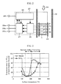
- a heating resistance type air flow rate measuring device 20 having the above-mentioned configuration includes a support 21 that supports the measurement element 1, an external circuit, and the like, as shown in Fig. 2 .
- the measurement element 1 is disposed within a subpassage 23 within a suction air passage 22 of an electronic control fuel injection system, and the external circuit is installed on an outer wall surface of the suction air passage 22.
- the heating resistor 3 and the thermal sensitive resistors 4a and 4b are electrically connected to an electronic circuit including a power supply control circuit 25 including a heating resistor heating control circuit (hereinafter, written as control circuit) 26, an output adjustment circuit 27, and the like.
- a heating temperature of the heating resistor 3 is controlled by the control circuit 26 so as to have an approximately constant difference from a suction air temperature detected by the thermal sensitive resistors 4a and 4b. Accordingly, a suction air flow can be detected on the basis of an amount of heat dissipated from the heating resistor 3 to suction air 24. In addition, the direction of the air flow can be detected using such a property that a temperature of the upstream thermal sensitive resistor is reduced.
- a flow rate detection method by the heating resistance type air flow rate measuring device 20 has other methods such as detection using a heating heater and a temperature detection resistance heated by the heating heater, and the like. However, description of each of methods in the present invention will be omitted because the methods are similar to each other.
- This heating resistance type air flow rate measuring device includes a power supply terminal 28 connected to a power supply, a flow rate output terminal 29a that outputs a flow rate signal, a temperature output terminal 29b that outputs a suction air temperature signal, and a ground terminal 29c.
- the heating resistance type air flow rate measuring device is electrically connected to an external device as well.
- the heating resistor 3 of the heating resistance type air flow rate measuring device 20 is heated and controlled during air flow rate measurement, i.e., while an engine is being driven.
- the heating resistor has a constant difference between the heating temperature of the heating resistor and the suction air temperature. Accordingly, when the suction air temperature (outdoor air temperature) is lower (for example, in a cold district), a surface temperature of the heating resistor is relatively lower.
- the heating resistance type air flow rate measuring device 20 usually uses the control circuit 26 to control the heating temperature of the heating resistor 3 so that the heating resistor 3 may be 200°C higher than the suction air temperature. Because a range of the suction air temperature is -40 to 120°C, the surface temperature of the heating resistor is set at 160 to 320°C. When the temperature of the heating resistor 3 is 320°C, there is a risk that the water-repellent and oil-repellent protective coating provided in the heating resistor described as a related art may be thermally degraded, which in turn reduces the water repellent and oil-repellent effects so that the properties of the heating resistor may be fluctuated.
- a heating resistance type air flow rate measuring device includes: a heating resistor having a surface temperature set to detect a flow rate of air sucked by an internal combustion engine; and an electronic circuit that is electrically connected to the heating resistor and outputs an signal according to the flow rate of the suction air, on the basis of an amount of heat dissipated from the heating resistor or a detected temperature.
- a water-repellent or oil-repellent material which has such properties that liquid droplets contacting a sensor surface evaporate and disappear by film boiling at a low temperature (for example, 200°C) is used for a thin film for a topmost surface layer of a thin film diaphragm.
- a thin film material that can be used at a high temperature (for example, 340°C) in the environment is used for a heating resistor thin film.
- a temperature of the heating resistor is set at a temperature equal to or higher than the temperature at which the liquid droplets contacting the sensor surface evaporate and disappear by film boiling during operation of the heating resistor type air flow meter.
- water-repellent or oil-repellent material which has such properties that liquid droplets contacting a sensor surface evaporate and disappear by film boiling at a low temperature (for example, 200°C) and the thin film material that can be used at a high temperature (for example, 360°C) in the environment.
- Fig. 3 shows a relationship between the life and a surface temperature of liquid droplets until the liquid droplets disappear when 10 ⁇ l of 3% NaCl in a form of liquid droplets is dropped onto a surface of TEOS (tetraethoxysilane), as well as onto a surface of SiO 2 , at a high temperature. Droplets on TEOS do not exhibit clear water repellency at a normal temperature.
- TEOS tetraethoxysilane
- the droplets evaporate and disappear by convection, nucleate boiling, and transition boiling, and then evaporate and disappear by film boiling at a temperature of not less than 200°C.
- a temperature of not less than 200°C since the liquid droplets are completely separated from the surface of the heating resistor by vapors, the liquid droplets stood still in a shape of a spheroid.
- the temperature of the heating resistor is not less than a temperature of film boiling, the liquid droplets do not adhere to the surface of the heating resistor while a water film is not formed thereon.
- the degrees of the droplet adherence and the water film formation are equivalent to or higher than a case where the surface of the heating resistor has water repellency or oil repellency.
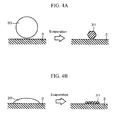
- Fig. 4A shows a form of salt on the surface of the heating resistor 3.
- salt 31 gets deposited in a massive form on the surface of the heating resistor 3 without accumulation and adherence.
- the massive salt 31 get deposited while floating from the surface of the heating resistor 3. For this reason, the massive salt 31 can be blown away by a flow of the suction air.
- the temperature of the heating resistor 3 When the temperature of the heating resistor 3 is not more than a temperature of film boiling, moisture evaporates and disappears by convection, nucleate boiling, or transition boiling with the state where the liquid droplets wet the surface of the heating resistor and adhere onto the surface of the heating resistor at a predetermined contact angle, with the state of the water film 30.
- the salt 31 As shown in Fig. 4B , the salt 31 is in contact with the heating resistor in a process of evaporation of the water film 30. For this reason, the salt 31 accumulates and adheres to the heating resistor 3. In this case, it is difficult to blow away the salt 31 by a flow of the suction air.
- the droplets on SiO 2 do not exhibit clear water repellency at a normal temperature.
- the droplets on SiO 2 evaporate and disappear by convection, nucleate boiling, and transition boiling, and then evaporate and disappear by film boiling at a temperature of not less than 300°C.
- the liquid droplets are completely separated from the surface of the heating resistor by vapors, and the liquid droplets stood still in a shape of a spheroid.
- TEOS does not exhibit clear water repellency at a normal temperature as in the case of SiO 2
- TEOS exhibits water repellency and oil repellency from the vicinity of 200°C
- TEOS exhibits water repellency and oil repellency at a temperature 100°C lower than SiO 2 does.
- a film boiling state can be expected when a protective coating is in use.
- thermal degradation of the protective coating reduces the water repellent and oil-repellent effects, which in turn fluctuates the properties of the heating resistor.
- the control circuit 26 generally controls the heating element so as to have a temperature 100 to 200°C higher than the suction air temperature detected by the thermal sensitive resistor 4. Because a range of the suction air temperature is -40 to 120°C, the surface temperature of the heating resistor of conventional products is set at 160 to 320°C or 60 to 220°C. At this temperature, not only SiO 2 but also TEOS does not exhibit water repellency and oil repellency during operation.
- a heating resistor that can be used at a high temperature (for example, 350°C) in the environment
- Pt, Ta, Mo, Ti, W, Co, Ni, Nb, Hf, Cr, Zr, Fe or the like is used for a metal layer.
- the control circuit 26 controls the heating element so as to have a temperature 300°C higher than the suction air temperature detected by the thermal sensitive resistor 4
- the surface temperature of the heating resistor according to the present invention can be set at 260 to 420°C because the range of the suction air temperature is -40 to 120°C.
- TEOS is used for the thin film of the topmost surface layer of the thin film diaphragm and is used as a water-repellent or oil-repellent material which has such properties that the liquid droplets contacting the sensor surface evaporate and disappear by film boiling at a low temperature (for example, 200°C), then no salt accumulate and adhere to the heating resistor in any environments where automobiles are in use.
- the water-repellent or oil-repellent material which has such properties that the liquid droplets contacting the sensor surface evaporate and disappear by film boiling at 200°C, for example, is used for the thin film of the topmost surface layer of the thin film diaphragm; the material that can be used at a high temperature in the environment of not less than 300°C, for example, is used for the heating resistor; and a temperature of the heating resistor is set at a temperature equal to or higher than the temperature at which the liquid droplets contacting the sensor surface evaporate and disappear by film boiling during operation of the heating resistor type air flow meter.
- fluctuation of properties due to the adhering salt as well as fluctuation of properties due to the resistance change over time can be reduced.
Landscapes
- Physics & Mathematics (AREA)
- Fluid Mechanics (AREA)
- General Physics & Mathematics (AREA)
- Measuring Volume Flow (AREA)
Abstract
Description
- The present invention relates to a measuring element provided on a diaphragm portion for thermally insulating a heating resistor and a thermal sensitive resistor from a semiconductor substrate. The present invention particularly relates to an air flow meter that measures a flow rate of air flowing through a suction air passage of an internal combustion engine.
- An air flow meter provided in a suction air passage of an internal combustion engine for an automobile and the like so as to measure an amount of suction air is required to achieve high speed response, high sensitivity, and long-term stability for the purpose of optimally controlling an engine based on an output signal to reduce fuel consumption. To meet the request, an air flow meter with high sensitivity is achieved on the basis of a semiconductor thin film layer formation technique and a micromachining technique, and employs a measuring element including a resistor that serves as a heater and that is thermally insulated from a semiconductor substrate (for example, see
JP Patent Application Publication No. 8-271308 JP Patent Application Publication No. 2000-169795 - The present invention particularly prevents adhesion of salt to a resistor type air flow meter among contaminated water, petroleum, droplets, silicone oil, soot, salt, hydrocarbon, and dust particles that exist in the installation environment. There is a problem that when rain or snow including sea salt in a coastal area or snow melting salt in a cold district is sucked, the salt intensively accumulates and adheres to the resistor. Accumulation and adhesion of the salt to the resistor cause degradation in measurement accuracy of the air flow meter over time, and also cause corrosion of materials of components including the resistor and a wiring.
- Here, a behavior of accumulation and adhesion of the salt to the resistor will be described using a behavior of water droplets including salt on a heat transfer surface. The following four states are included in a phenomenon in which a water droplet on a surface of a material is heated to disappear.
- 1. Convection: the water droplet is heated to evaporate through convection at a temperature of not more than a boiling start temperature.
- 2. Nucleate boiling: the water droplet boils only at a portion on a depression or projection of the heat transfer surface; convection occurs in the other portion.
- 3. Transition boiling: the water droplet is in a transitional state from nucleate boiling to film boiling.
- 4. Film boiling: the entire heat transfer surface is covered with vapors.
- Heat transfer under the temperature conditions of film boiling is smaller than that in nucleate boiling because the entire heat transfer surface is covered with vapors. Specifically, film boiling is quiet stable boiling caused by heat transfer within a vapor film while the heat is transferred from the heat transfer surface only through the vapor film. When a salt concentration in the water droplet increases by evaporation of the water droplet and the salt concentration exceeds the saturated concentration, the salt starts to be deposited. The water droplet is not in contact with the heat transfer surface, but is in contact with only the vapor film. For that reason, the salt gets deposited while floating in the air, and the adhesion of the salt onto the heat transfer surface is quite low. In other words, in this state, the salt does not adhere closely to the heat transfer surface. On the other hand, under the temperature conditions of transition boiling and nucleate boiling, the heat transfer surface partly has a boiling region and a non-boiling region. In the non-boiling region, the heat transfer surface is in contact with the water droplet. The salt concentration in the water droplet increases as the water evaporates. The salt starts to be deposited when the salt concentration exceeds the saturated concentration. The adhesion of the salt onto the heat transfer surface is high because the water droplet is in contact with the heat transfer surface and the salt gets deposited on the heat transfer surface. In other words, in this state, the salt adheres closely to the heat transfer surface. From above, under the condition that the heating resistor is at or below the temperature of transition boiling and that of nucleate boiling, the salt accumulates and fixedly adheres to the heat transfer surface.
- In the above-mentioned related art, an attempt has been made to provide a sensor element with a water-repellent or oil-repellent coating made of an organic-based material to prevent accumulation and adhesion of the salt on the resistor when the liquid droplets including the salt evaporate and disappear while being in contact with the resistor. However, when a surface temperature of the resistor is high, the water-repellent or oil-repellent coating made of an organic-based material is degraded due to thermal oxidation. Thus, use of such a water repellent or oil-repellent coating has risks of reducing the water-repellent and oil-repellent effects, and fluctuating properties of the resistor.
- An object of the present invention is to prevent accumulation and adhesion of salt included in liquid droplets contacting a surface of a heating resistor, thereby to reduce contamination and corrosion of the heating resistor and to suppress reduction in measurement accuracy of a heating resistor type air flow meter.
- In order to achieve the above-mentioned object, a water-repellent or oil-repellent material used in a semiconductor process and having such a property that liquid droplets contacting a sensor surface evaporate and disappear by film boiling at 200°C, for example, is used for a thin layer of the topmost surface layer of a thin film diaphragm; a material that can be used at a high temperature in the environment, for example, not less than 300°C is used for the heating resistor; and a temperature of the heating resistor is set at a temperature equal to or higher than the temperature at which the liquid droplets contacting the sensor surface evaporate and disappear by film boiling during operation of a heating resistor type air flow rate sensor. Here, the temperature of the heating resistor is not intended to be set as high as possible. If the temperature is set too high, the life of the heating resistor in the heating resistance type air flow rate measuring device is remarkably short, or electronic components and a connection portion mounted on an electronic circuit may be degraded or broken down due to constant exposure to the high temperature. Accordingly, the maximum temperature is set at 460°C or less, for example.
- To achieve the above-mentioned object, tetraethoxysilane (Si(OC2H5)4, hereinafter, referred to as TEOS) or the like is used for the topmost surface layer of a thin film diaphragm. Ta, Mo, Ti, W, Co, Ni, Nb, Hf, Cr, Zr or Fe is used for a metal layer in a heating resistor of the thin film diaphragm. A temperature of the heating resistor is set at a temperature equal to or higher than the temperature at which the liquid droplets contacting a sensor surface evaporate and disappear by film boiling during operation of a heating resistor type air flow meter.
- Accumulation and adhesion of the salt included in the liquid droplets contacting the surface of the heating resistor are prevented to reduce contamination and corrosion of the heating resistor and to suppress reduction in measurement accuracy of the heating resistor type air flow meter.
-
-
Fig. 1 is a diagram showing one embodiment of a measurement element provided in a heating resistance type air flow rate sensor to which the present invention is applied;Fig. 1A is a schematic plan view thereof; andFig. 1B is an enlarged sectional view taken along line A-A ofFig. 1A . -
Fig. 2 is a diagram showing a schematic configuration according to one embodiment of a measurement element provided in the heating resistance type air flow rate sensor to which the present invention is applied. -
Fig. 3 is a relationship diagram between the life and a surface temperature of liquid droplets until the liquid droplets on a high temperature surface evaporate and disappear. -
Figs. 4A and 4B are diagrams each showing a form of salt on a surface of the heating resistor. - Hereinafter, an embodiment according to the present invention will be described.
- Hereinafter, a heat type air flow rate sensor using a diaphragm sensor according to the present invention will be described as an example.
Fig. 1A is a schematic plan view of a measurement element 1 of the air flow rate sensor, andFig. 1B is an enlarged sectional view taken along line A-A ofFig. 1A . The heat type air flow rate sensor measurement element 1 according to the present embodiment is formed of asemiconductor substrate 2, aheating resistor 3, an upstream thermalsensitive resistor 4a, a downstream thermalsensitive resistor 4b, an air temperature thermalsensitive resistor 5, and the like, as shown inFig. 1A . Athin film diaphragm 10a having ahollow portion 10 is formed in a central part on a bottom surface of thesemiconductor substrate 2 made of a single crystal silicon substrate having a rectangular shape. Theheating resistor 3, the upstream thermalsensitive resistor 4a, and the downstream thermalsensitive resistor 4b are formed on thethin film diaphragm 10a. The air temperature thermalsensitive resistor 5 is formed on the outside of thethin film diaphragm 10a of thesemiconductor substrate 2. A terminal 9 for electrically connecting theheating resistor 3, the upstream thermalsensitive resistor 4a, the downstream thermalsensitive resistor 4b, and the air temperature thermalsensitive resistor 5 to an external circuit is formed on the outside of thethin film diaphragm 10a of thesemiconductor substrate 2. Each of theheating resistor 3, the thermalsensitive resistor 4, and the air temperature thermalsensitive resistor 5 may be formed so as to be turned back several times. A configuration of the resistor varies with measurement methods, and the configuration here is shown as an example. Theheating resistor 3 that functions as a microheater, the thermalsensitive resistors sensitive resistor 5 may have the same film structure or may have a different film structure. InFig. 1B which shows a cross section of thethin film diaphragm 10a along line A-A shown inFig. 1A , theheating resistor 3 and the thermalsensitive resistors electrical insulation films 6 and 7 on one side and an upper thin film of an electrical insulation film 8 on the other. - A heating resistance type air flow
rate measuring device 20 having the above-mentioned configuration includes asupport 21 that supports the measurement element 1, an external circuit, and the like, as shown inFig. 2 . The measurement element 1 is disposed within asubpassage 23 within asuction air passage 22 of an electronic control fuel injection system, and the external circuit is installed on an outer wall surface of thesuction air passage 22. Theheating resistor 3 and the thermalsensitive resistors supply control circuit 25 including a heating resistor heating control circuit (hereinafter, written as control circuit) 26, anoutput adjustment circuit 27, and the like. A heating temperature of theheating resistor 3 is controlled by thecontrol circuit 26 so as to have an approximately constant difference from a suction air temperature detected by the thermalsensitive resistors heating resistor 3 tosuction air 24. In addition, the direction of the air flow can be detected using such a property that a temperature of the upstream thermal sensitive resistor is reduced. A flow rate detection method by the heating resistance type air flowrate measuring device 20 has other methods such as detection using a heating heater and a temperature detection resistance heated by the heating heater, and the like. However, description of each of methods in the present invention will be omitted because the methods are similar to each other. This heating resistance type air flow rate measuring device includes apower supply terminal 28 connected to a power supply, a flowrate output terminal 29a that outputs a flow rate signal, atemperature output terminal 29b that outputs a suction air temperature signal, and aground terminal 29c. The heating resistance type air flow rate measuring device is electrically connected to an external device as well. - The
heating resistor 3 of the heating resistance type air flowrate measuring device 20 is heated and controlled during air flow rate measurement, i.e., while an engine is being driven. The heating resistor has a constant difference between the heating temperature of the heating resistor and the suction air temperature. Accordingly, when the suction air temperature (outdoor air temperature) is lower (for example, in a cold district), a surface temperature of the heating resistor is relatively lower. - Although the heating temperature of the
heating resistor 3 is different depending on models, the heating resistance type air flowrate measuring device 20 usually uses thecontrol circuit 26 to control the heating temperature of theheating resistor 3 so that theheating resistor 3 may be 200°C higher than the suction air temperature. Because a range of the suction air temperature is -40 to 120°C, the surface temperature of the heating resistor is set at 160 to 320°C. When the temperature of theheating resistor 3 is 320°C, there is a risk that the water-repellent and oil-repellent protective coating provided in the heating resistor described as a related art may be thermally degraded, which in turn reduces the water repellent and oil-repellent effects so that the properties of the heating resistor may be fluctuated. A related art in which an organic water-repellent and oil-repellent protective coating is decomposed to disappear at a high temperature is also reported. However, there is a conceivable risk that insufficient decomposition and disappearance of the protective coating undesirably fluctuates the properties of the heating resistor in the environment where the suction air temperature changes in the range of -40 to 120°C. - According to the description above, a heating resistance type air flow meter is configured as follows. A heating resistance type air flow rate measuring device includes: a heating resistor having a surface temperature set to detect a flow rate of air sucked by an internal combustion engine; and an electronic circuit that is electrically connected to the heating resistor and outputs an signal according to the flow rate of the suction air, on the basis of an amount of heat dissipated from the heating resistor or a detected temperature. As for the heating resistance type air flow meter, a water-repellent or oil-repellent material which has such properties that liquid droplets contacting a sensor surface evaporate and disappear by film boiling at a low temperature (for example, 200°C) is used for a thin film for a topmost surface layer of a thin film diaphragm. Moreover, a thin film material that can be used at a high temperature (for example, 340°C) in the environment is used for a heating resistor thin film. Furthermore, a temperature of the heating resistor is set at a temperature equal to or higher than the temperature at which the liquid droplets contacting the sensor surface evaporate and disappear by film boiling during operation of the heating resistor type air flow meter.
- Here, description will be given of the water-repellent or oil-repellent material which has such properties that liquid droplets contacting a sensor surface evaporate and disappear by film boiling at a low temperature (for example, 200°C) and the thin film material that can be used at a high temperature (for example, 360°C) in the environment.
- First, the water-repellent or oil-repellent material which has such properties that liquid droplets contacting a sensor surface evaporate and disappear by film boiling at a low temperature (for example, 200°C) will be described.
Fig. 3 shows a relationship between the life and a surface temperature of liquid droplets until the liquid droplets disappear when 10 µl of 3% NaCl in a form of liquid droplets is dropped onto a surface of TEOS (tetraethoxysilane), as well as onto a surface of SiO2, at a high temperature. Droplets on TEOS do not exhibit clear water repellency at a normal temperature. As the surface temperature rises, the droplets evaporate and disappear by convection, nucleate boiling, and transition boiling, and then evaporate and disappear by film boiling at a temperature of not less than 200°C. At a temperature of not less than 200°C, since the liquid droplets are completely separated from the surface of the heating resistor by vapors, the liquid droplets stood still in a shape of a spheroid. As described above, when the temperature of the heating resistor is not less than a temperature of film boiling, the liquid droplets do not adhere to the surface of the heating resistor while a water film is not formed thereon. In this case, the degrees of the droplet adherence and the water film formation are equivalent to or higher than a case where the surface of the heating resistor has water repellency or oil repellency. Even when the liquid droplets remain in concave portions of the heating resistor, the liquid droplet is completely separated by vapors from the surface of the heating resistor.Fig. 4A shows a form of salt on the surface of theheating resistor 3. Here, even when aliquid droplet 30 evaporates and disappears,salt 31 gets deposited in a massive form on the surface of theheating resistor 3 without accumulation and adherence. Themassive salt 31 get deposited while floating from the surface of theheating resistor 3. For this reason, themassive salt 31 can be blown away by a flow of the suction air. When the temperature of theheating resistor 3 is not more than a temperature of film boiling, moisture evaporates and disappears by convection, nucleate boiling, or transition boiling with the state where the liquid droplets wet the surface of the heating resistor and adhere onto the surface of the heating resistor at a predetermined contact angle, with the state of thewater film 30. In this case, as shown inFig. 4B , thesalt 31 is in contact with the heating resistor in a process of evaporation of thewater film 30. For this reason, thesalt 31 accumulates and adheres to theheating resistor 3. In this case, it is difficult to blow away thesalt 31 by a flow of the suction air. On the other hand, the droplets on SiO2 do not exhibit clear water repellency at a normal temperature. As the surface temperature rises, the droplets on SiO2 evaporate and disappear by convection, nucleate boiling, and transition boiling, and then evaporate and disappear by film boiling at a temperature of not less than 300°C. At a temperature of not less than 300°C, the liquid droplets are completely separated from the surface of the heating resistor by vapors, and the liquid droplets stood still in a shape of a spheroid. As mentioned above, the present inventors have found out that although TEOS does not exhibit clear water repellency at a normal temperature as in the case of SiO2, TEOS exhibits water repellency and oil repellency from the vicinity of 200°C, in other words, TEOS exhibits water repellency and oil repellency at atemperature 100°C lower than SiO2 does. A film boiling state can be expected when a protective coating is in use. However, as mentioned above, there is a conceivable risk that thermal degradation of the protective coating reduces the water repellent and oil-repellent effects, which in turn fluctuates the properties of the heating resistor. - When a material, such as TEOS, which has water repellency and oil repellency in the vicinity of 200°C, is used for a thin film of a different surface layer of the thin film diaphragm, fluctuation of properties due to adhering salt can be reduced. However, there is a conceivable risk that resistance may change over time at 200°C, depending on the material of the heating resistor. Accordingly, description will be given next of the thin film material that can be used in a high temperature in the environment.
- From a viewpoint of resistance change over time of the heating resistor at a high temperature in the environment, the
control circuit 26 generally controls the heating element so as to have atemperature 100 to 200°C higher than the suction air temperature detected by the thermalsensitive resistor 4. Because a range of the suction air temperature is -40 to 120°C, the surface temperature of the heating resistor of conventional products is set at 160 to 320°C or 60 to 220°C. At this temperature, not only SiO2 but also TEOS does not exhibit water repellency and oil repellency during operation. As a heating resistor that can be used at a high temperature (for example, 350°C) in the environment, Pt, Ta, Mo, Ti, W, Co, Ni, Nb, Hf, Cr, Zr, Fe or the like is used for a metal layer. For example, when thecontrol circuit 26 controls the heating element so as to have atemperature 300°C higher than the suction air temperature detected by the thermalsensitive resistor 4, the surface temperature of the heating resistor according to the present invention can be set at 260 to 420°C because the range of the suction air temperature is -40 to 120°C. At this set temperature, if TEOS is used for the thin film of the topmost surface layer of the thin film diaphragm and is used as a water-repellent or oil-repellent material which has such properties that the liquid droplets contacting the sensor surface evaporate and disappear by film boiling at a low temperature (for example, 200°C), then no salt accumulate and adhere to the heating resistor in any environments where automobiles are in use. - As described above, the water-repellent or oil-repellent material which has such properties that the liquid droplets contacting the sensor surface evaporate and disappear by film boiling at 200°C, for example, is used for the thin film of the topmost surface layer of the thin film diaphragm; the material that can be used at a high temperature in the environment of not less than 300°C, for example, is used for the heating resistor; and a temperature of the heating resistor is set at a temperature equal to or higher than the temperature at which the liquid droplets contacting the sensor surface evaporate and disappear by film boiling during operation of the heating resistor type air flow meter. Thus, fluctuation of properties due to the adhering salt as well as fluctuation of properties due to the resistance change over time can be reduced.
- Features, components and specific details of the structures of the above-described embodiments may be exchanged or combined to form further embodiments optimized for the respective application. As far as those modifications are apparent for an expert skilled in the art they shall be disclosed implicitly by the above description without specifying explicitly every possible combination.
-
- 1
- heat type air flow rate sensor measurement element
- 2
- semiconductor substrate
- 3
- heating resistor
- 4a
- upstream thermal sensitive resistor
- 4b
- downstream thermal sensitive resistor
- 5
- air-temperature thermal sensitive resistor
- 6, 7, and 8
- electrical insulation film
- 10
- hollow portion
- 10a
- thin film diaphragm
- 21
- support
- 22
- suction air passage
- 23
- subpassage
- 25
- power supply control circuit
- 26
- heating resistor heating control circuit
- 27
- output adjustment circuit
- 28
- power supply terminal
- 29a and 29b
- output terminal
- 29c
- ground terminal
- 30
- liquid droplet
- 31
- salt
Claims (3)
- A heating resistance type air flow rate measuring device, comprising a measuring element including:a semiconductor substrate (2);an electrical insulation film (6, 7) formed on the semiconductor substrate (2);a resistor that constitutes a heater formed on the electrical insulation film (6, 7); anda hollow portion (10) formed by removing a portion of the semiconductor substrate (2) corresponding to a formation region of a resistor main body, thereby the hollow portion (10) forming the formation region of the resistor main body into a thin-wall portion, whereina thin film material exhibiting water repellency or oil repellency at a temperature equal to or higher than a temperature at which liquid droplets contacting a sensor surface evaporate and disappear by film boiling is formed on a topmost surface of a thin film diaphragm (10a) including a heating resistor (3), anda temperature of the heating resistor (3) in operation is set at a temperature equal to or higher than the temperature at which the liquid droplets contacting the sensor surface evaporate and disappear by film boiling.
- A heating resistance type air flow rate measuring device according to claim 1, characterized by
an electronic circuit that is electrically connected to the heating resistor (3) and outputs a signal according to a flow rate of the sucked air on the basis of an amount of heat dissipated from the heating resistor (3) or a detected temperature, wherein
a metal layer of a Ta film, a Mo film, a Ti film, a W film, a Co film, a Ni film, a Nb film, a Hf film, a Cr film, a Zr film, or a Fe film is formed as the heating resistor (3),
tetraethoxysilane is formed on a topmost surface of a thin film diaphragm (10a) including the heating resistor (3), and
a temperature of the heating resistor (3) is set at a temperature of not less than 200°C during operation of a heating resistor (3) type air flow rate sensor. - A heating resistance type air flow rate measuring device, comprising:a heating resistor (3) in which a surface temperature is set to detect a flow rate of air sucked by an internal combustion engine; andan electronic circuit that is electrically connected to the heating resistor (3) and outputs a signal according to a flow rate of the sucked air on the basis of an amount of heat dissipated from the heating resistor (3) or a detected temperature, whereina metal layer of a Ta film, a Mo film, a Ti film, a W film, a Co film, a Ni film, a Nb film, a Hf film, a Cr film, a Zr film, or a Fe film is formed as the heating resistor (3),tetraethoxysilane is formed on a topmost surface of a thin film diaphragm (10a) including the heating resistor (3), anda temperature of the heating resistor (3) is set at a temperature of not less than 200°C during operation of a heating resistor (3) type air flow rate sensor.
Applications Claiming Priority (1)
| Application Number | Priority Date | Filing Date | Title |
|---|---|---|---|
| JP2009219893A JP5114463B2 (en) | 2009-09-25 | 2009-09-25 | Heat resistance type air flow measuring device |
Publications (1)
| Publication Number | Publication Date |
|---|---|
| EP2302335A1 true EP2302335A1 (en) | 2011-03-30 |
Family
ID=43303787
Family Applications (1)
| Application Number | Title | Priority Date | Filing Date |
|---|---|---|---|
| EP10170080A Withdrawn EP2302335A1 (en) | 2009-09-25 | 2010-07-20 | Heating resistance type air flow rate measuring device |
Country Status (3)
| Country | Link |
|---|---|
| US (1) | US20110072897A1 (en) |
| EP (1) | EP2302335A1 (en) |
| JP (1) | JP5114463B2 (en) |
Families Citing this family (4)
| Publication number | Priority date | Publication date | Assignee | Title |
|---|---|---|---|---|
| JP6126417B2 (en) * | 2013-03-12 | 2017-05-10 | 日立オートモティブシステムズ株式会社 | Thermal flow meter |
| DE102014226079B4 (en) * | 2014-12-16 | 2026-04-23 | Robert Bosch Gmbh | Method and device for diagnosing an auxiliary heating function of an air mass sensor |
| KR101699336B1 (en) * | 2015-01-08 | 2017-02-13 | 주식회사 현대케피코 | air flow sensor for preventing pollution |
| JP5936744B1 (en) * | 2015-05-15 | 2016-06-22 | 三菱電機株式会社 | Flow measuring device |
Citations (5)
| Publication number | Priority date | Publication date | Assignee | Title |
|---|---|---|---|---|
| JPH08271308A (en) | 1995-03-29 | 1996-10-18 | Robert Bosch Gmbh | Measuring element for flow sensor and manufacturing method thereof |
| JP2000169795A (en) | 1998-10-14 | 2000-06-20 | Robert Bosch Gmbh | Sensor element or actuator element with anti-adhesion surface coating |
| JP2003337056A (en) * | 2002-05-17 | 2003-11-28 | Hitachi Ltd | Heating resistance type air flow measurement device |
| US20090016403A1 (en) * | 2007-07-09 | 2009-01-15 | Chih-Chang Chen | Micromachined gas and liquid concentration sensor and method of making the same |
| EP2085754A2 (en) * | 2008-01-29 | 2009-08-05 | Hitachi Ltd. | Flow sensor with metal film resistor |
Family Cites Families (15)
| Publication number | Priority date | Publication date | Assignee | Title |
|---|---|---|---|---|
| US4909078A (en) * | 1987-10-14 | 1990-03-20 | Rosemount Inc. | Fluid flow detector |
| JPH0829224A (en) * | 1994-07-14 | 1996-02-02 | Mitsubishi Electric Corp | Flow rate detector |
| JPH0829226A (en) * | 1994-07-20 | 1996-02-02 | Tokyo Gas Co Ltd | Thermal semiconductor flow sensor and manufacturing method thereof |
| CN1645061A (en) * | 1997-11-21 | 2005-07-27 | 三井金属矿业株式会社 | Flow sensor and temperature sensor |
| US6696346B2 (en) * | 1997-12-24 | 2004-02-24 | Rohm Co., Ltd. | Method of manufacturing semiconductor device |
| JP2000227352A (en) * | 1999-02-08 | 2000-08-15 | Denso Corp | Thermal flow sensor |
| US6703241B1 (en) * | 1999-11-15 | 2004-03-09 | Cyrano Sciences, Inc. | Referencing and rapid sampling in artificial olfactometry |
| JP2001272260A (en) * | 2000-03-27 | 2001-10-05 | Ngk Spark Plug Co Ltd | Mass flow sensor and mass flow meter using the same |
| US7594507B2 (en) * | 2001-01-16 | 2009-09-29 | Hewlett-Packard Development Company, L.P. | Thermal generation of droplets for aerosol |
| JP3817497B2 (en) * | 2002-06-10 | 2006-09-06 | 株式会社日立製作所 | Thermal flow meter |
| KR100723357B1 (en) * | 2004-10-28 | 2007-05-30 | 마쯔시다덴기산교 가부시키가이샤 | Piezoelectric elements and manufacturing method of the same |
| JP4966526B2 (en) * | 2005-09-07 | 2012-07-04 | 日立オートモティブシステムズ株式会社 | Flow sensor |
| JP2007248136A (en) * | 2006-03-14 | 2007-09-27 | Hitachi Ltd | Thermal gas flow measuring device |
| JP5406674B2 (en) * | 2009-11-06 | 2014-02-05 | 日立オートモティブシステムズ株式会社 | Thermal fluid flow sensor and manufacturing method thereof |
| JP5526065B2 (en) * | 2011-03-25 | 2014-06-18 | 日立オートモティブシステムズ株式会社 | Thermal sensor and manufacturing method thereof |
-
2009
- 2009-09-25 JP JP2009219893A patent/JP5114463B2/en active Active
-
2010
- 2010-07-01 US US12/829,105 patent/US20110072897A1/en not_active Abandoned
- 2010-07-20 EP EP10170080A patent/EP2302335A1/en not_active Withdrawn
Patent Citations (5)
| Publication number | Priority date | Publication date | Assignee | Title |
|---|---|---|---|---|
| JPH08271308A (en) | 1995-03-29 | 1996-10-18 | Robert Bosch Gmbh | Measuring element for flow sensor and manufacturing method thereof |
| JP2000169795A (en) | 1998-10-14 | 2000-06-20 | Robert Bosch Gmbh | Sensor element or actuator element with anti-adhesion surface coating |
| JP2003337056A (en) * | 2002-05-17 | 2003-11-28 | Hitachi Ltd | Heating resistance type air flow measurement device |
| US20090016403A1 (en) * | 2007-07-09 | 2009-01-15 | Chih-Chang Chen | Micromachined gas and liquid concentration sensor and method of making the same |
| EP2085754A2 (en) * | 2008-01-29 | 2009-08-05 | Hitachi Ltd. | Flow sensor with metal film resistor |
Also Published As
| Publication number | Publication date |
|---|---|
| US20110072897A1 (en) | 2011-03-31 |
| JP5114463B2 (en) | 2013-01-09 |
| JP2011069677A (en) | 2011-04-07 |
Similar Documents
| Publication | Publication Date | Title |
|---|---|---|
| EP2068128B1 (en) | Thermal type flow meter for engine control system | |
| US6349596B1 (en) | Thermal type air flow sensor | |
| US7552633B2 (en) | Thermal type gas flowmeter | |
| JP3817497B2 (en) | Thermal flow meter | |
| US9038454B2 (en) | Thermal flowmeter | |
| US7587938B2 (en) | Thermal type flow meter including a secondary heating device to suppress heat transfer | |
| US20110072897A1 (en) | Heating Resistance Type Air Flow Rate Measuring Device | |
| JP4474771B2 (en) | Flow measuring device | |
| JPWO2004106863A1 (en) | Thermal flow sensor | |
| JP2010085137A (en) | Air flow meter | |
| JP4845440B2 (en) | Thermal flow meter | |
| CN101156051A (en) | Method for operating a hot film air mass meter | |
| JP4253969B2 (en) | Micro heater, manufacturing method thereof, and flow sensor | |
| JP4481552B2 (en) | Heat resistance type air flow measuring device | |
| JP6126417B2 (en) | Thermal flow meter | |
| JPH04230003A (en) | Resistor device | |
| US10989579B2 (en) | Thermal detection sensor | |
| JP6255162B2 (en) | Manufacturing method of gas sensor | |
| JP3638786B2 (en) | Flow rate detecting element and flow rate sensor | |
| WO2003102974A1 (en) | Platinum thin film and thermal sensor | |
| JP2000111377A (en) | Flow rate sensor and method of manufacturing flow rate sensor | |
| RU2456551C1 (en) | Sensor for monitoring liquid level | |
| JP2002131106A (en) | Micro heater and thermal air flow meter | |
| KR101699336B1 (en) | air flow sensor for preventing pollution | |
| JP5315196B2 (en) | Air flow meter |
Legal Events
| Date | Code | Title | Description |
|---|---|---|---|
| PUAI | Public reference made under article 153(3) epc to a published international application that has entered the european phase |
Free format text: ORIGINAL CODE: 0009012 |
|
| 17P | Request for examination filed |
Effective date: 20101119 |
|
| AK | Designated contracting states |
Kind code of ref document: A1 Designated state(s): AL AT BE BG CH CY CZ DE DK EE ES FI FR GB GR HR HU IE IS IT LI LT LU LV MC MK MT NL NO PL PT RO SE SI SK SM TR |
|
| AX | Request for extension of the european patent |
Extension state: BA ME RS |
|
| STAA | Information on the status of an ep patent application or granted ep patent |
Free format text: STATUS: EXAMINATION IS IN PROGRESS |
|
| 17Q | First examination report despatched |
Effective date: 20171120 |
|
| STAA | Information on the status of an ep patent application or granted ep patent |
Free format text: STATUS: THE APPLICATION IS DEEMED TO BE WITHDRAWN |
|
| 18D | Application deemed to be withdrawn |
Effective date: 20180404 |