EP2301875A1 - Intermittent cutting and transfer device - Google Patents
Intermittent cutting and transfer device Download PDFInfo
- Publication number
- EP2301875A1 EP2301875A1 EP09773459A EP09773459A EP2301875A1 EP 2301875 A1 EP2301875 A1 EP 2301875A1 EP 09773459 A EP09773459 A EP 09773459A EP 09773459 A EP09773459 A EP 09773459A EP 2301875 A1 EP2301875 A1 EP 2301875A1
- Authority
- EP
- European Patent Office
- Prior art keywords
- film sheet
- suction
- blade roll
- lower blade
- cut
- Prior art date
- Legal status (The legal status is an assumption and is not a legal conclusion. Google has not performed a legal analysis and makes no representation as to the accuracy of the status listed.)
- Granted
Links
Images


Classifications
-
- B—PERFORMING OPERATIONS; TRANSPORTING
- B65—CONVEYING; PACKING; STORING; HANDLING THIN OR FILAMENTARY MATERIAL
- B65H—HANDLING THIN OR FILAMENTARY MATERIAL, e.g. SHEETS, WEBS, CABLES
- B65H39/00—Associating, collating, or gathering articles or webs
- B65H39/14—Associating sheets with webs
-
- A—HUMAN NECESSITIES
- A61—MEDICAL OR VETERINARY SCIENCE; HYGIENE
- A61F—FILTERS IMPLANTABLE INTO BLOOD VESSELS; PROSTHESES; DEVICES PROVIDING PATENCY TO, OR PREVENTING COLLAPSING OF, TUBULAR STRUCTURES OF THE BODY, e.g. STENTS; ORTHOPAEDIC, NURSING OR CONTRACEPTIVE DEVICES; FOMENTATION; TREATMENT OR PROTECTION OF EYES OR EARS; BANDAGES, DRESSINGS OR ABSORBENT PADS; FIRST-AID KITS
- A61F13/00—Bandages or dressings; Absorbent pads
- A61F13/15—Absorbent pads, e.g. sanitary towels, swabs or tampons for external or internal application to the body; Supporting or fastening means therefor; Tampon applicators
- A61F13/15577—Apparatus or processes for manufacturing
- A61F13/15707—Mechanical treatment, e.g. notching, twisting, compressing, shaping
- A61F13/15723—Partitioning batts; Cutting
-
- A—HUMAN NECESSITIES
- A61—MEDICAL OR VETERINARY SCIENCE; HYGIENE
- A61F—FILTERS IMPLANTABLE INTO BLOOD VESSELS; PROSTHESES; DEVICES PROVIDING PATENCY TO, OR PREVENTING COLLAPSING OF, TUBULAR STRUCTURES OF THE BODY, e.g. STENTS; ORTHOPAEDIC, NURSING OR CONTRACEPTIVE DEVICES; FOMENTATION; TREATMENT OR PROTECTION OF EYES OR EARS; BANDAGES, DRESSINGS OR ABSORBENT PADS; FIRST-AID KITS
- A61F13/00—Bandages or dressings; Absorbent pads
- A61F13/15—Absorbent pads, e.g. sanitary towels, swabs or tampons for external or internal application to the body; Supporting or fastening means therefor; Tampon applicators
- A61F13/15577—Apparatus or processes for manufacturing
- A61F13/15764—Transferring, feeding or handling devices; Drives
-
- B—PERFORMING OPERATIONS; TRANSPORTING
- B26—HAND CUTTING TOOLS; CUTTING; SEVERING
- B26D—CUTTING; DETAILS COMMON TO MACHINES FOR PERFORATING, PUNCHING, CUTTING-OUT, STAMPING-OUT OR SEVERING
- B26D1/00—Cutting through work characterised by the nature or movement of the cutting member or particular materials not otherwise provided for; Apparatus or machines therefor; Cutting members therefor
- B26D1/01—Cutting through work characterised by the nature or movement of the cutting member or particular materials not otherwise provided for; Apparatus or machines therefor; Cutting members therefor involving a cutting member which does not travel with the work
- B26D1/12—Cutting through work characterised by the nature or movement of the cutting member or particular materials not otherwise provided for; Apparatus or machines therefor; Cutting members therefor involving a cutting member which does not travel with the work having a cutting member moving about an axis
- B26D1/25—Cutting through work characterised by the nature or movement of the cutting member or particular materials not otherwise provided for; Apparatus or machines therefor; Cutting members therefor involving a cutting member which does not travel with the work having a cutting member moving about an axis with a non-circular cutting member
- B26D1/34—Cutting through work characterised by the nature or movement of the cutting member or particular materials not otherwise provided for; Apparatus or machines therefor; Cutting members therefor involving a cutting member which does not travel with the work having a cutting member moving about an axis with a non-circular cutting member moving about an axis parallel to the line of cut
- B26D1/40—Cutting through work characterised by the nature or movement of the cutting member or particular materials not otherwise provided for; Apparatus or machines therefor; Cutting members therefor involving a cutting member which does not travel with the work having a cutting member moving about an axis with a non-circular cutting member moving about an axis parallel to the line of cut and coacting with a rotary member
- B26D1/405—Cutting through work characterised by the nature or movement of the cutting member or particular materials not otherwise provided for; Apparatus or machines therefor; Cutting members therefor involving a cutting member which does not travel with the work having a cutting member moving about an axis with a non-circular cutting member moving about an axis parallel to the line of cut and coacting with a rotary member for thin material, e.g. for sheets, strips or the like
-
- B—PERFORMING OPERATIONS; TRANSPORTING
- B26—HAND CUTTING TOOLS; CUTTING; SEVERING
- B26D—CUTTING; DETAILS COMMON TO MACHINES FOR PERFORATING, PUNCHING, CUTTING-OUT, STAMPING-OUT OR SEVERING
- B26D7/00—Details of apparatus for cutting, cutting-out, stamping-out, punching, perforating, or severing by means other than cutting
- B26D7/01—Means for holding or positioning work
- B26D7/018—Holding the work by suction
-
- B—PERFORMING OPERATIONS; TRANSPORTING
- B65—CONVEYING; PACKING; STORING; HANDLING THIN OR FILAMENTARY MATERIAL
- B65H—HANDLING THIN OR FILAMENTARY MATERIAL, e.g. SHEETS, WEBS, CABLES
- B65H35/00—Delivering articles from cutting or line-perforating machines; Article or web delivery apparatus incorporating cutting or line-perforating devices, e.g. adhesive tape dispensers
- B65H35/04—Delivering articles from cutting or line-perforating machines; Article or web delivery apparatus incorporating cutting or line-perforating devices, e.g. adhesive tape dispensers from or with transverse cutters or perforators
- B65H35/08—Delivering articles from cutting or line-perforating machines; Article or web delivery apparatus incorporating cutting or line-perforating devices, e.g. adhesive tape dispensers from or with transverse cutters or perforators from or with revolving, e.g. cylinder, cutters or perforators
-
- B—PERFORMING OPERATIONS; TRANSPORTING
- B65—CONVEYING; PACKING; STORING; HANDLING THIN OR FILAMENTARY MATERIAL
- B65H—HANDLING THIN OR FILAMENTARY MATERIAL, e.g. SHEETS, WEBS, CABLES
- B65H2301/00—Handling processes for sheets or webs
- B65H2301/10—Selective handling processes
- B65H2301/12—Selective handling processes of sheets or web
- B65H2301/121—Selective handling processes of sheets or web for sheet handling processes, i.e. wherein the web is cut into sheets
-
- B—PERFORMING OPERATIONS; TRANSPORTING
- B65—CONVEYING; PACKING; STORING; HANDLING THIN OR FILAMENTARY MATERIAL
- B65H—HANDLING THIN OR FILAMENTARY MATERIAL, e.g. SHEETS, WEBS, CABLES
- B65H2406/00—Means using fluid
- B65H2406/30—Suction means
- B65H2406/33—Rotary suction means, e.g. roller, cylinder or drum
- B65H2406/332—Details on suction openings
-
- Y—GENERAL TAGGING OF NEW TECHNOLOGICAL DEVELOPMENTS; GENERAL TAGGING OF CROSS-SECTIONAL TECHNOLOGIES SPANNING OVER SEVERAL SECTIONS OF THE IPC; TECHNICAL SUBJECTS COVERED BY FORMER USPC CROSS-REFERENCE ART COLLECTIONS [XRACs] AND DIGESTS
- Y10—TECHNICAL SUBJECTS COVERED BY FORMER USPC
- Y10T—TECHNICAL SUBJECTS COVERED BY FORMER US CLASSIFICATION
- Y10T156/00—Adhesive bonding and miscellaneous chemical manufacture
- Y10T156/12—Surface bonding means and/or assembly means with cutting, punching, piercing, severing or tearing
- Y10T156/125—Plural severing means each acting on a different work piece
-
- Y—GENERAL TAGGING OF NEW TECHNOLOGICAL DEVELOPMENTS; GENERAL TAGGING OF CROSS-SECTIONAL TECHNOLOGIES SPANNING OVER SEVERAL SECTIONS OF THE IPC; TECHNICAL SUBJECTS COVERED BY FORMER USPC CROSS-REFERENCE ART COLLECTIONS [XRACs] AND DIGESTS
- Y10—TECHNICAL SUBJECTS COVERED BY FORMER USPC
- Y10T—TECHNICAL SUBJECTS COVERED BY FORMER US CLASSIFICATION
- Y10T156/00—Adhesive bonding and miscellaneous chemical manufacture
- Y10T156/12—Surface bonding means and/or assembly means with cutting, punching, piercing, severing or tearing
- Y10T156/1317—Means feeding plural workpieces to be joined
- Y10T156/1322—Severing before bonding or assembling of parts
- Y10T156/133—Delivering cut part to indefinite or running length web
-
- Y—GENERAL TAGGING OF NEW TECHNOLOGICAL DEVELOPMENTS; GENERAL TAGGING OF CROSS-SECTIONAL TECHNOLOGIES SPANNING OVER SEVERAL SECTIONS OF THE IPC; TECHNICAL SUBJECTS COVERED BY FORMER USPC CROSS-REFERENCE ART COLLECTIONS [XRACs] AND DIGESTS
- Y10—TECHNICAL SUBJECTS COVERED BY FORMER USPC
- Y10T—TECHNICAL SUBJECTS COVERED BY FORMER US CLASSIFICATION
- Y10T83/00—Cutting
- Y10T83/202—With product handling means
- Y10T83/2066—By fluid current
- Y10T83/207—By suction means
-
- Y—GENERAL TAGGING OF NEW TECHNOLOGICAL DEVELOPMENTS; GENERAL TAGGING OF CROSS-SECTIONAL TECHNOLOGIES SPANNING OVER SEVERAL SECTIONS OF THE IPC; TECHNICAL SUBJECTS COVERED BY FORMER USPC CROSS-REFERENCE ART COLLECTIONS [XRACs] AND DIGESTS
- Y10—TECHNICAL SUBJECTS COVERED BY FORMER USPC
- Y10T—TECHNICAL SUBJECTS COVERED BY FORMER US CLASSIFICATION
- Y10T83/00—Cutting
- Y10T83/465—Cutting motion of tool has component in direction of moving work
- Y10T83/4766—Orbital motion of cutting blade
- Y10T83/4795—Rotary tool
- Y10T83/4847—With cooperating stationary tool
Definitions
- the present invention relates to an intermittent cutting transferring device configured to cut a continuum of film sheet into film sheets and intermittently transfer the film sheets to a web being continuously fed.
- An intermittent cutting device is used in processes of manufacturing disposable diaper.
- the intermittent cutting device is configured to cut a continuum of film sheet, printed with patterns such as characters and figures, into the film sheets, and intermittently transfer the film sheets to a web being continuously fed.
- the film sheet is configured to have lower breathability, thinner thickness and more flexibility than the web. That is, the film sheets have characteristics of low rigidity and resilience.
- Such an intermittent cutting transferring device includes: an upper blade roll including blades on an outer peripheral surface; and a lower blade roll including, a stationary blade on an outer peripheral surface and a mesh suction plate over the entire outer peripheral surface (for example, see Patent document 1).
- the upper blade roll and the lower blade roll are configured to rotate at approximately the same peripheral velocity in directions opposite from each other.
- these rolls are also configured to rotate at peripheral velocities higher than the velocity in which the continuous film sheet is fed to the lower blade roll, and to rotate at peripheral velocities approximately equal to or lower than the feeding velocity of the web.
- the intermittent cutting transferring device guides the continuum of film sheet between the blade and the stationary blade with the continuum of film sheet being sucked onto the outer peripheral surface of the lower blade roll by the suction through the mesh suction plate formed over the entire outer peripheral surface of the lower blade roll.
- the intermittent cutting transferring device intermittently cuts the continuum of film sheet by bringing the blade and the stationary blade into contact with each other, and thus forms a film sheet.
- the intermittent cutting transferring device guides the film sheet which is cut to the web while the film sheet which is cut is being sucked onto the outer peripheral surface of the lower blade roll by the suction through the mesh suction plate formed over the entire outer peripheral surface of the lower blade roll.
- the intermittent cutting transferring device transfers, to the web, the film sheet which is cut and sucked onto the outer side surface of the lower blade roll.
- Patent document 1 Japanese Patent Application Publication No. Hei 10-218471 (pp 4 to 6 and Fig. 3 )
- the conventional intermittent cutting transferring device described above has the following problem. That is, with the conventional intermittent cutting transferring device, a wrinkle is formed in the film sheet which is cut due to conditions such as unevenness in weight (weight per unit area) of the film sheet, contact failure of the blade and the stationary blade, and occurrence of wear in the blade.
- the film sheet which is cut is transferred to the web with the wrinkle being formed in the film sheet.
- the film sheet which is cut has the characteristics of low rigidity and resilience, once the wrinkle is formed, the film sheet cannot be restored to its original state.
- the present invention has been made in view of such a situation, and has an object of providing an intermittent cutting transferring device which can suppress the formation of a wrinkle in a film sheet and which can smooth out a wrinkle formed in the film sheet even when the wrinkle is formed in the film sheet.
- a first aspect is summarized as an intermittent cutting transferring device configured to cut a continuum of film sheet into film sheets and to intermittently transfer one of the film sheets which are cut, herein after referred to as "a cut film sheet", to a web being continuously fed.
- the intermittent cutting transferring device comprises an upper blade roll provided with at least one blade on its outer peripheral surface and a lower blade roll provided with at least one stationary blade on its outer peripheral surface and having a plurality of suction holes formed on the outer peripheral surface.
- the upper blade roll and the lower blade roll rotate at approximately the same peripheral velocity in directions opposite from each other, rotate at the peripheral velocities higher than a velocity in which the continuum of film sheet is fed to the lower blade roll, and rotate at the peripheral velocities approximately equal to or lower than a feeding velocity of the web.
- the continuum of film sheet is guided between the blade and the stationary blade with the continuum of film sheet being sucked onto the outer peripheral surface of the lower blade roll by a suction through the suction holes formed in a first region on the outer peripheral surface of the lower blade roll.
- the continuum of film sheet is intermittently cut by bringing the blade and the stationary blade into contact with each other, and forms the cut film sheet.
- the cut film sheet is guided and transferred to the web while the cut film sheet is being sucked onto the outer peripheral surface of the lower blade roll by a suction through the suction holes formed in a second region on the outer peripheral surface of the lower blade roll.
- the cut film sheet is sucked onto the outer peripheral surface of the lower blade roll at a position where both side edge regions of the cut film sheet and a front end region thereof in a proceeding direction face an edge area of the second region while a remaining region of the cut film sheet faces a center area in the second region.
- a suction holding force in the edge area is stronger than a suction holding force in the center area.
- the intermittent cutting transferring device can be provided which can suppress the formation of a wrinkle in the film sheet and smooth out a wrinkle formed in the film sheet even when the wrinkle is formed in the film sheet.
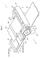
- Fig. 1 is a perspective view showing an intermittent cutting transferring device 1 according to the first embodiment.
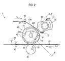
- Fig. 2 is a side view (view on arrow A of Fig. 1 ) showing the intermittent cutting transferring device 1 according to the first embodiment.
- the intermittent cutting transferring device 1 is configured to intermittently transfer a cut film sheet 10, obtained by cutting a continuum of cut film sheet 10A printed with patterns such as characters and figures, to a web 20 being fed continuously.
- a length (L1) of the cut film sheet 10 in its moving direction (hereinafter called the "MD direction") is shorter than a length (L2) thereof in a direction crossing the MD direction (this direction is hereinafter called the "CD direction").
- the intermittent cutting transferring device 1 is configured briefly of an upper blade roll 30, a lower blade roll 40, and a transfer roll 50.
- Two blades 32 are provided on an outer peripheral surface 31 of the upper blade roll 30.
- the upper blade roll 30 rotates at a peripheral velocity (V 1 ) approximately equal to a peripheral velocity of the lower blade roll 40.
- the upper blade roll 30 rotates at the peripheral velocity (V 1 ) higher than a velocity (V 2 ) in which the continuum of film sheet 10A is fed to the lower blade roll 40 by a pair of driving rolls 60 and 61.
- the upper blade roll 30 rotates at the peripheral velocity (V 1 ) approximately equal to a feeding velocity (V 3 ) of the web 20 continuously fed by driving rolls 62 and 63, or rotates at the peripheral velocity (V 1 ) lower than the feeding velocity (V 3 ) of the web 20.
- the lower blade roll 40 rotates at the peripheral velocity (V 1 ) approximately equal to the peripheral velocity of the upper blade roll 30, in a direction opposite to the direction in which the upper blade roll 30 rotates.
- V 1 peripheral velocity
- the configuration of the lower blade roll 40 will be described later (see Fig. 3 ).
- the transfer roll 50 brings the web 20 continuously fed by the driving rolls 62 and 63 into contact with the lower blade roll 40.
- the transfer roll 50 rotates at a peripheral velocity (V 4 ) approximately equal to the feeding velocity (V 3 ) of the web 20.
- the transfer roll 50 rotates at the peripheral velocity (V 4 ) approximately equal to the peripheral velocity (V 1 ) of the upper blade roll 30 and the lower blade roll 40 described above, or rotates at the peripheral velocity (V 4 ) higher than the peripheral velocity (V 1 ) of the upper blade roll 30 and the lower blade roll 40.
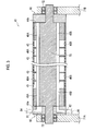
- Fig. 3 is a roll width direction sectional view (sectional view along B-B of Fig. 2 ) showing the lower blade roll 40 according to the first embodiment.
- the lower blade roll 40 is formed integrally with a roll shaft 70.
- the lower blade roll 40 is configured to be rotated between a pair of frames 71 A and 71 B by shaft bearings 72.
- Formed in the lower blade roll 40 are horizontal holes 45A and 45B penetrating from one end surface 44a to the other end surface 44b of the lower blade roll 40 and opening holes 46A and 46B connecting the horizontal holes 45A and 45B and suction holes 43.
- the suction holes 43 are formed at positions corresponding to the opening holes 46A and 46B.
- a suction member 80 is provided between the lower blade roll 40 and the one frame 71A, whereas a sealing member 90 is provided between the lower blade roll 40 and the other frame 71 B.
- the suction member 80 and the sealing member 90 each have a diameter approximately equal to the diameter of the lower blade roll 40, and are formed in a disk shape.
- the suction member 80 and the sealing member 90 are fixed to the frames 71A and 71 B, respectively, and are configured so as not to rotate together with the lower blade roll 40.
- the suction member 80 is provided with a first suction groove 81 which sucks the continuous film sheet 10A, a second suction groove 82 which sucks the cut film sheet 10 to guide the cut film sheet 10 to the web 20, and a transfer groove 83 for transferring, on the web 20, the cut film sheet 10 sucked onto the outer peripheral surface 41 of the lower blade roll 40.
- the first suction groove 81 is formed at a position corresponding to the horizontal hole 45A formed in the lower blade roll 40, and also to a portion of the outer peripheral surface 41 of the lower blade roll 40 around which the continuum of film sheet 10A is wound.
- the first suction groove 81 is connected with a suction connection pipe 84 connecting the first suction groove 81 and suction air supply means (not shown) which sucks air in the horizontal hole 45A.
- the second suction groove 82 is formed at a position corresponding to the horizontal hole 45B formed in the lower blade roll 40, and to a portion of the outer peripheral surface 41 of the lower blade roll 40 around which the cut film sheet 10 is wound.
- the second suction groove 82 is connected with a suction connection pipe 85 connecting the second suction groove 82 and suction air supply means (not shown) which sucks air in the horizontal hole 45B.
- the transfer groove 83 is formed at a position corresponding to the horizontal hole 45B formed in the lower blade roll 40, and to a portion to which the cut film sheet 10 is transferred.
- the transfer groove 83 is connected with a transfer connection pipe (not shown) connecting the transfer groove 83 and air releasing means (not shown) which releases the suction of air performed by the suction air supply means.
- the air releasing means does not necessarily need to release the suction of air performed by the suction air supply means, and may be configured to blow out air through the transfer groove 83 (transfer connection pipe).
- the suction member 80 is provided between the lower blade roll 40 and the one frame 71A.
- the suction member 80 may be additionally provided, instead of the sealing member 90, between the lower blade roll 40 and the other frame 71 B. That is, the suction air supply means may perform supply of air from both end sections of the horizontal holes 45A and 45B.
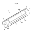
- Fig. 4 is a perspective view showing the lower blade roll 40 according to the first embodiment.
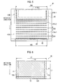
- Fig. 5 is a development view of the lower blade roll 40 according to the first embodiment.
- Fig. 6 is an upper view showing the cut film sheet according to the first embodiment.
- the suction holes 43 are formed in a first region 41A and in a second region 41 B on the outer peripheral surface 41 of the lower blade roll 40.
- the suction holes 43 are arranged at predetermined intervals in the roll peripheral direction and in the roll width direction, and are aligned such that the suction holes 43 that are adjacent in the roll peripheral direction are displaced from each other in the roll width direction (a so-called staggered alignment).
- the first region 41A is configured of suction regions 41A-1 each of which having the multiple suction holes 43 formed therein, and non-suction regions 41A-2 each of which having no suction hole 43 formed therein. Accordingly, the suction holding force in the suction regions 41A-1 is stronger than the suction holding force in the non-suction regions 41 A-2.
- the suction regions 41A-1 and the non-suction regions 41A-2 are provided in the roll width direction.
- the suction regions 41A-1 and the non-suction regions 41A-2 are provided alternately in the roll peripheral direction.
- Each of the regions 41A-1 is configured so that a width (W1) of the suction region 41A-1 in the roll peripheral direction can be shorter than a width (W2) of each non-suction region 41A-2 in the roll peripheral direction.
- Each of the regions 41A-1 is configured so that a width (W3) of the suction region 41A-1 in the roll width direction can be wider than the length (L2) of the cut film sheet 10 in the CD direction.
- the second region 41 B is configured of an edge area 41 B-1 having the multiple suction holes 43 formed therein, and a center area 41 B-2 having no suction hole 43 formed therein. Accordingly, the suction holding force in the edge area 41 B-1 is stronger than the suction holding force in the center area 41 B-2.
- the edge area 41 B-1 faces both side edge regions 11 and a front end region 12 formed ahead in the proceeding direction of the cut film sheet 10.
- the both side edge regions 11 of the cut film sheet 10 show regions within 25% of the length (L2) in the CD direction with both end sections 11A of the cut film sheet 10 as the references.
- the front end region 12 of the cut film sheet 10 formed ahead in the proceeding direction shows a region within 50% of the length (L1) in the MD direction with a front end section 12A of the cut film sheet as the reference.
- the area of the center area 41 B-2 needs to have an area that is 50% or more of a whole area of the cut film sheet 10.
- a maximum width (W4) of the edge area 41 B-1 in the roll width direction is approximately equivalent to the width (W3) of the suction region 41A-1 in the roll width direction described above, i.e., configured to be wider than the length (L2) of the cut film sheet 10 in the CD direction.
- the center area 41 B-2 faces a remaining region 13 which is a region other than the both side edge regions 11 and the front end region 12 formed ahead in the proceeding direction of the cut film sheet 10. Note that, as shown in Fig. 6 , the remaining region 13 shows a region inside the both side edge regions 11 and the front end region 12 formed ahead in the proceeding direction of the cut film sheet 10 described above.
- the intermittent cutting transferring device 1 guides the continuum of film sheet 10A between the blade 32 and the stationary blade 42 with the continuum of film sheet 10A being sucked onto the outer peripheral surface 41 of the lower blade roll 40 by the suction of the suction air supply means through the suction holes 43 formed in the first region 41A (suction region 41A-1) on the outer peripheral surface 41 of the lower blade roll 40.
- the continuum of film sheet 10A slides on the outer peripheral surface 41 of the lower blade roll 40 to be guided between the blade 32 and the stationary blade 42 because the upper blade roll 30 and the lower blade roll 40 rotate at the peripheral velocity (V 1 ) higher than the velocity (V 2 ) in which the continuum of film sheet 10A is fed to the lower blade roll 40.
- the intermittent cutting transferring device 1 intermittently cuts the continuum of film sheet 10A by bringing the blade 32 and the stationary blade 42 into contact with each other.
- the cut film sheet 10 is thus formed. Note that the length (L1) of the cut film sheet 10 in the MD direction is shorter than the length (L2) of the cut film sheet 10 in the CD direction.
- the intermittent cutting transferring device 1 guides the cut film sheet 10 to the web 20 while the cut film sheet 10 is being sucked onto the outer peripheral surface 41 of the lower blade roll 40 by the suction of the suction air supply means, through the suction holes 43 formed in the second region 41 B (edge area 41 B-1) on the outer peripheral surface 41 of the lower blade roll 40.
- the cut film sheet 10 is sucked onto the outer peripheral surface 41 of the lower blade roll 40 with the both side edge regions 11 and the front end region 12 formed ahead in the moving direction facing the edge area 41 B-1 of the second region 41 B as well as the remaining region 13 facing the center area 41 B-2 of the second region 41 B.
- the intermittent cutting transferring device 1 transfers the cut film sheet 10 sucked onto the outer side surface 41 of the lower blade roll 40 to the web 20 by releasing the suction of air performed by the suction air supply means.
- the suction holding force of the edge area 41B-1 is stronger than the suction holding force in the center area 41 B-2.
- the cut film sheet 10 comes into the suction holes 43 in less cases compared to the both side edge regions 11 and the front end region 12, whereby the formation of a wrinkle of the cut film sheet 10 can be suppressed. Moreover, the cut film sheet 10 is pulled toward the edge area 41 B-1 sides. Accordingly, even when the wrinkle is formed in the cut film sheet 10, the wrinkle formed in the cut film sheet 10 can be smoothed out in the remaining region 13 other than the both side edge regions 11 and the front end region 12.
- the air releasing means releases the suction of air performed by the suction air supply means, whereby the cut film sheet 10 makes contact on the web 20 firstly with the center area 41 B-2 having a weak suction holding force. That is, since the suction holding force in the center area 41 B-2 is weaker than the suction holding force in the edge area 41 B-1, it becomes easier to transfer the cut film sheet 10 to the web 20 from the center area 41B-2 having a weak suction holding force, as compared to the case where the suction holding force is the same in the entire region of the outer peripheral surface 41 of the lower blade roll 40. Thus, the formation of a wrinkle in the cut film sheet 10 can be suppressed.
- the intermittent cutting transferring device 1 has no suction hole 43 formed in the center area 41 B-2. Accordingly, at the time of the film feeding and the film transfer, the cut film sheet 10 is not sucked onto the outer peripheral surface 41 of the lower blade roll 40 in the center area 41 B-2, whereby the cut film sheet 10 does not come into the suction hole 43. Thus, the formation of a wrinkle in the cut film sheet 10 can be suppressed.
- the suction holding force in the edge area 41 B-1 is stronger than the suction holding force in the center area 41 B-2. Accordingly, the formation of a wrinkle in the cut film sheet 10 can be suppressed. Even when the wrinkle is formed in the cut film sheet 10, a wrinkle formed in the cut film sheet 10 can be smoothed out. Thus, it is particularly effective when the length (L1) of the cut film sheet 10 in the MD direction is shorter than the length (L2) in the CD direction.
- the intermittent cutting transferring device 1 is configured so that the maximum width (W4) of the edge area 41B-1 in the roll width direction is approximately equal to the width (W3) of the suction region 41A-1 in the roll width direction described above, or, in other words, so that the maximum width (W4) is wider than the length (L2) of the cut film sheet 10 in the CD direction. Accordingly, the both side edge regions 11 and the front end region 12 formed ahead in the proceeding direction of the cut film sheet 10 can reliably be sucked by the suction through the suction holes 43 formed in the edge area 41 B-1. Thus, at the time of transfer, the both side edge regions 11 and the front end region 12 formed ahead in the proceeding direction of the cut film sheet 10 can be prevented from being bent.
- the configuration of the intermittent cutting transferring device 1 according to a second embodiment will be described with reference to the drawings. Note that the same portions as those of the above-described intermittent cutting transferring device 1 according to the first embodiment are denoted by the same reference numerals, and differing portions will mainly be described.
- the first embodiment described above has no suction hole 43 formed in the center area 41 B-2.
- the suction holes 43 are formed in the center area 41 B-2.
- Fig. 7 is a roll width direction sectional view showing the lower blade roll 40 according to the second embodiment.
- the intermittent cutting transferring device 1 is configured so that at least one of the suction holding force in the edge area 41B-1 and the suction holding force in the center area 41 B-2 would be variable.
- the suction member 80 is provided also between the lower blade roll 40 and the other frame 71 B.
- a first horizontal hole 450A and a first opening hole 460A are formed in the lower blade roll 40.
- the first horizontal hole 450A penetrates from the one end surface 44a to the other end surface 44b of the lower blade roll 40, and the first opening hole 460A connects the first horizontal hole 450A and the suction holes 43 formed in the edge area 41 B-1.
- a second horizontal hole 450B and a second opening hole 460B are also formed in the lower blade roll 40.
- the second horizontal hole 450B extends approximately in parallel to the first horizontal hole 450A and penetrates from the one end surface 44a to the other end surface 44b of the lower blade roll 40, and the second opening hole 460B connects the second horizontal hole 450B and the suction holes 43 formed in the center area 41 B-2.
- the first horizontal hole 450A is connected to suction air supply means (not shown) through a first suction groove 81 A and a suction connection pipe 84A.
- the second horizontal hole 450B is connected to suction air supply means (not shown), which is provided separately from the suction air supply means connected with the first horizontal hole 450A, through a first suction groove 81B and a suction connection pipe 84B.
- a third horizontal hole 451A and a third opening hole 461A are provided in the lower blade roll 40.
- the third horizontal hole 451A penetrates from the one end surface 44a to the other end surface 44b of the lower blade roll 40, and the third opening hole 461A connects the third horizontal hole 451 A and the suction holes 43 formed in the edge area 41 B-1.
- a fourth horizontal hole 451 B and a fourth opening hole 461 B are also formed in the lower blade roll 40.
- the fourth horizontal hole 451 B extends approximately in parallel to the third horizontal hole 451A and penetrates from the one end surface 44a to the other end surface 44b of the lower blade roll 40, and the fourth opening hole 461 B connects the fourth horizontal hole 451 B and the suction holes 43 formed in the center area 41B-2.
- the third horizontal hole 451A is connected to suction air supply means (not shown) through a second suction groove 82A and a suction connection pipe 85A.
- the fourth horizontal hole 451 B is connected to suction air supply means (not shown), which is provided separately from the suction air supply means connected with the third horizontal hole 451A, through a second suction groove 82B and a suction connection pipe 85B.
- FIG. 8 is a development view showing the lower blade roll 40 according to the second embodiment.
- the suction holes 43 are formed in the entire region of the second region 41 B. Note that the suction holding force in the edge area 41B-1 is stronger than the suction holding force in the center area 41B-2.
- the suction holding force in the edge area 41 B-1 can be made stronger than the suction holding force in the center area 41 B-2.
- the suction force of the suction air supply means through the suction holes 43 in the edge area 41 B-1 is stronger than the suction force of the suction air supply means through the suction holes 43 formed in the center area 41 B-2.
- the aperture ratio of the suction holes 43 formed in the edge area 41 B-1 may be larger than the aperture ratio of the suction holes 43 formed in the center area 41 B-2.
- the edge area 41 B-1 and the center area 41 B-2 can be set in accordance with the size of the cut film sheet 10 (for example, the length (L2) of the cut film sheet 10 in the CD direction). Accordingly, the intermittent cutting transferring device 1 according to the second embodiment is able to manufacture the cut film sheet 10 in various sizes.
- two blades 32 are provided on the outer peripheral surface 31 of the upper blade roll 30.
- at least one blade 32 may be provided.
- at least one stationary blade 42 may be provided on the outer peripheral surface 41 of the lower blade roll 40.
- the first region 41A is configured of the suction region 41A-1 and the non-suction region 41A-2, but it is not limited thereto. It is needless to say that the suction holes 43 may be formed in the entire region.
- the present invention is useful in manufacturing method for an absorptive article since it is possible to provide an intermittent cutting transferring device, which can suppress the formation of a wrinkle in a film sheet and which can smooth out a wrinkle formed in the film sheet even when the wrinkle is formed in the film sheet.
Landscapes
- Engineering & Computer Science (AREA)
- Health & Medical Sciences (AREA)
- Life Sciences & Earth Sciences (AREA)
- Mechanical Engineering (AREA)
- Epidemiology (AREA)
- Public Health (AREA)
- Heart & Thoracic Surgery (AREA)
- Vascular Medicine (AREA)
- Manufacturing & Machinery (AREA)
- Animal Behavior & Ethology (AREA)
- General Health & Medical Sciences (AREA)
- Biomedical Technology (AREA)
- Veterinary Medicine (AREA)
- Forests & Forestry (AREA)
- Absorbent Articles And Supports Therefor (AREA)
- Perforating, Stamping-Out Or Severing By Means Other Than Cutting (AREA)
- Advancing Webs (AREA)
- Labeling Devices (AREA)
- Auxiliary Devices For And Details Of Packaging Control (AREA)
Abstract
Description
- The present invention relates to an intermittent cutting transferring device configured to cut a continuum of film sheet into film sheets and intermittently transfer the film sheets to a web being continuously fed.
- An intermittent cutting device is used in processes of manufacturing disposable diaper. Conventionally, the intermittent cutting device is configured to cut a continuum of film sheet, printed with patterns such as characters and figures, into the film sheets, and intermittently transfer the film sheets to a web being continuously fed.
- Generally, the film sheet is configured to have lower breathability, thinner thickness and more flexibility than the web. That is, the film sheets have characteristics of low rigidity and resilience.
- Such an intermittent cutting transferring device includes: an upper blade roll including blades on an outer peripheral surface; and a lower blade roll including, a stationary blade on an outer peripheral surface and a mesh suction plate over the entire outer peripheral surface (for example, see Patent document 1).
- The upper blade roll and the lower blade roll are configured to rotate at approximately the same peripheral velocity in directions opposite from each other. In addition, these rolls are also configured to rotate at peripheral velocities higher than the velocity in which the continuous film sheet is fed to the lower blade roll, and to rotate at peripheral velocities approximately equal to or lower than the feeding velocity of the web.
- Hereinafter, steps of intermittently transferring the film sheet to the web will be described using the intermittent cutting transferring device described above.
- In a first step, the intermittent cutting transferring device guides the continuum of film sheet between the blade and the stationary blade with the continuum of film sheet being sucked onto the outer peripheral surface of the lower blade roll by the suction through the mesh suction plate formed over the entire outer peripheral surface of the lower blade roll.
- At this time, the continuum of film sheet slides on the outer peripheral surface of the lower blade roll to be guided between the blade and the stationary blade since the upper blade roll and the lower blade roll rotate at the peripheral velocities higher than the velocity in which the continuous film sheet is fed to the lower blade roll.
- In a second step, the intermittent cutting transferring device intermittently cuts the continuum of film sheet by bringing the blade and the stationary blade into contact with each other, and thus forms a film sheet.
- In a third step, the intermittent cutting transferring device guides the film sheet which is cut to the web while the film sheet which is cut is being sucked onto the outer peripheral surface of the lower blade roll by the suction through the mesh suction plate formed over the entire outer peripheral surface of the lower blade roll.
- In a fourth step, the intermittent cutting transferring device transfers, to the web, the film sheet which is cut and sucked onto the outer side surface of the lower blade roll.
-
Patent document 1; Japanese Patent Application Publication No.Hei 10-218471 Fig. 3 ) - However, the conventional intermittent cutting transferring device described above has the following problem. That is, with the conventional intermittent cutting transferring device, a wrinkle is formed in the film sheet which is cut due to conditions such as unevenness in weight (weight per unit area) of the film sheet, contact failure of the blade and the stationary blade, and occurrence of wear in the blade.
- Accordingly, the film sheet which is cut is transferred to the web with the wrinkle being formed in the film sheet. Particularly, since the film sheet which is cut has the characteristics of low rigidity and resilience, once the wrinkle is formed, the film sheet cannot be restored to its original state.
- Thus, the present invention has been made in view of such a situation, and has an object of providing an intermittent cutting transferring device which can suppress the formation of a wrinkle in a film sheet and which can smooth out a wrinkle formed in the film sheet even when the wrinkle is formed in the film sheet.
- To solve the above situation, the present invention comprises the following aspects. A first aspect is summarized as an intermittent cutting transferring device configured to cut a continuum of film sheet into film sheets and to intermittently transfer one of the film sheets which are cut, herein after referred to as "a cut film sheet", to a web being continuously fed. The intermittent cutting transferring device comprises an upper blade roll provided with at least one blade on its outer peripheral surface and a lower blade roll provided with at least one stationary blade on its outer peripheral surface and having a plurality of suction holes formed on the outer peripheral surface. The upper blade roll and the lower blade roll rotate at approximately the same peripheral velocity in directions opposite from each other, rotate at the peripheral velocities higher than a velocity in which the continuum of film sheet is fed to the lower blade roll, and rotate at the peripheral velocities approximately equal to or lower than a feeding velocity of the web. The continuum of film sheet is guided between the blade and the stationary blade with the continuum of film sheet being sucked onto the outer peripheral surface of the lower blade roll by a suction through the suction holes formed in a first region on the outer peripheral surface of the lower blade roll. The continuum of film sheet is intermittently cut by bringing the blade and the stationary blade into contact with each other, and forms the cut film sheet. The cut film sheet is guided and transferred to the web while the cut film sheet is being sucked onto the outer peripheral surface of the lower blade roll by a suction through the suction holes formed in a second region on the outer peripheral surface of the lower blade roll. The cut film sheet is sucked onto the outer peripheral surface of the lower blade roll at a position where both side edge regions of the cut film sheet and a front end region thereof in a proceeding direction face an edge area of the second region while a remaining region of the cut film sheet faces a center area in the second region. And a suction holding force in the edge area is stronger than a suction holding force in the center area.
- According to the present invention, the intermittent cutting transferring device can be provided which can suppress the formation of a wrinkle in the film sheet and smooth out a wrinkle formed in the film sheet even when the wrinkle is formed in the film sheet.
-
-
Fig. 1 is a perspective view showing an intermittentcutting transferring device 1 according to a first embodiment. -
Fig. 2 is a side view (view on arrow A ofFig. 1 ) showing the intermittentcutting transferring device 1 according to the first embodiment. -
Fig. 3 is a roll width direction sectional view (sectional view along B-B ofFig. 2 ) showing alower blade roll 40 according to the first embodiment. -
Fig. 4 is a perspective view showing thelower blade roll 40 according to the first embodiment. -
Fig. 5 is a development view showing thelower blade roll 40 according to the first embodiment. -
Fig. 6 is an upper view showing a cut film sheet according to the first embodiment. -
Fig. 7 is a roll width direction sectional view showing thelower blade roll 40 according to a second embodiment. -
Fig. 8 is a development view showing thelower blade roll 40 according to the second embodiment. - Hereinafter, one example of an intermittent cutting transferring device according to the present invention will be described with reference to the drawings. Note that, throughout the drawings, the same or similar portions are denoted by the same or similar reference numerals. However, the drawings are schematic, and it should be noted that the dimensional proportions and others are different from their actual values.
- Thus, specific dimensions and the like should be determined based on the descriptions given below. It is needless to say that the dimensional relationships and dimensional proportions may differ from one drawing to another in some parts.
- First, the configuration of the intermittent cutting transferring device according to a first embodiment will be described with reference to the drawings.
Fig. 1 is a perspective view showing an intermittentcutting transferring device 1 according to the first embodiment.Fig. 2 is a side view (view on arrow A ofFig. 1 ) showing the intermittentcutting transferring device 1 according to the first embodiment. - As shown in
Figs. 1 and2 , the intermittentcutting transferring device 1 is configured to intermittently transfer acut film sheet 10, obtained by cutting a continuum of cutfilm sheet 10A printed with patterns such as characters and figures, to aweb 20 being fed continuously. - Note that a length (L1) of the
cut film sheet 10 in its moving direction (hereinafter called the "MD direction") is shorter than a length (L2) thereof in a direction crossing the MD direction (this direction is hereinafter called the "CD direction"). - The intermittent
cutting transferring device 1 is configured briefly of anupper blade roll 30, alower blade roll 40, and atransfer roll 50. - Two
blades 32 are provided on an outerperipheral surface 31 of theupper blade roll 30. Theupper blade roll 30 rotates at a peripheral velocity (V1) approximately equal to a peripheral velocity of thelower blade roll 40. Theupper blade roll 30 rotates at the peripheral velocity (V1) higher than a velocity (V2) in which the continuum offilm sheet 10A is fed to thelower blade roll 40 by a pair ofdriving rolls upper blade roll 30 rotates at the peripheral velocity (V1) approximately equal to a feeding velocity (V3) of theweb 20 continuously fed bydriving rolls web 20. - In an outer
peripheral surface 41 of thelower blade roll 40, twostationary blades 42 are provided, andsuction holes 43 which suck the continuum offilm sheet 10A and thecut film sheet 10 are formed. Thelower blade roll 40 rotates at the peripheral velocity (V1) approximately equal to the peripheral velocity of theupper blade roll 30, in a direction opposite to the direction in which the upper blade roll 30 rotates. The configuration of thelower blade roll 40 will be described later (seeFig. 3 ). - The
transfer roll 50 brings theweb 20 continuously fed by thedriving rolls lower blade roll 40. Thetransfer roll 50 rotates at a peripheral velocity (V4) approximately equal to the feeding velocity (V3) of theweb 20. In other words, thetransfer roll 50 rotates at the peripheral velocity (V4) approximately equal to the peripheral velocity (V1) of theupper blade roll 30 and thelower blade roll 40 described above, or rotates at the peripheral velocity (V4) higher than the peripheral velocity (V1) of theupper blade roll 30 and thelower blade roll 40. - Next, the configuration of the
lower blade roll 40 described above will be described with reference to the drawings.Fig. 3 is a roll width direction sectional view (sectional view along B-B ofFig. 2 ) showing thelower blade roll 40 according to the first embodiment. - As shown in
Fig. 3 , thelower blade roll 40 is formed integrally with aroll shaft 70. Thelower blade roll 40 is configured to be rotated between a pair offrames shaft bearings 72. - Formed in the
lower blade roll 40 arehorizontal holes end surface 44a to theother end surface 44b of thelower blade roll 40 and openingholes horizontal holes - A
suction member 80 is provided between thelower blade roll 40 and the oneframe 71A, whereas a sealingmember 90 is provided between thelower blade roll 40 and theother frame 71 B. - The
suction member 80 and the sealingmember 90 each have a diameter approximately equal to the diameter of thelower blade roll 40, and are formed in a disk shape. Thesuction member 80 and the sealingmember 90 are fixed to theframes lower blade roll 40. - The
suction member 80 is provided with afirst suction groove 81 which sucks thecontinuous film sheet 10A, asecond suction groove 82 which sucks thecut film sheet 10 to guide thecut film sheet 10 to theweb 20, and atransfer groove 83 for transferring, on theweb 20, thecut film sheet 10 sucked onto the outerperipheral surface 41 of thelower blade roll 40. - The
first suction groove 81 is formed at a position corresponding to thehorizontal hole 45A formed in thelower blade roll 40, and also to a portion of the outerperipheral surface 41 of thelower blade roll 40 around which the continuum offilm sheet 10A is wound. Thefirst suction groove 81 is connected with asuction connection pipe 84 connecting thefirst suction groove 81 and suction air supply means (not shown) which sucks air in thehorizontal hole 45A. - The
second suction groove 82 is formed at a position corresponding to thehorizontal hole 45B formed in thelower blade roll 40, and to a portion of the outerperipheral surface 41 of thelower blade roll 40 around which thecut film sheet 10 is wound. Thesecond suction groove 82 is connected with asuction connection pipe 85 connecting thesecond suction groove 82 and suction air supply means (not shown) which sucks air in thehorizontal hole 45B. - The
transfer groove 83 is formed at a position corresponding to thehorizontal hole 45B formed in thelower blade roll 40, and to a portion to which thecut film sheet 10 is transferred. Thetransfer groove 83 is connected with a transfer connection pipe (not shown) connecting thetransfer groove 83 and air releasing means (not shown) which releases the suction of air performed by the suction air supply means. - Note that the air releasing means does not necessarily need to release the suction of air performed by the suction air supply means, and may be configured to blow out air through the transfer groove 83 (transfer connection pipe).
- In this embodiment, the
suction member 80 is provided between thelower blade roll 40 and the oneframe 71A. However, it is not limited to this configuration, and thesuction member 80 may be additionally provided, instead of the sealingmember 90, between thelower blade roll 40 and the other frame 71 B. That is, the suction air supply means may perform supply of air from both end sections of thehorizontal holes - Next, the alignment of suction holes 43 provided in the
lower blade roll 40 described above will be described with reference to the drawings.Fig. 4 is a perspective view showing thelower blade roll 40 according to the first embodiment.Fig. 5 is a development view of thelower blade roll 40 according to the first embodiment.Fig. 6 is an upper view showing the cut film sheet according to the first embodiment. - As shown in
Figs. 4 and5 , the suction holes 43 are formed in afirst region 41A and in asecond region 41 B on the outerperipheral surface 41 of thelower blade roll 40. In thefirst region 41A and in thesecond region 41 B, the suction holes 43 are arranged at predetermined intervals in the roll peripheral direction and in the roll width direction, and are aligned such that the suction holes 43 that are adjacent in the roll peripheral direction are displaced from each other in the roll width direction (a so-called staggered alignment). - The
first region 41A is configured ofsuction regions 41A-1 each of which having the multiple suction holes 43 formed therein, andnon-suction regions 41A-2 each of which having nosuction hole 43 formed therein. Accordingly, the suction holding force in thesuction regions 41A-1 is stronger than the suction holding force in thenon-suction regions 41 A-2. - The
suction regions 41A-1 and thenon-suction regions 41A-2 are provided in the roll width direction. Thesuction regions 41A-1 and thenon-suction regions 41A-2 are provided alternately in the roll peripheral direction. - Each of the
regions 41A-1 is configured so that a width (W1) of thesuction region 41A-1 in the roll peripheral direction can be shorter than a width (W2) of eachnon-suction region 41A-2 in the roll peripheral direction. - Each of the
regions 41A-1 is configured so that a width (W3) of thesuction region 41A-1 in the roll width direction can be wider than the length (L2) of thecut film sheet 10 in the CD direction. - The
second region 41 B is configured of anedge area 41 B-1 having the multiple suction holes 43 formed therein, and acenter area 41 B-2 having nosuction hole 43 formed therein. Accordingly, the suction holding force in theedge area 41 B-1 is stronger than the suction holding force in thecenter area 41 B-2. - The
edge area 41 B-1 faces bothside edge regions 11 and afront end region 12 formed ahead in the proceeding direction of thecut film sheet 10. - As shown in
Fig. 6 , the bothside edge regions 11 of thecut film sheet 10 show regions within 25% of the length (L2) in the CD direction with bothend sections 11A of thecut film sheet 10 as the references. Thefront end region 12 of thecut film sheet 10 formed ahead in the proceeding direction shows a region within 50% of the length (L1) in the MD direction with afront end section 12A of the cut film sheet as the reference. Note that the area of thecenter area 41 B-2 needs to have an area that is 50% or more of a whole area of thecut film sheet 10. - A maximum width (W4) of the
edge area 41 B-1 in the roll width direction is approximately equivalent to the width (W3) of thesuction region 41A-1 in the roll width direction described above, i.e., configured to be wider than the length (L2) of thecut film sheet 10 in the CD direction. - The
center area 41 B-2 faces a remainingregion 13 which is a region other than the bothside edge regions 11 and thefront end region 12 formed ahead in the proceeding direction of thecut film sheet 10. Note that, as shown inFig. 6 , the remainingregion 13 shows a region inside the bothside edge regions 11 and thefront end region 12 formed ahead in the proceeding direction of thecut film sheet 10 described above. - Next, the operation of the intermittent
cutting transferring device 1 according to the first embodiment will be described briefly. - In a first step, the intermittent
cutting transferring device 1 guides the continuum offilm sheet 10A between theblade 32 and thestationary blade 42 with the continuum offilm sheet 10A being sucked onto the outerperipheral surface 41 of thelower blade roll 40 by the suction of the suction air supply means through the suction holes 43 formed in thefirst region 41A (suction region 41A-1) on the outerperipheral surface 41 of thelower blade roll 40. - At this time, the continuum of
film sheet 10A slides on the outerperipheral surface 41 of thelower blade roll 40 to be guided between theblade 32 and thestationary blade 42 because theupper blade roll 30 and thelower blade roll 40 rotate at the peripheral velocity (V1) higher than the velocity (V2) in which the continuum offilm sheet 10A is fed to thelower blade roll 40. - In a second step, the intermittent
cutting transferring device 1 intermittently cuts the continuum offilm sheet 10A by bringing theblade 32 and thestationary blade 42 into contact with each other. Thecut film sheet 10 is thus formed. Note that the length (L1) of thecut film sheet 10 in the MD direction is shorter than the length (L2) of thecut film sheet 10 in the CD direction. - In a third step, the intermittent
cutting transferring device 1 guides thecut film sheet 10 to theweb 20 while thecut film sheet 10 is being sucked onto the outerperipheral surface 41 of thelower blade roll 40 by the suction of the suction air supply means, through the suction holes 43 formed in thesecond region 41 B (edge area 41 B-1) on the outerperipheral surface 41 of thelower blade roll 40. - That is, the
cut film sheet 10 is sucked onto the outerperipheral surface 41 of thelower blade roll 40 with the bothside edge regions 11 and thefront end region 12 formed ahead in the moving direction facing theedge area 41 B-1 of thesecond region 41 B as well as the remainingregion 13 facing thecenter area 41 B-2 of thesecond region 41 B. - In a fourth step, the intermittent
cutting transferring device 1 transfers thecut film sheet 10 sucked onto theouter side surface 41 of thelower blade roll 40 to theweb 20 by releasing the suction of air performed by the suction air supply means. - In the intermittent
cutting transferring device 1 according to the first embodiment, the suction holding force of theedge area 41B-1 is stronger than the suction holding force in thecenter area 41 B-2. On this assumption, the operation and effect achieved until thecut film sheet 10 is guided to the web 20 (at the time of film feeding) will first be described. - In the remaining
region 13 other than the bothside edge regions 11 and thefront end region 12, thecut film sheet 10 comes into the suction holes 43 in less cases compared to the bothside edge regions 11 and thefront end region 12, whereby the formation of a wrinkle of thecut film sheet 10 can be suppressed. Moreover, thecut film sheet 10 is pulled toward theedge area 41 B-1 sides. Accordingly, even when the wrinkle is formed in thecut film sheet 10, the wrinkle formed in thecut film sheet 10 can be smoothed out in the remainingregion 13 other than the bothside edge regions 11 and thefront end region 12. - Next, the operation and effect achieved when the
cut film sheet 10 is transferred to the web 20 (at the time of film transfer) will be described. - When the
cut film sheet 10 makes contact on theweb 20 firstly with thefront end region 12. At this time, the air releasing means releases the suction of air performed by the suction air supply means, whereby thecut film sheet 10 makes contact on theweb 20 firstly with thecenter area 41 B-2 having a weak suction holding force. That is, since the suction holding force in thecenter area 41 B-2 is weaker than the suction holding force in theedge area 41 B-1, it becomes easier to transfer thecut film sheet 10 to theweb 20 from thecenter area 41B-2 having a weak suction holding force, as compared to the case where the suction holding force is the same in the entire region of the outerperipheral surface 41 of thelower blade roll 40. Thus, the formation of a wrinkle in thecut film sheet 10 can be suppressed. - The intermittent
cutting transferring device 1 according to the first embodiment has nosuction hole 43 formed in thecenter area 41 B-2. Accordingly, at the time of the film feeding and the film transfer, thecut film sheet 10 is not sucked onto the outerperipheral surface 41 of thelower blade roll 40 in thecenter area 41 B-2, whereby thecut film sheet 10 does not come into thesuction hole 43. Thus, the formation of a wrinkle in thecut film sheet 10 can be suppressed. - Note that, when the length (L1) of the
cut film sheet 10 in the MD direction is shorter than the length (L2) in the CD direction, the weight of the cut film sheet easily becomes uneven, and a wrinkle is easily formed in thecut film sheet 10 by a contact failure of the blade and the stationary blade or a wear of the blade. - On the other hand, in the intermittent
cutting transferring device 1 according to the first embodiment, as described above, the suction holding force in theedge area 41 B-1 is stronger than the suction holding force in thecenter area 41 B-2. Accordingly, the formation of a wrinkle in thecut film sheet 10 can be suppressed. Even when the wrinkle is formed in thecut film sheet 10, a wrinkle formed in thecut film sheet 10 can be smoothed out. Thus, it is particularly effective when the length (L1) of thecut film sheet 10 in the MD direction is shorter than the length (L2) in the CD direction. - The intermittent
cutting transferring device 1 according to the first embodiment is configured so that the maximum width (W4) of theedge area 41B-1 in the roll width direction is approximately equal to the width (W3) of thesuction region 41A-1 in the roll width direction described above, or, in other words, so that the maximum width (W4) is wider than the length (L2) of thecut film sheet 10 in the CD direction. Accordingly, the bothside edge regions 11 and thefront end region 12 formed ahead in the proceeding direction of thecut film sheet 10 can reliably be sucked by the suction through the suction holes 43 formed in theedge area 41 B-1. Thus, at the time of transfer, the bothside edge regions 11 and thefront end region 12 formed ahead in the proceeding direction of thecut film sheet 10 can be prevented from being bent. - Hereinafter, the configuration of the intermittent
cutting transferring device 1 according to a second embodiment will be described with reference to the drawings. Note that the same portions as those of the above-described intermittentcutting transferring device 1 according to the first embodiment are denoted by the same reference numerals, and differing portions will mainly be described. - Specifically, the first embodiment described above has no
suction hole 43 formed in thecenter area 41 B-2. In contrast, in the second embodiment, the suction holes 43 are formed in thecenter area 41 B-2. - First, the configuration of the
lower blade roll 40 according to the second embodiment will be described with reference to the drawing.Fig. 7 is a roll width direction sectional view showing thelower blade roll 40 according to the second embodiment. - As shown in
Fig. 7 , the intermittentcutting transferring device 1 is configured so that at least one of the suction holding force in theedge area 41B-1 and the suction holding force in thecenter area 41 B-2 would be variable. - In addition to that between the
lower blade roll 40 and the oneframe 71A, thesuction member 80 is provided also between thelower blade roll 40 and theother frame 71 B. - A first
horizontal hole 450A and afirst opening hole 460A are formed in thelower blade roll 40. The firsthorizontal hole 450A penetrates from the oneend surface 44a to theother end surface 44b of thelower blade roll 40, and thefirst opening hole 460A connects the firsthorizontal hole 450A and the suction holes 43 formed in theedge area 41 B-1. - In addition, a second
horizontal hole 450B and asecond opening hole 460B are also formed in thelower blade roll 40. The secondhorizontal hole 450B extends approximately in parallel to the firsthorizontal hole 450A and penetrates from the oneend surface 44a to theother end surface 44b of thelower blade roll 40, and thesecond opening hole 460B connects the secondhorizontal hole 450B and the suction holes 43 formed in thecenter area 41 B-2. - The first
horizontal hole 450A is connected to suction air supply means (not shown) through afirst suction groove 81 A and asuction connection pipe 84A. The secondhorizontal hole 450B is connected to suction air supply means (not shown), which is provided separately from the suction air supply means connected with the firsthorizontal hole 450A, through afirst suction groove 81B and asuction connection pipe 84B. - Further, a third
horizontal hole 451A and athird opening hole 461A are provided in thelower blade roll 40. The thirdhorizontal hole 451A penetrates from the oneend surface 44a to theother end surface 44b of thelower blade roll 40, and thethird opening hole 461A connects the thirdhorizontal hole 451 A and the suction holes 43 formed in theedge area 41 B-1. - In addition, a fourth
horizontal hole 451 B and afourth opening hole 461 B are also formed in thelower blade roll 40. The fourthhorizontal hole 451 B extends approximately in parallel to the thirdhorizontal hole 451A and penetrates from the oneend surface 44a to theother end surface 44b of thelower blade roll 40, and thefourth opening hole 461 B connects the fourthhorizontal hole 451 B and the suction holes 43 formed in thecenter area 41B-2. - The third
horizontal hole 451A is connected to suction air supply means (not shown) through asecond suction groove 82A and asuction connection pipe 85A. The fourthhorizontal hole 451 B is connected to suction air supply means (not shown), which is provided separately from the suction air supply means connected with the thirdhorizontal hole 451A, through asecond suction groove 82B and asuction connection pipe 85B. - Next, the alignment of the suction holes 43 according to the second embodiment will be described with reference to the drawing.
Fig. 8 is a development view showing thelower blade roll 40 according to the second embodiment. - As shown in
Fig. 8 , the suction holes 43 are formed in the entire region of thesecond region 41 B. Note that the suction holding force in theedge area 41B-1 is stronger than the suction holding force in thecenter area 41B-2. - That is, since the suction force of the suction air supply means through the suction holes 43 formed in the
edge area 41 B-1 is stronger than the suction force of the suction air supply means through the suction holes 43 formed in thecenter area 41 B-2, the suction holding force in theedge area 41 B-1 can be made stronger than the suction holding force in thecenter area 41 B-2. - In the description of the above second embodiment, the suction force of the suction air supply means through the suction holes 43 in the
edge area 41 B-1 is stronger than the suction force of the suction air supply means through the suction holes 43 formed in thecenter area 41 B-2. Note, however, that it is not limited thereto, and the aperture ratio of the suction holes 43 formed in theedge area 41 B-1 may be larger than the aperture ratio of the suction holes 43 formed in thecenter area 41 B-2. - In addition to the operation and effect of the first embodiment described above, in the intermittent
cutting transferring device 1 according to the second embodiment, theedge area 41 B-1 and thecenter area 41 B-2 can be set in accordance with the size of the cut film sheet 10 (for example, the length (L2) of thecut film sheet 10 in the CD direction). Accordingly, the intermittentcutting transferring device 1 according to the second embodiment is able to manufacture thecut film sheet 10 in various sizes. - As described above, the content of the present invention has been disclosed through the embodiments of the present invention, but the descriptions and drawings forming a part of the disclosure should not be construed to limit the present invention.
- In the embodiments, two
blades 32 are provided on the outerperipheral surface 31 of theupper blade roll 30. However, it is not limited thereto, and at least oneblade 32 may be provided. In the same manner, at least onestationary blade 42 may be provided on the outerperipheral surface 41 of thelower blade roll 40. - In the embodiments, the
first region 41A is configured of thesuction region 41A-1 and thenon-suction region 41A-2, but it is not limited thereto. It is needless to say that the suction holes 43 may be formed in the entire region. - Various alternative embodiments, examples, and application technology will become clear to those skilled in the art from this disclosure. Thus, the technical scope of the present invention is defined only by the claims appropriate from the descriptions above.
- Note that the entire contents of Japanese Patent Application No.
2008-171895 (filed on June 30, 2008 - The present invention is useful in manufacturing method for an absorptive article since it is possible to provide an intermittent cutting transferring device, which can suppress the formation of a wrinkle in a film sheet and which can smooth out a wrinkle formed in the film sheet even when the wrinkle is formed in the film sheet.
Claims (4)
- An intermittent cutting transferring device configured to cut a continuum of film sheet into film sheets and to intermittently transfer the film sheets to a web being continuously fed comprising:an upper blade roll including at least one blade on an outer peripheral surface; anda lower blade roll including, on an outer peripheral surface, at least one stationary blade and a plurality of suction holes, whereinthe upper blade roll and the lower blade roll rotate at approximately the same peripheral velocity in directions opposite from each other, rotate at the peripheral velocities higher than a velocity in which the continuum of film sheet is fed to the lower blade roll, and rotate at the peripheral velocities approximately equal to or lower than a feeding velocity of the web,the continuum of film sheet is guided between the blade and the stationary blade while the continuum of film sheet is being sucked onto the outer peripheral surface of the lower blade roll by a suction through the suction holes formed in a first region on the outer peripheral surface of the lower blade roll,the continuum of film sheet is intermittently cut by bringing the blade and the stationary blade into contact with each other, and form a film sheet,the film sheet which is cut is guided and transferred to the web while the film sheet which is cut is being sucked onto the outer peripheral surface of the lower blade roll by a suction through the suction holes formed in a second region on the outer peripheral surface of the lower blade roll,the film sheet which is cut is sucked onto the outer peripheral surface of the lower blade roll at a position where both side edge regions of the film sheet which is cut and a front end region of the film sheet which is cut in a moving face an edge area of the second region while a remaining region of the film sheet which is cut faces a center area in the second region, anda suction holding force in the edge area is stronger than a suction holding force in the center area.
- The intermittent cutting transferring device according to claim 1, wherein the suction hole is not formed in the center area.
- The intermittent cutting transferring device according to claim 1, wherein at least one of the suction holding force in the edge area and the suction holding force in the center area is variable.
- The intermittent cutting transferring device according to any one of claims 1-3, wherein a length of the film sheet which is cut in a moving direction is shorter than a length of the film sheet which is cut in a direction crossing the moving direction.
Applications Claiming Priority (2)
| Application Number | Priority Date | Filing Date | Title |
|---|---|---|---|
| JP2008171894A JP5123760B2 (en) | 2008-06-30 | 2008-06-30 | Intermittent cutting transfer device |
| PCT/JP2009/061920 WO2010001881A1 (en) | 2008-06-30 | 2009-06-30 | Intermittent cutting and transfer device |
Publications (3)
| Publication Number | Publication Date |
|---|---|
| EP2301875A1 true EP2301875A1 (en) | 2011-03-30 |
| EP2301875A4 EP2301875A4 (en) | 2011-10-05 |
| EP2301875B1 EP2301875B1 (en) | 2013-07-03 |
Family
ID=41445992
Family Applications (1)
| Application Number | Title | Priority Date | Filing Date |
|---|---|---|---|
| EP20090773459 Not-in-force EP2301875B1 (en) | 2008-06-30 | 2009-06-30 | Intermittent cutting and transfer device |
Country Status (8)
| Country | Link |
|---|---|
| US (2) | US8276638B2 (en) |
| EP (1) | EP2301875B1 (en) |
| JP (1) | JP5123760B2 (en) |
| CN (1) | CN102076585B (en) |
| AR (1) | AR072417A1 (en) |
| RU (1) | RU2402479C2 (en) |
| TW (1) | TW201008860A (en) |
| WO (1) | WO2010001881A1 (en) |
Cited By (1)
| Publication number | Priority date | Publication date | Assignee | Title |
|---|---|---|---|---|
| EP2374437A4 (en) * | 2008-12-18 | 2013-05-01 | Uni Charm Corp | Method and device for manufacturing composite element consisting of sheet-like members and adapted for use in absorptive article |
Families Citing this family (22)
| Publication number | Priority date | Publication date | Assignee | Title |
|---|---|---|---|---|
| US9550306B2 (en) | 2007-02-21 | 2017-01-24 | Curt G. Joa, Inc. | Single transfer insert placement and apparatus with cross-direction insert placement control |
| US9944487B2 (en) | 2007-02-21 | 2018-04-17 | Curt G. Joa, Inc. | Single transfer insert placement method and apparatus |
| JP5123760B2 (en) | 2008-06-30 | 2013-01-23 | ユニ・チャーム株式会社 | Intermittent cutting transfer device |
| WO2011012926A1 (en) * | 2009-07-29 | 2011-02-03 | Sidel S.P.A. | Cutting unit for labelling machines |
| US9902083B2 (en) | 2010-09-30 | 2018-02-27 | The Procter & Gamble Company | Absorbent article substrate trim material removal process and apparatus |
| EP2945871A1 (en) * | 2012-12-10 | 2015-11-25 | G. Mondini SpA | Sealing machine with no residual film waste |
| US8939445B2 (en) * | 2013-05-30 | 2015-01-27 | Kimberly-Clark Worldwide, Inc. | Vacuum roll with internal rotary valve |
| CN104720982B (en) * | 2015-02-27 | 2018-10-26 | 安庆市恒昌机械制造有限责任公司 | Sheet material cutting, transfer, complex method on drug sundries product line |
| EP3463774B1 (en) * | 2016-05-24 | 2022-10-05 | The Procter & Gamble Company | Rotary anvil |
| JP6829814B2 (en) * | 2017-03-13 | 2021-02-17 | 日本電気硝子株式会社 | Glass film manufacturing method |
| JP6976074B2 (en) * | 2017-04-26 | 2021-12-01 | 住友化学株式会社 | Manufacturing method of transport device and laminate |
| US10820499B2 (en) * | 2018-06-08 | 2020-11-03 | Cnh Industrial America Llc | Hybrid disc cutting system having a knife mount for an agricultural vehicle |
| CN109051974B (en) * | 2018-07-05 | 2023-10-31 | 山东钢铁股份有限公司 | A follow-up film online laying and cutting device |
| CN109550633A (en) * | 2018-12-17 | 2019-04-02 | 安徽迈德普斯医疗科技有限公司 | One kind covering adhesive dispenser to surgical paper |
| US11981043B2 (en) * | 2019-12-05 | 2024-05-14 | Sidel Participations | Cutting device for cutting labels from a web of labelling material |
| JP7736457B2 (en) * | 2021-05-31 | 2025-09-09 | 株式会社ディスコ | Sheet attachment device |
| CN113633468A (en) * | 2021-08-11 | 2021-11-12 | 中山佳健生活用品有限公司 | Process method for processing permeation gaps of sanitary towel core body on line |
| CN113712736A (en) * | 2021-08-30 | 2021-11-30 | 福建恒安集团有限公司 | Diversion layer short cutter mechanism with variable adsorption width |
| CN114248530B (en) * | 2021-12-30 | 2024-01-12 | 保定盛通建材科技开发有限公司 | Film laminating machine for aluminum-zinc plated plate |
| US11618177B1 (en) | 2022-04-12 | 2023-04-04 | Bradley W Boesel | Orbital knife |
| IT202200013189A1 (en) * | 2022-06-22 | 2023-12-22 | Fameccanica Data Spa | Procedure for the transverse cutting of a water-soluble tape |
| CN115418848B (en) * | 2022-09-23 | 2024-02-13 | 绍兴博利豪家纺有限公司 | High-efficient fabric cutting machine |
Family Cites Families (21)
| Publication number | Priority date | Publication date | Assignee | Title |
|---|---|---|---|---|
| SU42023A1 (en) * | 1933-11-02 | 1935-03-31 | А.В. Терещенко | Machine for cutting parts from fabric, rubber, etc. |
| US4016032A (en) * | 1972-11-30 | 1977-04-05 | Valmet Oy | Suction roll for transferring a web away from a press section |
| JPS5162847U (en) * | 1974-11-12 | 1976-05-18 | ||
| JPS59112010A (en) | 1982-12-15 | 1984-06-28 | ユニ・チャ−ム株式会社 | Disposable sanitary article and attachment of elastic memberthereto |
| SU1743890A1 (en) * | 1988-12-12 | 1992-06-30 | Предприятие П/Я В-8996 | Device for cutting fine-sheet reel material |
| JP2709168B2 (en) * | 1989-12-25 | 1998-02-04 | 株式会社ナべヤ | Meandering prevention roll for cold strip |
| US5137758A (en) * | 1991-03-27 | 1992-08-11 | Minnesota Mining And Manufacturing Company | Apparatus and method for coating flexible sheets while inhibiting curl |
| RU2013199C1 (en) * | 1991-08-02 | 1994-05-30 | Акционерное общество "Белокалитвинское металлургическое производственное объединение" | Device for cutting strip into measured lengths |
| US5405487A (en) * | 1992-06-30 | 1995-04-11 | Cms Gilbreth Packaging Systems, Inc. | Apparatus and method for applying labels onto small cylindrical articles and web and adhesive delivery mechanism |
| CH688893A5 (en) * | 1994-05-11 | 1998-05-15 | De La Rue Giori Sa | Draw roller for transporting a material web, especially a paper web in a web printing machine. |
| JP3695875B2 (en) | 1997-02-04 | 2005-09-14 | 花王株式会社 | Intermittent cutting and transfer device for adhesive sheets |
| JP2000503585A (en) | 1997-03-19 | 2000-03-28 | ザ、プロクター、エンド、ギャンブル、カンパニー | Method of assembling web or film material using electrostatic charge |
| JP2000177897A (en) * | 1998-12-16 | 2000-06-27 | Toray Ind Inc | Suction roll and film conveyor |
| US6634269B2 (en) * | 2001-03-15 | 2003-10-21 | The Procter & Gamble Company | Apparatus and method for associating cut sheet sections with a moving carrier web |
| US6811019B2 (en) * | 2001-06-29 | 2004-11-02 | The Procter & Gamble Company | Method and apparatus utilizing servo motors for placing parts onto a moving web |
| CN1950568A (en) * | 2004-05-07 | 2007-04-18 | 沃依特专利有限责任公司 | Suction roll in a machine for producing a fibrous material web |
| US7618513B2 (en) * | 2005-05-31 | 2009-11-17 | Curt G. Joa, Inc. | Web stabilization on a slip and cut applicator |
| US7533709B2 (en) * | 2005-05-31 | 2009-05-19 | Curt G. Joa, Inc. | High speed vacuum porting |
| JP4726674B2 (en) * | 2006-03-29 | 2011-07-20 | 花王株式会社 | Sheet cutting method and apparatus |
| JP5022042B2 (en) | 2007-01-09 | 2012-09-12 | 欣興電子股▲分▼有限公司 | Laminated structure of semiconductor element embedded support substrate and manufacturing method thereof |
| JP5123760B2 (en) | 2008-06-30 | 2013-01-23 | ユニ・チャーム株式会社 | Intermittent cutting transfer device |
-
2008
- 2008-06-30 JP JP2008171894A patent/JP5123760B2/en not_active Expired - Fee Related
- 2008-08-22 RU RU2008134332A patent/RU2402479C2/en active
-
2009
- 2009-02-20 US US12/390,099 patent/US8276638B2/en not_active Expired - Fee Related
- 2009-06-29 TW TW98121824A patent/TW201008860A/en unknown
- 2009-06-30 CN CN2009801250196A patent/CN102076585B/en not_active Expired - Fee Related
- 2009-06-30 AR ARP090102431 patent/AR072417A1/en not_active Application Discontinuation
- 2009-06-30 EP EP20090773459 patent/EP2301875B1/en not_active Not-in-force
- 2009-06-30 WO PCT/JP2009/061920 patent/WO2010001881A1/en not_active Ceased
-
2012
- 2012-08-30 US US13/598,726 patent/US8789572B2/en not_active Expired - Fee Related
Cited By (2)
| Publication number | Priority date | Publication date | Assignee | Title |
|---|---|---|---|---|
| EP2374437A4 (en) * | 2008-12-18 | 2013-05-01 | Uni Charm Corp | Method and device for manufacturing composite element consisting of sheet-like members and adapted for use in absorptive article |
| US9248053B2 (en) | 2008-12-18 | 2016-02-02 | Unicharm Corporation | Manufacturing method and manufacturing equipment of composite body of sheet-like member of absorbent article |
Also Published As
| Publication number | Publication date |
|---|---|
| EP2301875B1 (en) | 2013-07-03 |
| JP5123760B2 (en) | 2013-01-23 |
| JP2010013195A (en) | 2010-01-21 |
| AR072417A1 (en) | 2010-08-25 |
| US8276638B2 (en) | 2012-10-02 |
| EP2301875A4 (en) | 2011-10-05 |
| US8789572B2 (en) | 2014-07-29 |
| CN102076585A (en) | 2011-05-25 |
| WO2010001881A1 (en) | 2010-01-07 |
| CN102076585B (en) | 2013-11-06 |
| US20120318111A1 (en) | 2012-12-20 |
| RU2008134332A (en) | 2010-02-27 |
| RU2402479C2 (en) | 2010-10-27 |
| TW201008860A (en) | 2010-03-01 |
| US20090321021A1 (en) | 2009-12-31 |
Similar Documents
| Publication | Publication Date | Title |
|---|---|---|
| EP2301875B1 (en) | Intermittent cutting and transfer device | |
| EP2301876B1 (en) | Intermittent cutting and transfer device | |
| WO2010051146A4 (en) | Two side cut reseal with pressure sensitive adhesive and the method for making same | |
| JP2006187817A (en) | Guillotine cutter and tape sticking device | |
| KR20120086708A (en) | Corrugated edge nip | |
| JP4524252B2 (en) | Method for manufacturing worn article | |
| CN215243550U (en) | Cutting device and FPC gum production line | |
| JP6220795B2 (en) | Manufacturing method and manufacturing apparatus for composite of continuous sheet according to absorbent article | |
| JP4942286B2 (en) | Cover strip | |
| JP3106008U (en) | Adhesive tape | |
| JPH11286357A (en) | Tab seals and tab seal continuities for preventing unraveling of web paper | |
| JP3785112B2 (en) | Perforated plastic sheet for bending | |
| JP2009220964A (en) | Web conveying device and web splicing method | |
| KR20250139980A (en) | Apparatus for Cutting Electrode Sheet | |
| JP5832720B2 (en) | Carton for wrap film | |
| JP6798175B2 (en) | Manufacturing method of printed matter with card paper and printed matter with card paper | |
| JPH11235759A (en) | Film suction device | |
| JP2003155150A (en) | Web tab and web tab tape and web | |
| HK1140741B (en) | A method and a unit for producing stamps applied to cigarette packets |
Legal Events
| Date | Code | Title | Description |
|---|---|---|---|
| PUAI | Public reference made under article 153(3) epc to a published international application that has entered the european phase |
Free format text: ORIGINAL CODE: 0009012 |
|
| 17P | Request for examination filed |
Effective date: 20110124 |
|
| AK | Designated contracting states |
Kind code of ref document: A1 Designated state(s): AT BE BG CH CY CZ DE DK EE ES FI FR GB GR HR HU IE IS IT LI LT LU LV MC MK MT NL NO PL PT RO SE SI SK TR |
|
| AX | Request for extension of the european patent |
Extension state: AL BA RS |
|
| RIN1 | Information on inventor provided before grant (corrected) |
Inventor name: YAMAMOTO, HIROKI |
|
| A4 | Supplementary search report drawn up and despatched |
Effective date: 20110906 |
|
| DAX | Request for extension of the european patent (deleted) | ||
| RIC1 | Information provided on ipc code assigned before grant |
Ipc: B65H 20/12 20060101ALI20110831BHEP Ipc: B65H 27/00 20060101ALI20110831BHEP Ipc: B65H 37/04 20060101AFI20110831BHEP Ipc: A61F 13/15 20060101ALI20110831BHEP Ipc: B65H 35/08 20060101ALI20110831BHEP Ipc: A61F 13/49 20060101ALI20110831BHEP |
|
| GRAP | Despatch of communication of intention to grant a patent |
Free format text: ORIGINAL CODE: EPIDOSNIGR1 |
|
| GRAS | Grant fee paid |
Free format text: ORIGINAL CODE: EPIDOSNIGR3 |
|
| GRAA | (expected) grant |
Free format text: ORIGINAL CODE: 0009210 |
|
| AK | Designated contracting states |
Kind code of ref document: B1 Designated state(s): AT BE BG CH CY CZ DE DK EE ES FI FR GB GR HR HU IE IS IT LI LT LU LV MC MK MT NL NO PL PT RO SE SI SK TR |
|
| REG | Reference to a national code |
Ref country code: GB Ref legal event code: FG4D |
|
| REG | Reference to a national code |
Ref country code: CH Ref legal event code: EP Ref country code: AT Ref legal event code: REF Ref document number: 619615 Country of ref document: AT Kind code of ref document: T Effective date: 20130715 |
|
| RAP2 | Party data changed (patent owner data changed or rights of a patent transferred) |
Owner name: UNICHARM CORPORATION |
|
| REG | Reference to a national code |
Ref country code: IE Ref legal event code: FG4D |
|
| REG | Reference to a national code |
Ref country code: DE Ref legal event code: R096 Ref document number: 602009016904 Country of ref document: DE Effective date: 20130829 |
|
| REG | Reference to a national code |
Ref country code: SE Ref legal event code: TRGR |
|
| REG | Reference to a national code |
Ref country code: NL Ref legal event code: T3 |
|
| PG25 | Lapsed in a contracting state [announced via postgrant information from national office to epo] |
Ref country code: SI Free format text: LAPSE BECAUSE OF FAILURE TO SUBMIT A TRANSLATION OF THE DESCRIPTION OR TO PAY THE FEE WITHIN THE PRESCRIBED TIME-LIMIT Effective date: 20130703 |
|
| REG | Reference to a national code |
Ref country code: AT Ref legal event code: MK05 Ref document number: 619615 Country of ref document: AT Kind code of ref document: T Effective date: 20130703 |
|
| REG | Reference to a national code |
Ref country code: LT Ref legal event code: MG4D |
|
| PG25 | Lapsed in a contracting state [announced via postgrant information from national office to epo] |
Ref country code: LT Free format text: LAPSE BECAUSE OF FAILURE TO SUBMIT A TRANSLATION OF THE DESCRIPTION OR TO PAY THE FEE WITHIN THE PRESCRIBED TIME-LIMIT Effective date: 20130703 Ref country code: NO Free format text: LAPSE BECAUSE OF FAILURE TO SUBMIT A TRANSLATION OF THE DESCRIPTION OR TO PAY THE FEE WITHIN THE PRESCRIBED TIME-LIMIT Effective date: 20131003 Ref country code: IS Free format text: LAPSE BECAUSE OF FAILURE TO SUBMIT A TRANSLATION OF THE DESCRIPTION OR TO PAY THE FEE WITHIN THE PRESCRIBED TIME-LIMIT Effective date: 20131103 Ref country code: CY Free format text: LAPSE BECAUSE OF FAILURE TO SUBMIT A TRANSLATION OF THE DESCRIPTION OR TO PAY THE FEE WITHIN THE PRESCRIBED TIME-LIMIT Effective date: 20130710 Ref country code: HR Free format text: LAPSE BECAUSE OF FAILURE TO SUBMIT A TRANSLATION OF THE DESCRIPTION OR TO PAY THE FEE WITHIN THE PRESCRIBED TIME-LIMIT Effective date: 20130703 Ref country code: PT Free format text: LAPSE BECAUSE OF FAILURE TO SUBMIT A TRANSLATION OF THE DESCRIPTION OR TO PAY THE FEE WITHIN THE PRESCRIBED TIME-LIMIT Effective date: 20131104 Ref country code: BE Free format text: LAPSE BECAUSE OF FAILURE TO SUBMIT A TRANSLATION OF THE DESCRIPTION OR TO PAY THE FEE WITHIN THE PRESCRIBED TIME-LIMIT Effective date: 20130703 Ref country code: AT Free format text: LAPSE BECAUSE OF FAILURE TO SUBMIT A TRANSLATION OF THE DESCRIPTION OR TO PAY THE FEE WITHIN THE PRESCRIBED TIME-LIMIT Effective date: 20130703 |
|
| PG25 | Lapsed in a contracting state [announced via postgrant information from national office to epo] |
Ref country code: LV Free format text: LAPSE BECAUSE OF FAILURE TO SUBMIT A TRANSLATION OF THE DESCRIPTION OR TO PAY THE FEE WITHIN THE PRESCRIBED TIME-LIMIT Effective date: 20130703 Ref country code: ES Free format text: LAPSE BECAUSE OF FAILURE TO SUBMIT A TRANSLATION OF THE DESCRIPTION OR TO PAY THE FEE WITHIN THE PRESCRIBED TIME-LIMIT Effective date: 20131014 Ref country code: PL Free format text: LAPSE BECAUSE OF FAILURE TO SUBMIT A TRANSLATION OF THE DESCRIPTION OR TO PAY THE FEE WITHIN THE PRESCRIBED TIME-LIMIT Effective date: 20130703 Ref country code: FI Free format text: LAPSE BECAUSE OF FAILURE TO SUBMIT A TRANSLATION OF THE DESCRIPTION OR TO PAY THE FEE WITHIN THE PRESCRIBED TIME-LIMIT Effective date: 20130703 Ref country code: GR Free format text: LAPSE BECAUSE OF FAILURE TO SUBMIT A TRANSLATION OF THE DESCRIPTION OR TO PAY THE FEE WITHIN THE PRESCRIBED TIME-LIMIT Effective date: 20131004 |
|
| PG25 | Lapsed in a contracting state [announced via postgrant information from national office to epo] |
Ref country code: CY Free format text: LAPSE BECAUSE OF FAILURE TO SUBMIT A TRANSLATION OF THE DESCRIPTION OR TO PAY THE FEE WITHIN THE PRESCRIBED TIME-LIMIT Effective date: 20130703 |
|
| PG25 | Lapsed in a contracting state [announced via postgrant information from national office to epo] |
Ref country code: CZ Free format text: LAPSE BECAUSE OF FAILURE TO SUBMIT A TRANSLATION OF THE DESCRIPTION OR TO PAY THE FEE WITHIN THE PRESCRIBED TIME-LIMIT Effective date: 20130703 Ref country code: RO Free format text: LAPSE BECAUSE OF FAILURE TO SUBMIT A TRANSLATION OF THE DESCRIPTION OR TO PAY THE FEE WITHIN THE PRESCRIBED TIME-LIMIT Effective date: 20130703 Ref country code: EE Free format text: LAPSE BECAUSE OF FAILURE TO SUBMIT A TRANSLATION OF THE DESCRIPTION OR TO PAY THE FEE WITHIN THE PRESCRIBED TIME-LIMIT Effective date: 20130703 Ref country code: DK Free format text: LAPSE BECAUSE OF FAILURE TO SUBMIT A TRANSLATION OF THE DESCRIPTION OR TO PAY THE FEE WITHIN THE PRESCRIBED TIME-LIMIT Effective date: 20130703 Ref country code: SK Free format text: LAPSE BECAUSE OF FAILURE TO SUBMIT A TRANSLATION OF THE DESCRIPTION OR TO PAY THE FEE WITHIN THE PRESCRIBED TIME-LIMIT Effective date: 20130703 |
|
| PLBE | No opposition filed within time limit |
Free format text: ORIGINAL CODE: 0009261 |
|
| STAA | Information on the status of an ep patent application or granted ep patent |
Free format text: STATUS: NO OPPOSITION FILED WITHIN TIME LIMIT |
|
| PG25 | Lapsed in a contracting state [announced via postgrant information from national office to epo] |
Ref country code: IT Free format text: LAPSE BECAUSE OF FAILURE TO SUBMIT A TRANSLATION OF THE DESCRIPTION OR TO PAY THE FEE WITHIN THE PRESCRIBED TIME-LIMIT Effective date: 20130703 |
|
| 26N | No opposition filed |
Effective date: 20140404 |
|
| REG | Reference to a national code |
Ref country code: DE Ref legal event code: R097 Ref document number: 602009016904 Country of ref document: DE Effective date: 20140404 |
|
| REG | Reference to a national code |
Ref country code: DE Ref legal event code: R119 Ref document number: 602009016904 Country of ref document: DE |
|
| REG | Reference to a national code |
Ref country code: NL Ref legal event code: V1 Effective date: 20150101 |
|
| PG25 | Lapsed in a contracting state [announced via postgrant information from national office to epo] |
Ref country code: LU Free format text: LAPSE BECAUSE OF FAILURE TO SUBMIT A TRANSLATION OF THE DESCRIPTION OR TO PAY THE FEE WITHIN THE PRESCRIBED TIME-LIMIT Effective date: 20140630 Ref country code: MC Free format text: LAPSE BECAUSE OF FAILURE TO SUBMIT A TRANSLATION OF THE DESCRIPTION OR TO PAY THE FEE WITHIN THE PRESCRIBED TIME-LIMIT Effective date: 20130703 |
|
| REG | Reference to a national code |
Ref country code: CH Ref legal event code: PL |
|
| GBPC | Gb: european patent ceased through non-payment of renewal fee |
Effective date: 20140630 |
|
| REG | Reference to a national code |
Ref country code: SE Ref legal event code: EUG |
|
| REG | Reference to a national code |
Ref country code: IE Ref legal event code: MM4A |
|
| REG | Reference to a national code |
Ref country code: DE Ref legal event code: R119 Ref document number: 602009016904 Country of ref document: DE Effective date: 20150101 |
|
| REG | Reference to a national code |
Ref country code: FR Ref legal event code: ST Effective date: 20150227 |
|
| PG25 | Lapsed in a contracting state [announced via postgrant information from national office to epo] |
Ref country code: NL Free format text: LAPSE BECAUSE OF NON-PAYMENT OF DUE FEES Effective date: 20150101 |
|
| PG25 | Lapsed in a contracting state [announced via postgrant information from national office to epo] |
Ref country code: DE Free format text: LAPSE BECAUSE OF NON-PAYMENT OF DUE FEES Effective date: 20150101 Ref country code: CH Free format text: LAPSE BECAUSE OF NON-PAYMENT OF DUE FEES Effective date: 20140630 Ref country code: LI Free format text: LAPSE BECAUSE OF NON-PAYMENT OF DUE FEES Effective date: 20140630 Ref country code: IE Free format text: LAPSE BECAUSE OF NON-PAYMENT OF DUE FEES Effective date: 20140630 |
|
| PG25 | Lapsed in a contracting state [announced via postgrant information from national office to epo] |
Ref country code: GB Free format text: LAPSE BECAUSE OF NON-PAYMENT OF DUE FEES Effective date: 20140630 Ref country code: FR Free format text: LAPSE BECAUSE OF NON-PAYMENT OF DUE FEES Effective date: 20140630 Ref country code: SE Free format text: LAPSE BECAUSE OF NON-PAYMENT OF DUE FEES Effective date: 20140701 |
|
| PG25 | Lapsed in a contracting state [announced via postgrant information from national office to epo] |
Ref country code: MT Free format text: LAPSE BECAUSE OF FAILURE TO SUBMIT A TRANSLATION OF THE DESCRIPTION OR TO PAY THE FEE WITHIN THE PRESCRIBED TIME-LIMIT Effective date: 20130703 |
|
| PG25 | Lapsed in a contracting state [announced via postgrant information from national office to epo] |
Ref country code: BG Free format text: LAPSE BECAUSE OF FAILURE TO SUBMIT A TRANSLATION OF THE DESCRIPTION OR TO PAY THE FEE WITHIN THE PRESCRIBED TIME-LIMIT Effective date: 20130703 |
|
| PG25 | Lapsed in a contracting state [announced via postgrant information from national office to epo] |
Ref country code: HU Free format text: LAPSE BECAUSE OF FAILURE TO SUBMIT A TRANSLATION OF THE DESCRIPTION OR TO PAY THE FEE WITHIN THE PRESCRIBED TIME-LIMIT; INVALID AB INITIO Effective date: 20090630 Ref country code: TR Free format text: LAPSE BECAUSE OF FAILURE TO SUBMIT A TRANSLATION OF THE DESCRIPTION OR TO PAY THE FEE WITHIN THE PRESCRIBED TIME-LIMIT Effective date: 20130703 |
|
| PG25 | Lapsed in a contracting state [announced via postgrant information from national office to epo] |
Ref country code: MK Free format text: LAPSE BECAUSE OF FAILURE TO SUBMIT A TRANSLATION OF THE DESCRIPTION OR TO PAY THE FEE WITHIN THE PRESCRIBED TIME-LIMIT Effective date: 20130703 |