EP2301022B1 - Multi-reference lpc filter quantization device and method - Google Patents
Multi-reference lpc filter quantization device and method Download PDFInfo
- Publication number
- EP2301022B1 EP2301022B1 EP09793770.0A EP09793770A EP2301022B1 EP 2301022 B1 EP2301022 B1 EP 2301022B1 EP 09793770 A EP09793770 A EP 09793770A EP 2301022 B1 EP2301022 B1 EP 2301022B1
- Authority
- EP
- European Patent Office
- Prior art keywords
- filter
- quantized
- lpc
- quantization
- lpc filter
- Prior art date
- Legal status (The legal status is an assumption and is not a legal conclusion. Google has not performed a legal analysis and makes no representation as to the accuracy of the status listed.)
- Active
Links
- 238000013139 quantization Methods 0.000 title claims description 197
- 238000000034 method Methods 0.000 title claims description 40
- 238000013213 extrapolation Methods 0.000 claims description 10
- 239000013598 vector Substances 0.000 description 145
- 101000959200 Lytechinus pictus Actin, cytoskeletal 2 Proteins 0.000 description 58
- 102100040006 Annexin A1 Human genes 0.000 description 22
- 101000959738 Homo sapiens Annexin A1 Proteins 0.000 description 22
- 101000929342 Lytechinus pictus Actin, cytoskeletal 1 Proteins 0.000 description 22
- 101000797296 Lytechinus pictus Actin, cytoskeletal 3 Proteins 0.000 description 21
- 230000006870 function Effects 0.000 description 14
- 230000003595 spectral effect Effects 0.000 description 11
- 238000010586 diagram Methods 0.000 description 9
- 230000005540 biological transmission Effects 0.000 description 8
- 230000005284 excitation Effects 0.000 description 8
- 230000008901 benefit Effects 0.000 description 7
- 239000000284 extract Substances 0.000 description 4
- 230000008569 process Effects 0.000 description 4
- 238000012545 processing Methods 0.000 description 4
- 230000009467 reduction Effects 0.000 description 4
- 230000005236 sound signal Effects 0.000 description 4
- 238000004364 calculation method Methods 0.000 description 3
- 230000011664 signaling Effects 0.000 description 3
- 238000004891 communication Methods 0.000 description 2
- 238000005070 sampling Methods 0.000 description 2
- 238000010187 selection method Methods 0.000 description 2
- 230000035945 sensitivity Effects 0.000 description 2
- 101100379142 Mus musculus Anxa1 gene Proteins 0.000 description 1
- 230000003044 adaptive effect Effects 0.000 description 1
- 238000013459 approach Methods 0.000 description 1
- 230000008859 change Effects 0.000 description 1
- 238000010276 construction Methods 0.000 description 1
- 230000001419 dependent effect Effects 0.000 description 1
- 230000000694 effects Effects 0.000 description 1
- 230000006872 improvement Effects 0.000 description 1
- 239000011159 matrix material Substances 0.000 description 1
- 238000005259 measurement Methods 0.000 description 1
- 238000001228 spectrum Methods 0.000 description 1
- 238000012360 testing method Methods 0.000 description 1
Images


Classifications
-
- G—PHYSICS
- G10—MUSICAL INSTRUMENTS; ACOUSTICS
- G10L—SPEECH ANALYSIS OR SYNTHESIS; SPEECH RECOGNITION; SPEECH OR VOICE PROCESSING; SPEECH OR AUDIO CODING OR DECODING
- G10L19/00—Speech or audio signals analysis-synthesis techniques for redundancy reduction, e.g. in vocoders; Coding or decoding of speech or audio signals, using source filter models or psychoacoustic analysis
- G10L19/04—Speech or audio signals analysis-synthesis techniques for redundancy reduction, e.g. in vocoders; Coding or decoding of speech or audio signals, using source filter models or psychoacoustic analysis using predictive techniques
- G10L19/06—Determination or coding of the spectral characteristics, e.g. of the short-term prediction coefficients
-
- H—ELECTRICITY
- H03—ELECTRONIC CIRCUITRY
- H03M—CODING; DECODING; CODE CONVERSION IN GENERAL
- H03M7/00—Conversion of a code where information is represented by a given sequence or number of digits to a code where the same, similar or subset of information is represented by a different sequence or number of digits
- H03M7/30—Compression; Expansion; Suppression of unnecessary data, e.g. redundancy reduction
- H03M7/3082—Vector coding
-
- G—PHYSICS
- G10—MUSICAL INSTRUMENTS; ACOUSTICS
- G10L—SPEECH ANALYSIS OR SYNTHESIS; SPEECH RECOGNITION; SPEECH OR VOICE PROCESSING; SPEECH OR AUDIO CODING OR DECODING
- G10L19/00—Speech or audio signals analysis-synthesis techniques for redundancy reduction, e.g. in vocoders; Coding or decoding of speech or audio signals, using source filter models or psychoacoustic analysis
- G10L19/04—Speech or audio signals analysis-synthesis techniques for redundancy reduction, e.g. in vocoders; Coding or decoding of speech or audio signals, using source filter models or psychoacoustic analysis using predictive techniques
- G10L19/16—Vocoder architecture
- G10L19/18—Vocoders using multiple modes
Definitions
- the present invention relates to coding and decoding of a sound signal, for example an audio signal. More specifically, the present invention relates to multi-reference LPC (Linear Predication Coefficients) filter quantization and inverse quantization device and method.
- LPC Linear Predication Coefficients
- a speech coder converts a speech signal into a digital bit stream which is transmitted over a communication channel or stored in a storage medium.
- the speech signal to be coded is digitized, that is sampled and quantized using for example 16-bits per sample.
- a challenge of the speech coder is to represent the digital samples with a smaller number of bits while maintaining a good subjective speech quality.
- a speech decoder or synthesizer converts the transmitted or stored bit stream back to a sound signal.
- CELP Code-Excited Linear Prediction
- the CELP coding technique is a basis for several speech coding standards both in wireless and wireline applications.
- the speech signal is sampled and processed in successive blocks of L samples usually called frames, where L is a predetermined number of samples corresponding typically to 10-30 ms of speech.
- a linear prediction (LP) filter is computed and transmitted every frame; the LP filter is also known as LPC (Linear Prediction Coefficients) filter.
- LPC Linear Prediction Coefficients
- the computation of the LPC filter typically uses a lookahead, for example a 5-15 ms speech segment from the subsequent frame.
- the L -sample frame is divided into smaller blocks called subframes.
- an excitation signal is usually obtained from two components, a past excitation and an innovative, fixed-codebook excitation.
- the past excitation is often referred to as the adaptive-codebook or pitch-codebook excitation.
- the parameters characterizing the excitation signal are coded and transmitted to the decoder, where the excitation signal is reconstructed and used as the input of the LPC filter.
- encoding models have been developed which combine a CELP coding optimized for speech signals with transform coding optimized for audio signals.
- An example of such models is the AMR-WB+ [1], which switches between CELP and TCX (Transform Coded eXcitation).
- AMR-WB+ a so-called super-frame is used which consists of four CELP frames (typically 80 ms).
- CELP coding parameters are transmitted once every 4 frames in AMR-WB+, quantization of the LPC filter is performed separately in each frame. Also, the LPC filter is quantized with a fixed number of bits per frame in the case of CELP frames.
- WO 2007/040349 A1 discloses a method and apparatus for signal processing. Therein data coding and encoding are performed with correlation and wherein grouping is used to increase coding efficiency. A signal received over an IP network is decapsulated and a pilot reference value corresponding to a plurality of data and a pilot difference value corresponding to the pilot reference value are determined. Data are then obtained using both values.
- US 5859932 A discloses a method to transmit and record an input pattern by dividing the input pattern into a vector quantization index and its difference signal.
- a multi-reference quantization device according to independent claim 1.
- Differential quantization with a choice between several possible references is used. More specifically, a LPC filter is differentially quantized relative to several possible references.
- LPC quantizers generally make use of prediction. Instead of quantizing the vector of Linear Prediction Coefficients (LPC vector) representing the LPC filter directly, a differential (or predictive) quantizer first computes a predicted value of this LPC vector and, then, quantizes the difference (often called prediction residual) between the original LPC vector and the predicted LPC vector.
- LPC vector Linear Prediction Coefficients
- Prediction is normally based on previous values of the LPC filter.
- Two types of predictors are commonly used: moving average (MA) and auto-regressive (AR) predictors.
- MA moving average
- AR auto-regressive predictors
- L2-norm mean square
- a differential (or predictive) quantizer can achieve the same degree of performance as an absolute quantizer but at a lower bit rate.
- a LPC filter differentially quantize a LPC filter relative to a reference, for example a reference filter, chosen among a number of possible references.
- the possible reference filters are already quantized past or future LPC filters (hence available at the decoder as at the encoder), or the results of various extrapolation or interpolation operations applied to already quantized past or future LPC filters.
- the reference filter that provides the lower distortion at a given rate, or the lower bit rate for a given target distortion level, is selected.
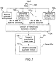
- Figure 1 is a block diagram illustrating a multi-reference LPC filter quantization device and method.
- a given LPC filter 101 represented by a vector of Linear Prediction Coefficients is inputted to the multi-reference LPC filter quantization device and method.
- the input LPC filter 101 is differentially quantized with respect to a reference chosen among a number of possible references 1, 2, ... , n . Possible references comprise:
- the input LPC filter 101 can be differentially quantized with respect to the previous quantized LPC filter, the following quantized LPC filter, or a mean value of those two previous and following quantized LPC filters.
- a reference can also be a LPC filter quantized using an absolute quantizer, or the result of any kind of interpolation, extrapolation or prediction (AR or MA) applied to already quantized LPC filters.
- the input LPC filter 101 is supplied to an absolute quantizer (Operation 102) and to differential quantizers (Operations 103 1 , 103 2 , ... , 103 n ).
- the absolute quantizer (Operation 102) quantizes the absolute value (not a difference) of the input LPC filter 101.
- the differential quantizers (Operations 103 1 , 103 2 , ... , 103 n ) are designed to differentially quantize the input LPC filter 101 with respect to respective references 1, 2,..., n.
- the multi-reference LPC filter quantization device and method of Figure 1 comprises a selector for selecting a reference amongst the references 1, 2, ..., n that provides the lowest distortion level at a given bit rate, or the lowest bit rate for a given target distortion level. More specifically, the selector (Operation 104) uses a selection criterion that minimizes the bit rate to achieve a certain target level of distortion, or that minimizes the level of distortion produced at a given bit rate.
- the selection of a reference amongst references 1, 2, ... , n to be actually used in the differential quantization process can be performed in closed-loop or in open-loop.
- closed-loop all possible references are tried and the reference that optimizes a certain criterion of distortion or bit rate is chosen.
- the closed-loop selection can be based on minimizing a weighted mean-squared error between the input LPC vector and the quantized LPC vector corresponding to each reference.
- the spectral distortion between the input LPC vector and the quantized LPC vector can be used.
- the quantization using the possible references can be performed while maintaining a distortion under a certain threshold, and the reference that both meets with this criterion and uses the smaller number of bits is chosen.
- variable bit rate algebraic vector quantizer can be used to quantize the scaled residual vector (difference between the input LPC vector and the reference) which uses a certain bit budget based on the energy of the scaled residual vector.
- the reference which yields the smaller number of bits is chosen.
- the selector of Operation 104 predetermines the reference based on the value of the Linear Prediction Coefficients of the input LPC filter to be quantized and of the Linear Prediction Coefficients of the available reference LPC filters. For example, the L2-norm of the residual vector is computed for all references and the reference that yields the smaller value is chosen.
- Operation 105 Following the selection of one of the references 1, 2, ... , n by the Operation 104, a transmitter (Operation 105) communicates or signals to the decoder (not shown) the quantized LPC filter (not shown) and an index indicative of the quantization mode (sub-operation 105 1 ), for example absolute or differential quantization. Also, when differential quantization is used, the transmitter (Operation 105) communicates or signals to the decoder indices representative of the selected reference and associated differential quantizer of Operations 103 1 , 103 2 , ... , 103 n (sub-operation 105 2 ). Some specific bits are transmitted to the decoder for such signaling.
- FIG. 1 illustrates an example of an absolute/differential scheme which selects between one absolute quantizer (Operation 102) and n differential quantizers (Operations 103 1 , 103 2 , ... , 103 n ) using respective, different references 1, 2, ... , n .
- the selection of a quantizer can be made by the selector of Operation 104 amongst the absolute and differential quantizers (Operations 102 and 103 1 , 103 2 , ... , 103 n ), wherein the selected quantizer will, according to the selection criterion, minimize the level of distortion produced at a given bit rate or minimize the bit rate to achieve a target level of distortion.
- LPC filters can be coded using the absolute quantizer (Operation 102).
- the other LPC filters are coded differentially with respect to one or several reference LPC filters in the differential quantizers (Operations 103 1 , 103 2 , ... , 103 n ) .
- the absolute quantizer (Operation 102) can be used as a safety-net solution for the otherwise differentially quantized LPC filters, for example in the case of large LPC deviations or when the absolute quantizer (Operation 102) is more efficient than the differential quantizers (Operations 103 1 , 103 2 , ... , 103 n ) in terms of bit rate.
- the reference LPC filter(s) can be all within the same super-frame to avoid introducing dependencies between super-frames which usually pose problems in case of transmission errors (packet losses or frame erasures).
- absolute quantization When differential quantization fails to achieve a target level of distortion, or when absolute quantization requires a smaller number of bits than differential quantization to achieve that level of distortion, absolute quantization is used as a safety-net solution.
- One or several bits, depending on the number of possible absolute and differential quantizers is (are) transmitted through the transmitter (Operation 105) to indicate to the decoder (not shown) the actual quantizer being used.
- Absolute / differential quantization combines the advantages of predictive quantization (reduction in bit rate associated with the reduction of the L2-norm of the data to be quantized) with the generality of absolute quantization (which is used as a safety-net in case differential (or predictive) quantization does not achieve a target, for example unnoticeable, level of distortion).
- differential quantizers When several differential quantizers (Operations 103 1 , 103 2 , ... , 103 n ) are included, these differential quantizers can make use of either a same predictor or different predictors. In particular, but not exclusively, these several differential quantizers can use the same prediction coefficients or different prediction coefficients.
- the decoder comprises means for receiving and extracting from the bit stream, for example a demultiplexer, (a) the quantized LPC filter and (b) the index (indices) or information:
- an absolute inverse quantizer (not shown) is provided for inverse quantizing the quantized LPC filter. If the information about the quantization mode indicates that the LPC filter has been quantized using differential quantization, a differential inverse quantizer (not shown) then differentially inverse quantizes the multi-reference differentially quantized LPC filter using the reference corresponding to the extracted reference information.
- the AMR-WB+ codec is a hybrid codec that switches between a time-domain coding model based on the ACELP coding scheme, and a transform-domain coding model called TCX.
- the AMR-WB+ proceeds as follows [1]:
- the combination of modes which minimizes a total weighted error is determined by a "closed-loop" mode selection procedure. More specifically, instead of testing the 26 combinations, the selection of the mode is performed through eleven (11) different trials (tree search, see Table 1). In AMR-WB+ codec, the closed-loop selection is based on minimizing the mean-squared error between the input and codec signal in a weighted domain (or maximizing the signal to quantization noise ratio).
- the LPC filters are one of the various parameters transmitted by the AMR-WB+ codec. Following are some key elements regarding the quantization and transmission of those LPC filters.
- the number of LPC filters transmitted to the decoder is the same for all coding modes and equal to 1. Only the LPC filter corresponding to the end of the covered segment is transmitted. More specifically, in the case of TCX1024, one (1) LPC filter is calculated and transmitted for a duration of four (4) frames. In the case of TCX512, one (1) LPC filter is calculated and transmitted for a duration of two (2) frames. In the case of TCX256 or ACELP, one (1) LPC filter is calculated and transmitted for the duration of one (1) frame.
- the AMR-WB+ codec uses a (first order moving-average) predictive LPC quantizer.
- the operation of the latter quantizer depends on the previously transmitted LPC filter, and consequently on the previously selected coding mode. Therefore, because the exact combination of modes is not known until the entire super-frame is coded, some LPC filters are encoded several times before the final combination of modes is determined.
- the LPC filter located at the end of frame 3 is transmitted to the decoder only when the third frame is encoded as ACELP or TCX256. It is not transmitted when frames 3 and 4 are jointly encoded using TCX512. With regards to the LPC filter located at the end of frame 2, it is transmitted in all combinations of modes except in TCX1024. Therefore, the prediction performed when quantizing the last LPC filter of the super-frame depends on the combination of modes for the whole super-frame.
- the principle of the disclosed technique is that the order in which the LPC filters are quantized is chosen so that, once the closed-loop decision is finalized, the quantization information corresponding to the unnecessary LPC filters can be skipped from the transmission with no effect on the way the other filters will be transmitted and decoded at the decoder. For each LPC filter to be quantized using the differential quantization strategy described above, this imposes some constraints on the possible reference LPC filters.
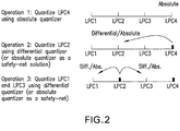
- Operation 1 of Figure 2 To avoid any inter super-frame dependencies, at least one LPC filter is quantized using an absolute LPC quantizer. Since filter LPC4 of frame 4 of the super-frame is always transmitted whatever the coding mode combination determined by the closed-loop selection procedure, it is convenient to quantize that filter LPC4 using an absolute quantizer.
- the next LPC filter to be quantized is filter LPC2 of frame 2 of the super-frame which is transmitted for all combinations of modes except for TCX1024.
- a differential quantizer can be used, for example to code the difference between filter LPC2 and the absolute quantized version of filter LPC4.
- the same absolute quantizer as used for coding filter LPC4 can also be used as a safety-net solution, for example in the case of large LPC deviations or when the absolute LPC quantizer is more efficient than the differential quantizer in terms of bit rate and/or level of distortion.
- Operation 3 of Figure 2 The remaining two LPC filters (filter LPC1 of frame 1 of the super-frame and filter LPC3 of frame 3 of the super-frame) are also quantized using the same differential/absolute quantization strategy. Both LPC filters can be quantized relative to the quantized version of filter LPC2.
- Figure 5 is a flow chart illustrating in more detail an example of an out-of-the-loop quantization scheme.
- Operation 501 An absolute quantizer quantizes the filter LPC4.
- Operation 512 is optional and used in a first LPC-based coding frame after a non-LPC-based coding frame.
- An absolute quantizer quantizes the filter LPC0 or a differential quantizer diffentially quantizes the filter LPC0 relative to the quantized filter LPC4.
- the filter LPC0 is the last LPC filter (LPC4) from the previous super-frame and can be used as a possible reference for quantizing the filters LPC1 to LPC4.
- Operation 503 An absolute quantizer quantizes the filter LPC2 or a differential quantizer diffentially quantizes the filter LPC2 relative to the quantized filter LPC4 used as reference.
- Operation 504 An absolute quantizer quantizes the filter LPC1, a differential quantizer diffentially quantizes the filter LPC1 relative to the quantized filter LPC2 used as reference, or a differential quantizer differentially quantizes the filter LPC1 relative to (quantized filter LPC2+quantized filter LPC0)/2) used as reference.
- Operation 505 An absolute quantizer quantizes the filter LPC3, a differential quantizer diffentially quantizes the filter LPC3 relative to the quantized filter LPC2 used as reference, a differential quantizer differentially quantizes the filter LPC3 relative to quantized filter LPC4 used as reference, or a differential quantizer differentially quantizes the filter LPC3 relative to (quantized filter LPC2+quantized filter LPC4)/2) used as reference.
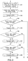
- Figure 3 is a flow chart illustrating determination of LPC filters to be transmitted in a configuration where four (4) LPC filters can be calculated and transmitted in a super-frame.
- quantized filter LPC1 is transmitted only when ACELP and/or TCX256 is selected for the first half of the super-frame.
- filter LPC3 is transmitted only when ACELP and/or TCX256 is used for the second half of that super-frame.
- Operation 301 Filter LPC1 of frame 1 of the super-frame, filter LPC2 of frame 2 of the super-frame, filter LPC3 of frame 3 of the super-frame, and filter LPC4 of frame 4 of the super-frame are quantized using for example the quantization stategy illustrated and described in relation to Figures 2 and 5 . Of course, other quantization strategies are possible.
- Operation 302 Closed-loop selection of the coding modes as described hereinabove is performed.
- the quantized filter LPC4 is transmitted to the decoder for example through the transmitter 105 of Figure 1 .
- the decoder comprises:
- Operation 304 If the super-frame is coded using mode TCX1024, no further transmission is required.
- Operation 305 If the first, second, third and fourth frames of the super-frame are not coded using mode TCX1024, the quantized filter LPC2 and an index indicative of one of the absolute quantization mode and the differential quantization mode are transmitted to the decoder for example through the transmitter 105 of Figure 1 .
- the decoder comprises:
- Operation 306 If frames 1 and 2 of the super-frame are coded using mode TCX512, the quantized filter LPC1 is not transmitted to the decoder.
- Operation 307 If frames 1 and 2 of the super-frame are not coded using mode TCX512, i.e. if frames 1 and 2 of the super-frame are coded using ACELP or TCX256, the quantized filter LPC1, and an index indicative of one of the absolute quantization mode, the differential quantization mode relative to quantized filter LPC2 used as reference, and the differential quantization mode relative to (quantized filter LPC2+quantized filter LPC0)/2 used as reference are transmitted to the decoder for example through the transmitter 105 of Figure 1 .
- the decoder comprises:
- Operation 308 If frames 3 and 4 of the super-frame are coded using mode TCX512, the quantized filter LPC3 is not transmitted to the decoder.
- Operation 309 If frames 3 and 4 of the super-frame are not coded using mode TCX512, i.e. if frames 3 and 4 of the super-frame are coded using ACELP or TCX256, the quantized filter LPC3 and the index indicative of one of the absolute quantization mode, the differential quantization mode relative to quantized filter LPC2 used as reference, the differential quantization mode relative to quantized filter LPC4 used as reference, and the differential quantization mode relative to (quantized filter LPC2+quantized filter LPC4)/2 used as reference are transmitted to the decoder for example through the transmitter 105 of Figure 1 .
- the decoder comprises:
- the above described "out-of-the loop" quantization scheme can be extended to coding more than four (4) LPC filters: for example to quantize and transmit filter LPC0 together with the super-frame.
- filter LPC0 corresponding to the last LCP filter (LPC4) calculated during the previous super-frame could be, as a non-limitative example, be quantized relative to filter LPC4 since this filter LPC4 is always available as a reference.
- Quantized filter LPC0 is transmitted to the decoder along with an index indicative of one of the absolute quantization mode and the differential quantization mode.
- the decoder comprises comprises:
- Transmitting filter LPC0 to the decoder is useful to initialize an LPC-based codec in the case of switching from a non-LPC-based coding mode to an LPC-based coding mode.
- non-LPC-based coding modes are: pulse code modulation (PCM), and transform coding used for example by MP3 and by the advanced audio codec AAC.
- LPC-based coding modes are: code excited linear prediction (CELP) and algebraic CELP (ACELP) used by the AMR-WB+ codec [1].
- LPC-based codecs one or several LPC filters per frame (or per super-frame) are estimated and transmitted to the decoder.
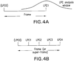
- this LPC filter is most often estimated using an LPC analysis window centered on the end of the frame as represented in Figure 4a .
- LPC filters are transmitted per frame (or per super-frame as in the AMR-WB+ codec), they are most often estimated at regularly spaced positions over the length of the frame as represented on Figure 4b .
- Filter LPC0 in Figures 4a and 4b is in fact the last LPC filter of the previous frame (or super-frame) which is quantized and transmitted to the decoder.
- Typical LPC-based codecs generally use interpolated values for the LPC filters.
- the LPC-based codec would typically divide the frame into four (4) sub-frames and use a different interpolated LPC filter for each sub-frame, the LPC filter of the first sub-frame being closer to filter LPC0 and the LPC filter of the 4 th sub-frame being closer to filter LPC1.
- the filter LPC0 used to operate the LPC-based codec is normally not available at the first frame following the switch from the non-LPC-based coding mode to the LPC-based coding mode.
- filter LPC0 which is available both at the coder and the decoder when coding and decoding the first frame after the switch from the non-LPC-based coding mode to the LPC-based coding mode. More specifically, the value of the filter LPC0 is obtained at the decoder from the parameters transmitted from the coder.
- the filter LPC0 is determined at the coder (using LPC analysis well-know to those of ordinary skill in the art), quantized and transmitted to the decoder after the switch from the non-LPC-based coding mode to the LPC-based coding mode has been decided.
- the decoder uses the transmitted quantized value and the filter LPC0.
- the out-of-the-loop quantization scheme as described above, extended to more than four (4) LPC filters can be used.
- the principle of stochastic vector quantization is to search a codebook of vectors for the nearest neighbor (generally in terms of Euclidian distance or weighted Euclidian distance) of the vector to be quantized.
- a weighting Euclidian distance is generally used, each component of the vector being weighted differently depending on its value and the value of the other components [5].
- the purpose of that weighting is to make the minimization of the Euclidian distance behave as closely as possible to a minimization of the spectral distortion.
- a uniform algebraic vector quantizer does not perform an exhaustive search of a codebook. It is therefore difficult to introduce a weighting function in the distance computation.
- the LPC filters are quantized, as a non-limitative example, in the LSF domain.
- Appropriate means for converting the LPC filter in the LSF quantization domain to form the input LSF vector are therefore provided.
- the LSF residual vector i.e. the difference between the input LSF vector and a first-stage approximation of this input LSF vector, is warped using a weighting function computed from the first-stage approximation, wherein the first-stage approximation uses a stochastic absolute quantizer of the input LSF vector, a differential quantizer of the input LSF vector, an interpolator of the input LSF vector, or other element that gives an estimate of the input LSF vector to be quantized.
- Warping means that different weights are applied to the components of the LSF residual vector. Because the first-stage approximation is also available at the decoder, the inverse weights can also be computed at the decoder and the inverse warping can be applied to the quantized LSF residual vector. Warping the LSF residual vector according to a model that minimizes the spectral distortion is useful when the quantizer is uniform.
- the quantized LSFs received at the decoder are a combination of the first-stage approximation with a variable bit rate quantization, for example AVQ (Algebraic Vector Quantization), refinement which is inverse-warped at the decoder.
- AVQ Algebraic Vector Quantization
- Operation 601 A calculator computes a first-stage approximation 608 of the input LSF vector 607.
- Operation 602 A subtractor subtracts the first-stage approximation 608 from Operation 601 from the input LSF vector 607 to produce a residual LSF vector 609.
- Operation 603 A calculator derives a LSF weighting function 610 from the first-stage approximation 608 of Operation 601.
- Operation 604 A multiplier, or warper, applies the LSF weighting function 610 from Operation 603 to the residual LSF vector 609 from Operation 602.
- a variable bit rate quantizer for example an algebraic vector quantizer (AVQ) quantizes the resulting weighted residual LSF vector 611 to supply a quantized weighted residual LSF vector 612.
- AVQ algebraic vector quantizer
- Operation 606 A multiplexer is responsive to the first-stage approximation 608 from Operation 601 and the quantized weighted residual LSF vector 612 from Operation 605 to multiplex and transmit the corresponding coded indices 613.
- the first-stage approximation can be calculated in different ways.
- the calculator of the first-stage approximation 608 can be an absolute stochastic vector quantizer of the input LSF vector 607 with a small number of bits, or a differential quantizer of the input LSF vector 607 using a reference as explained above where the first-stage approximation is the reference itself.
- the calculator of the first-stage approximation 608 can be an absolute quantizer with 8 bits, or quantized filter LPC2 or (quantized filter LPC2+quantized filter LPC0)/2.
- Operation 701 The coded indices 707 from the coder are demultiplexed by a demultiplexer.
- the demultiplexed coded indices include the first-stage approximation 708.
- Operation 703 Since the first-stage approximation is available at the decoder as at the coder (Operation 702), a calculator can be used to calculate the inverse LSF weighting function 709.
- Operation 704 Decoded indices 710 representative of the quantized weighted residual LSF vector are supplied to a variable bit rate inverse vector quantizer, for example an algebraic inverse vector quantizer (inverse AVQ) to recover the weighted residual LSF vector 711.
- a variable bit rate inverse vector quantizer for example an algebraic inverse vector quantizer (inverse AVQ) to recover the weighted residual LSF vector 711.
- Operation 705 A multiplier multiplies the weighted residual LSF vector 711 from Operation 704 by the inverse LSF weighting function 709 from Operation 703 to recover the residual LSF vector 712.
- Operation 706 An adder sums the first-stage approximation 708 from Operation 702 with the residual LSF vector 712 from Operation 705 to form the decoded LSF vector 713.
- the decoded LSF vector 713 is a combination of the first-stage approximation from Operation 702 with the variable bit rate inverse quantization refinement (Operation 704) which is inverse-weighted (Operation 705) at the decoder.
- a given LPC filter can be quantized using several quantization modes including absolute quantization and differential quantization using several references.
- the first-stage approximation depends on the quantization mode.
- the first-stage approximation can use a vector quantizer with a small number of bits (e.g. 8 bits).
- the first-stage approximation constitutes the reference itself.
- the first-stage approximation can be one of the following:
- the first-stage approximation is calculated using a p -dimensional, 8-bit stochastic vector quantizer applied to the input LSF vector.
- a codebook search uses a weighted Euclidian distance in which each component of the squared difference between the input LSF vector and the codebook entry is multiplied by the weight wt ( i ).
- the first-stage approximation is based on already quantized LPC filters.
- the set of LPC filters is quantized in the following order: LPC4, LPC2, LPC1 and then LPC3.
- the optional filter LPC0 is quantized after the filter LPC4. Therefore differential quantization of filter LPC2 can only be done with respect to LPC4, while differential quantization of filter LPC3 can be done with respect to LPC2, LPC4 or a combination of both LPC2 and LPC4; LPC1 is not considered a good choice because it is not adjacent to LPC3.
- the residual LSF vector 609 from Operation 602 is weighted (Operation 604) with the weighting function 610 from Operation 603 computed based on the first-stage approximation ⁇ 1 st ( i ) to obtain a warped residual LSF vector 611 (Operation 604).
- the warped residual LSF vector 611 is then quantized using a variable bit rate quantizer, for example an algebraic vector quantizer (Operation 605).
- variable bit rate vector quantizer chooses the bit rate for a certain vector based on its average energy.
- the four (4) LPC filters in a super-frame, as well as the optional LPC0 filter are quantized according to Figure 5 .
- Table 2 shows the used scaling factor for each quantization mode, and the encoding of the mode index used in this example.
- the quantization mode specifies which of the absolute or differential quantization is used, and in case of differential quantization it specifies the used reference filter.
- the reference filter used in differential quantization is the actual first-stage approximation for variable bit rate quantizing.
- Figure 8 is a schematic block diagram explaining the quantization procedure as described herein above.
- the input LSF vector 800 is supplied to an absolute quantizer (Operation 801) for performing, for example, a 8-bit absolute vector quantization of the input LSF vector 800.
- the input LSF vector is also supplied to differential quantizers (Operations 801 1 , 801 2 , ... , 801 n ) for performing differential quantization of the input LSF vector 800.
- the differential quantizers use respective, different references as explained in the foregoing description with reference to Figure 1 .
- the 8-bit VQ in Operation 801 and references in Operations 801 1 , 801 2 , ... , 801 n represent the first-stage approximation.
- a calculator calculates a residual LSF vector from the first stage approximation vector from the Operations 801, 801 1 , 801 2 , ... , 801 n , respectively.
- the residual vector is calculated as the difference between the input vector and the first-stage approximation. This corresponds to Operations 601 and 602 of Figure 6 .
- a calculator calculates a weighting function to warp the residual LSF vector from the Operations 802, 802 1 , 802 2 , ... , 802 n , respectively. This corresponds to Operations 601 and 603 of Figure 6 .
- a warper multiplies the residual LSF vector from the Operations 802, 802 1 , 802 2 , ... , 802 n , respectively, by the weighting function from the Operations 803, 803 1 , 803 2 , ... , 803 n , respectively.
- a variable bit rate quantizer for example an algebraic vector quantizer (AVQ) quantizes the resulting weighted residual LSF vector from the Operations 804, 804 1 , 804 2 , ... , 804 n , respectively, to supply a quantized weighted residual LSF vector.
- AVQ algebraic vector quantizer
- the selection of a quantization mode is performed by a selector amongst absolute quantization (Operation 801) and differential quantization using one of the references 1, 2, ... , n (Operations 801 1 , 801 2 , ... , 801 n ).
- Operation 806 could select the quantization mode (Operations 801, 801 1 , 801 2 , ... , 801 n ) that yields a lower distortion for a given bit rate or the lower bit rate for a target level of distortion.
- the selection can be performed in closed-loop or in open-loop.
- the Operation 806 predetermines the reference based on the value of the Linear Prediction Coefficients of the LPC filter to be quantized and of the Linear Prediction Coefficients of the available reference LPC filters.
- Operation 807 Following the selection in Operation 806, a transmitter (Operation 807) communicates or signals to the decoder (not shown) an index indicative of:
- Some specific bits are transmitted to the decoder for such signaling.
- a possible algebraic vector quantizer (AVQ) used for example in Operation 605 of Figure 6 and Operations 805, 805 1 , 805 2 , ... , 805 n of Figure 8 is based on the 8-dimensional RE8 lattice vector quantizer used to quantize the spectrum in TCX modes of AMR-WB+ [1].
- each weighted residual LSF vector is split into two 8-dimensional sub-vectors B 1 and B 2 .
- Each of these two sub-vectors is quantized using the three-operation approach described below.
- LSF vectors do not have all the same sensitivity to quantization error, whereby a certain quantization error applied to one LSF vector can have more impact on spectral distortion than the same quantization error applied to another LSF vector.
- the weighting operation gives the same relative sensitivity to all weighted LSF vectors.
- the AVQ has the particularity of introducing the same level of quantization error to the weighted LSF vectors (uniform quantization error).
- the inverse weighting which is applied to inverse-quantized weighted LSF vectors is also obviously applied to the quantization error.
- the originally uniform quantization error is distributed among quantized LSF vectors, the more sensitive LSF vectors acquiring a smaller quantization error and the less sensitive LSF vectors acquiring a larger quantization error.
- the impact of quantization error on spectral distortion is minimized.
- the RE8 quantizer uses a fixed and predetermined quantization. As a consequence, the bit rate required to encode a subvector increases with the amplitude of this subvector.
- the scaling factor W controls the amplitude of the weighted LSF vectors. Therefore, the scaling factor W also controls both the bit rate needed to quantize the LSF vector and the average spectral distortion.
- an 8-dimensional sub-vector B k is rounded as a point in the lattice RE 8 , to produce its quantized version, B ⁇ k .
- searching for the nearest neighbour in the lattice RE 8 is equivalent to searching for the nearest neighbour in the lattice 2 D 8 , then searching for the nearest neighbour in the lattice 2 D 8 + (1,1,1,1,1,1,1), and finally selecting the best of those two lattice points.
- lattice RE 8 From this definition of lattice RE 8 , it is straightforward to develop a fast algorithm to search for the nearest neighbour of an 8-dimensional sub-vector B k among all lattice points in lattice RE 8 . This can be done by applying the following operations.
- the components of sub-vector B k are floating point values, and the result of the quantization, B ⁇ k , will be a vector of integers.
- each 8-dimensional sub-vector B k was rounded as a point in the lattice RE 8 .
- an index is computed for each c k for transmission to the decoder. The computation of this index is performed as follows.
- the base codebook C in the LPC quantizer can be either codebook Q 0 , Q 2 , Q 3 or Q 4 from Reference [6].
- the Voronoi extension is applied, using this time only the codebook Q 3 or Q 4 . Note that here, Q 2 ⁇ Q 3 but Q 3 ⁇ Q 4 .
- the codebook numbers n k are encoded using a variable-length code which depends on the position of the LPC filter and on the quantization mode, as indicated in Table 3.
- the codebook number n k is encoded as a variable length code, as follows:
- the codebook number n k is encoded as a unary code, as follows:
- the codebook number n k is encoded as a variable length code, as follows:
- the actual number of quantized LPC filters transmitted from the coder to the decoder is not fixed but rather depends on the ACELP/TCX decision taken at the coder.
- long TCX (TCX1024) requires only the transmission of quantized filter LPC4 while any combination involving ACELP or short TCX (TCX256) requires the transmission of all four (4) quantized LPC filters LPC1 to LPC4. Only the quantized LPC filters that are required by the ACELP/TCX mode configuration are actually transmitted.
- the actual number of quantized LPC filters coded within the bitstream depends on the ACELP/TCX mode combination of the super-frame.
- the mode value is 0 for ACELP, 1 for TCX256, 2 for TCX512, 3 for TCX1024.
- optional quantized filter LPC0 is transmitted for the first super-frame of each segment coded using the linear-prediction based codec.
- the order in which the quantized LPC filters are normally found in the bitstream is: LPC4, the optional LPC0, LPC2, LPC1, and LPC3.
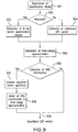
- Figure 9 is a schematic block diagram summarizing the decoding process.
- the decoder comprises means for receiving and extracting, for example a demultiplexer, from the received bit stream the quantization indices corresponding to each of the quantized LPC filters required by the ACELP/TCX mode combination.
- a determiner of quantization mode extracts from the bit stream received from the coder the index or information related to the quantization mode, and determines whether the quantization mode is the absolute or differential quantization mode as indicated in Table 2.
- Operations 903 and 905 When Operations 901 and 902 determine that the quantization mode is the absolute quantization mode, an extractor extracts from the bit stream the index or indices corresponding to the stochastic VQ-quantized first-stage approximation (Operation 903). A calculator then computes the first-stage approximation through inverse-quantization (Operation 905).
- Operations 904 and 905 When Operations 901 and 902 determine that the quantization mode is the differential quantization mode (not the absolute quantization mode), an extractor extracts from the bit stream the indices or information representative of the reference amongst the plurality of possible references, for example the reference LPC vector (Operation 904). The calculator then computes from this information the first-stage approximation as described with reference to Table 2 (Operation 905).
- an extractor of VQ information extracts from the bit stream received from the coder variable bit rate VQ information, for example AVQ information. More specifically, as a non-limitative example, the AVQ information for the two residual LSF sub-vectors B ⁇ k are extracted from the bit stream.
- the AVQ information normally comprises two encoded codebook numbers and the corresponding AVQ indices. The only exception is when filter LPC1 is differentially quantized relative to (quantized filter LPC0+quantized filter LPC2)/2, since in this case there is no AVQ information present in the bit stream. In the case of the latter exception, the quantized LSF vector 909 is outputted as the first-stage approximation from Operation 905.
- Operation 907 An inverse algebraic vector quantizer receives the extracted AVQ information from Operation 906 to inverse quantize, or inverse weight and recover the AVQ contribution.
- Decoding the LPC filters involves decoding the extracted AVQ information, for example the AVQ parameters describing each quantized sub-vector B ⁇ k of the weighted residual LSF vector.
- each sub-vector B k has a dimension 8.
- the AVQ parameters for each sub-vector B k are described in the second operation of the above described algebraic vector quantization. For each quantized sub-vector B ⁇ k , three sets of binary indices are sent by the coder to the decoder:
- the base codebook is either codebook Q 0 , Q 2 , Q 3 or Q 4 from Reference [6]. No bits are then required to transmit vector k . Otherwise, when Voronoi extension is used because B ⁇ k is large enough, then only Q 3 or Q 4 from Reference [6] is used as a base codebook. The selection of Q 3 or Q 4 is implicit in the codebook number value n k , as described in the second operation of the above described algebraic vector quantization.
- Operation 908 An adder sums the first-stage approximation from Operation 905 to the inverse-weighed AVQ contribution from Operation 907 to reconstruct and recover the quantized LSF vector 909.
Applications Claiming Priority (3)
| Application Number | Priority Date | Filing Date | Title |
|---|---|---|---|
| US12966908P | 2008-07-10 | 2008-07-10 | |
| US20207509P | 2009-01-27 | 2009-01-27 | |
| PCT/CA2009/000981 WO2010003254A1 (en) | 2008-07-10 | 2009-07-10 | Multi-reference lpc filter quantization and inverse quantization device and method |
Publications (3)
| Publication Number | Publication Date |
|---|---|
| EP2301022A1 EP2301022A1 (en) | 2011-03-30 |
| EP2301022A4 EP2301022A4 (en) | 2012-08-15 |
| EP2301022B1 true EP2301022B1 (en) | 2017-09-06 |
Family
ID=41506638
Family Applications (3)
| Application Number | Title | Priority Date | Filing Date |
|---|---|---|---|
| EP09793770.0A Active EP2301022B1 (en) | 2008-07-10 | 2009-07-10 | Multi-reference lpc filter quantization device and method |
| EP09793768.4A Active EP2301021B1 (en) | 2008-07-10 | 2009-07-10 | Device and method for quantizing lpc filters in a super-frame |
| EP09793769.2A Active EP2313887B1 (en) | 2008-07-10 | 2009-07-10 | Variable bit rate lpc filter quantizing and inverse quantizing device and method |
Family Applications After (2)
| Application Number | Title | Priority Date | Filing Date |
|---|---|---|---|
| EP09793768.4A Active EP2301021B1 (en) | 2008-07-10 | 2009-07-10 | Device and method for quantizing lpc filters in a super-frame |
| EP09793769.2A Active EP2313887B1 (en) | 2008-07-10 | 2009-07-10 | Variable bit rate lpc filter quantizing and inverse quantizing device and method |
Country Status (17)
| Country | Link |
|---|---|
| US (4) | US8332213B2 (da) |
| EP (3) | EP2301022B1 (da) |
| JP (2) | JP2011527442A (da) |
| KR (2) | KR101604774B1 (da) |
| CN (2) | CN102119414B (da) |
| BR (1) | BRPI0915450B1 (da) |
| CA (5) | CA2729752C (da) |
| CY (3) | CY1119501T1 (da) |
| DK (3) | DK2313887T3 (da) |
| ES (3) | ES2650492T3 (da) |
| HK (2) | HK1153840A1 (da) |
| MX (1) | MX2011000363A (da) |
| NO (1) | NO2313887T3 (da) |
| PL (1) | PL2313887T3 (da) |
| PT (3) | PT2313887T (da) |
| RU (2) | RU2011104813A (da) |
| WO (3) | WO2010003252A1 (da) |
Families Citing this family (23)
| Publication number | Priority date | Publication date | Assignee | Title |
|---|---|---|---|---|
| WO2008107027A1 (en) | 2007-03-02 | 2008-09-12 | Telefonaktiebolaget Lm Ericsson (Publ) | Methods and arrangements in a telecommunications network |
| CN101308655B (zh) * | 2007-05-16 | 2011-07-06 | 展讯通信(上海)有限公司 | 一种音频编解码方法与装置 |
| DE602008005250D1 (de) * | 2008-01-04 | 2011-04-14 | Dolby Sweden Ab | Audiokodierer und -dekodierer |
| US20110158189A1 (en) * | 2009-12-29 | 2011-06-30 | Industrial Technology Research Institute | Methods and Apparatus for Multi-Transmitter Collaborative Communications Systems |
| KR101660843B1 (ko) | 2010-05-27 | 2016-09-29 | 삼성전자주식회사 | Lpc 계수 양자화를 위한 가중치 함수 결정 장치 및 방법 |
| CN102934161B (zh) * | 2010-06-14 | 2015-08-26 | 松下电器产业株式会社 | 音频混合编码装置以及音频混合解码装置 |
| CA3025108C (en) | 2010-07-02 | 2020-10-27 | Dolby International Ab | Audio decoding with selective post filtering |
| KR101747917B1 (ko) * | 2010-10-18 | 2017-06-15 | 삼성전자주식회사 | 선형 예측 계수를 양자화하기 위한 저복잡도를 가지는 가중치 함수 결정 장치 및 방법 |
| EP2761616A4 (en) * | 2011-10-18 | 2015-06-24 | Ericsson Telefon Ab L M | IMPROVED METHOD AND DEVICE FOR AN ADAPTIVE MULTIRATE CODEC |
| US9842598B2 (en) * | 2013-02-21 | 2017-12-12 | Qualcomm Incorporated | Systems and methods for mitigating potential frame instability |
| US9208775B2 (en) * | 2013-02-21 | 2015-12-08 | Qualcomm Incorporated | Systems and methods for determining pitch pulse period signal boundaries |
| RU2640722C2 (ru) | 2013-04-05 | 2018-01-11 | Долби Интернешнл Аб | Усовершенствованный квантователь |
| RU2643489C2 (ru) | 2013-05-24 | 2018-02-01 | Долби Интернэшнл Аб | Аудиокодер и аудиодекодер |
| FR3008533A1 (fr) * | 2013-07-12 | 2015-01-16 | Orange | Facteur d'echelle optimise pour l'extension de bande de frequence dans un decodeur de signaux audiofrequences |
| CN104299614B (zh) * | 2013-07-16 | 2017-12-29 | 华为技术有限公司 | 解码方法和解码装置 |
| US10970967B2 (en) * | 2014-09-24 | 2021-04-06 | Jcm American Corporation | Electronic voucher ticket system |
| US9407989B1 (en) | 2015-06-30 | 2016-08-02 | Arthur Woodrow | Closed audio circuit |
| EP3335215B1 (en) * | 2016-03-21 | 2020-05-13 | Huawei Technologies Co., Ltd. | Adaptive quantization of weighted matrix coefficients |
| US10366698B2 (en) | 2016-08-30 | 2019-07-30 | Dts, Inc. | Variable length coding of indices and bit scheduling in a pyramid vector quantizer |
| US11532316B2 (en) | 2017-12-19 | 2022-12-20 | Dolby International Ab | Methods and apparatus systems for unified speech and audio decoding improvements |
| JP7326285B2 (ja) | 2017-12-19 | 2023-08-15 | ドルビー・インターナショナル・アーベー | 音声音響統合復号および符号化のqmfに基づく高調波トランスポーザーの改良のための方法、機器、およびシステム |
| TWI812658B (zh) | 2017-12-19 | 2023-08-21 | 瑞典商都比國際公司 | 用於統一語音及音訊之解碼及編碼去關聯濾波器之改良之方法、裝置及系統 |
| US10950251B2 (en) * | 2018-03-05 | 2021-03-16 | Dts, Inc. | Coding of harmonic signals in transform-based audio codecs |
Family Cites Families (79)
| Publication number | Priority date | Publication date | Assignee | Title |
|---|---|---|---|---|
| DE69133296T2 (de) | 1990-02-22 | 2004-01-29 | Nec Corp | Sprachcodierer |
| US6006174A (en) * | 1990-10-03 | 1999-12-21 | Interdigital Technology Coporation | Multiple impulse excitation speech encoder and decoder |
| US5255339A (en) * | 1991-07-19 | 1993-10-19 | Motorola, Inc. | Low bit rate vocoder means and method |
| US5233660A (en) | 1991-09-10 | 1993-08-03 | At&T Bell Laboratories | Method and apparatus for low-delay celp speech coding and decoding |
| FI90477C (fi) | 1992-03-23 | 1994-02-10 | Nokia Mobile Phones Ltd | Puhesignaalin laadun parannusmenetelmä lineaarista ennustusta käyttävään koodausjärjestelmään |
| EP0577488B9 (en) * | 1992-06-29 | 2007-10-03 | Nippon Telegraph And Telephone Corporation | Speech coding method and apparatus for the same |
| JP3255189B2 (ja) | 1992-12-01 | 2002-02-12 | 日本電信電話株式会社 | 音声パラメータの符号化方法および復号方法 |
| AU668817B2 (en) * | 1993-03-26 | 1996-05-16 | Blackberry Limited | Vector quantizer method and apparatus |
| AU7960994A (en) * | 1993-10-08 | 1995-05-04 | Comsat Corporation | Improved low bit rate vocoders and methods of operation therefor |
| FI98163C (fi) * | 1994-02-08 | 1997-04-25 | Nokia Mobile Phones Ltd | Koodausjärjestelmä parametriseen puheenkoodaukseen |
| JP3013698B2 (ja) * | 1994-04-20 | 2000-02-28 | 松下電器産業株式会社 | ベクトル量子化符号化装置と復号化装置 |
| CA2154911C (en) * | 1994-08-02 | 2001-01-02 | Kazunori Ozawa | Speech coding device |
| JP3235703B2 (ja) * | 1995-03-10 | 2001-12-04 | 日本電信電話株式会社 | ディジタルフィルタのフィルタ係数決定方法 |
| US6263307B1 (en) | 1995-04-19 | 2001-07-17 | Texas Instruments Incorporated | Adaptive weiner filtering using line spectral frequencies |
| US5649051A (en) | 1995-06-01 | 1997-07-15 | Rothweiler; Joseph Harvey | Constant data rate speech encoder for limited bandwidth path |
| JP3537008B2 (ja) | 1995-07-17 | 2004-06-14 | 株式会社日立国際電気 | 音声符号化通信方式とその送受信装置 |
| TW321810B (da) | 1995-10-26 | 1997-12-01 | Sony Co Ltd | |
| US5956674A (en) | 1995-12-01 | 1999-09-21 | Digital Theater Systems, Inc. | Multi-channel predictive subband audio coder using psychoacoustic adaptive bit allocation in frequency, time and over the multiple channels |
| JP3094908B2 (ja) | 1996-04-17 | 2000-10-03 | 日本電気株式会社 | 音声符号化装置 |
| US6904404B1 (en) * | 1996-07-01 | 2005-06-07 | Matsushita Electric Industrial Co., Ltd. | Multistage inverse quantization having the plurality of frequency bands |
| JP3357795B2 (ja) | 1996-08-16 | 2002-12-16 | 株式会社東芝 | 音声符号化方法および装置 |
| JP3707153B2 (ja) * | 1996-09-24 | 2005-10-19 | ソニー株式会社 | ベクトル量子化方法、音声符号化方法及び装置 |
| JP3707154B2 (ja) | 1996-09-24 | 2005-10-19 | ソニー株式会社 | 音声符号化方法及び装置 |
| US6154499A (en) * | 1996-10-21 | 2000-11-28 | Comsat Corporation | Communication systems using nested coder and compatible channel coding |
| US6167375A (en) | 1997-03-17 | 2000-12-26 | Kabushiki Kaisha Toshiba | Method for encoding and decoding a speech signal including background noise |
| DE19730130C2 (de) | 1997-07-14 | 2002-02-28 | Fraunhofer Ges Forschung | Verfahren zum Codieren eines Audiosignals |
| TW408298B (en) | 1997-08-28 | 2000-10-11 | Texas Instruments Inc | Improved method for switched-predictive quantization |
| US6889185B1 (en) * | 1997-08-28 | 2005-05-03 | Texas Instruments Incorporated | Quantization of linear prediction coefficients using perceptual weighting |
| US6233550B1 (en) | 1997-08-29 | 2001-05-15 | The Regents Of The University Of California | Method and apparatus for hybrid coding of speech at 4kbps |
| US6311153B1 (en) * | 1997-10-03 | 2001-10-30 | Matsushita Electric Industrial Co., Ltd. | Speech recognition method and apparatus using frequency warping of linear prediction coefficients |
| JP3842432B2 (ja) | 1998-04-20 | 2006-11-08 | 株式会社東芝 | ベクトル量子化方法 |
| US6823303B1 (en) * | 1998-08-24 | 2004-11-23 | Conexant Systems, Inc. | Speech encoder using voice activity detection in coding noise |
| US7072832B1 (en) * | 1998-08-24 | 2006-07-04 | Mindspeed Technologies, Inc. | System for speech encoding having an adaptive encoding arrangement |
| US6507814B1 (en) | 1998-08-24 | 2003-01-14 | Conexant Systems, Inc. | Pitch determination using speech classification and prior pitch estimation |
| US7272556B1 (en) | 1998-09-23 | 2007-09-18 | Lucent Technologies Inc. | Scalable and embedded codec for speech and audio signals |
| FR2784218B1 (fr) | 1998-10-06 | 2000-12-08 | Thomson Csf | Procede de codage de la parole a bas debit |
| JP3343082B2 (ja) * | 1998-10-27 | 2002-11-11 | 松下電器産業株式会社 | Celp型音声符号化装置 |
| US6691082B1 (en) | 1999-08-03 | 2004-02-10 | Lucent Technologies Inc | Method and system for sub-band hybrid coding |
| AU7486200A (en) | 1999-09-22 | 2001-04-24 | Conexant Systems, Inc. | Multimode speech encoder |
| US6782360B1 (en) | 1999-09-22 | 2004-08-24 | Mindspeed Technologies, Inc. | Gain quantization for a CELP speech coder |
| US7315815B1 (en) * | 1999-09-22 | 2008-01-01 | Microsoft Corporation | LPC-harmonic vocoder with superframe structure |
| US6792405B2 (en) * | 1999-12-10 | 2004-09-14 | At&T Corp. | Bitstream-based feature extraction method for a front-end speech recognizer |
| JP2002055699A (ja) * | 2000-08-10 | 2002-02-20 | Mitsubishi Electric Corp | 音声符号化装置および音声符号化方法 |
| JP2002055700A (ja) | 2000-08-11 | 2002-02-20 | Hitachi Kokusai Electric Inc | 音声信号符号復号化システム |
| CZ304196B6 (cs) * | 2000-11-30 | 2013-12-27 | Panasonic Corporation | Vektorové kvantizační zařízení LPC parametru, kodér řeči a přijímací zařízení signálu řeči |
| US6996523B1 (en) | 2001-02-13 | 2006-02-07 | Hughes Electronics Corporation | Prototype waveform magnitude quantization for a frequency domain interpolative speech codec system |
| KR20020075592A (ko) | 2001-03-26 | 2002-10-05 | 한국전자통신연구원 | 광대역 음성 부호화기용 lsf 양자화기 |
| US7003454B2 (en) * | 2001-05-16 | 2006-02-21 | Nokia Corporation | Method and system for line spectral frequency vector quantization in speech codec |
| US6584437B2 (en) * | 2001-06-11 | 2003-06-24 | Nokia Mobile Phones Ltd. | Method and apparatus for coding successive pitch periods in speech signal |
| US6658383B2 (en) | 2001-06-26 | 2003-12-02 | Microsoft Corporation | Method for coding speech and music signals |
| US6711027B2 (en) | 2001-07-23 | 2004-03-23 | Intel Corporation | Modules having paths of different impedances |
| US7647223B2 (en) | 2001-08-16 | 2010-01-12 | Broadcom Corporation | Robust composite quantization with sub-quantizers and inverse sub-quantizers using illegal space |
| US7386447B2 (en) * | 2001-11-02 | 2008-06-10 | Texas Instruments Incorporated | Speech coder and method |
| SE521600C2 (sv) | 2001-12-04 | 2003-11-18 | Global Ip Sound Ab | Lågbittaktskodek |
| JP4263412B2 (ja) * | 2002-01-29 | 2009-05-13 | 富士通株式会社 | 音声符号変換方法 |
| US20040002856A1 (en) | 2002-03-08 | 2004-01-01 | Udaya Bhaskar | Multi-rate frequency domain interpolative speech CODEC system |
| AU2003247040A1 (en) | 2002-07-16 | 2004-02-02 | Koninklijke Philips Electronics N.V. | Audio coding |
| US7536305B2 (en) | 2002-09-04 | 2009-05-19 | Microsoft Corporation | Mixed lossless audio compression |
| CA2511516C (en) | 2002-12-24 | 2009-03-03 | Nokia Corporation | Method and device for robust predictive vector quantization of linear prediction parameters in variable bit rate speech coding |
| KR100486732B1 (ko) * | 2003-02-19 | 2005-05-03 | 삼성전자주식회사 | 블럭제한된 트렐리스 부호화 양자화방법과 음성부호화시스템에있어서 이를 채용한 라인스펙트럼주파수 계수양자화방법 및 장치 |
| WO2004090864A2 (en) | 2003-03-12 | 2004-10-21 | The Indian Institute Of Technology, Bombay | Method and apparatus for the encoding and decoding of speech |
| ATE368279T1 (de) * | 2003-05-01 | 2007-08-15 | Nokia Corp | Verfahren und vorrichtung zur quantisierung des verstärkungsfaktors in einem breitbandsprachkodierer mit variabler bitrate |
| FR2867649A1 (fr) | 2003-12-10 | 2005-09-16 | France Telecom | Procede de codage multiple optimise |
| CA2457988A1 (en) * | 2004-02-18 | 2005-08-18 | Voiceage Corporation | Methods and devices for audio compression based on acelp/tcx coding and multi-rate lattice vector quantization |
| FR2869151B1 (fr) | 2004-04-19 | 2007-01-26 | Thales Sa | Procede de quantification d'un codeur de parole a tres bas debit |
| BRPI0510303A (pt) * | 2004-04-27 | 2007-10-02 | Matsushita Electric Ind Co Ltd | dispositivo de codificação escalável, dispositivo de decodificação escalável, e seu método |
| US7739120B2 (en) | 2004-05-17 | 2010-06-15 | Nokia Corporation | Selection of coding models for encoding an audio signal |
| US7596486B2 (en) | 2004-05-19 | 2009-09-29 | Nokia Corporation | Encoding an audio signal using different audio coder modes |
| JP4871501B2 (ja) | 2004-11-04 | 2012-02-08 | パナソニック株式会社 | ベクトル変換装置及びベクトル変換方法 |
| MX2007012184A (es) | 2005-04-01 | 2007-12-11 | Qualcomm Inc | Sistemas, metodos y aparatos para codificacion de dialogo de banda ancha. |
| KR20070038439A (ko) | 2005-10-05 | 2007-04-10 | 엘지전자 주식회사 | 신호 처리 방법 및 장치 |
| JP2007142547A (ja) | 2005-11-15 | 2007-06-07 | Oki Electric Ind Co Ltd | 符号化方法及び復号化方法とその符号器及び復号器 |
| JP5241701B2 (ja) * | 2007-03-02 | 2013-07-17 | パナソニック株式会社 | 符号化装置および符号化方法 |
| CN101110214B (zh) * | 2007-08-10 | 2011-08-17 | 北京理工大学 | 一种基于多描述格型矢量量化技术的语音编码方法 |
| US8515767B2 (en) * | 2007-11-04 | 2013-08-20 | Qualcomm Incorporated | Technique for encoding/decoding of codebook indices for quantized MDCT spectrum in scalable speech and audio codecs |
| DE602008005250D1 (de) * | 2008-01-04 | 2011-04-14 | Dolby Sweden Ab | Audiokodierer und -dekodierer |
| EP2234104B1 (en) * | 2008-01-16 | 2017-06-14 | III Holdings 12, LLC | Vector quantizer, vector inverse quantizer, and methods therefor |
| US8386271B2 (en) | 2008-03-25 | 2013-02-26 | Microsoft Corporation | Lossless and near lossless scalable audio codec |
| GB2466670B (en) * | 2009-01-06 | 2012-11-14 | Skype | Speech encoding |
-
2009
- 2009-07-10 CA CA2729752A patent/CA2729752C/en active Active
- 2009-07-10 CN CN2009801267394A patent/CN102119414B/zh active Active
- 2009-07-10 JP JP2011516938A patent/JP2011527442A/ja active Pending
- 2009-07-10 CA CA2729665A patent/CA2729665C/en active Active
- 2009-07-10 EP EP09793770.0A patent/EP2301022B1/en active Active
- 2009-07-10 KR KR1020117002977A patent/KR101604774B1/ko active IP Right Grant
- 2009-07-10 BR BRPI0915450-7A patent/BRPI0915450B1/pt active IP Right Grant
- 2009-07-10 WO PCT/CA2009/000979 patent/WO2010003252A1/en active Application Filing
- 2009-07-10 EP EP09793768.4A patent/EP2301021B1/en active Active
- 2009-07-10 DK DK09793769.2T patent/DK2313887T3/da active
- 2009-07-10 CA CA2729751A patent/CA2729751C/en active Active
- 2009-07-10 WO PCT/CA2009/000980 patent/WO2010003253A1/en active Application Filing
- 2009-07-10 RU RU2011104813/08A patent/RU2011104813A/ru unknown
- 2009-07-10 US US12/501,188 patent/US8332213B2/en active Active
- 2009-07-10 ES ES09793770.0T patent/ES2650492T3/es active Active
- 2009-07-10 US US12/501,197 patent/US8712764B2/en active Active
- 2009-07-10 PT PT97937692T patent/PT2313887T/pt unknown
- 2009-07-10 RU RU2011104784/08A patent/RU2509379C2/ru active
- 2009-07-10 EP EP09793769.2A patent/EP2313887B1/en active Active
- 2009-07-10 DK DK09793768.4T patent/DK2301021T3/da active
- 2009-07-10 JP JP2011516937A patent/JP5710476B2/ja active Active
- 2009-07-10 CA CA2972812A patent/CA2972812C/en active Active
- 2009-07-10 ES ES09793768.4T patent/ES2639747T3/es active Active
- 2009-07-10 CA CA2972808A patent/CA2972808C/en active Active
- 2009-07-10 PL PL09793769T patent/PL2313887T3/pl unknown
- 2009-07-10 US US12/501,201 patent/US9245532B2/en not_active Ceased
- 2009-07-10 CN CN2009801267267A patent/CN102089810B/zh active Active
- 2009-07-10 PT PT97937684T patent/PT2301021T/pt unknown
- 2009-07-10 ES ES09793769.2T patent/ES2645375T3/es active Active
- 2009-07-10 DK DK09793770.0T patent/DK2301022T3/da active
- 2009-07-10 MX MX2011000363A patent/MX2011000363A/es active IP Right Grant
- 2009-07-10 KR KR1020117002983A patent/KR101592968B1/ko active IP Right Grant
- 2009-07-10 NO NO09793769A patent/NO2313887T3/no unknown
- 2009-07-10 WO PCT/CA2009/000981 patent/WO2010003254A1/en active Application Filing
- 2009-07-10 PT PT97937700T patent/PT2301022T/pt unknown
-
2011
- 2011-07-27 HK HK11107811.9A patent/HK1153840A1/xx unknown
- 2011-08-04 HK HK11108095.4A patent/HK1154109A1/xx unknown
-
2017
- 2017-09-08 CY CY20171100951T patent/CY1119501T1/el unknown
- 2017-10-26 CY CY20171101113T patent/CY1119494T1/el unknown
- 2017-12-05 CY CY20171101272T patent/CY1119659T1/el unknown
-
2018
- 2018-01-23 US US15/877,829 patent/USRE49363E1/en active Active
Non-Patent Citations (1)
| Title |
|---|
| PHILIPPE GOURNAY ET AL: "Proposed Core Experiment on LPC Quantization for USAC", 87. MPEG MEETING; 2-2-2009 - 6-2-2009; LAUSANNE; (MOTION PICTURE EXPERT GROUP OR ISO/IEC JTC1/SC29/WG11),, no. M16147, 28 January 2009 (2009-01-28), XP030044744 * |
Also Published As
Similar Documents
| Publication | Publication Date | Title |
|---|---|---|
| USRE49363E1 (en) | Variable bit rate LPC filter quantizing and inverse quantizing device and method | |
| US7149683B2 (en) | Method and device for robust predictive vector quantization of linear prediction parameters in variable bit rate speech coding | |
| US6470313B1 (en) | Speech coding | |
| KR100718487B1 (ko) | 디지털 음성 코더들에서의 고조파 잡음 가중 | |
| kS kkSkkS et al. | km mmm SmmSZkukkS kkkk kkkLLk k kkkkkkS |
Legal Events
| Date | Code | Title | Description |
|---|---|---|---|
| PUAI | Public reference made under article 153(3) epc to a published international application that has entered the european phase |
Free format text: ORIGINAL CODE: 0009012 |
|
| 17P | Request for examination filed |
Effective date: 20110110 |
|
| AK | Designated contracting states |
Kind code of ref document: A1 Designated state(s): AT BE BG CH CY CZ DE DK EE ES FI FR GB GR HR HU IE IS IT LI LT LU LV MC MK MT NL NO PL PT RO SE SI SK SM TR |
|
| AX | Request for extension of the european patent |
Extension state: AL BA RS |
|
| DAX | Request for extension of the european patent (deleted) | ||
| A4 | Supplementary search report drawn up and despatched |
Effective date: 20120712 |
|
| RIC1 | Information provided on ipc code assigned before grant |
Ipc: G10L 19/06 20060101AFI20120706BHEP Ipc: H03M 7/30 20060101ALI20120706BHEP |
|
| 17Q | First examination report despatched |
Effective date: 20140731 |
|
| GRAP | Despatch of communication of intention to grant a patent |
Free format text: ORIGINAL CODE: EPIDOSNIGR1 |
|
| RIC1 | Information provided on ipc code assigned before grant |
Ipc: G10L 19/06 20130101AFI20161129BHEP Ipc: H03M 7/30 20060101ALI20161129BHEP Ipc: G10L 19/18 20130101ALN20161129BHEP |
|
| INTG | Intention to grant announced |
Effective date: 20170105 |
|
| RIC1 | Information provided on ipc code assigned before grant |
Ipc: H03M 7/30 20060101ALI20161220BHEP Ipc: G10L 19/06 20130101AFI20161220BHEP Ipc: G10L 19/18 20130101ALN20161220BHEP |
|
| GRAS | Grant fee paid |
Free format text: ORIGINAL CODE: EPIDOSNIGR3 |
|
| GRAJ | Information related to disapproval of communication of intention to grant by the applicant or resumption of examination proceedings by the epo deleted |
Free format text: ORIGINAL CODE: EPIDOSDIGR1 |
|
| GRAL | Information related to payment of fee for publishing/printing deleted |
Free format text: ORIGINAL CODE: EPIDOSDIGR3 |
|
| REG | Reference to a national code |
Ref country code: DE Ref legal event code: R079 Ref document number: 602009048216 Country of ref document: DE Free format text: PREVIOUS MAIN CLASS: G10L0019120000 Ipc: G10L0019060000 |
|
| INTC | Intention to grant announced (deleted) | ||
| GRAP | Despatch of communication of intention to grant a patent |
Free format text: ORIGINAL CODE: EPIDOSNIGR1 |
|
| RIC1 | Information provided on ipc code assigned before grant |
Ipc: G10L 19/06 20130101AFI20170621BHEP Ipc: H03M 7/30 20060101ALI20170621BHEP Ipc: G10L 19/18 20130101ALN20170621BHEP |
|
| GRAA | (expected) grant |
Free format text: ORIGINAL CODE: 0009210 |
|
| INTG | Intention to grant announced |
Effective date: 20170712 |
|
| AK | Designated contracting states |
Kind code of ref document: B1 Designated state(s): AT BE BG CH CY CZ DE DK EE ES FI FR GB GR HR HU IE IS IT LI LT LU LV MC MK MT NL NO PL PT RO SE SI SK SM TR |
|
| REG | Reference to a national code |
Ref country code: GB Ref legal event code: FG4D |
|
| REG | Reference to a national code |
Ref country code: AT Ref legal event code: REF Ref document number: 926659 Country of ref document: AT Kind code of ref document: T Effective date: 20170915 Ref country code: CH Ref legal event code: EP |
|
| REG | Reference to a national code |
Ref country code: IE Ref legal event code: FG4D |
|
| REG | Reference to a national code |
Ref country code: DE Ref legal event code: R096 Ref document number: 602009048216 Country of ref document: DE |
|
| REG | Reference to a national code |
Ref country code: DK Ref legal event code: T3 Effective date: 20171127 |
|
| REG | Reference to a national code |
Ref country code: SE Ref legal event code: TRGR Ref country code: PT Ref legal event code: SC4A Ref document number: 2301022 Country of ref document: PT Date of ref document: 20171212 Kind code of ref document: T Free format text: AVAILABILITY OF NATIONAL TRANSLATION Effective date: 20171204 |
|
| REG | Reference to a national code |
Ref country code: NL Ref legal event code: FP |
|
| REG | Reference to a national code |
Ref country code: ES Ref legal event code: FG2A Ref document number: 2650492 Country of ref document: ES Kind code of ref document: T3 Effective date: 20180118 |
|
| REG | Reference to a national code |
Ref country code: LT Ref legal event code: MG4D |
|
| PG25 | Lapsed in a contracting state [announced via postgrant information from national office to epo] |
Ref country code: LT Free format text: LAPSE BECAUSE OF FAILURE TO SUBMIT A TRANSLATION OF THE DESCRIPTION OR TO PAY THE FEE WITHIN THE PRESCRIBED TIME-LIMIT Effective date: 20170906 Ref country code: HR Free format text: LAPSE BECAUSE OF FAILURE TO SUBMIT A TRANSLATION OF THE DESCRIPTION OR TO PAY THE FEE WITHIN THE PRESCRIBED TIME-LIMIT Effective date: 20170906 Ref country code: NO Free format text: LAPSE BECAUSE OF FAILURE TO SUBMIT A TRANSLATION OF THE DESCRIPTION OR TO PAY THE FEE WITHIN THE PRESCRIBED TIME-LIMIT Effective date: 20171206 |
|
| PG25 | Lapsed in a contracting state [announced via postgrant information from national office to epo] |
Ref country code: BG Free format text: LAPSE BECAUSE OF FAILURE TO SUBMIT A TRANSLATION OF THE DESCRIPTION OR TO PAY THE FEE WITHIN THE PRESCRIBED TIME-LIMIT Effective date: 20171206 Ref country code: LV Free format text: LAPSE BECAUSE OF FAILURE TO SUBMIT A TRANSLATION OF THE DESCRIPTION OR TO PAY THE FEE WITHIN THE PRESCRIBED TIME-LIMIT Effective date: 20170906 |
|
| PG25 | Lapsed in a contracting state [announced via postgrant information from national office to epo] |
Ref country code: CZ Free format text: LAPSE BECAUSE OF FAILURE TO SUBMIT A TRANSLATION OF THE DESCRIPTION OR TO PAY THE FEE WITHIN THE PRESCRIBED TIME-LIMIT Effective date: 20170906 Ref country code: PL Free format text: LAPSE BECAUSE OF FAILURE TO SUBMIT A TRANSLATION OF THE DESCRIPTION OR TO PAY THE FEE WITHIN THE PRESCRIBED TIME-LIMIT Effective date: 20170906 Ref country code: RO Free format text: LAPSE BECAUSE OF FAILURE TO SUBMIT A TRANSLATION OF THE DESCRIPTION OR TO PAY THE FEE WITHIN THE PRESCRIBED TIME-LIMIT Effective date: 20170906 |
|
| REG | Reference to a national code |
Ref country code: GR Ref legal event code: EP Ref document number: 20170403334 Country of ref document: GR Effective date: 20180420 |
|
| PG25 | Lapsed in a contracting state [announced via postgrant information from national office to epo] |
Ref country code: SK Free format text: LAPSE BECAUSE OF FAILURE TO SUBMIT A TRANSLATION OF THE DESCRIPTION OR TO PAY THE FEE WITHIN THE PRESCRIBED TIME-LIMIT Effective date: 20170906 Ref country code: EE Free format text: LAPSE BECAUSE OF FAILURE TO SUBMIT A TRANSLATION OF THE DESCRIPTION OR TO PAY THE FEE WITHIN THE PRESCRIBED TIME-LIMIT Effective date: 20170906 Ref country code: SM Free format text: LAPSE BECAUSE OF FAILURE TO SUBMIT A TRANSLATION OF THE DESCRIPTION OR TO PAY THE FEE WITHIN THE PRESCRIBED TIME-LIMIT Effective date: 20170906 Ref country code: IS Free format text: LAPSE BECAUSE OF FAILURE TO SUBMIT A TRANSLATION OF THE DESCRIPTION OR TO PAY THE FEE WITHIN THE PRESCRIBED TIME-LIMIT Effective date: 20180106 |
|
| REG | Reference to a national code |
Ref country code: DE Ref legal event code: R097 Ref document number: 602009048216 Country of ref document: DE |
|
| PLBE | No opposition filed within time limit |
Free format text: ORIGINAL CODE: 0009261 |
|
| STAA | Information on the status of an ep patent application or granted ep patent |
Free format text: STATUS: NO OPPOSITION FILED WITHIN TIME LIMIT |
|
| REG | Reference to a national code |
Ref country code: FR Ref legal event code: PLFP Year of fee payment: 10 |
|
| 26N | No opposition filed |
Effective date: 20180607 |
|
| PG25 | Lapsed in a contracting state [announced via postgrant information from national office to epo] |
Ref country code: SI Free format text: LAPSE BECAUSE OF FAILURE TO SUBMIT A TRANSLATION OF THE DESCRIPTION OR TO PAY THE FEE WITHIN THE PRESCRIBED TIME-LIMIT Effective date: 20170906 |
|
| REG | Reference to a national code |
Ref country code: CH Ref legal event code: PL |
|
| PG25 | Lapsed in a contracting state [announced via postgrant information from national office to epo] |
Ref country code: LU Free format text: LAPSE BECAUSE OF NON-PAYMENT OF DUE FEES Effective date: 20180710 Ref country code: MC Free format text: LAPSE BECAUSE OF FAILURE TO SUBMIT A TRANSLATION OF THE DESCRIPTION OR TO PAY THE FEE WITHIN THE PRESCRIBED TIME-LIMIT Effective date: 20170906 |
|
| REG | Reference to a national code |
Ref country code: AT Ref legal event code: UEP Ref document number: 926659 Country of ref document: AT Kind code of ref document: T Effective date: 20170906 |
|
| PG25 | Lapsed in a contracting state [announced via postgrant information from national office to epo] |
Ref country code: CH Free format text: LAPSE BECAUSE OF NON-PAYMENT OF DUE FEES Effective date: 20180731 Ref country code: LI Free format text: LAPSE BECAUSE OF NON-PAYMENT OF DUE FEES Effective date: 20180731 |
|
| PG25 | Lapsed in a contracting state [announced via postgrant information from national office to epo] |
Ref country code: MT Free format text: LAPSE BECAUSE OF NON-PAYMENT OF DUE FEES Effective date: 20180710 |
|
| PG25 | Lapsed in a contracting state [announced via postgrant information from national office to epo] |
Ref country code: TR Free format text: LAPSE BECAUSE OF FAILURE TO SUBMIT A TRANSLATION OF THE DESCRIPTION OR TO PAY THE FEE WITHIN THE PRESCRIBED TIME-LIMIT Effective date: 20170906 |
|
| PG25 | Lapsed in a contracting state [announced via postgrant information from national office to epo] |
Ref country code: HU Free format text: LAPSE BECAUSE OF FAILURE TO SUBMIT A TRANSLATION OF THE DESCRIPTION OR TO PAY THE FEE WITHIN THE PRESCRIBED TIME-LIMIT; INVALID AB INITIO Effective date: 20090710 |
|
| PG25 | Lapsed in a contracting state [announced via postgrant information from national office to epo] |
Ref country code: MK Free format text: LAPSE BECAUSE OF NON-PAYMENT OF DUE FEES Effective date: 20170906 |
|
| P01 | Opt-out of the competence of the unified patent court (upc) registered |
Effective date: 20230519 |
|
| PGFP | Annual fee paid to national office [announced via postgrant information from national office to epo] |
Ref country code: PT Payment date: 20230629 Year of fee payment: 15 |
|
| PGFP | Annual fee paid to national office [announced via postgrant information from national office to epo] |
Ref country code: NL Payment date: 20230719 Year of fee payment: 15 |
|
| PGFP | Annual fee paid to national office [announced via postgrant information from national office to epo] |
Ref country code: IT Payment date: 20230724 Year of fee payment: 15 Ref country code: IE Payment date: 20230719 Year of fee payment: 15 Ref country code: GB Payment date: 20230720 Year of fee payment: 15 Ref country code: FI Payment date: 20230719 Year of fee payment: 15 Ref country code: ES Payment date: 20230926 Year of fee payment: 15 Ref country code: CY Payment date: 20230630 Year of fee payment: 15 Ref country code: AT Payment date: 20230720 Year of fee payment: 15 |
|
| PGFP | Annual fee paid to national office [announced via postgrant information from national office to epo] |
Ref country code: SE Payment date: 20230719 Year of fee payment: 15 Ref country code: GR Payment date: 20230721 Year of fee payment: 15 Ref country code: FR Payment date: 20230725 Year of fee payment: 15 Ref country code: DK Payment date: 20230721 Year of fee payment: 15 Ref country code: DE Payment date: 20230721 Year of fee payment: 15 Ref country code: BE Payment date: 20230719 Year of fee payment: 15 |