EP2300073B1 - Method for operating a pressure measuring unit, apparatus having at least one pressure measuring unit, device having such an apparatus, and use of a measuring chamber - Google Patents
Method for operating a pressure measuring unit, apparatus having at least one pressure measuring unit, device having such an apparatus, and use of a measuring chamber Download PDFInfo
- Publication number
- EP2300073B1 EP2300073B1 EP09777340.2A EP09777340A EP2300073B1 EP 2300073 B1 EP2300073 B1 EP 2300073B1 EP 09777340 A EP09777340 A EP 09777340A EP 2300073 B1 EP2300073 B1 EP 2300073B1
- Authority
- EP
- European Patent Office
- Prior art keywords
- pressure
- measuring chamber
- accordance
- pump
- membrane
- Prior art date
- Legal status (The legal status is an assumption and is not a legal conclusion. Google has not performed a legal analysis and makes no representation as to the accuracy of the status listed.)
- Active
Links
- 238000000034 method Methods 0.000 title claims description 33
- 239000012528 membrane Substances 0.000 claims description 55
- 239000012530 fluid Substances 0.000 claims description 16
- 239000008280 blood Substances 0.000 claims description 15
- 210000004369 blood Anatomy 0.000 claims description 15
- 238000009530 blood pressure measurement Methods 0.000 claims description 13
- 238000002617 apheresis Methods 0.000 claims description 3
- 210000004185 liver Anatomy 0.000 claims description 3
- 238000005259 measurement Methods 0.000 claims description 3
- 238000000926 separation method Methods 0.000 claims description 3
- 230000004913 activation Effects 0.000 claims 4
- 210000004379 membrane Anatomy 0.000 description 44
- 238000010168 coupling process Methods 0.000 description 11
- 238000005859 coupling reaction Methods 0.000 description 10
- 230000008878 coupling Effects 0.000 description 8
- 238000000502 dialysis Methods 0.000 description 5
- 230000002572 peristaltic effect Effects 0.000 description 4
- 230000001154 acute effect Effects 0.000 description 2
- 230000017531 blood circulation Effects 0.000 description 2
- 241001136792 Alle Species 0.000 description 1
- 208000017667 Chronic Disease Diseases 0.000 description 1
- 230000001070 adhesive effect Effects 0.000 description 1
- 230000001174 ascending effect Effects 0.000 description 1
- 230000008859 change Effects 0.000 description 1
- 125000004122 cyclic group Chemical group 0.000 description 1
- 238000001514 detection method Methods 0.000 description 1
- 238000001631 haemodialysis Methods 0.000 description 1
- 230000000322 hemodialysis Effects 0.000 description 1
- 208000017169 kidney disease Diseases 0.000 description 1
- 239000007788 liquid Substances 0.000 description 1
- 230000000737 periodic effect Effects 0.000 description 1
- 230000008569 process Effects 0.000 description 1
- 238000005086 pumping Methods 0.000 description 1
- 230000001225 therapeutic effect Effects 0.000 description 1
Images

Classifications
-
- A—HUMAN NECESSITIES
- A61—MEDICAL OR VETERINARY SCIENCE; HYGIENE
- A61M—DEVICES FOR INTRODUCING MEDIA INTO, OR ONTO, THE BODY; DEVICES FOR TRANSDUCING BODY MEDIA OR FOR TAKING MEDIA FROM THE BODY; DEVICES FOR PRODUCING OR ENDING SLEEP OR STUPOR
- A61M1/00—Suction or pumping devices for medical purposes; Devices for carrying-off, for treatment of, or for carrying-over, body-liquids; Drainage systems
- A61M1/36—Other treatment of blood in a by-pass of the natural circulatory system, e.g. temperature adaptation, irradiation ; Extra-corporeal blood circuits
- A61M1/3621—Extra-corporeal blood circuits
- A61M1/3639—Blood pressure control, pressure transducers specially adapted therefor
- A61M1/3641—Pressure isolators
-
- A—HUMAN NECESSITIES
- A61—MEDICAL OR VETERINARY SCIENCE; HYGIENE
- A61M—DEVICES FOR INTRODUCING MEDIA INTO, OR ONTO, THE BODY; DEVICES FOR TRANSDUCING BODY MEDIA OR FOR TAKING MEDIA FROM THE BODY; DEVICES FOR PRODUCING OR ENDING SLEEP OR STUPOR
- A61M2205/00—General characteristics of the apparatus
- A61M2205/33—Controlling, regulating or measuring
- A61M2205/3331—Pressure; Flow
-
- A—HUMAN NECESSITIES
- A61—MEDICAL OR VETERINARY SCIENCE; HYGIENE
- A61M—DEVICES FOR INTRODUCING MEDIA INTO, OR ONTO, THE BODY; DEVICES FOR TRANSDUCING BODY MEDIA OR FOR TAKING MEDIA FROM THE BODY; DEVICES FOR PRODUCING OR ENDING SLEEP OR STUPOR
- A61M2205/00—General characteristics of the apparatus
- A61M2205/70—General characteristics of the apparatus with testing or calibration facilities
- A61M2205/702—General characteristics of the apparatus with testing or calibration facilities automatically during use
Definitions
- the present invention relates to a method for operating a pressure measuring device for measuring the pressure in a fluid-flow system, in particular in an extracorporeal circuit of a medical device, wherein the pressure measuring device limited by a flexible membrane measuring chamber, which is flowed through during operation of the system of fluid or with Fluid is filled, and having a pressure sensor which communicates with the diaphragm for the purpose of pressure measurement.
- Such a method is for example from the US 5,614,677 known.
- the pressure measuring device known from this publication is used for pressure measurement in an extracorporeal blood circulation.
- the blood flows through the measuring chamber.
- the measuring chamber is in contact with a pressure sensor via a flexible membrane.
- the present invention is therefore the object of developing a method of the type mentioned in that the pressure detection is reliable even over a long period.
- the invention provides to generate such an overpressure in the measuring chamber, that the membrane is at least slightly outwardly, that is convexly bulged. In this state, a reliable coupling of the membrane can be done with the pressure sensor. Otherwise, there is a risk that the membrane is pulled inward by a negative pressure with open pressure measuring device, that is concave deformed, with the result that the pressure measurement may deteriorate or fail after the reconnection.
- the increase in the pressure in the measuring chamber is carried out by means of a pump located in the system, in particular by means of a blood pump located in the extracorporeal circuit.
- the pump is operated for the purpose of increasing the pressure in the measuring chamber in reverse, that is in a conveying direction which is opposite to the conveying direction in normal operation.
- this is not a mandatory feature. If the pressure measuring device is located in the region which is located on the pump pressure side during normal operation of the pump, a reversal of the direction of flow of the pump is not required.
- a terminal before or during operation of the pump, a terminal is closed to prevent the flow through the system or the flow to oppose increased resistance, wherein the terminal is arranged such that the measuring chamber between the pump and Terminal is located.
- step a. before step b. or also step b. before step a. is performed. It is preferably provided that the increase in the pressure of the measuring chamber to a pressure value or the determination of such a pressure value takes place before the membrane of the measuring chamber is removed from the pressure sensor. In principle, however, it is also conceivable first to remove the membrane of the measuring chamber from the pressure sensor and then to increase or detect the pressure in the measuring chamber. In this case it could be provided that a predetermined volume of the fluid is conveyed into the measuring chamber.
- the increase in the pressure is carried out until a predetermined pressure value or Pressure value range is reached. If this is not the case, it can be provided that the pump further promotes until the pressure value is reached. Once the pressure has been reached, it can further be provided that the pump is stopped.
- the pump takes place for the purpose of pressure increase, starting from a defined position of the conveying member of the pump.
- it makes sense to advantageously perform the start of an overpressure from a defined position of the rotor, so that the trapped negative pressure in the pump segment between the rollers does not prevent or hinder the desired overpressure generation.
- the pump for the purpose of increasing the pressure promotes until a predetermined delivery volume or a predetermined position of the conveying member of the pump is reached. It is conceivable, for example, in the case of said peristaltic pump to check the angle of rotation of the rotor and to stop the promotion, as soon as a certain angle of rotation is reached.
- step b. That is, before the separation of the membrane of the measuring chamber of the pressure sensor and after step c., That is, after reconnecting each of the pressure in the measuring chamber is measured and that issued an error message when the two pressure values do not match or are not in a predetermined range. It is conceivable that the said pressure measurements are carried out immediately before uncoupling and after the new connection.
- the terminal is opened when the membrane of the measuring chamber and the pressure sensor according to step c. are merged.
- the pressure sensor after separating the membrane of the measuring chamber from the pressure sensor according to step b. and before merging the membrane of the measuring chamber and the pressure sensor according to step c. is subjected to a functional check.
- a required test of the pressure sensor can thus optionally be carried out.
- the pressure sensor can be switched in the uncoupled state for a short time against environment or against a reference pressure and tested for its zero point or on a reference point and thus on its function.
- the present invention further relates to a device having the features of claim 14.
- the device further comprises second means for separating the membrane of the measuring chamber from the pressure sensor and third means for merging the membrane of the measuring chamber and the pressure sensor such that the membrane of the measuring chamber rests against the pressure sensor.
- the device further comprises a control unit which is designed such that it controls the first, second and third means according to their intended operation at predetermined time intervals and / or in the event of an error case without intervention of the staff.
- the device preferably has means for carrying out the method steps according to one of claims 1 to 13.
- Preferred embodiments of the device are subject matter of claims 15 to 27.
- the measuring chamber is designed as a disposable or part of a disposable. It is thus conceivable to exchange the measuring chamber after the treatment of a patient.
- the pressure sensor is designed as a reusable part or as part of a reusable unit, that is at least not after each treatment, but only in case of need replaced.
- the present invention further relates to a device, in particular a medical device having the features of claim 28.
- the device may be, for example, a dialysis machine, a liver support device or an apheresis treatment device.
- the present invention further relates to the use of a limited by a flexible membrane measuring chamber preferably having a fluid inlet and a fluid drain, as part of a pressure measuring device in a method according to one of claims 1 to 13 and / or in an apparatus according to any one of claims 14 to 27 and / or in a device according to one of claims 28 or 29.
- the measuring chamber is designed as a disposable and after completion preferably a treatment is discarded.
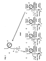
- FIG. 1 a shows by the reference numeral 10 a pressure measuring device for measuring the pressure in an extracorporeal circuit 20 of a dialysis machine.
- Reference numeral 30 denotes a blood pump located in the extracorporeal circuit 20.
- the reference numeral 40 denotes a clamp by means of which the tubing of the extracorporeal circuit 20 can be shut off.
- the pressure measuring device 10 is located between said clamp 40 and the blood pump 30 in the extracorporeal circuit 20 of a dialysis machine.
- the blood pump 30 promotes in the arrow direction according to FIG. 1a , which means in other words that the pressure measuring device 10 is located on the suction side of the blood pump 30.
- FIGS. 1b to 1e In normal operation can thus in the measuring chamber 12, in the FIGS. 1b to 1e is indicated, comparatively low pressures occur, in which the risk of decoupling of the membrane 13 of which also in the Figures 1b to 1 e shown pressure sensor 14 is increased.
- a disconnection that is to say a separation of the membrane 13 of the measuring chamber 12 from the pressure sensor 14 takes place and then a re-coupling of the membrane 13 of the measuring chamber 12 to the pressure sensor 14.
- This re-coupling further ensures good mechanical contact.
- the treatment can then be continued normally, whereas it is preferably interrupted during the uncoupling and coupling process. If a new connection is provided, for example because a predetermined period of time has expired or because a fault, for example the unwanted detachment of the diaphragm 13 of the measuring chamber 12 from the pressure sensor 14 is detected, is based on the state according to FIG.
- the enclosed negative pressure in the pump segment between the rollers obstructs or prevents the desired overpressure generation, according to the embodiment shown here, it is provided that starting the pump 30 or starting the build-up of the overpressure in the measuring chamber 12 takes place from a defined position of the rotor of the pump 30 out.
- step 1d means in other words that the membrane 13 of the measuring chamber 12 is separated from the pressure sensor 14. Due to the pressure prevailing in the measuring chamber 12 overpressure, the membrane 13 of the measuring chamber is curved outwardly, as in Figure 1d is indicated. Accordingly, a bulging of the membrane 13 of the measuring chamber 12 occurs.
- step 1e a new connection is performed, that is, the convex-shaped diaphragm 13 is applied to the pressure sensor 14.
- FIG. 2 shows an exemplary flowchart that the inventive reconnection of the membrane 13 of the measuring chamber 12 to the pressure sensor 14 describes.
- a variance analysis of the pressure signal can take place or, according to step 2.2, a check of the time profile of the pressure signal can be carried out. If these checks end with an error according to step 2.3, a new connection is initiated according to step 2.4.
- step 2.5 after the expiration of a time interval which, depending on the circumstances, can be typically about ⁇ 12 hours, the reconnection is carried out in accordance with step 2.4.
- the new connection begins with the terminal being opened, if necessary, according to step 2.6, and then, according to step 2.7, the blood pump 30 being stopped in a preferred position, which is reproduced here as a zero position.
- a waiting time of, for example, 2 seconds in accordance with step 2.8
- the pressure in the measuring chamber 12 is measured in step 2.9. If this is above a limit value or in a predetermined range, which in the exemplary embodiment illustrated here is between 20 mmHg and 100 mmHg, the diaphragm 13 of the measuring chamber 12 is decoupled from the pressure sensor 14.
- step 2.10 the clamp is closed (step 2.10) and the blood pump 30 is operated backwards (step 2.11).
- step 2.12 the rotation angle of the pump is checked. If there is an unwanted angle change, an error message is output. The reconnection can then be started again.
- the pressure is checked (step 2.13). If it is determined that the pressure is within a predetermined pressure range, the pump is stopped (step 2.14). If this is not the case, the pump will continue to operate.
- step 2.15 After stopping the blood pump 30, a predetermined period of time, here one second, is waited for (step 2.15) and then the pressure is measured (step 2.16). This pressure value is in FIG. 2 shown as P4.
- step 2.17 the so-called pressure dome is opened, which means in other words that the membrane 13 of the measuring chamber 12 is removed from the pressure sensor 14. Subsequently, a new connection is made ("pressure dome closes" in step 2.18) and then the pressure is checked (step 2.19). This pressure reading is in FIG. 2 marked with P3. If the pressure values P3 and P4 do not match within a tolerance band, an error message is output and the reconnection is restarted.
- the clamp is opened again (step 2.20) and then the pressure in the measuring chamber 12 is checked again (step 2.21).
- the determined pressure value is in FIG. 2 marked with P2. If the pressure P1 measured before closing the clamp does not match the pressure P2 within a tolerance band, an error is reported and the so-called coupling test is carried out.
- the treatment is continued, that is, the pump is started in its normal conveying direction and the treatment is continued (step 2.22).
- the present invention ensures that over a long period of time a decoupling of the membrane 13 of the measuring chamber 12 is excluded from the pressure sensor 14 or can be corrected even when prevailing in the extracorporeal circuit 20 negative pressure. This ensures reliable pressure measurements.
- the present invention is of particular importance when the pressure measurement takes place in a region which, in normal operation, lies on the negative pressure side, that is to say on the suction side of a pump and in which a negative pressure can prevail even when the liquid pump is stopped.
- the invention is not limited thereto and also includes cases in which the pressure measuring device is located on the pressure side of a pump.
- the method according to the invention or the device according to the invention can be used, for example, in a multifunctional device for the treatment of acute kidney diseases and / or for use in liver support and / or for use in various therapeutic apheresis methods. Other applications are conceivable.
- the pressure sensor 14, like the measuring chamber 12, can be designed with a membrane to which the membrane 13 of the measuring chamber 12 rests during normal operation. It is conceivable, for example, an arrangement as shown in the US 5,614,677 is known.
Description
Die vorliegende Erfindung betrifft ein Verfahren zum Betrieb einer Druckmesseinrichtung zur Messung des Druckes in einem fluiddurchströmten System, insbesondere in einem extrakorporalen Kreislauf eines medizinischen Gerätes, wobei die Druckmesseinrichtung eine durch eine flexible Membran begrenzte Messkammer, die im Betrieb des Systems von Fluid durchströmt wird oder mit Fluid gefüllt ist, sowie einen Drucksensor aufweist, der zum Zwecke der Druckmessung mit der Membran in Verbindung steht.The present invention relates to a method for operating a pressure measuring device for measuring the pressure in a fluid-flow system, in particular in an extracorporeal circuit of a medical device, wherein the pressure measuring device limited by a flexible membrane measuring chamber, which is flowed through during operation of the system of fluid or with Fluid is filled, and having a pressure sensor which communicates with the diaphragm for the purpose of pressure measurement.
Ein derartiges Verfahren ist beispielsweise aus der
Um möglichst zu verhindern, dass es bei einem zu großen Unterdruck zu einer Ablösung der Membran kommt und sich dadurch verfälschte oder überhaupt keine Druckwerte mehr erhalten lassen, wird in der
Ein Verfahren zum Ankoppeln einer Pumpkammer an die Arbeitsfluidkammer einer Membranpumpe ist aus der
Aus der
In der sogenannten Akutdialyse erfolgt die Behandlung der Patienten anders als bei der Behandlung chronisch kranker Dialysepatienten, die sich alle zwei bis drei Tage ca. vier bis fünf Stunden einer Hämodialysebehandlung unterziehen müssen, nahezu kontinuierlich. Dabei kann es vorkommen, dass je nach Zustand des Patienten beispielsweise auf einer Intensivstation die Behandlung mehrere Tage ununterbrochen andauern kann. In einem solchen Fall muss dementsprechend über einen vergleichsweise langen Zeitraum sichergestellt werden, dass die Druckmesseinrichtung einwandfrei und zuverlässig arbeitet.In so-called acute dialysis, the treatment of patients takes place, unlike in the treatment of chronically ill dialysis patients, who have to undergo hemodialysis treatment for about four to five hours every two to three days, almost continuously. It may happen that, depending on the condition of the patient, for example, in an intensive care unit, the treatment can last for several days without interruption. In such a case, it must therefore be ensured over a comparatively long period of time that the pressure measuring device operates properly and reliably.
Der vorliegenden Erfindung liegt daher die Aufgabe zugrunde, ein Verfahren der eingangs genannten Art dahingehend weiterzubilden, dass die Druckerfassung auch über einen langen Zeitraum zuverlässig erfolgt.The present invention is therefore the object of developing a method of the type mentioned in that the pressure detection is reliable even over a long period.
Diese Aufgabe wird durch ein Verfahren mit den Merkmalen des Anspruchs 1 gelöst.This object is achieved by a method having the features of claim 1.
Danach ist vorgesehen, dass das Verfahren die folgenden, kein Zutun des Personals erfordernden Schritte umfaßt:
- a. Erhöhung des Druckes in der Messkammer auf einen Druckwert, bei dem die Membran im nicht mit dem Drucksensor in Verbindung stehenden Zustand relativ zur Messkammer zumindest geringfügig nach außen gewölbt ist, oder Ermittlung eines solchen Druckwertes,
- b. Trennen der Membran der Messkammer von dem Drucksensor,
- c. Zusammenführen der Membran der Messkammer und des Drucksensors derart, dass die Membran der Messkammer an dem Drucksensor anliegt und
- d. Wiederholen der Schritte a. bis c. in vorbestimmten Zeitintervallen und/oder bei Auftreten eines Fehlerfalls.
- a. Increasing the pressure in the measuring chamber to a pressure value at which the diaphragm is relatively in the state not connected to the pressure sensor is curved at least slightly outward to the measuring chamber, or determination of such a pressure value,
- b. Separating the membrane of the measuring chamber from the pressure sensor,
- c. Merging the membrane of the measuring chamber and the pressure sensor such that the membrane of the measuring chamber rests against the pressure sensor and
- d. Repeat steps a. to c. at predetermined time intervals and / or when an error occurs.
Erfindungsgemäß ist somit vorgesehen, dass in periodischen Zeitabständen oder bei Auftreten eines Fehlerfalls, d. h. im Bedarfsfall eine mechanische Neuankopplung der Messkammer bzw. deren Membran an dem Drucksensor erfolgt.According to the invention, it is thus provided that at periodic intervals or when an error occurs, ie. H. If necessary, a mechanical reconnection of the measuring chamber or its membrane takes place on the pressure sensor.
Um eine erneute Ankopplung zuverlässig durchführen zu können, das heißt die Membran der Messkammer korrekt an den Drucksensor anlegen zu können, ist erfindungsgemäß vorgesehen, einen derartigen Überdruck in der Messkammer zu erzeugen, dass deren Membran zumindest geringfügig nach außen, das heißt konvex ausgewölbt ist. In diesem Zustand kann eine zuverlässige Kopplung der Membran mit dem Drucksensor erfolgen. Andernfalls besteht die Gefahr, dass die Membran durch einen Unterdruck bei geöffneter Druckmesseinrichtung nach innen gezogen, das heißt konkav verformt wird, was zur Folge hat, dass sich nach der Neuankopplung die Druckmessung unter Umständen verschlechtert bzw. ausfällt.In order to reliably perform a new coupling, that is, to be able to apply the membrane of the measuring chamber correctly to the pressure sensor, the invention provides to generate such an overpressure in the measuring chamber, that the membrane is at least slightly outwardly, that is convexly bulged. In this state, a reliable coupling of the membrane can be done with the pressure sensor. Otherwise, there is a risk that the membrane is pulled inward by a negative pressure with open pressure measuring device, that is concave deformed, with the result that the pressure measurement may deteriorate or fail after the reconnection.
Durch die Automatisierung des Ablaufs der Verfahrensschritte gemäß Anspruch 1 und die damit verbundene zyklische Wiederholung bzw. das Triggern der Verfahrensschritte a. bis c. bei erkennbaren Problemen mit der Druckmessung, z. B. durch einen Ankoppeltest oder durch Analyse der Druckpulsvarianz am Sensor oder auch anderen Fehlerfällen ist die korrekte Ankopplung über den gesamten Behandlungszeitraum gewährleistet. Ein Versagen der Druckmessung oder eine sonst über einen längeren Zeitraum zu beobachtende Drift zu höheren Drücken hin, kann erfindungsgemäß verhindert werden. Mittels des erfindungsgemäßen Verfahrens lässt sich jederzeit ein hinreichender Überdruck in der Messkammer erzeugen, wodurch eine gute Verbindung mit dem Drucksensor erreicht wird. Abgesehen davon, ist das Verfahren sicher zu jedem Zeit- und Druckpunkt sowie schnell durchführbar.By automating the sequence of the method steps according to claim 1 and the associated cyclic repetition or the triggering of the method steps a. to c. with recognizable problems with the pressure measurement, z. B. by a coupling test or by analysis of the pressure pulse variance on the sensor or other error cases, the correct coupling over the entire treatment period is guaranteed. Failure of the pressure measurement or otherwise observed over a longer period of drift towards higher pressures can be prevented according to the invention. By means of the method according to the invention, a sufficient overpressure in the measuring chamber can be generated at all times, whereby a good connection with the pressure sensor is achieved. Apart from this, the procedure is safe at any time and pressure point as well as fast to perform.
In bevorzugter Ausgestaltung des Verfahrens ist vorgesehen, dass die Erhöhung des Druckes in der Messkammer mittels einer im System befindlichen Pumpe, insbesondere mittels einer im extrakorporalen Kreislauf befindlichen Blutpumpe, durchgeführt wird. Dabei kann vorgesehen sein, dass die Pumpe zum Zwecke der Erhöhung des Druckes in der Messkammer im Rückwärtslauf betrieben wird, das heißt in einer Förderrichtung, die der Förderrichtung im normalen Betrieb entgegengesetzt ist. Dies ist jedoch kein zwingendes Merkmal. Befindet sich die Druckmesseinrichtung in dem Bereich, der im normalen Betrieb der Pumpe auf der Pumpendruckseite liegt, ist eine Umkehr der Förderrichtung der Pumpe nicht erforderlich.In a preferred embodiment of the method, it is provided that the increase in the pressure in the measuring chamber is carried out by means of a pump located in the system, in particular by means of a blood pump located in the extracorporeal circuit. It can be provided that the pump is operated for the purpose of increasing the pressure in the measuring chamber in reverse, that is in a conveying direction which is opposite to the conveying direction in normal operation. However, this is not a mandatory feature. If the pressure measuring device is located in the region which is located on the pump pressure side during normal operation of the pump, a reversal of the direction of flow of the pump is not required.
In weiterer Ausgestaltung der Erfindung ist vorgesehen, dass vor oder während des Betriebes der Pumpe eine Klemme geschlossen wird, um die Durchströmung des Systems zu verhindern oder der Durchströmung einen erhöhten Widerstand entgegenzusetzen, wobei die Klemme derart angeordnet ist, dass sich die Messkammer zwischen Pumpe und Klemme befindet.In a further embodiment of the invention it is provided that before or during operation of the pump, a terminal is closed to prevent the flow through the system or the flow to oppose increased resistance, wherein the terminal is arranged such that the measuring chamber between the pump and Terminal is located.
In weiterer Ausgestaltung der Erfindung ist vorgesehen, dass Schritt a. vor Schritt b. oder auch Schritt b. vor Schritt a. ausgeführt wird. Vorzugsweise ist vorgesehen, dass die Erhöhung des Druckes der Messkammer auf einen Druckwert bzw. die Feststellung eines solchen Druckwertes erfolgt, bevor die Membran der Messkammer von dem Drucksensor entfernt wird. Grundsätzlich ist jedoch ebenfalls denkbar, zunächst die Membran der Messkammer von dem Drucksensor zu entfernen und sodann die Erhöhung oder Feststellung des Druckes in der Messkammer vorzunehmen. In diesem Fall könnte vorgesehen sein, dass ein vorgegebenes Volumen des Fluids in die Meßkammer gefördert wird.In a further embodiment of the invention, it is provided that step a. before step b. or also step b. before step a. is performed. It is preferably provided that the increase in the pressure of the measuring chamber to a pressure value or the determination of such a pressure value takes place before the membrane of the measuring chamber is removed from the pressure sensor. In principle, however, it is also conceivable first to remove the membrane of the measuring chamber from the pressure sensor and then to increase or detect the pressure in the measuring chamber. In this case it could be provided that a predetermined volume of the fluid is conveyed into the measuring chamber.
Gemäß einer weiteren Ausgestaltung der Erfindung ist vorgesehen, dass die Erhöhung des Druckes vorgenommen wird, bis ein vorgegebener Druckwert oder Druckwertbereich erreicht ist. Ist dies nicht der Fall, kann vorgesehen sein, dass die Pumpe weiter fördert, bis der Druckwert erreicht ist. Ist der Druckwert erreicht, kann weiterhin vorgesehen sein, dass die Pumpe angehalten wird.According to a further embodiment of the invention, it is provided that the increase in the pressure is carried out until a predetermined pressure value or Pressure value range is reached. If this is not the case, it can be provided that the pump further promotes until the pressure value is reached. Once the pressure has been reached, it can further be provided that the pump is stopped.
In weiterer Ausgestaltung der Erfindung ist vorgesehen, dass die Pumpe zum Zwecke der Druckerhöhung ausgehend von einer definierten Stellung des Förderorgans der Pumpe erfolgt. Insbesondere im Falle der Verwendung einer peristaltischen Pumpe ist es sinnvoll, das Anfahren eines Überdrucks vorteilhaft aus einer definierten Lage des Rotors heraus durchzuführen, damit der eingeschlossene Unterdruck im Pumpsegment zwischen den Rollen nicht die gewünschte Überdruckerzeugung verhindert oder behindert.In a further embodiment of the invention, it is provided that the pump takes place for the purpose of pressure increase, starting from a defined position of the conveying member of the pump. In particular, in the case of using a peristaltic pump, it makes sense to advantageously perform the start of an overpressure from a defined position of the rotor, so that the trapped negative pressure in the pump segment between the rollers does not prevent or hinder the desired overpressure generation.
In weiterer Ausgestaltung der Erfindung ist vorgesehen, dass die Pumpe zum Zwecke der Druckerhöhung solange fördert, bis ein vorgegebenes Fördervolumen oder eine vorgegebene Stellung des Förderorgans der Pumpe erreicht ist. Denkbar ist es beispielsweise, im Falle der genannten peristaltischen Pumpe den Drehwinkel des Rotors zu prüfen und die Förderung zu stoppen, sobald ein bestimmter Drehwinkel erreicht ist.In a further embodiment of the invention, it is provided that the pump for the purpose of increasing the pressure promotes until a predetermined delivery volume or a predetermined position of the conveying member of the pump is reached. It is conceivable, for example, in the case of said peristaltic pump to check the angle of rotation of the rotor and to stop the promotion, as soon as a certain angle of rotation is reached.
In weiterer Ausgestaltung der Erfindung ist vorgesehen, dass vor Schritt b., das heißt vor der Trennung der Membran der Messkammer von dem Drucksensor und nach Schritt c., das heißt nach der Neukonnektierung jeweils der Druck in der Messkammer gemessen wird und dass eine Fehlermeldung ausgegeben wird, wenn die beiden Druckwerte nicht übereinstimmen oder nicht in einem vorgegebenen Bereich liegen. Denkbar ist es, dass die genannten Druckmessungen unmittelbar vor dem Abkoppeln und nach der Neuankopplung durchgeführt werden.In a further embodiment of the invention, it is provided that before step b., That is, before the separation of the membrane of the measuring chamber of the pressure sensor and after step c., That is, after reconnecting each of the pressure in the measuring chamber is measured and that issued an error message when the two pressure values do not match or are not in a predetermined range. It is conceivable that the said pressure measurements are carried out immediately before uncoupling and after the new connection.
In weiterer Ausgestaltung der Erfindung ist vorgesehen, dass die Klemme geöffnet wird, wenn die Membran der Messkammer und der Drucksensor gemäß Schritt c. zusammengeführt sind.In a further embodiment of the invention it is provided that the terminal is opened when the membrane of the measuring chamber and the pressure sensor according to step c. are merged.
Denkbar ist es, vor dem Schließen der Klemme, gegen die die Pumpe fördert, und nach dem genannten Öffnen der Klemme jeweils den Druck in der Messkammer zu messen und eine Fehlermeldung auszugeben, wenn die beiden Druckwerte nicht übereinstimmen oder nicht in einem vorgegebenen Bereich liegen.It is conceivable to measure the pressure in the measuring chamber and to issue an error message before closing the clamp, against which the pump delivers, and after the opening of the clamp, if the two pressure values do not coincide or are not in a predetermined range.
In weiterer Ausgestaltung der Erfindung ist vorgesehen, dass der Drucksensor nach dem Trennen der Membran der Messkammer von dem Drucksensor gemäß Schritt b. und vor dem Zusammenführen der Membran der Messkammer und des Drucksensors gemäß Schritt c. einer Funktionsüberprüfung unterzogen wird. Durch das zyklische Auffahren der Druckmesseinrichtung kann somit gegebenenfalls ein erforderlicher Test des Drucksensors durchgeführt werden. Der Drucksensor kann im nicht angekoppelten Zustand kurze Zeit gegen Umgebung oder gegen einen Referenzdruck geschaltet werden und auf seinen Nullpunkt bzw. auf einen Referenzpunkt und damit auf seine Funktion geprüft werden.In a further embodiment of the invention, it is provided that the pressure sensor after separating the membrane of the measuring chamber from the pressure sensor according to step b. and before merging the membrane of the measuring chamber and the pressure sensor according to step c. is subjected to a functional check. By cyclically ascending the pressure measuring device, a required test of the pressure sensor can thus optionally be carried out. The pressure sensor can be switched in the uncoupled state for a short time against environment or against a reference pressure and tested for its zero point or on a reference point and thus on its function.
Die vorliegende Erfindung betrifft des weiteren eine Vorrichtung mit den Merkmalen des Anspruchs 14.The present invention further relates to a device having the features of
Danach sind erste Mittel zur Erhöhung des Druckes in der Messkammer auf einen Druckwert, bei dem die Membran im nicht mit dem Drucksensor in Verbindung stehenden Zustand relativ zur Messkammer zumindest geringfügig nach außen gewölbt ist, oder zur Ermittlung eines solchen Druckwertes vorgesehen. Die Vorrichtung weist des weiteren zweite Mittel zum Trennen der Membran der Messkammer von dem Drucksensor sowie dritte Mittel zum Zusammenführen der Membran der Messkammer und des Drucksensors derart auf, dass die Membran der Messkammer an dem Drucksensor anliegt. Die Vorrichtung weist des weiteren eine Steuereinheit auf, die derart ausgeführt ist, dass sie die ersten, zweiten und dritten Mittel entsprechend ihrer vorgesehenen Betriebsweise in vorbestimmten Zeitintervallen und/oder bei Auftreten eines Fehlerfalls ohne Intervention des Personals ansteuert.Thereafter, first means for increasing the pressure in the measuring chamber to a pressure value at which the membrane is at least slightly curved outwards relative to the measuring chamber in the non-pressure-related state, or to determine such a pressure value provided. The device further comprises second means for separating the membrane of the measuring chamber from the pressure sensor and third means for merging the membrane of the measuring chamber and the pressure sensor such that the membrane of the measuring chamber rests against the pressure sensor. The device further comprises a control unit which is designed such that it controls the first, second and third means according to their intended operation at predetermined time intervals and / or in the event of an error case without intervention of the staff.
Die Vorrichtung weist vorzugsweise Mittel zur Durchführung der Verfahrensschritte gemäß einem der Ansprüche 1 bis 13 auf.The device preferably has means for carrying out the method steps according to one of claims 1 to 13.
Bevorzugte Ausgestaltungen der Vorrichtung sind Gegenstand der Ansprüche 15 bis 27.Preferred embodiments of the device are subject matter of claims 15 to 27.
In einer bevorzugten Ausgestaltung der Erfindung ist die Messkammer als Disposable ausgeführt oder Bestandteil eines Disposables. Denkbar ist es somit, die Messkammer nach der Behandlung eines Patienten auszutauschen. Vorzugsweise ist weiter vorgesehen, dass der Drucksensor als wiederverwendbares Teil oder als Bestandteil einer wiederverwendbaren Einheit ausgeführt ist, das heißt jedenfalls nicht nach jeder Behandlung, sondern nur im Bedarfsfalle ausgetauscht wird.In a preferred embodiment of the invention, the measuring chamber is designed as a disposable or part of a disposable. It is thus conceivable to exchange the measuring chamber after the treatment of a patient. Preferably, it is further provided that the pressure sensor is designed as a reusable part or as part of a reusable unit, that is at least not after each treatment, but only in case of need replaced.
Die vorliegende Erfindung betrifft des weiteren ein Gerät, insbesondere ein medizinisches Gerät mit den Merkmalen des Anspruchs 28. Bei dem Gerät kann es sich beispielsweise um ein Dialysegerät, um ein Gerät zur Leberunterstützung oder um ein Gerät zur Apheresebehandlung handeln.The present invention further relates to a device, in particular a medical device having the features of claim 28. The device may be, for example, a dialysis machine, a liver support device or an apheresis treatment device.
Die vorliegende Erfindung betrifft des weiteren die Verwendung einer durch eine flexible Membran begrenzten Messkammer die vorzugsweise einen Fluidzufluss und einen Fluidabfluss aufweist, als Bestandteil einer Druckmesseinrichtung in einem Verfahren gemäß einem der Ansprüche 1 bis 13 und/oder in einer Vorrichtung gemäß einem der Ansprüche 14 bis 27 und/oder in einem Gerät gemäß einem der Ansprüche 28 oder 29.The present invention further relates to the use of a limited by a flexible membrane measuring chamber preferably having a fluid inlet and a fluid drain, as part of a pressure measuring device in a method according to one of claims 1 to 13 and / or in an apparatus according to any one of
Wie oben ausgeführt, kann vorgesehen sein, dass die Messkammer als Disposable ausgeführt ist und nach Abschluß vorzugsweise einer Behandlung verworfen wird.As stated above, it can be provided that the measuring chamber is designed as a disposable and after completion preferably a treatment is discarded.
Weitere Einzelheiten und Vorteile der Erfindung werden anhand eines in der Zeichnung dargestellten Ausführungsbeispiels näher erläutert. Dabei zeigen:
- Figur 1:
- eine schematische Darstellung des Ablaufes der Neuankopplung der Membran der Messkammer an den Drucksensor gemäß der vorliegenden Erfindung und
- Figur 2:
- einen Flußplan zur Durchführung der Neuankopplung der Membran der Messkammer an den Drucksensor gemäß der vorliegenden Erfindung, wobei alle angegebenen Zahlenwerte nur Beispielcharakter haben.
- FIG. 1:
- a schematic representation of the process of reconnecting the membrane of the measuring chamber to the pressure sensor according to the present invention and
- FIG. 2:
- a flow chart for performing the reconnection of the membrane of the measuring chamber to the pressure sensor according to the present invention, all numerical values are given by way of example only.
Wie dies aus
Gemäß dem hier dargestellten Ausführungsbeispiel ist vorgesehen, dass in vorbestimmten Zeitintervallen, das heißt periodisch oder im Fehlerfall eine Abkopplung, das heißt eine Trennung der Membran 13 der Messkammer 12 von dem Drucksensor 14 erfolgt und anschließend eine Neuankopplung der Membran 13 der Messkammer 12 an den Drucksensor 14. Durch diese Neuankopplung wird ein guter mechanischer Kontakt weiter sichergestellt. Die Behandlung kann dann normal weitergeführt werden, wohingegen sie während des Ab- und Ankoppelvorgangs vorzugsweise unterbrochen ist. Sofern eine Neuankopplung vorgesehen ist, etwa weil eine vorbestimmte Zeitspanne abgelaufen ist oder weil ein Fehlerfall, beispielsweise die ungewollte Ablösung der Membran 13 der Messkammer 12 von dem Drucksensor 14 festgestellt wird, wird ausgehend von dem Zustand gemäß
Um zu verhindern, dass im Falle einer peristaltischen Pumpe der eingeschlossene Unterdruck im Pumpsegment zwischen den Rollen die gewünschte Überdruckerzeugung behindert oder verhindert, ist gemäß dem hier dargestellten Ausführungsbeispiel vorgesehen, dass das Anfahren der Pumpe 30 bzw. das Beginnen des Aufbaus des Überdrucks in der Messkammer 12 aus einer definierten Lage des Rotors der Pumpe 30 heraus erfolgt.In order to prevent that in the case of a peristaltic pump, the enclosed negative pressure in the pump segment between the rollers obstructs or prevents the desired overpressure generation, according to the embodiment shown here, it is provided that starting the
Ist der gewünschte Druckwert in der Messkammer 12 erreicht, wird gemäß Schritt 1d die Druckmesseinheit 10 geöffnet, was mit anderen Worten bedeutet, dass die Membran 13 der Messkammer 12 von dem Drucksensor 14 getrennt wird. Aufgrund des in der Messkammer 12 herrschenden Überdruckes wird die Membran 13 der Messkammer nach außen gewölbt, wie dies in
Sodann wird gemäß Schritt 1e eine Neuankopplung durchgeführt, das heißt die konvex verformte Membran 13 an den Drucksensor 14 angelegt.Then, according to step 1e, a new connection is performed, that is, the convex-shaped
Nach Durchführung eines Ankopplungstestes, bei dem festgestellt werden kann, ob die Ankopplung zuverlässig erfolgt ist, kann vorgesehen sein, dass die Klemme 40 wieder geöffnet wird und die Blutpumpe 30 wieder in ihrer normalen Förderrichtung gemäß
Alternativ oder zusätzlich kann vorgesehen sein, dass gemäß Schritt 2.5 nach Ablauf eines Zeitintervalls, dass abhängig von der Gegebenheit bei typisch ca. ≥ 12 Stunden liegen kann, die Neuankopplung gemäß Schritt 2.4 durchgeführt wird.Alternatively or additionally, it may be provided that, according to step 2.5, after the expiration of a time interval which, depending on the circumstances, can be typically about ≥ 12 hours, the reconnection is carried out in accordance with step 2.4.
Die Neuankopplung beginnt damit, dass gemäß Schritt 2.6 die Klemme, sofern nötig, geöffnet wird und dass anschließend gemäß Schritt 2.7 die Blutpumpe 30 bei einer Vorzugsstellung, die hier als Nullstellung wiedergegeben ist, gestoppt wird. Nach Ablauf einer Wartezeit von beispielsweise 2 Sekunden gemäß Schritt 2.8 wird in Schritt 2.9 der Druck in der Messkammer 12 gemessen. Liegt dieser oberhalb eines Grenzwertes bzw. in einem vorgegebenen Bereich, der in dem hier dargestellten Ausführungsbeispiel zwischen 20 mmHg und 100 mmHg liegt, wird eine Abkopplung der Membran 13 der Messkammer 12 von dem Drucksensor 14 durchgeführt.The new connection begins with the terminal being opened, if necessary, according to step 2.6, and then, according to step 2.7, the
Ist dies jedoch nicht der Fall, wird festgestellt, dass eine Druckerhöhung in der Messkammer 12 vorzunehmen ist. In diesem Fall wird die Klemme geschlossen (Schritt 2.10) und die Blutpumpe 30 rückwärts betrieben (Schritt 2.11). In Schritt 2.12 wird der Drehwinkel der Pumpe geprüft. Kommt es zu einer nicht gewünschten Winkeländerung, wird eine Fehlermeldung ausgegeben. Die Neuankopplung kann dann erneut begonnen werden.If this is not the case, it is determined that an increase in pressure in the measuring
Nach Anlaufen der Pumpe 30 wird der Druck geprüft (Schritt 2.13). Wird festgestellt, dass der Druck in einem vorgegebenen Druckwertbereich liegt, wird die Pumpe gestoppt (Schritt 2.14). Ist dies nicht der Fall, wird die Pumpe weiter betrieben.After starting the
Nach dem Anhalten der Blutpumpe 30 wird eine vorbestimmte Zeitspanne, hier eine Sekunde, abgewartet (Schritt 2.15) und sodann der Druck gemessen (Schritt 2.16). Dieser Druckwert ist in
Stimmen beide Druckwerte jedoch innerhalb des Toleranzbandes überein, wird die Behandlung fortgesetzt, das heißt die Pumpe in ihrer normalen Förderrichtung in Betrieb gesetzt und die Behandlung fortgeführt (Schritt 2.22).However, if both pressure values are within the tolerance band, the treatment is continued, that is, the pump is started in its normal conveying direction and the treatment is continued (step 2.22).
Durch die vorliegende Erfindung wird sichergestellt, dass über einen langen Zeitraum hin ein Abkoppeln der Membran 13 der Messkammer 12 von dem Drucksensor 14 ausgeschlossen wird bzw. auch bei im extrakorporalen Kreislauf 20 herrschenden Unterdruck korrigiert werden kann. Dadurch werden zuverlässige Druckmessungen sichergestellt.The present invention ensures that over a long period of time a decoupling of the
Die vorliegende Erfindung ist insbesondere dann von Bedeutung, wenn die Druckmessung in einem Bereich erfolgt, der im normalen Betrieb auf der Unterdruckseite, das heißt auf der Saugseite einer Pumpe liegt und in den auch bei gestoppter Flüssigkeitspumpe ein negativer Druck herrschen kann. Die Erfindung ist jedoch darauf nicht beschränkt und umfasst auch Fälle, in denen die Druckmesseinrichtung auf der Druckseite einer Pumpe liegt.The present invention is of particular importance when the pressure measurement takes place in a region which, in normal operation, lies on the negative pressure side, that is to say on the suction side of a pump and in which a negative pressure can prevail even when the liquid pump is stopped. However, the invention is not limited thereto and also includes cases in which the pressure measuring device is located on the pressure side of a pump.
Das erfindungsgemäße Verfahren bzw. die erfindungsgemäße Vorrichtung können beispielsweise in einem multifunktionalen Gerät zur Behandlung akuter Nierenerkrankungen und/oder zum Einsatz in einer Leberunterstützung und/oder zur Anwendung bei verschiedenen therapeutischen Aphereseverfahren eingesetzt werden. Auch andere Anwendungsfälle sind denkbar.The method according to the invention or the device according to the invention can be used, for example, in a multifunctional device for the treatment of acute kidney diseases and / or for use in liver support and / or for use in various therapeutic apheresis methods. Other applications are conceivable.
Der Drucksensor 14 kann wie auch die Messkammer 12 mit einer Membran ausgeführt sein, an die im normalen Betrieb die Membran 13 der Messkammer 12 anliegt. Denkbar ist beispielsweise eine Anordnung, wie sie aus der
Claims (31)
- A method for the operation of a pressure measuring device (10) for the measurement of the pressure in a system through which fluid flows, in particular in an extracorporeal circuit (20) of a medical unit, with the pressure measuring device (10) having a measuring chamber (12) which is bounded by a flexible membrane (13), through which fluid flows in the operation of the system or which is filled with fluid and also having a pressure sensor (14) connected to the membrane (13) for the purpose of pressure measurement,
characterized in that
the method includes the following steps not requiring any intervention of the staff:a. increasing the pressure in the measuring chamber (12) to a pressure value at which the membrane (13) is at least slightly outwardly curved relative to the measuring chamber (12) in the state not connected to the pressure sensor (14) or determining such a pressure value;b. separating the membrane (13) of the measuring chamber (12) from the pressure sensor (14);c. joining together the membrane (13) of the measuring chamber (12) and of the pressure sensor (14) such that the membrane (13) of the measuring chamber (12) contacts the pressure sensor (14); andd. repeating the steps a. to c. at predetermined intervals and/or on the occurrence of an error case. - A method in accordance with claim 1, characterized in that the increase in the pressure in the measuring chamber (12) is carried out by means of a pump (30) located in the system, in particular by means of a blood pump (30) located in the extracorporeal circuit (20).
- A method in accordance with claim 2, characterized in that the pump (30) is operated in reverse operation for the purpose of increasing the pressure in the measuring chamber (12).
- A method in accordance with either of claims 2 or 3, characterized in that a clamp (40) is closed before or after the operation of the pump (30) to prevent the system being flowed through or to set an increased resistance against the throughflow, with the clamp (40) being arranged such that the measuring chamber (12) is located between the pump (30) and the clamp (40).
- A method in accordance with any one of the preceding claims, characterized in that step a. is carried out before step b. or step b. is carried out before step a.
- A method in accordance with one of the preceding claims, characterized in that the increase of the pressure is carried out until a predetermined pressure value or pressure value range has been reached.
- A method in accordance with claim 6 as well as in accordance with one of the claims 2 to 5, characterized in that the pump (30) is stopped when the preset pressure value or pressure value range has been reached.
- A method in accordance with one of the claims 2 to 7, characterized in that the pump (30) is set into operation for the purpose of the pressure increase, starting from a defined position of the conveying member of the pump (30).
- A method in accordance with one of the claims 2 to 8, characterized in that the pump (30) conveys so long for the purpose of the pressure increase until a preset conveying volume has been reached or until a preset position of the conveying member of the pump (30) has been reached.
- A method in accordance with one of the preceding claims, characterized in that the pressure in the measuring chamber (12) is measured before step b. and after step c.; and in that an error message is output if the pressure values do not coincide or if they are not in a preset range.
- A method in accordance with one of the claims 4 to 10, characterized in that the clamp (40) is opened when the membrane (13) of the measuring chamber (12) and the pressure sensor (14) are joined together in accordance with step c.
- A method in accordance with claim 11, characterized in that the pressure in the measuring chamber (12) is measured before the closing of the clamp (40) and after the opening of the clamp (40); and in that an error message is output if the pressure values do not coincide or if they are not in a preset range.
- A method in accordance with one of the preceding claims, characterized in that the pressure sensor (14) is subjected to a function test after the separation of the membrane (13) of the measuring chamber (12) from the pressure sensor (14) in accordance with step b. and before the joining together of the membrane (13) of the measuring chamber (12) and of the pressure sensor (14) in accordance with step c.
- An apparatus having at least one pressure measuring device (10) for the measurement of the pressure in a system through which fluid flows, in particular in an extracorporeal circuit (20) of a medical unit, with the pressure measuring device (10) having at least one measuring chamber (12) which is bounded by a flexible membrane (13), through which fluid flows in the operation of the system or which is filled with fluid and also having at least one pressure sensor (14) connected to the membrane (13) for the purpose of pressure measurement, wherein the apparatus has first means for increasing the pressure in the measuring chamber (12) to a pressure value at which the membrane (13) is at least slightly outwardly curved relative to the measuring chamber (12) in the state not connected to the pressure sensor (14), or for determining such a pressure value; second means for separating the membrane (13) of the measuring chamber (12) from the pressure sensor (14); and third means for joining together the membrane (13) of the measuring chamber (12) and of the pressure sensor (14) which are formed such that the membrane (13) of the measuring chamber (12) contacts the pressure sensor (14),
characterized in that
the apparatus has as a control unit which is made such that it controls the first, second and third means at predetermined time intervals and/or on the occurrence of an error case without intervention of the staff. - An apparatus in accordance with claim 14, characterized in that the first means include a pump (30), in particular a blood pump (30) located in the extracorporeal circuit (20).
- An apparatus in accordance with claim 15, characterized in that the control unit is made such that it controls the pump (30) for the purpose of increasing the pressure in the measuring chamber (12) in reverse operation.
- An apparatus in accordance with one of the claims 14 to 16, characterized in that the first means include a clamp (40) to prevent a throughflow of the system or to set an increased resistance against the throughflow of the system, with the clamp (40) being arranged such that the measuring chamber (12) is located between the pump (30) and the clamp (40), and wherein the control unit is made such that it initiates the partial or complete closing of the clamp (40) before or while the pump (30) runs for the purpose of increasing the pressure in the measuring chamber (12).
- An apparatus in accordance with one of the claims 14 to 17, characterized in that the control unit is made such that it controls the first and second means such that the first means are operated before the second means or the second means are operated before the first means.
- An apparatus in accordance with one of the claims 14 to 18, characterized in that the control unit is made such that it initiates an increase in the pressure in the measuring chamber (12) by the first means until a preset pressure value or pressure value region has been reached.
- An apparatus in accordance with one of the claims 15 to 19, characterized in that the control unit is made such that it initiates the increase of the pressure in the measuring chamber (12) by the pump (30), starting from a defined position of the conveying member of the pump (30).
- An apparatus in accordance with one of the claims 15 to 20, characterized in that the control unit is made such that it initiates the increase of the pressure in the measuring chamber (12) by the pump (30) until a preset conveying volume has been reached or until a preset position of the conveying member of the pump (30) has been reached.
- An apparatus in accordance with one of the claims 14 to 21, characterized in that the control unit is made such that it in each case initiates a pressure measurement in the measuring chamber (12) before activation of the second means and after activation of the third means; and in that a device is provided for the outputting of an error message which is made such that it is activated by the control unit if the two pressure values do not coincide or are not in a preset range.
- An apparatus in accordance with one of the claims 14 to 22, characterized in that the control unit is made such that it initiates the opening of the clamp (40) after the membrane (13) of the measuring chamber (12) and the pressure sensor (14) have been joined together by the third means.
- An apparatus in accordance with one of the claims 17 to 23, characterized in that the control unit is made such that it in each case initiates a pressure measurement in the measuring chamber (12) before the closing of the clamp (40) and after the opening of the clamp (40); and in that a device is provided for the outputting of an error message which is made such that it is activated by the control unit if the two pressure values do not coincide or are not in a preset range.
- An apparatus in accordance with one of the claims 14 to 24, characterized in that the control unit is made such that it subjects the pressure sensor (14) to a function test after the activation of the second means and before the activation of the third means.
- An apparatus in accordance with one of the claims 14 to 25, characterized in that the measuring chamber (12) is made as a disposable product or is a component of a disposable product.
- An apparatus in accordance with one of the claims 14 to 26, characterized in that the pressure sensor (14) is made as a reusable part or as a component of a reusable unit.
- A unit, in particular a medical unit, comprising at least one apparatus in accordance with one of the claims 14 to 27.
- A unit in accordance with claim 28, characterized in that it is a dialyzer, a unit to support the liver or a unit for apheresis treatment.
- Use of a measuring chamber (12) bounded by a flexible membrane (13) and having a fluid inflow and a fluid outflow as a component of a pressure measuring device (10) in a method in accordance with one of the claims 1 to 13 and/or in an apparatus in accordance with one of the claims 14 to 27 and/or in a unit in accordance with one of the claims 28 or 29.
- Use in accordance with claim 30, characterized in that the measuring chamber (12) is made as a disposable product and is discarded after the conclusion of preferably one treatment.
Applications Claiming Priority (2)
| Application Number | Priority Date | Filing Date | Title |
|---|---|---|---|
| DE102008034154A DE102008034154B4 (en) | 2008-07-22 | 2008-07-22 | Method for operating a pressure measuring device, device with at least one pressure measuring device, device with such a device |
| PCT/EP2009/005292 WO2010009867A1 (en) | 2008-07-22 | 2009-07-21 | Method for operating a pressure measuring unit, apparatus having at least one pressure measuring unit, device having such an apparatus, and use of a measuring chamber |
Publications (2)
| Publication Number | Publication Date |
|---|---|
| EP2300073A1 EP2300073A1 (en) | 2011-03-30 |
| EP2300073B1 true EP2300073B1 (en) | 2013-05-29 |
Family
ID=41226188
Family Applications (1)
| Application Number | Title | Priority Date | Filing Date |
|---|---|---|---|
| EP09777340.2A Active EP2300073B1 (en) | 2008-07-22 | 2009-07-21 | Method for operating a pressure measuring unit, apparatus having at least one pressure measuring unit, device having such an apparatus, and use of a measuring chamber |
Country Status (6)
| Country | Link |
|---|---|
| US (1) | US8375797B2 (en) |
| EP (1) | EP2300073B1 (en) |
| JP (1) | JP5485991B2 (en) |
| CN (1) | CN102105181B (en) |
| DE (1) | DE102008034154B4 (en) |
| WO (1) | WO2010009867A1 (en) |
Families Citing this family (8)
| Publication number | Priority date | Publication date | Assignee | Title |
|---|---|---|---|---|
| US8092414B2 (en) | 2005-11-09 | 2012-01-10 | Nxstage Medical, Inc. | Diaphragm pressure pod for medical fluids |
| EP3524288A3 (en) | 2011-03-23 | 2019-11-20 | NxStage Medical Inc. | Peritoneal dialysis systems |
| US9861733B2 (en) | 2012-03-23 | 2018-01-09 | Nxstage Medical Inc. | Peritoneal dialysis systems, devices, and methods |
| US9551625B2 (en) | 2011-05-31 | 2017-01-24 | Nxstage Medical, Inc. | Pressure measurement devices, methods, and systems |
| CN104394899B (en) * | 2012-12-20 | 2017-04-05 | 甘布罗伦迪亚股份公司 | Blood dial bundle LMS connecting detection |
| JP6483874B1 (en) | 2018-01-18 | 2019-03-13 | 日機装株式会社 | Pressure detector adjustment device |
| US11872337B2 (en) | 2018-02-28 | 2024-01-16 | Nxstage Medical, Inc. | Fluid preparation and treatment devices methods and systems |
| CN108398203A (en) * | 2018-05-14 | 2018-08-14 | 苏州名列膜材料有限公司 | A kind of blocking solution test device and blocking solution test system |
Family Cites Families (28)
| Publication number | Priority date | Publication date | Assignee | Title |
|---|---|---|---|---|
| US4185641A (en) * | 1978-08-23 | 1980-01-29 | Hewlett-Packard Company | Pressure dome |
| JPS5957946U (en) * | 1982-10-08 | 1984-04-16 | 横河電機株式会社 | Negative pressure monitor |
| JPH04346044A (en) * | 1991-05-23 | 1992-12-01 | Kanegafuchi Chem Ind Co Ltd | Pillow-type pressure sensor |
| DE4419593A1 (en) * | 1994-06-03 | 1995-12-07 | Fresenius Ag | Device for measuring the pressure of a medium |
| FR2724321A1 (en) * | 1994-09-14 | 1996-03-15 | Hospal Ind | DEVICE FOR MEASURING THE PRESSURE OF A LIQUID AND METHOD FOR ADJUSTING SUCH A DEVICE |
| JPH08166301A (en) * | 1994-12-13 | 1996-06-25 | Kanegafuchi Chem Ind Co Ltd | Pillow-shaped pressure detector |
| DE19638813C1 (en) * | 1996-09-20 | 1998-03-05 | Sican F & E Gmbh Sibet | Measuring device for medical applications with an intracorporeally usable sensor element and method for its production |
| DE19700466A1 (en) * | 1997-01-09 | 1998-07-16 | Polaschegg Hans Dietrich Dr | Hemodiafiltration device and method |
| EP0941132A2 (en) | 1997-09-12 | 1999-09-15 | COBE Laboratories, Inc. | Extracorporeal blood processing system |
| US6280406B1 (en) * | 1997-09-12 | 2001-08-28 | Gambro, Inc | Extracorporeal blood processing system |
| DE19814101A1 (en) | 1998-03-30 | 1999-10-14 | Fresenius Medical Care De Gmbh | Process for the airtight connection of two membranes |
| US6044691A (en) * | 1998-08-26 | 2000-04-04 | Aksys, Ltd. | Blood tubing set integrity tests for extracorporeal circuits |
| DE10032616A1 (en) | 2000-07-08 | 2002-01-24 | Mhm Harzbecher Medizintechnik | System element for transducer connection in pressure-monitoring sets for extracorporeal circuits, e.g. in open-heart surgery, has a measuring chamber with a membrane which fits in a special channel in the housing |
| FR2817756B1 (en) * | 2000-12-08 | 2008-10-31 | Hospal Internat Marketing Man | DEVICE FOR PRESSURE MEASUREMENT COMPRISING A MOTORIZED EFFORT SENSOR |
| FR2817755B1 (en) * | 2000-12-08 | 2003-01-24 | Hospal Internat Marketing Man | DEVICE FOR MEASURING NEGATIVE PRESSURES IN AN EXTRACORPOREAL BLOOD CIRCUIT |
| US6622542B2 (en) * | 2001-03-20 | 2003-09-23 | Therox, Inc. | Bubble detector and method of use thereof |
| DE10201109C1 (en) * | 2002-01-15 | 2003-01-23 | Fresenius Medical Care De Gmbh | Detecting leak in liquid system of blood treatment system involves deriving leakage rate from change in pressure in defined intervals, driving leakage volume from leakage rate |
| DE10230413B4 (en) * | 2002-07-06 | 2004-07-22 | Fresenius Medical Care Deutschland Gmbh | Device for determining the blood volume during extracorporeal blood treatment |
| DE10321099A1 (en) * | 2003-05-09 | 2004-11-25 | Cgs Sensortechnik Gmbh | Pressure measuring device |
| US7516665B2 (en) * | 2003-12-23 | 2009-04-14 | Jms North America Corporation | Double membrane transducer protector |
| EP1658869A1 (en) * | 2004-11-17 | 2006-05-24 | Fresenius Medical Care Deutschland GmbH | Membrane unit, housing of a pressure measuring unit and pressure measuring unit |
| US20060174712A1 (en) * | 2005-02-10 | 2006-08-10 | Cardiomems, Inc. | Hermetic chamber with electrical feedthroughs |
| US7748277B2 (en) * | 2005-10-19 | 2010-07-06 | Cardiomems, Inc. | Hermetic chamber with electrical feedthroughs |
| CN101405587B (en) * | 2006-03-29 | 2010-11-17 | 株式会社Jms | Pressure detection apparatus |
| KR101096296B1 (en) * | 2006-04-19 | 2011-12-20 | 아사히 카세이 쿠라레 메디칼 가부시키가이샤 | Pressure sensor for extracorporeal circulating circuit |
| DE102006048785B4 (en) * | 2006-10-12 | 2014-02-20 | Fresenius Medical Care Deutschland Gmbh | Method for pressure measurement in a cassette, cassette and use of the method and / or the cassette |
| WO2008140395A1 (en) * | 2007-05-15 | 2008-11-20 | Gambro Lundia Ab | Pressure sensing device and use of the same in a connecting structure |
| WO2009072390A1 (en) * | 2007-12-06 | 2009-06-11 | Asahi Kasei Kuraray Medical Co., Ltd. | Calibrating method for pressure measuring unit |
-
2008
- 2008-07-22 DE DE102008034154A patent/DE102008034154B4/en active Active
-
2009
- 2009-07-21 WO PCT/EP2009/005292 patent/WO2010009867A1/en active Application Filing
- 2009-07-21 EP EP09777340.2A patent/EP2300073B1/en active Active
- 2009-07-21 US US13/055,558 patent/US8375797B2/en active Active
- 2009-07-21 CN CN200980128590.3A patent/CN102105181B/en active Active
- 2009-07-21 JP JP2011519079A patent/JP5485991B2/en active Active
Also Published As
| Publication number | Publication date |
|---|---|
| CN102105181A (en) | 2011-06-22 |
| CN102105181B (en) | 2014-07-23 |
| US8375797B2 (en) | 2013-02-19 |
| JP2011528590A (en) | 2011-11-24 |
| DE102008034154A1 (en) | 2010-02-04 |
| JP5485991B2 (en) | 2014-05-07 |
| US20110120227A1 (en) | 2011-05-26 |
| DE102008034154B4 (en) | 2011-08-25 |
| WO2010009867A1 (en) | 2010-01-28 |
| EP2300073A1 (en) | 2011-03-30 |
Similar Documents
| Publication | Publication Date | Title |
|---|---|---|
| EP2300073B1 (en) | Method for operating a pressure measuring unit, apparatus having at least one pressure measuring unit, device having such an apparatus, and use of a measuring chamber | |
| EP1595560B1 (en) | Method and device for supervising the supply of substitution fluid during an extracorporeal blood treatment | |
| EP3287158B1 (en) | Method and devices for testing at least one function of a medical functional device | |
| DE10159620C1 (en) | Method and device for monitoring the supply of substitution fluid during extracorporeal blood treatment | |
| EP3231466B1 (en) | Method for emptying a device for extracorporeal blood treatment | |
| DE19700466A1 (en) | Hemodiafiltration device and method | |
| EP2913072B1 (en) | System for detecting a venous needle disconnection | |
| DE102008045422B4 (en) | Device for filling a filter and method for this purpose | |
| EP0604753A2 (en) | Procedure and device for ascertaining the proper functioning of a hemo-dializer | |
| DE102011102962A1 (en) | Device and method for detecting an operating state of an extracorporeal blood treatment | |
| EP0330761B1 (en) | Method for measuring and indicating in liquid systems of medical devices, and device for carrying out this method | |
| DE102014102731A1 (en) | Apparatus and method for detecting a venous needle disconnection | |
| EP2999498B1 (en) | Device for monitoring an extracorporeal blood circuit | |
| EP2736561B1 (en) | Method and devices for detaching gas accumulations from a blood clot catcher of an extracorporeal blood circulation | |
| EP2988661B1 (en) | Control unit and method for determining a pressure in a blood vessel, especially in an arteriovenous fistula | |
| EP3166659B1 (en) | Disposable and device for extracorporeal blood treatment, and method for checking a correct line attachment | |
| EP4208216A1 (en) | Automatic priming and rinsing of an extracorporeal blood treatment apparatus | |
| EP3773788A1 (en) | Dialysis device for carrying out a dialysis treatment | |
| EP3797805B1 (en) | Blood treatment device with automatic air removal | |
| DE102020133387A1 (en) | Short-circuit line, medical-technical treatment device, as well as method |
Legal Events
| Date | Code | Title | Description |
|---|---|---|---|
| PUAI | Public reference made under article 153(3) epc to a published international application that has entered the european phase |
Free format text: ORIGINAL CODE: 0009012 |
|
| 17P | Request for examination filed |
Effective date: 20101021 |
|
| AK | Designated contracting states |
Kind code of ref document: A1 Designated state(s): AT BE BG CH CY CZ DE DK EE ES FI FR GB GR HR HU IE IS IT LI LT LU LV MC MK MT NL NO PL PT RO SE SI SK SM TR |
|
| AX | Request for extension of the european patent |
Extension state: AL BA RS |
|
| DAX | Request for extension of the european patent (deleted) | ||
| GRAP | Despatch of communication of intention to grant a patent |
Free format text: ORIGINAL CODE: EPIDOSNIGR1 |
|
| GRAS | Grant fee paid |
Free format text: ORIGINAL CODE: EPIDOSNIGR3 |
|
| GRAA | (expected) grant |
Free format text: ORIGINAL CODE: 0009210 |
|
| AK | Designated contracting states |
Kind code of ref document: B1 Designated state(s): AT BE BG CH CY CZ DE DK EE ES FI FR GB GR HR HU IE IS IT LI LT LU LV MC MK MT NL NO PL PT RO SE SI SK SM TR |
|
| REG | Reference to a national code |
Ref country code: GB Ref legal event code: FG4D Free format text: NOT ENGLISH |
|
| REG | Reference to a national code |
Ref country code: CH Ref legal event code: EP |
|
| REG | Reference to a national code |
Ref country code: AT Ref legal event code: REF Ref document number: 613949 Country of ref document: AT Kind code of ref document: T Effective date: 20130615 |
|
| REG | Reference to a national code |
Ref country code: IE Ref legal event code: FG4D Free format text: LANGUAGE OF EP DOCUMENT: GERMAN |
|
| REG | Reference to a national code |
Ref country code: SE Ref legal event code: TRGR |
|
| REG | Reference to a national code |
Ref country code: DE Ref legal event code: R096 Ref document number: 502009007237 Country of ref document: DE Effective date: 20130725 |
|
| REG | Reference to a national code |
Ref country code: LT Ref legal event code: MG4D |
|
| PG25 | Lapsed in a contracting state [announced via postgrant information from national office to epo] |
Ref country code: FI Free format text: LAPSE BECAUSE OF FAILURE TO SUBMIT A TRANSLATION OF THE DESCRIPTION OR TO PAY THE FEE WITHIN THE PRESCRIBED TIME-LIMIT Effective date: 20130529 Ref country code: IS Free format text: LAPSE BECAUSE OF FAILURE TO SUBMIT A TRANSLATION OF THE DESCRIPTION OR TO PAY THE FEE WITHIN THE PRESCRIBED TIME-LIMIT Effective date: 20130929 Ref country code: SI Free format text: LAPSE BECAUSE OF FAILURE TO SUBMIT A TRANSLATION OF THE DESCRIPTION OR TO PAY THE FEE WITHIN THE PRESCRIBED TIME-LIMIT Effective date: 20130529 Ref country code: LT Free format text: LAPSE BECAUSE OF FAILURE TO SUBMIT A TRANSLATION OF THE DESCRIPTION OR TO PAY THE FEE WITHIN THE PRESCRIBED TIME-LIMIT Effective date: 20130529 Ref country code: PT Free format text: LAPSE BECAUSE OF FAILURE TO SUBMIT A TRANSLATION OF THE DESCRIPTION OR TO PAY THE FEE WITHIN THE PRESCRIBED TIME-LIMIT Effective date: 20130930 Ref country code: GR Free format text: LAPSE BECAUSE OF FAILURE TO SUBMIT A TRANSLATION OF THE DESCRIPTION OR TO PAY THE FEE WITHIN THE PRESCRIBED TIME-LIMIT Effective date: 20130830 Ref country code: ES Free format text: LAPSE BECAUSE OF FAILURE TO SUBMIT A TRANSLATION OF THE DESCRIPTION OR TO PAY THE FEE WITHIN THE PRESCRIBED TIME-LIMIT Effective date: 20130909 Ref country code: NO Free format text: LAPSE BECAUSE OF FAILURE TO SUBMIT A TRANSLATION OF THE DESCRIPTION OR TO PAY THE FEE WITHIN THE PRESCRIBED TIME-LIMIT Effective date: 20130829 |
|
| REG | Reference to a national code |
Ref country code: NL Ref legal event code: VDEP Effective date: 20130529 |
|
| PG25 | Lapsed in a contracting state [announced via postgrant information from national office to epo] |
Ref country code: PL Free format text: LAPSE BECAUSE OF FAILURE TO SUBMIT A TRANSLATION OF THE DESCRIPTION OR TO PAY THE FEE WITHIN THE PRESCRIBED TIME-LIMIT Effective date: 20130529 Ref country code: BG Free format text: LAPSE BECAUSE OF FAILURE TO SUBMIT A TRANSLATION OF THE DESCRIPTION OR TO PAY THE FEE WITHIN THE PRESCRIBED TIME-LIMIT Effective date: 20130829 Ref country code: HR Free format text: LAPSE BECAUSE OF FAILURE TO SUBMIT A TRANSLATION OF THE DESCRIPTION OR TO PAY THE FEE WITHIN THE PRESCRIBED TIME-LIMIT Effective date: 20130529 |
|
| PG25 | Lapsed in a contracting state [announced via postgrant information from national office to epo] |
Ref country code: LV Free format text: LAPSE BECAUSE OF FAILURE TO SUBMIT A TRANSLATION OF THE DESCRIPTION OR TO PAY THE FEE WITHIN THE PRESCRIBED TIME-LIMIT Effective date: 20130529 |
|
| BERE | Be: lapsed |
Owner name: FRESENIUS MEDICAL CARE DEUTSCHLAND G.M.B.H. Effective date: 20130731 |
|
| PG25 | Lapsed in a contracting state [announced via postgrant information from national office to epo] |
Ref country code: SK Free format text: LAPSE BECAUSE OF FAILURE TO SUBMIT A TRANSLATION OF THE DESCRIPTION OR TO PAY THE FEE WITHIN THE PRESCRIBED TIME-LIMIT Effective date: 20130529 Ref country code: EE Free format text: LAPSE BECAUSE OF FAILURE TO SUBMIT A TRANSLATION OF THE DESCRIPTION OR TO PAY THE FEE WITHIN THE PRESCRIBED TIME-LIMIT Effective date: 20130529 Ref country code: CZ Free format text: LAPSE BECAUSE OF FAILURE TO SUBMIT A TRANSLATION OF THE DESCRIPTION OR TO PAY THE FEE WITHIN THE PRESCRIBED TIME-LIMIT Effective date: 20130529 Ref country code: DK Free format text: LAPSE BECAUSE OF FAILURE TO SUBMIT A TRANSLATION OF THE DESCRIPTION OR TO PAY THE FEE WITHIN THE PRESCRIBED TIME-LIMIT Effective date: 20130529 |
|
| PG25 | Lapsed in a contracting state [announced via postgrant information from national office to epo] |
Ref country code: RO Free format text: LAPSE BECAUSE OF FAILURE TO SUBMIT A TRANSLATION OF THE DESCRIPTION OR TO PAY THE FEE WITHIN THE PRESCRIBED TIME-LIMIT Effective date: 20130529 Ref country code: NL Free format text: LAPSE BECAUSE OF FAILURE TO SUBMIT A TRANSLATION OF THE DESCRIPTION OR TO PAY THE FEE WITHIN THE PRESCRIBED TIME-LIMIT Effective date: 20130529 Ref country code: MC Free format text: LAPSE BECAUSE OF FAILURE TO SUBMIT A TRANSLATION OF THE DESCRIPTION OR TO PAY THE FEE WITHIN THE PRESCRIBED TIME-LIMIT Effective date: 20130529 |
|
| REG | Reference to a national code |
Ref country code: CH Ref legal event code: PL |
|
| PLBE | No opposition filed within time limit |
Free format text: ORIGINAL CODE: 0009261 |
|
| STAA | Information on the status of an ep patent application or granted ep patent |
Free format text: STATUS: NO OPPOSITION FILED WITHIN TIME LIMIT |
|
| REG | Reference to a national code |
Ref country code: IE Ref legal event code: MM4A |
|
| PG25 | Lapsed in a contracting state [announced via postgrant information from national office to epo] |
Ref country code: LI Free format text: LAPSE BECAUSE OF NON-PAYMENT OF DUE FEES Effective date: 20130731 Ref country code: CH Free format text: LAPSE BECAUSE OF NON-PAYMENT OF DUE FEES Effective date: 20130731 Ref country code: BE Free format text: LAPSE BECAUSE OF NON-PAYMENT OF DUE FEES Effective date: 20130731 |
|
| 26N | No opposition filed |
Effective date: 20140303 |
|
| REG | Reference to a national code |
Ref country code: DE Ref legal event code: R097 Ref document number: 502009007237 Country of ref document: DE Effective date: 20140303 |
|
| PG25 | Lapsed in a contracting state [announced via postgrant information from national office to epo] |
Ref country code: IE Free format text: LAPSE BECAUSE OF NON-PAYMENT OF DUE FEES Effective date: 20130721 |
|
| PG25 | Lapsed in a contracting state [announced via postgrant information from national office to epo] |
Ref country code: SM Free format text: LAPSE BECAUSE OF FAILURE TO SUBMIT A TRANSLATION OF THE DESCRIPTION OR TO PAY THE FEE WITHIN THE PRESCRIBED TIME-LIMIT Effective date: 20130529 |
|
| PG25 | Lapsed in a contracting state [announced via postgrant information from national office to epo] |
Ref country code: CY Free format text: LAPSE BECAUSE OF FAILURE TO SUBMIT A TRANSLATION OF THE DESCRIPTION OR TO PAY THE FEE WITHIN THE PRESCRIBED TIME-LIMIT Effective date: 20130529 Ref country code: MT Free format text: LAPSE BECAUSE OF FAILURE TO SUBMIT A TRANSLATION OF THE DESCRIPTION OR TO PAY THE FEE WITHIN THE PRESCRIBED TIME-LIMIT Effective date: 20130529 |
|
| PG25 | Lapsed in a contracting state [announced via postgrant information from national office to epo] |
Ref country code: MK Free format text: LAPSE BECAUSE OF FAILURE TO SUBMIT A TRANSLATION OF THE DESCRIPTION OR TO PAY THE FEE WITHIN THE PRESCRIBED TIME-LIMIT Effective date: 20130529 Ref country code: HU Free format text: LAPSE BECAUSE OF FAILURE TO SUBMIT A TRANSLATION OF THE DESCRIPTION OR TO PAY THE FEE WITHIN THE PRESCRIBED TIME-LIMIT; INVALID AB INITIO Effective date: 20090721 Ref country code: LU Free format text: LAPSE BECAUSE OF NON-PAYMENT OF DUE FEES Effective date: 20130721 |
|
| REG | Reference to a national code |
Ref country code: AT Ref legal event code: MM01 Ref document number: 613949 Country of ref document: AT Kind code of ref document: T Effective date: 20140721 |
|
| PG25 | Lapsed in a contracting state [announced via postgrant information from national office to epo] |
Ref country code: AT Free format text: LAPSE BECAUSE OF NON-PAYMENT OF DUE FEES Effective date: 20140721 |
|
| REG | Reference to a national code |
Ref country code: FR Ref legal event code: PLFP Year of fee payment: 8 |
|
| REG | Reference to a national code |
Ref country code: FR Ref legal event code: PLFP Year of fee payment: 9 |
|
| REG | Reference to a national code |
Ref country code: FR Ref legal event code: PLFP Year of fee payment: 10 |
|
| P01 | Opt-out of the competence of the unified patent court (upc) registered |
Effective date: 20230602 |
|
| PGFP | Annual fee paid to national office [announced via postgrant information from national office to epo] |
Ref country code: IT Payment date: 20230620 Year of fee payment: 15 |
|
| PGFP | Annual fee paid to national office [announced via postgrant information from national office to epo] |
Ref country code: TR Payment date: 20230623 Year of fee payment: 15 Ref country code: SE Payment date: 20230622 Year of fee payment: 15 |
|
| PGFP | Annual fee paid to national office [announced via postgrant information from national office to epo] |
Ref country code: GB Payment date: 20230620 Year of fee payment: 15 |
|
| PGFP | Annual fee paid to national office [announced via postgrant information from national office to epo] |
Ref country code: FR Payment date: 20230724 Year of fee payment: 15 Ref country code: DE Payment date: 20230620 Year of fee payment: 15 |