EP2299595A1 - Band elimination filter - Google Patents
Band elimination filter Download PDFInfo
- Publication number
- EP2299595A1 EP2299595A1 EP09773100A EP09773100A EP2299595A1 EP 2299595 A1 EP2299595 A1 EP 2299595A1 EP 09773100 A EP09773100 A EP 09773100A EP 09773100 A EP09773100 A EP 09773100A EP 2299595 A1 EP2299595 A1 EP 2299595A1
- Authority
- EP
- European Patent Office
- Prior art keywords
- band
- elastic wave
- series arm
- resonators
- rejection filter
- Prior art date
- Legal status (The legal status is an assumption and is not a legal conclusion. Google has not performed a legal analysis and makes no representation as to the accuracy of the status listed.)
- Withdrawn
Links
Images






Classifications
-
- H—ELECTRICITY
- H03—ELECTRONIC CIRCUITRY
- H03H—IMPEDANCE NETWORKS, e.g. RESONANT CIRCUITS; RESONATORS
- H03H9/00—Networks comprising electromechanical or electro-acoustic elements; Electromechanical resonators
- H03H9/02—Details
- H03H9/125—Driving means, e.g. electrodes, coils
- H03H9/145—Driving means, e.g. electrodes, coils for networks using surface acoustic waves
- H03H9/14544—Transducers of particular shape or position
- H03H9/14594—Plan-rotated or plan-tilted transducers
-
- H—ELECTRICITY
- H03—ELECTRONIC CIRCUITRY
- H03H—IMPEDANCE NETWORKS, e.g. RESONANT CIRCUITS; RESONATORS
- H03H9/00—Networks comprising electromechanical or electro-acoustic elements; Electromechanical resonators
- H03H9/46—Filters
- H03H9/64—Filters using surface acoustic waves
- H03H9/6406—Filters characterised by a particular frequency characteristic
- H03H9/6409—SAW notch filters
-
- H—ELECTRICITY
- H03—ELECTRONIC CIRCUITRY
- H03H—IMPEDANCE NETWORKS, e.g. RESONANT CIRCUITS; RESONATORS
- H03H9/00—Networks comprising electromechanical or electro-acoustic elements; Electromechanical resonators
- H03H9/46—Filters
- H03H9/64—Filters using surface acoustic waves
- H03H9/6423—Means for obtaining a particular transfer characteristic
- H03H9/6433—Coupled resonator filters
- H03H9/6483—Ladder SAW filters
-
- H—ELECTRICITY
- H03—ELECTRONIC CIRCUITRY
- H03H—IMPEDANCE NETWORKS, e.g. RESONANT CIRCUITS; RESONATORS
- H03H7/00—Multiple-port networks comprising only passive electrical elements as network components
- H03H7/01—Frequency selective two-port networks
- H03H2007/013—Notch or bandstop filters
-
- H—ELECTRICITY
- H03—ELECTRONIC CIRCUITRY
- H03H—IMPEDANCE NETWORKS, e.g. RESONANT CIRCUITS; RESONATORS
- H03H9/00—Networks comprising electromechanical or electro-acoustic elements; Electromechanical resonators
- H03H9/46—Filters
- H03H9/64—Filters using surface acoustic waves
- H03H9/6423—Means for obtaining a particular transfer characteristic
- H03H9/6433—Coupled resonator filters
- H03H9/6486—Coupled resonator filters having crossing or intersecting acoustic tracks, e.g. intersection in a perpendicular or diagonal orientation
Definitions
- the present invention relates to band rejection filters, and particularly relates to a band rejection filter having a circuit configuration including a plurality of elastic wave resonators.
- broadcasting service for mobile devices for digital terrestrial television broadcasting has been started in various countries including Japan, and practical use of such broadcasting service has been discussed in many countries.
- cellular phones having a function of receiving broadcasting service for mobile devices for digital terrestrial television broadcasting have been put into practical use.
- the cellular phones having the function of receiving broadcasting service for mobile devices for digital terrestrial television broadcasting include TV tuners used to receive the broadcasting service for mobile devices.
- such a cellular phone includes a band rejection filter used to prevent interference between the transmission signal of the cellular phone and the broadcasting signal of the broadcasting service for mobile devices by preventing the transmission signal of the cellular phone from being transmitted to the TV tuner used to receive the broadcasting service for mobile devices.
- the band rejection filter has a function of allowing the broadcasting signal of the broadcasting service for mobile devices to be transmitted to the TV tuner used to receive the broadcasting service for mobile devices and removing the transmission signal of the cellular phone, and is disposed between an antenna and the TV tuner used to receive the broadcasting service for mobile devices in the cellular phone.
- the band rejection filter should have a filter characteristic in which a passband which allows transmission signals of the broadcasting service for mobile devices to pass and an attenuation band which removes transmission signals of the cellular phone are included.
- a band for broadcasting signals corresponds to a UHF band (470 to 770 MHz).
- a band for transmission signals for cellular phones corresponds to a band in the vicinity of 800 to 900 MHz.
- band rejection filters included in the cellular phones having the function of receiving the broadcasting service for mobile devices in Japan include a passband corresponding to the UHF band (470 to 770 MHz) which is the band for the broadcasting signals and an attenuation band corresponding to a band in the vicinity of 800 to 900 MHz which is the band for the transmission signals for the cellular phones.
- a filter device having a ladder circuit configuration is known as a filter having a passband and an attenuation band.
- Patent Document 1 and Patent Document 2 disclose various filters having respective ladder circuit configurations utilizing elastic waves.
- Fig. 29 shows a filter device 101 having a ladder circuit configuration disclosed in Patent Document 1.
- a series arm which connects an input terminal 102 to an output terminal 103 includes a plurality of series arm resonators 111 to 113 which are connected to one another in series.
- a plurality of parallel arms are disposed between the series arm and the ground potential.
- the plurality of parallel arms include respective parallel arm resonators 114 to 117.
- a capacitor 118 is connected to the parallel arm resonator 114 in parallel among the plurality of parallel arm resonators 114 to 117. Therefore, an electromechanical coupling coefficient of the parallel arm resonator 114 is smaller than those of the parallel arm resonators 115 to 117. As a result, sharpness of the filter characteristic at ends of a passband is enhanced.
- Patent Document 1 discloses the following two methods as other methods for setting an electromechanical coupling coefficient different from other electromechanical coupling coefficient:
- the sharpness of the filter characteristic at the ends of the passband can be enhanced.
- the capacitor is connected to the parallel arm resonator in parallel as disclosed in Patent Document 1, an area in which the ladder circuit occupies is increased, and accordingly, cost for fabrication of the filter device is increased.
- an electromechanical coupling coefficient is mainly determined depending on a wafer member, and does not considerably depend on a duty ratio. Therefore, it is difficult to obtain different electromechanical coupling coefficients or resonators by setting different duty ratios to IDTs included in the resonators. Accordingly, it is difficult to efficiently improve sharpness of a filter characteristic at ends of a passband.
- impedance characteristics of resonators can be controlled by controlling characteristics of inductance elements connected to parallel arm resonators in parallel. Accordingly, sharpness of a filter characteristic at ends of a passband can be enhanced.
- characteristics of the inductance elements connected to the parallel arm resonators in parallel are controlled, since electromechanical coupling coefficients are not substantially changed, it is difficult to enhance the sharpness of the filter characteristic at the ends of the passband while an attenuation amount is maintained.
- An object of the present invention is to provide an inexpensive compact band rejection filter which has high sharpness of a filter characteristic at ends of a passband and which attains a large attenuation amount.
- a band rejection filter includes a ladder circuit configuration including a series arm which connects an input terminal and an output terminal to each other, a parallel arm which is connected between the series arm and a ground potential, a plurality of elastic wave resonators which are disposed in at least one of the series arm and the parallel arm, and an inductance element which is disposed at least one of the series arm and the parallel arm, and has a first attenuation band, a first passband which is adjacent to the first attenuation band, a second attenuation band which is included in the first passband, and a transition band which is adjacent to the second attenuation band.
- At least one of the elastic wave resonators which contributes to formation of the transition band has a propagation angle larger than propagation angles of the others of the elastic wave resonators.
- a propagation angle of an elastic wave resonator means an angle formed by crystal orientation of a piezoelectric substrate and a propagation direction of elastic waves on a surface of the piezoelectric substrate.
- a resonator which contributes to formation of a transition band means a resonator which changes a frequency characteristic of a transition band when a characteristic of the resonator such as a resonant frequency or an antiresonant frequency is changed.
- a band rejection filter includes a ladder circuit configuration including a series arm which connects an input terminal and an output terminal to each other, a parallel arm which is connected between the series arm and a ground potential, a plurality of elastic wave resonators which are disposed in at least one of the series arm and the parallel arm, and an inductance element which is disposed at least one of the series arm and the parallel arm, and has a first attenuation band, a first passband which is adjacent to the first attenuation band, a second attenuation band which is included in the first passband, and a transition band which is adjacent to the second attenuation band.
- At least one of the elastic wave resonators which contributes to formation of the transition band has a propagation angle larger than propagation angles of the others of the elastic wave resonators, and therefore, at least one of the elastic wave resonators which contributes to the formation of the transition band has an electromechanical coupling coefficient smaller than electromechanical coupling coefficients of the others of the elastic wave resonators.
- a plurality of the inductance elements are disposed in the series arm and a plurality of the parallel arms are connected between the series arm and a ground potential, and the elastic wave resonators are disposed in the respective parallel arms.
- At least one of the elastic wave resonators may have a resonant frequency different from resonant frequencies of the others of the elastic wave resonators, and one of the elastic wave resonators which has the lowest resonant frequency may have the propagation angle larger than the propagation angles of the others of the elastic wave resonators.
- the plurality of elastic wave resonators are arranged in the series arm, and the inductance element is disposed in the parallel arm.
- At least one of the elastic wave resonators may have an antiresonant frequency different from antiresonant frequencies of the others of the elastic wave resonators, and one of the elastic wave resonators which has the highest antiresonant frequency may have the propagation angle larger than the propagation angles of the others of the elastic wave resonators.
- At one of the elastic wave resonators is arranged in the series arm, at least one of the elastic wave resonators is disposed in the parallel arm, and the inductance element is disposed in at least one of the series arm and the parallel arm.
- One of the elastic wave resonators which has the lowest frequency among an antiresonant frequency of at least one of the elastic wave resonators which is arranged in the series arm and a resonant frequency of at least one of the elastic wave resonators which is arranged in the parallel arm may have the propagation angle larger than the propagation angles of the others of the elastic wave resonators.
- At least one of the elastic wave resonators which is disposed in the series arm may have the propagation angle larger than the propagation angle of at least one of the elastic wave resonator which is disposed in the parallel arm.
- One of the elastic wave resonators having the highest frequency among an antiresonant frequency of at least one of the elastic wave resonators which is arranged in the series arm and a resonant frequency of at least one of the elastic wave resonators which is disposed in the parallel arm may have the propagation angle larger than the propagation angles of the others of the elastic wave resonators.
- At least one of the elastic wave resonators which is disposed in the parallel arm may have the propagation angle larger than the propagation angles of at least one of the elastic wave resonators which is disposed in the series arm.
- the elastic wave resonators according to the present invention may be elastic boundary wave resonators.
- At least one of a plurality of elastic wave resonators which contributes to formation of a transition band has a propagation angle larger than propagation angles of the others of the elastic wave resonators, and accordingly, an inexpensive compact band rejection filter in which high sharpness of a filter characteristic at ends of passbands is realized and a large attenuation amount is attained can be provided.
- Fig. 1 is a circuit diagram illustrating a band rejection filter 1 according to a first embodiment.
- Fig. 2 is a plan view schematically illustrating the band rejection filter 1.
- Fig. 3 is a sectional view schematically illustrating the band rejection filter 1. Note that, in Fig. 2 , a lamination resin layer 5, which will be described hereinafter, is omitted.
- the band rejection filter 1 has a ladder circuit including a series arm 10 which connects an input terminal 6 and an output terminal 7 to each other and first to third parallel arms 13a to 13c which are connected between the series arm 10 and the ground potential.
- first and second inductance elements 11 and 12 are arranged.
- the first parallel arm 13a is connected between the ground potential and a point of connection between the input terminal 6 and the first inductance element 11.
- a first parallel arm resonator P1 is disposed in the first parallel arm 13a.
- the second parallel arm 13b is connected between the ground potential and a point of connection between the first inductance element 11 and the second inductance element 12.
- a second parallel arm resonator P2 is disposed.
- the third parallel arm 13c is connected between the ground potential and a point of connection between the second inductance element 12 and the output terminal 7.
- a third parallel arm resonator P3 is disposed.
- the ladder circuit is configured by the first and second inductance elements 11 and 12 which are arranged in the series arm 10 and the first to third parallel arm resonators P1 to P3 which are disposed in the first to third parallel arms 13a to 13c, respectively.
- the band rejection filter 1 has a first attenuation band in which an insertion loss is large.
- the first attenuation band mainly includes inductances (inductive components) of the first and second inductance elements 11 and 12 and capacitances (capacitance components) of the first to third parallel arm resonators P1 to P3.
- the band rejection filter 1 has a first passband which is located on a lower side relative to the first attenuation band and which attains a small insertion loss.
- the first passband mainly includes the inductances of the first and second inductance elements 11 and 12.
- the band rejection filter 1 includes a second attenuation band which is included in the first passband and in which an insertion loss is large.
- the second attenuation band mainly includes attenuation poles generated due to resonances of the first to third parallel arm resonators P1 to P3.
- the band rejection filter 1 has a second passband which is included in the first passband, which is located on a lower side relative to the second attenuation band, and in which an insertion loss is small.
- the second passband mainly includes the inductances of the first and second inductance elements 11 and 12.
- the band rejection filter 1 further includes a band which is located between the second attenuation band and the second passband and in which an insertion loss is considerably changed.
- the band formed between the second attenuation band and the second passband is referred to as a "transition band”.
- “sharpness of a filter characteristic in a transition band” means a degree of a change of an insertion loss relative to a frequency in the transition band. In a case where "sharpness of a filter characteristic in a transition band is high", a degree of a change of an insertion loss relative to a frequency is large in the transition band.
- the first to third parallel arm resonators P1 to P3 are integrally formed as a single elastic wave clement 3 as shown in Fig. 2 .
- the elastic wave element 3 is implemented on a main surface 2a of a substrata 2.
- the elastic wave element 3 is implemented on the main surface 2a of the substrate 2 as a flip chip implementation.
- the first and second inductance elements 11 and 12 are formed on the main surface 2a of the substrate 2.
- the first to third parallel arm resonators P1 to P3 included in the elastic wave element 3 and the first and second inductance elements 11 and 12 formed on the main surface 2a of the substrate 2 are electrically connected to one another by lines, not shown, formed on the substrate 2.
- a lamination resin layer 5 is formed so as to cover the elastic wave element 3 and the first and second inductance elements 11 and 12.
- the elastic wave element 3 and the first and second inductance elements 11 and 12 are sealed by the lamination resin layer 5.
- the substrate 2 is formed by any material.
- the substrate 2 may be formed as a low-temperature co-fired ceramics (LTCC) substrate or a print circuit board (PCB).
- LTCC low-temperature co-fired ceramics
- PCB print circuit board
- the elastic wave element 3 may be a surface acoustic wave element utilizing surface acoustic waves (SAWs) or an elastic boundary wave element utilizing elastic boundary waves (BEWs). That is, the "elastic wave” includes an elastic boundary wave and a surface acoustic wave.
- SAWs surface acoustic waves
- BEWs elastic boundary wave element utilizing elastic boundary waves
- Fig. 4 is a sectional view schematically illustrating the elastic wave element 3.
- the elastic wave element 3 includes a piezoelectric substrate 30.
- a dielectric layer 31 is formed on a main surface 30a of the piezoelectric substrate 30.
- an electrode structure 32 including the first to third parallel arm resonators P1 to P3 is formed on a boundary surface between the piezoelectric substrate 30 and the dielectric layer 31.
- connection conductors 33 electrically connected to the electrode structure 32 are formed so as to cover the openings 31a.
- External electrodes 34 formed on the dielectric layer 31 are electrically connected to the electrode structure 32 through the connection conductors 33.
- the first to third parallel arm resonators P1 to P3 included in the electrode structure 32 are electrically connected to the first and second inductance elements 11 and 12 through the external electrodes 34.
- the piezoelectric substrate 30 may be formed of LiNbO 3 , for example.
- the dielectric layer 31 may be formed of SiO 2 for example.
- the electrode structure 32 may be formed of Au, for example.
- each of the first to third parallel arm resonators P1 to P3 includes an IDT (Interdigital Transducer) and a pair of grating reflectors which are located so as to sandwich the IDT in an elastic-wave propagation direction.
- IDT Interdigital Transducer
- the first parallel arm resonator P1 includes an IDT 14.
- the IDT 14 includes a pair of interdigital electrodes 14a and 14b.
- Each of the interdigital electrodes 14a and 14b includes a bus bar and a plurality of electrode fingers which are connected to the bus bar and which extend in parallel.
- the interdigital electrodes 14a and 14b are disposed opposite each other so that the plurality of electrode fingers of the interdigital electrodes 14a and 14b are alternately arranged.
- the IDT 14 is sandwiched between grating reflectors 15 and 16 in the elastic-wave propagation direction.
- the second parallel arm resonator P2 includes an IDT 17 and a pair of grating reflectors 18 and 19 disposed so as to sandwich the IDT 17 in an elastic-wave propagation direction.
- the third parallel arm resonator P3 includes an IDT 20 and a pair of grating reflectors 21 and 22 disposed so as to sandwich the IDT 20 in an elastic-wave propagation direction.
- a propagation angle ( ⁇ ) of at least one of the first to third parallel arm resonators P1 to P3 is larger than propagation angles ( ⁇ ) of the others of the first to third parallel arm resonators P1 to P3.
- a propagation angle ( ⁇ ) of at least one of the first to third parallel arm resonators P1 to P3 which contributes so formation of the transition band is larger than propagation angles ( ⁇ ) of the others of the first to third parallel arm resonators P1 to P3.
- an electromechanical coupling coefficient (k 2 ) of at least one of the parallel arm resonators which contributes to the formation of the transition band is smaller than electromechanical coupling coefficients (k 2 ) of the others of the parallel arm resonators,
- the electromechanical coupling coefficient (k 2 ) of at least one of the first to third parallel arm resonators P1 to P3 which contributes to the formation of the transition band is smaller than the electromechanical coupling coefiicients (k 2 ) of the others of the parallel arm resonators, and accordingly, as will be described hereinafter, sharpness of the filter characteristic at ends of the passbands can be enhanced while an attenuation amount is ensured. Furthermore, a small insertion loss can be obtained is the passbands.
- an electromechanical coupling coefficient (k 2 ) of a parallel arm resonator may be made smaller by connecting a capacitor to the parallel arm resonator in parallel.
- an area occupied by a ladder circuit is increased by an area occupied by the capacitor.
- an electromechanical coupling coefficient (k 2 ) of a parallel arm resonator is made smaller by setting a propagation angle ( ⁇ ) of the parallel arm resonator so as to be different from other propagation angles ( ⁇ ).
- a method for obtaining different standard film thicknesses (h/ ⁇ ) of IDTs included in a resonator is taken as an example.
- a parallel arm resonator in which a small electromechanical coupling coefficient (k 2 ) is to be obtained should be formed in a thin-film forming process which is different from a thin-film forming process for other parallel arm resonators.
- the standard film thicknesses (h/ ⁇ ) of the IDTs in the first to third parallel arm resonators P1 to P3 can be the same as one another, and all the first to third parallel arm resonators P1 to P3 can be formed in the same thin-film forming process. Accordingly, an inexpensive band rejection filter 1 can be fabricated by a simple fabrication process.
- an impedance characteristic of a parallel arm resonator may be changed by connecting an inductance element to the parallel arm resonator in parallel.
- an impedance characteristic of a parallel arm resonator is changed by changing an electromechanical coupling coefficient (k 2 )
- the sharpness of the filter characteristic in the transition band can be enhanced while an attenuation amount is maintained. That is, a large attenuation amount and high sharpness of the filter characteristic in the transition band can be simultaneously realized.
- a parallel arm resonator which has the lowest resonant frequency contributes to the formation of the transition band.
- the third parallel arm resonator P3 has the lowest resonant frequency. Therefore, the third parallel arm resonator P3 contributes to the formation of the transition band.
- the electromechanical coupling coefficient (k 2 ) of the third parallel arm resonator P3 is smaller the electromechanical coupling coefficients (k 2 ) of the first and second parallel arm resonators P1 and P2. Consequently, sharpness of an impedance characteristic of the third parallel arm resonator P3 is and the sharpness of the filter characteristic in the transition band is enhanced,
- the propagation angle ( ⁇ ) of the third parallel arm resonator P3 is roughly set so as to be equal to or smaller than 45°, the TCF of the impedance characteristic of the third parallel arm resonator P3 which affects the filter characteristic of the transition band is small. Accordingly, a TCF of the filter characteristic in the transition band is also small. Consequently, in the band rejection filter 1, fabrication tolerance regarding frequencies is large, and a high fabrication yield rate is realized.
- a band rejection filter 1 according to a first example corresponding to the first embodiment is fabricated as described below.
- the band rejection filter 1 having a circuit configuration the same as that shown in Fig. 1 is fabricated as the first example,
- Table 1 P1 P2 P3 Number of pairs of electrode fingers in IDTs (pair) 40 40 40 Number of pairs of electrode fingers in reflectors (pair) 10 10 10 10 wavelength ⁇ ( ⁇ m) 3.764 3.804 3.917 cross width ( ⁇ m) 110 110 90 IDT duty ratio 0.60 0.60 0.60 reflector duty ratio 0.60 0.60 0.60 Propagation angle ⁇ (°) 10 10 30
- a band rejection filter according to a first comparative example is fabricated similarly to the first example except that all propagation angles ( ⁇ ) of first to third parallel arm resonators P1 to P3 of the first comparative example are set to 10°.
- Impedance characteristics of the first to third parallel arm resonators P1 to P3 of the band rejection filter 1 according to the first example are individually measured, and an insertion loss of the band rejection filter 1 according to the first example is compared with an insertion loss of the band rejection filter according to the first comparative example.
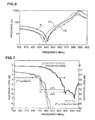
- Fig. 6 shows impedance characteristics of the first to third parallel arm resonators P1 to P3 in the band rejection filter 1 according to the first example.
- a solid line denoted by a reference symbol P1 represents the impedance characteristic of the first parallel arm resonator P1.
- a dashed line denoted by a reference symbol P2 represents the impedance characteristic of the second parallel arm resonator P2.
- a dotted line denoted by a reference symbol P3 represents the impedance or the third parallel arm resonator P3.
- the resonant frequency of the third parallel arm resonator P3 is the lowest resonant frequency.
- the filter characteristic in the transition band is determined by the third parallel arm resonator P3.
- Fig. 7 shows insertion losses of the band rejection filter 1 according to the first example and the band rejection filter according to the first comparative example.
- Solid lines in a graph shown in Fig. 7 represents insertion losses of the band rejection filter 1 according to the first example, and dashed lines in the graph shown in Fig. 7 represents insertion losses of the band rejection filter according to the first comparative example.
- the band rejection filter 1 of the first example is mounted on cellular phones having a function of receiving broadcasting service for mobile devices for digital terrestrial television broadcasting in Japan. Therefore, the band rejection filter 1 of the first example is disposed between an antenna (not shown) and a TV tuner (not shown) for receiving the broadcasting service for mobile devices in such a cellular phone.
- a second passband of the band rejection filter 1 of the first example corresponds to a range from approximately 470 MHz to approximately 780 MHz. Furthermore, since a band for transmission signals of cellular phones is included in a range from approximately 800 MHz to approximately 900 MHz, a second attenuation band of the band rejection filter 1 according to the first example corresponds to a range from approximately 830 MHz to approximately 845 MHz.
- the band rejection filter 1 of the first example has a function of allowing the broadcasting signals of the broadcasting service for mobile devices to pass toward the TV tuner for receiving the broadcasting service for mobile devices and removing the transmission signals of the cellular phones.
- the band rejection filter 1 of the first example has higher sharpness of the filter characteristic in the transition band which is located on a lower side relative to the second attenuation band than the band rejection of the first comparative example.
- a difference ( ⁇ F) between a frequency corresponding to an insertion loss of 3 dB on a higher side relative to the second passband and a frequency corresponding to an insertion loss of 50 dB on a lower side relative to the second attenuation band 38.1 MHz is obtained in the first comparative example (AF2) whereas 36.3 MHz is obtained in the first example ( ⁇ F1).
- the frequency difference ( ⁇ F1) of the first example is smaller than the frequency difference ( ⁇ F2) of the first comparative example by 1.8 MHz. Consequently, it is recognized that the sharpness of the filter characteristic in the transition band which is located on the lower side relative to the second attenuation band can be enhanced by making the propagation angle ( ⁇ ) of the third parallel arm resonator P3 which has the lowest resonant frequency larger than the propagation angle ( ⁇ ) of the first and second parallel arm resonators P1 and P2.
- the band for transmission signals of cellular phones ins included in the vicinity of approximately 1.5 GHz, approximately 1.7 GHz, and approximately 2.0 GHz. Since such a band for transmission signals of cellular phones ins included in the first attenuation band of the band rejection filter 1 of the first example, the band rejection filter 1 the transmission signals of cellular phones. Therefore, the transmission signals of cellular phones are prevented from being transmitted to the TV tuner for receiving the broadcasting service for mobile devices which is disposed in a later stage of the band rejection filter 1.
- the band rejection filter 1 of the first example can remove not only the transmission signals of cellular phones in the vicinity of a range from approximately 800 MHz to approximately 900 MHz but also transmission signals of cellular phones in the vicinity of approximately 1.5 GHz, approximately 1.7 GHz, and approximately 2.0 GHz. Consequently, the band rejection filter 1 of the first example can reliably prevent interference between the transmission signals of cellular phones and the broadcasting signals of the broadcasting service for mobile devices.
- the present invention is not limited to this configuration.
- the propagation angles ( ⁇ ) of the first and second parallel arm resonators P1 and P2 may be different from each other, or one of the propagation angles ( ⁇ ) of the first and second parallel arm resonators P1 and P2 may be the same as the propagation angle ( ⁇ ) of the third parallel arm resonator P3.
- an electromechanical coupling coefficient (k 2 ) of at least one of the parallel arm resonators which contributes to formation of a transition band is smaller than electromechanical coupling coefficients (k 2 ) of the others of the parallel arm resonators by setting the propagation angle ( ⁇ ) of the parallel arm resonator which contributes to the formation of the transition band to be larger than the propagation angles ( ⁇ ) of the others of the parallel arm resonators. Accordingly, with the first embodiment, sharpness of an impedance characteristic of the parallel arm resonator which has the lowest resonant frequency and which contributes to the formation of the transition band is enhanced, and sharpness of a filter characteristic in the transition band is enhanced.
- an electromechanical coupling coefficient (k 2 ) of at least one of the parallel arm resonators which contributes to formation of a transition band is smaller than an electromechanical coupling coefficient (k 2 ) of at least one of the parallel arm resonators by setting the propagation angle ( ⁇ ) of the parallel arm resonator which contributes to the formation of the transition band to be larger than the propagation angle ( ⁇ ) of at least one of the parallel arm resonators. Accordingly, as with the first embodiment, sharpness of an impedance characteristic of the parallel arm resonator which has the lowest resonant frequency and which contributes to the formation of the transition band is enhanced, and sharpness of a filter characteristic in the transition band is enhanced.
- Fig. 8 is a circuit diagram illustrating a band rejection filter according to a second embodiment.
- the band rejection filter of the second embodiment includes a ladder circuit including a series arm 10 which connects an input terminal 6 and an output terminal 7 to each other, and first and second parallel arms 13a and 13b which are connected between the series arm 10 and the ground potential.
- first to third inductance elements 40 to 42 and first and second series arm resonators S1 and S2 are arranged in the series arm 10.
- the first and second series arm resonators S1 and S2 are connected to each other in series in the series arm 10.
- the first inductance element 40 is connected between the input terminal 6 and the first series arm resonator S1.
- the second inductance element 41 is connected between the first and second series arm resonators S1 and S2.
- the third inductance element 42 is connected between the second series arm resonator S2 and the output terminal 7.
- the first and second parallel arms 13a and 13b are connected between the series arm 10 and the ground potential.
- the first parallel arm 13a is connected between the ground potential and a point of connection between the first series arm resonator S1 and the second inductance element 41.
- the second parallel arm 13b is connected between the ground potential and a point of connection between the second inductance element 41 and the second series arm resonator S2.
- a first parallel arm resonator P1 is disposed in a first parallel arm resonator P1 in disposed.
- a second parallel arm resonator P2 is disposed in a second parallel arm 13b.
- the ladder circuit is configured by the first to third inductance elements 40 to 42 and the first and second series arm resonators S1 and S2 which are arranged in the series arm 10 and the first and second parallel arm resonators P1 and P2 which are disposed in the first and second parallel arms 13a and 13b, respectively.
- the first and second series arm resonators S1 and S2 and the first and second parallel arm resonators P1 and P2 are integrally formed as a single elastic wave element.
- the band rejection filter of the second embodiment includes first attenuation bands in which an insertion loss is large.
- the first attenuation bands are respectively formed on a lower side and a higher side.
- the lower first attenuation band is mainly formed by capacitances of the first and second series arm resonators S1 and S2.
- the higher first attenuation band is mainly formed by inductances of the first to third inductance elements 40 to 42 and capacitances of the first and second parallel arm resonators P1 and P2.
- the band rejection filter of the second embodiment has a first passband which is located between the lower first attenuation band and the higher first attenuation band and in which an insertion loss is small.
- the first passband is mainly formed by the inductances of the first to third inductance elements 40 to 42.
- the band rejection filter of the second embodiment has a second attenuation band which is included in the first passband and in which an insertion loss is large.
- the second attenuation band is mainly formed by attenuation poles generated due to antiresonances of the first and second series arm resonators S1 and S2 and attenuation poles generated due to resonances of the first and second parallel arm resonators P1 and P2.
- the band rejection filter of the second embodiment has a second passband which is included in the first passband, which is located on a lower side relative to the second attenuation band, and in which an insertion loss is small.
- the second passband is mainly formed by the inductances of the first to third inductance elements 40 to 42.
- the band rejection filter of the second embodiment has a transition band between the second attenuation band and the second passband.
- a propagation angle ( ⁇ ) of at least one of the elastic wave resonators is larger than propagation angles ( ⁇ ) of the others of the elastic wave resonators, Specifically, among the first and second series arm resonators S1 and S2 and the first and second parallel arm resonators P1 and P2, the propagation angle ( ⁇ ) of at least one of the elastic wave resonators which contributes to formation of the transition band is larger than the propagation angles ( ⁇ ) of the others of the elastic wave resonators, Accordingly, an electromechanical coupling coefficient (k 2 ) of at least one of the elastic wave resonators which contributes to the formation of the transition band is smaller than electromechanical coupling coefficients (k 2 ) of the others of the elastic wave resonators.
- the electromechanical coupling coefficient (k 2 ) of at least one of the elastic wave resonators which contributes to the formation of the transition band is smaller than the electromechanical coupling coefficients (k 2 ) of the others of the elastic wave resonators, and accordingly, sharpness of a filter characteristic at ends of the passbands can be enhanced while an attenuation amount is ensured. Furthermore, small insertion losses in the passbands are attained.
- a propagation angle ( ⁇ ) of one of the elastic wave resonators which has the lowest frequency among the antiresonant frequencies of the first and second series arm resonators S1 and S2 and the resonant frequencies of the first and second parallel arm resonators P1 and P2 is larger than propagation angles ( ⁇ ) of the others of the elastic wave resonators. Accordingly, an electromechanical coupling coefficient (k 2 ) of the elastic wave resonator having the lowest frequency is smaller than electromechanical coupling coefficients of the other elastic wave resonators. Therefore, the sharpness of the filter characteristic in the transition band which is located on the lower side relative to the second attenuation band is enhanced.
- an elastic wave resonator having the lowest frequency among the antiresonant frequencies of the first and second series arm resonators S1 and S2 and the resonant frequencies of the first and second parallel arm resonators P1 and P2 contributes to the formation of the transition band.
- the antiresonant frequency of the first series arm resonator S1 is the lowest frequency. Accordingly, the first series arm resonator S1 contributes to the formation of the transition band which is located on the lower side relative to the second attenuation band.
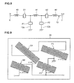
- Fig. 9 is a plan view schematically illustrating the elastic wave element according to the second embodiment.
- the electromechanical coupling coefficient (k 2 ) of the first series arm resonator S1 is smaller than the electromechanical coupling coefficients (k 2 ) of the second series arm resonator S2 and the first and second parallel arm resonators P1 and P2. Consequently, the sharpness of the impedance characteristic of the first series arm resonator S1 is enhanced, and high sharpness of the filter characteristic in the transition band located on the lower side relative to the second attenuation band is attained.
- the propagation angle ( ⁇ ) of the first series arm resonator S1 which contributes to the formation of the transition band is equal to or smaller than 45° and is larger than the propagation angles ( ⁇ ) of the other elastic wave resonators, that is, the second series arm resonator S2 and the first and second parallel arm resonators P1 and P2. Therefore, a TCF of the filter characteristic in the transition band is small. Accordingly, when the band rejection filter of the second embodiment is used, a large fabrication tolerance regarding frequencies is obtained, and a high fabrication yield rate is realized.
- the number of inductance elements and serial arm resonators which are arranged in the series arm and the number of parallel arm resonators which are disposed in the parallel arms are not restricted.
- the number of parallel arm resonators disposed in the parallel arms and the number of series arm resonators disposed in the series arm may be the same as each other or may be different from each other.
- a plurality of parallel arms may be connected and inductance elements may be disposed in the plurality of parallel arms.
- a band rejection filter according to a second example corresponding to the second embodiment is fabricated by a method the same as the method for fabricating the band rejection filter of the first example. Note that, in the second example, detailed configurations of first and second series arm resonators S1 and S2 and first and second parallel arm resonators P1 and P2 are as shown in Table 2 below.
- a band rejection filter according to a second comparative example is fabricated similarly to the second example except that all propagation angles ( ⁇ ) of first and second series arm resonators S1 and S2 and first to second parallel arm resonators P1 and P2 of the second comparative example are set to 10°.
- Impedance characteristics of the first and second series arm resonators S1 and S2 and the first to second parallel arm resonators P1 and P2 of the band rejection filter according to the second example are individually measured, and an insertion loss of the band rejection filter according to the second example and an insertion loss of the band rejection filter according to the second comparative example are measured.
- Fig. 10 shows impedance characteristics of the first and second parallel arm resonators P1 and P2 and the first and second series arm resonators S1 and S2 in the band rejection filter according to the second example.
- a solid line denoted by a reference symbol S1 the impedance characteristic of the first series arm resonator S1.
- a chain double-dashed line denoted by a reference symbol S2 represents the impedance characteristic of the second series arm resonator S2.
- a dotted line denoted by a reference symbol P1 represents the impedance characteristic of the second parallel arm resonator P1.
- a dashed line denoted by a reference symbol P2 represents the impedance characteristic of the second parallel arm resonator P2.
- the antiresonant frequency of the first series arm resonator S1 is the lowest frequency, and the following inequality is satisfied: (the antiresonant frequency of the first series arm resonator S1) ⁇ (the resonant frequency of the first parallel arm resonator P1) ⁇ (the resonant frequency of the second parallel arm resonator P2) ⁇ (the antiresonant frequency of the second series arm resonator S2). Consequently, in the band rejection filter of the second example, the filter characteristic in the transition band is determined by the first series arm resonator S1.
- Fig. 11 shows the insertion loss of the band rejection filter according to the second example and the insertion loss of the band rejection filter according to the second comparative example.
- Solid lines in a graph shown in Fig. 11 represent insertion losses of the band rejection filter of the second example
- dashed lines in the graph shown in Fig. 11 represent insertion losses of the band rejection filter of the second comparative example.
- the band rejection filter of the second example is mounted on cellular phones having a function of receiving broadcasting service for mobile devices for digital terrestrial television broadcasting in Japan. Since a band for broadcasting signals of the broadcasting service for mobile devices in Japan corresponds to a UHF band (470 to 770 MHz), a second passband of the band rejection filter of the second example corresponds to a range from approximately 470 MHz to approximately 800 MHz. Furthermore, since a band for transmission signals of cellular phones is included in a range from approximately 800 MHz to approximately 900 MHz, a second attenuation band of the band rejection filter according to the second example corresponds to a range from approximately 898 MHz to approximately 925 MHz.
- the band rejection filter of the second example has a function of allowing the broadcasting signals of the broadcasting service for mobile devices to pass toward the TV tuner for receiving the broadcasting service for mobile devices and removing the transmission signals of the cellular phones.
- the band rejection filter of the second example has higher sharpness of the filter characteristic in the transition band which is located on the lower side relative to the second attenuation band than the band rejection filter of the second comparative example.
- ⁇ F a difference between a frequency corresponding to an insertion loss of 3 dB on a higher side relative to the second passband and a frequency corresponding to an insertion loss of 50 dB on a lower side relative to the second attenuation band
- 66.7 MHz is obtained in the second comparative example ( ⁇ F4) whereas 63.6 MHz is obtained in the second example ( ⁇ F3).
- the frequency difference ( ⁇ F3) of the second example is smaller than the frequency difference ( ⁇ F4) of the second comparative example by 3.1 MHz. Consequently, it is recognized that the sharpness of the filter characteristic in the transition band which is located on the lower side relative to the second attenuation band can be enhanced by making the propagation angle ( ⁇ ) of one of the elastic wave resonators, that is, the first and second series arm resonators S1 and S2 and the first and second parallel arm resonators P1 and P2, which has the lowest frequency among the antiresonant frequencies of the first and second series arm resonators S1 and S2 and the resonant frequencies of the first to second parallel arm resonators P1 and P2, larger than the propagation angles ( ⁇ ) of the others of the elastic wave resonators.
- the band rejection filter of the second example removes the transmission signals of cellular phones. Therefore, the transmission signals of cellular phones are prevented from being transmitted to the TV tuner for receiving the broadcasting service for mobile devices which is disposed in a later stage of the band rejection filter.
- the band rejection filter of the second example can remove not only the transmission signals of cellular phones in the vicinity of a range from approximately 800 MHz to approximately 900 MHz but also transmission signals of cellular phones in the vicinity of approximately 1.5 GHz, approximately 1.7 GHz, and approximately 2.0 GHz. Consequently, the band rejection filter of the second example can reliably prevent interference between the transmission signals of cellular phones and the broadcasting signals of the broadcasting service for mobile devices.
- the present invention is not limited to this configuration.
- the propagation angles ( ⁇ ) of the second series arm resonator S2 and the first and second parallel arm resonators P1 and P2 may be different from one another, or any one of the propagation angles ( ⁇ ) of the second series arm resonator S2 and the first and second parallel arm resonators P1 and P2 may be the same as the propagation angle ( ⁇ ) of the first series arm resonator S1.
- an electromechanical coupling coefficient (k 2 ) of one of the elastic wave resonators which has the lowest frequency and which contributes to the formation of the transition band is smaller than electromechanical coupling coefficients (k 2 ) of the others of the elastic wave resonators by setting the propagation angle ( ⁇ ) of one of the elastic wave resonators which has the lowest frequency among the antiresonant frequencies of the first and second series arm resonators S1 and S2 and the re
- an electromechanical coupling coefficient (k 2 ) of one of the elastic wave resonators which has the lowest frequency and which contributes to the formation of the transition band is smaller than any one of electromechanical coupling coefficients (k 2 ) of the others of the elastic wave resonators by setting the propagation angle ( ⁇ ) of one of the elastic wave resonators which has the lowest frequency and which contributes to the formation of the transition band to be larger than any one of the propagation angles ( ⁇ ) of the others of the elastic wave resonators.
- the sharpness of the impedance characteristic of the elastic wave resonator which has the lowest frequency out of the anti-resonant frequencies of the series arm resonators and the resonant frequencies of the parallel arm resonators and which contributes to the formation of the transition band is enhanced, and the sharpness of the filter characteristic in the transition band is enhanced.
- Fig. 12 is a plan view schematically illustrating an elastic wave element according to a third embodiment.
- the band rejection filter according to the third embodiment is configured similarly to the band rejection filter according to the second embodiment shown in Fig. 8 except for propagation angles ( ⁇ ) of first and second series arm resonators S1 and S2 and first and second parallel arm resonators P1 and P2.
- the band rejection filter according to the third embodiment has first attenuation bands in which an insertion loss is large.
- the first attenuation bands are respectively formed on a lower side and a higher side.
- the lower first attenuation band is mainly formed by capacitances of the first and second series arm resonators S1 and S2.
- the higher first attenuation band is mainly formed by inductances of first to third inductance elements 40 to 42 and capacitances of the first and second parallel arm resonators P1 and P2.
- the band rejection filter of the third embodiment has a first passband which is located between the lower first attenuation band and the higher first attenuation band and in which an insertion loss is small.
- the first passband is mainly formed by the inductances of the first to third inductance elements 40 to 42.
- the band rejection filter of the third embodiment has a second attenuation band which is included in the first passband and in which an insertion loss is large.
- the second attenuation band is mainly formed by attenuation poles generated due to antiresonances of the first and second series arm resonators S1 and S2 and attenuation poles generated due to resonances of the first and second parallel arm resonators P1 and P2.
- the band rejection filter of the third embodiment has a second passband which is included in the first passband, which is located on a lower side relative to the second attenuation band, and in which an insertion loss is small.
- the second passband is mainly formed by the inductances of the first to third inductance elements 40 to 42.
- the band rejection filter of the third embodiment has a lower transition band between the second attenuation band and the second passband and a higher transition band on a higher side relative to the second attenuation band.
- the propagation angles ( ⁇ ) of the first and second series arm S1 and S2 are equal to or smaller than 45° and are larger than the propagation angles ( ⁇ ) of the first and second parallel arm resonators P1 and P2. Therefore, a TCF of the filter characteristic in the lower transition band between the second passband and the second attenuation band is small. Accordingly, also when the band rejection filter of this embodiment is used, a large fabrication tolerance regarding frequencies is obtained, and a high fabrication yield rate is realized.
- a band rejection filter according to a third example corresponding to the third embodiment is fabricated by a method the same as the method for fabricating the band rejection filter of the first example. Note that, in the third example, detailed configurations of first and second series arm resonators S1 and S2 and first and second parallel arm resonators P1 and P2 are as shown in Table 3 below.
- a band rejection filter according to a third comparative example is fabricated similarly to the third example except that all propagation angles ( ⁇ ) of first and second series arm resonators S1 and S2 and first to second parallel arm resonators P1 and P2 of the third comparative example are set to 10°.
- impedance characteristics resonant frequencies and antiresonant frequencies
- impedance characteristics of the first and second series arm resonators S1 and S2 and the first to second parallel arm resonators P1 and P2 of the band rejection filter according to the third example are individually measured.
- an elastic wave resonator having the lowest frequency among the antiresonant frequencies of the first and second series arm resonators S1 and S2 and the resonant frequencies of the first and second parallel arm resonators P1 and P2 contributes to formation of a lower transition band located between a second passband and a second attenuation band.
- Sharpness of a filter characteristic in the lower transition band located between the second passband and the second attenuation band is determined by frequency characteristics of the series arm resonators, specifically, by the resonant frequencies and the antiresonant frequencies of the series arm resonators.
- Fig. 13 shows impedance characteristics of the first and second parallel arm resonators P1 and P2 and the first and second series arm resonators S1 and S2 in the band rejection filter according to the third example.
- a solid line denoted by a reference symbol S1 represents the impedance characteristic of the first series arm resonator S1.
- a chain double-dashed line denoted by a reference symbol S2 represents the impedance characteristic of the second series arm resonator S2.
- a dotted line denoted by a reference symbol P1 represents the impedance characteristic of the second parallel arm resonator P1.
- a dashed line denoted by a reference symbol P2 represents the impedance characteristic of the third parallel arm resonator P2.
- the antiresonant frequency of the first series arm resonator S1 is the lowest frequency. Therefore, when the antiresonant frequency of the first series arm resonator S1 is compared with the antiresonant frequency of the second series arm resonator S2, the antiresonant frequency of the first series arm resonator S1 is lower.
- the frequency characteristic of the first series arm resonator S1 contributes the most to the filter characteristic in the lower transition band located between the second passband and the second attenuation band
- the frequency characteristic of the second series arm resonators S2 contributes the second most to the filter characteristic in the lower transition band.
- the band rejection filter of the third example is mounted on cellular phones having a function of receiving broadcasting service for mobile devices of digital terrestrial television broadcasting.
- the second passband of the band rejection filter of the third example corresponds to a range from approximately 470 MHz to approximately 760 MHz.
- the second attenuation band of the band rejection filter of the third example corresponds to a range from approximately 820 MHz to approximately 850 MHz.
- the band rejection filter of the third example has a function of allowing broadcasting signals of the broadcasting service for mobile devices to pass toward the TV tuner for receiving the broadcasting service for mobile devices and removing the transmission signals of the cellular phones.
- the band rejection filter of the third example has higher sharpness of the filter characteristic in the lower transition band which is located between the second passband and the second attenuation band than the band rejection filter of the third comparative example.
- ⁇ F a difference between a frequency corresponding to an insertion loss of 2 dB on a higher side relative to the second passband and a frequency corresponding to an insertion loss of 50 dB on a lower side relative to the second attenuation band
- 42.7 MHz is obtained in the third comparative example ( ⁇ F6) whereas 37.6 MHz is obtained in the third example ( ⁇ F5).
- the frequency difference ( ⁇ F5) of the third example is smaller than the frequency difference ( ⁇ F6) of the third comparative example by 5.1 MHz. Consequently, it is recognized that the sharpness of the filter characteristic in the lower transition band which is located between the second passband and the second attenuation band can be enhanced by making the propagation angles ( ⁇ ) of the first and second series arm resonators S1 and S2 larger than the propagation angles ( ⁇ ) of the first to second parallel arm resonators P1 and P2.
- Fig. 15 is a graph illustrating insertion losses of the band rejection filter according to the third embodiment, the band rejection filter according to the third comparative example, and a band rejection filter in which only the propagation angles ( ⁇ ) of the series arm resonators of the third example are changed.
- dashed lines in a graph shown in Fig. 15 represent insertion losses of the band rejection filter in which the first and second series arm resonators S1 and S2 have propagation angles ( ⁇ ) of 10° which are the same as those of the first and second parallel arm resonators P1 and P2.
- solid lines in the graph shown in Fig. 15 represent insertion of the band rejection filter according to the third example.
- Chain double-dashed lines in the graph shown in Fig. 15 represent insertion losses of the band rejection filter according to the third comparative example.
- Fig. 16 is a graph illustrating impedance characteristics of elastic wave resonators having propagation angles ( ⁇ ) of 30° and 0°
- a solid line in a graph shown in Fig. 16 represents the impedance characteristic of the elastic wave resonator having the propagation angle ( ⁇ ) of 30°.
- a dashed line in the graph represents the impedance characteristic of the elastic wave resonator having the propagation angle ( ⁇ ) of 0°.
- a large propagation angle ( ⁇ ) of an elastic resonator is set so that a small electromechanical coupling coefficient (k 2 ) of the elastic wave resonator is obtained, a resonant frequency and an antiresonant frequency of the elastic wave resonator are close to each other. Therefore, sharpness of an impedance characteristic is enhanced. Accordingly, the sharpness of the filter characteristic in the transition band can be enhanced by making the propagation angles ( ⁇ ) of the first and second series arm resonators S1 and S2 which contribute the formation of the transition band larger than the propagation angles ( ⁇ ) of the first and second parallel arm resonators P1 and P2.
- the band rejection filter of the third example removes the transmission signals of cellular phones. Therefore, the transmission signals of cellular phones are prevented from being transmitted to the TV tuner for receiving broadcasting service for mobile devices which is disposed in a later stage of the band rejection filter.
- the band rejection filter of the third example can remove not only the transmission signals of cellular phones in the vicinity of a range from approximately 800 MHz to approximately 900 MHz but also the transmission signals of cellular phones in the vicinity of approximately 1.5 GHz, approximately 1.7 GHz, and approximately 2.0 GHz. Consequently, the band rejection filter of the third example can reliably prevent interference between the transmission signals of cellular phones and the broadcasting signals of the broadcasting service for mobile devices.
- the propagation angles ( ⁇ ) of the first and second parallel arm resonators P1 and P2 are the same as each other.
- the present invention is not limited to such a configuration.
- the propagation angles ( ⁇ ) of the first and second parallel arm resonators P1 and P2 may be different from each other, or one of the propagation angles ( ⁇ ) of the first and second parallel arm resonators P1 and P2 may be the same as the propagation angles ( ⁇ ) of the first and second series arm resonators S1 and S2.
- Fig. 17 is a circuit diagram illustrating a band rejection filter according to a fourth embodiment.
- the band rejection filter according to the fourth embodiment includes a ladder circuit having a series arm 10 which connects an input terminal 6 and an output terminal 7 to each other and first and second parallel arms 13a and 13b which are connected between the series arm 10 and the ground potential.
- first to third series arm resonators S1 to S3 are arranged in the series arm 10. Between the series arm 10 and the ground potential, the first and second parallel arms 13a and 13b are connected. Specifically, the first parallel arm 13a is connected between the ground potential and a point of connection between the first series arm resonator S1 and the second series arm resonator S2 in the series arm 10. In the first parallel arm 13a, a first inductance element 50 is disposed. On the other hand, the second parallel arm 13b is connected between the ground potential and a point of connection between the second series arm resonator S2 and the third series arm resonator S3. In the second parallel arm 13b, a second inductance element 51 is disposed.
- the ladder circuit is configured by the first to third series arm resonators S1 to S3 arranged in the series arm 10 and the first and second inductance elements 50 and 51 disposed in the first and second parallel arms 13a and 13b, respectively.
- the first and second series arm resonators S1 and S2 and the first and second parallel arm resonators P1 and P2 are integrally formed as a single elastic wave element.
- the band rejection filter of the fourth embodiment has a first attenuation band in which an insertion loss is large.
- the first attenuation band is mainly formed by inductances of the first and second inductance elements 50 and 51 and capacitances of the first to third series arm resonators S1 to S3.
- the band rejection filter according to the fourth embodiment has a first passband which is located on a higher side relative to the first attenuation band and in which in insertion loss is small.
- the first passband is mainly formed by the inductances of the first and second inductance elements 50 and 51.
- the band rejection filter according to the fourth embodiment has a second attenuation band which is included in the first passband and in which an insertion loss is large.
- the second attenuation band is mainly formed by attenuation poles generated due to antiresonances of the first to third series arm resonators S1 to S3.
- the band rejection filter according to the fourth embodiment has a second passband which is included in the first passband, which is located on a lower side relative to the second attenuation band, and in which in insertion loss is small.
- the second passband is mainly formed by the inductances of the first and second inductance elements 50 and 51.
- the band rejection filter according to the fourth embodiment has a lower transition band between the second attenuation band and the second passband and a higher transition band on a higher side relative to the second attenuation band.
- a propagation angle ( ⁇ ) of at least one of the first to third series arm resonators S1 to S3 is larger than propagation angles ( ⁇ ) of the others of the first to third series arm resonators S1 to S3.
- the propagation angle ( ⁇ ) of at least one of the first to third series arm resonators S1 to S3 which contributes to formation of the transition bands is larger than the propagation angles ( ⁇ ) of the others of the first to third series arm resonators S1 to S3.
- an electromechanical coupling coefficient (k 2 ) of at least one of the series arm resonators which contributes to the formation of the transition bands is smaller than electromechanical coupling coefficients (k 2 ) of the others of the serial arm resonators.
- the propagation angle ( ⁇ ) of at least one of the first to third series arm resonators S1 to S3 which contributes to the formation of the transition bands is larger than the propagation angles ( ⁇ ) of the others of the first to third series arm resonators S1 to S3
- sharpness of a filter characteristic at ends of the passbands can be enhanced while an attenuation amount is ensured by making the electromechanical coupling coefficient (k 2 ) of at least one of the series arm resonators which contributes to the formation of the transition bands smaller than the electromechanical coupling coefficients (k 2 ) of the others of the serial arm resonators.
- small insertion losses in the passbands can be attained.
- the series arm resonator having the highest antiresonant frequency contributes to the formation of the transition band.
- the propagation angle ( ⁇ ) of at least one of the first to third series arm resonators S1 to S3 which has the highest antiresonant frequencies among the antiresonant frequencies of the first to third series arm resonators S1 to S3 is larger than propagation angles ( ⁇ ) of the others of the first to third series arm resonators, and accordingly, the electromechanical coupling coefficient (k 2 ) of at least one of the series arm resonators which has the highest antiresonant frequency is smaller than the electromechanical coupling coefficients (k 2 ) of the others of the serial arm resonators. Accordingly, the high sharpness of the filter characteristic in the higher transition band which is located on the higher side of the second attenuation band is enhanced.
- the third series arm resonator S3 has the highest antiresonant frequency among the antiresonant frequencies of the first to third series arm resonators S1 to S3. Therefore, the third series arm resonator S3 contributes to the formation of the higher transition band which is located on the higher side of the attenuation band.
- Fig. 18 is a plan view schematically illustrating the elastic wave element according to the fourth embodiment.
- an electromechanical coupling coefficient (k 2 ) of the third series arm resonator S3 is smaller than electromechanical coupling coefficients (k 2 ) of the first and second series arm resonators S1 and S2.
- the propagation angle ( ⁇ ) of the third series arm resonator S3 which contributes to the formation of the higher transition band which is located on the higher side relative to the second attenuation band is equal to or smaller than 45° and is larger than the propagation angles ( ⁇ ) of the first and second series arm resonators S1 and S2. Therefore, a TCF of the filter characteristic in the higher transition band which is located on the higher side relative to the second attenuation band is small. Accordingly, when the band rejection filter of this embodiment is used, a large fabrication tolerance regarding frequencies is obtained, and a high fabrication yield rate is realized.
- a band rejection filter according to a fourth example corresponding to the fourth embodiment is fabricated by a method the same as the method for fabricating the band rejection filter of the first example. Note that, in the fourth example, detailed configurations of first to third series arm resonators S1 to S3 and are as shown in Table 4 below.
- a band rejection filter according to a fourth comparative example is fabricated similarly to the fourth example except that all propagation angles ( ⁇ ) of first to third series arm resonators S1 to S3 of the fourth comparative example are set to 10°.
- Impedance characteristics of the first to third series arm resonators S1 to S3 of the band rejection filter according to the fourth example are individually measured, and insertion losses of the band rejection filter according to the fourth example and the band rejection filter according to the fourth comparative example are measured.
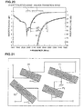
- Fig. 19 is a graph illustrating impedance characteristics of the first to third series arm resonators S1 to S3 according to the fourth example.
- a solid line denoted by a reference symbol S1 represents the impedance characteristic of the first series arm resonator S1.
- a dashed line denoted by a reference symbol S2 represents the impedance characteristic of the second series arm resonator S2.
- a dotted line denoted by a reference symbol S3 represents the impedance characteristic of the third series arm resonator S3.
- Fig. 20 is a graph illustrating results of the measurement of the insertion losses oaf the band rejection filter according to the fourth example and the band rejection filter according to the fourth comparative example. Solid lines in a graph shown in Fig. 20 represent insertion losses of the band rejection filter of the fourth example, and dashed lines in the graph shown in Fig. 20 represent insertion losses of the band rejection filter of the fourth comparative example.
- the band rejection filter of the fourth example has higher sharpness of a filter characteristic in the higher transition band which is located on the higher side relative to the second attenuation band than the band rejection filter of the fourth comparative example, Specifically, as a difference ( ⁇ F) between a frequency corresponding to an insertion loss of 3 dB on a higher side relative to the second attenuation band included in the first passband and a frequency corresponding to an insertion loss of 40 dB on the higher side relative to the second attenuation band, 197.4 MHz is obtained in the fourth comparative example ( ⁇ F8) whereas 185.7 MHz is obtained in the fourth example ( ⁇ F7).
- the frequency difference ( ⁇ F7) of the fourth example is smaller than the frequency difference ( ⁇ F8) of the fourth comparative example by 11.7 MHz. Consequently, it is recognized that the sharpness of the filter characteristic in the higher transition band which is located on the higher side relative to the second attenuation band can be enhanced by making the propagation angle ( ⁇ ) of the third series arm resonator S3 which has the highest antiresonant frequency larger than the propagation angles ( ⁇ ) of the first and second series arm resonators S1 and S2.
- the present invention is not restricted by this configuration.
- the propagation angles ( ⁇ ) of the first and second series arm resonators S1 and S2 may be different from each other, and one of the propagation angles ( ⁇ ) of the first and second series arm resonators S1 and S2 may be the same as the propagation angle ( ⁇ ) of the third series arm resonator S3.
- an electromechanical coupling coefficient (k 2 ) of at least one of the series arm resonators which contributes to formation of a higher transition band is smaller than electromechanical coupling coefficients (k 2 ) of the others of the series arm resonators by setting the propagation angle ( ⁇ ) of the series arm resonator which contributes to the formation of the higher transition band to be larger than the propagation angles ( ⁇ ) of the other series arm resonators.
- the sharpness of the impedance characteristic of the series arm resonator has the highest antiresonant frequency and which contributes to the formation of the higher transition band is enhanced, and the sharpness of the filter characteristic in the transition band is enhanced.
- an electromechanical coupling coefficient (k 2 ) of at least one of the series arm resonators which has the highest antiresonant frequency and which contributes to the formation of the higher transition band is smaller than any one of electromechanical coupling coefficients (k 2 ) of the others of the series arm resonators by setting the propagation angle ( ⁇ ) of the series arm resonator which contributes to the formation of the higher transition band to be larger than any one of the propagation angles ( ⁇ ) of the others of the series arm resonators.
- the sharpness of the impedance characteristic of the series arm resonator which has the highest antiresonant frequency and which contributes to the formation of the transition band is enhanced, and the sharpness of the filter characteristic in the transition band is enhanced.
- Fig. 21 is a plan view schematically illustrating an elastic wave element according to a fifth embodiment.
- the band rejection filter according to the fifth embodiment is configured similar to the band rejection filter according to the second embodiment shown in Fig. 8 , one difference being propagation angles ( ⁇ ) of first and second series arm resonators S1 and S2 and first and second parallel arm resonators P1 and P2.
- the band rejection filter according to the fifth embodiment has first attenuation bands in which an insertion loss is large.
- the first attenuation bands are respectively formed on a lower side and a higher side.
- the lower first attenuation band is mainly formed by capacitances of the first and second series arm resonators S1 and S2.
- the higher first attenuation band is mainly formed by inductances of first to third inductance elements 40 to 42 and capacitances of the first and second parallel arm resonators P1 and P2.
- the band rejection filter of the fifth embodiment has a first passband which is located between the lower first attenuation band and the higher first attenuation band and in which an insertion loss is small,
- the first passband is mainly formed by the inductances of the first to third inductance elements 40 to 42.
- the band rejection filter of the fifth embodiment has a second attenuation band which is included in the first passband and in which an insertion loss is large.
- the second attenuation band is mainly formed by attenuation poles generated due to antiresonances of the first and second series arm resonators S1 and S2 and attenuation poles generated due to resonances of the first and second parallel arm resonators P1 and P2.
- the band rejection filter of the fifth embodiment has a second passband which is included in the first passband, which is located on a lower side relative to the second attenuation band, and in which an insertion loss is small.
- the second passband is mainly formed by the inductances of the first to third inductance elements 40 to 42.
- the band rejection filter of the fifth embodiment has a lower transition band between the second attenuation band and the second passband and a higher transition band on a higher side relative to the second attenuation band.
- a propagation angle ( ⁇ ) of at least one of the first and second series arm resonators S1 and S2 and the first and second parallel arm resonators P1 and P2 is larger than propagation angles ( ⁇ ) of the others of the elastic wave resonators.
- the propagation angle ( ⁇ ) of at least one of the first and second series arm resonators S1 and S2 and the first and second parallel arm resonators P1 and P2 which contributes to formation of the transition bands is larger than the propagation angles ( ⁇ ) of the others of the elastic wave resonators.
- an electromechanical coupling coefficient (k 2 ) of at least one of the series arm resonators which contributes to the formation of the transition bands is smaller than electromechanical coupling coefficients (k 2 ) of the others of the serial arm resonators.
- the propagation angle ( ⁇ ) of at least one of the first and second series arm resonators S1 and S2 and the first and second parallel arm resonators P1 and P2 which contributes to the formation of the transition band is larger than the propagation angles ( ⁇ ) of the others of the elastic wave resonators, sharpness of a filter characteristic at ends of the passbands can be enhanced while an attenuation amount is ensured by making the electromechanical coupling coefficient (k 2 ) of at least one of the elastic wave resonators which contributes to the formation of the transition bands smaller than the electromechanical coupling coefficients (k 2 ) of the others of the elastic wave resonators. Furthermore, small insertion losses in the passbands can be attained.
- the propagation angle ( ⁇ ) of at least one of the first and second series arm resonators S1 and S2 and the first and second parallel arm resonators P1 and P2 which has the highest frequency among the antiresonant frequencies of the first and second series arm resonators S1 and S2 and the resonant frequencies of first and second parallel arm resonators P1 and P2 is larger than the propagation angles ( ⁇ ) of the others of the elastic wave resonators, and accordingly, the electromechanical coupling coefficient (k 2 ) of at least one of the elastic wave resonators which has the highest frequency is smaller than the electromechanical coupling coefficients (k 2 ) of the others of the elastic wave resonators. Accordingly, high sharpness of a filter characteristic in the higher transition band which is located on the higher side relative to the second attenuation band is enhanced.
- the elastic wave resonator having the highest frequency selected from among the antiresonant frequencies of the first and second series arm resonators S1 and S2 and the resonant frequencies of the first and second parallel arm resonators P1 and P2 contributes to the formation of the higher transition band which is located on the higher side relative to the second attenuation band.
- the antiresonant frequency of the second series arm resonator S2 is the highest frequency. Therefore, the second series arm resonator S2 contributes to the formation of the higher transition band which is located on the higher side relative to the second attenuation band.
- sharpness of an impedance characteristic of the second series arm resonator S2 is enhanced, and high sharpness of a filter characteristic in the higher transition band which is located on the higher side relative to the second attenuation band is realized.
- the propagation angle ( ⁇ ) of the second series arm resonator S2 which contributes to the formation of the higher transition band which is located on the higher side relative to the second attenuation band is equal to or smaller than 45° and is larger than the propagation angles ( ⁇ ) of the other elastic wave resonators, that is, the first series arm resonator S1 and the first and second parallel arm resonators P1 and P2. Therefore, a TCF of the filter characteristic in the higher transition band which is located on the higher side relative to the second attenuation band is small. Accordingly, when the band rejection filter of this embodiment is used, a large fabrication tolerance regarding frequencies is obtained, and a high fabrication yield rate is realized.
- the number of inductance elements and the series arm resonators arranged in the series arm and the number of parallel arm resonators arranged in the parallel arms are not restricted.
- the number of parallel arm resonators disposed in the parallel arms and the number of series arm resonators arranged in the series arm may be the same as each other or may be different from each other.
- a plurality of parallel arms may be further connected and inductance elements may be disposed in the plurality of parallel arms.
- a band rejection filter according to a fifth example corresponding to the fifth embodiment is fabricated by a method the same as the method for fabricating the band rejection filter of the first example. Note that, in the fifth example, detailed configurations of first and second series arm resonators S1 and S2 and first and second parallel arm resonators P1 and P2 are as shown in Table 5 below,
- a band rejection filter according to a fifth comparative example is fabricated similarly to the fifth example except that all propagation angles ( ⁇ ) of first and second series arm resonators S1 and S2 and first to second parallel arm resonators P1 and P2 of the fifth comparative example are set to 20°.
- Impedance characteristics of the first and second series arm resonators S1 and S2 and the first to second parallel arm resonators P1 and P2 of the band rejection filter according to the fifth example are individually measured, and an insertion loss of the band rejection filter according to the fifth example and an insertion loss of the band rejection filter according to the fifth comparative example are measured.
- Fig. 22 shows impedance characteristics of the first and second series arm resonators S1 and S2 and the first and second parallel arm resonators P1 and P2 of the band rejection filter according to the fifth example.
- a solid line denoted by a reference symbol P1 represents the impedance characteristic of the first parallel arm resonator P1
- a chain double-dashed line denoted by a reference symbol P2 represents the impedance characteristic of the second parallel arm resonator P2.
- a dotted line denoted by a reference symbol S1 represents the impedance characteristic of the first series arm resonator S1.
- a dashed line denoted by a reference symbol S2 represents the impedance characteristic of second parallel arm resonators S2.
- the antiresonant frequency of the second series arm resonator S2 is the highest frequency, and the following inequality is satisfied: (the resonant frequency of the first parallel arm resonator P1) ⁇ (the resonant frequency of the second parallel arm resonator P2) ⁇ (the antiresonant frequency of the first series arm resonator S1) ⁇ (the antiresonant frequency of the second series arm resonator S2). Consequently, in the band rejection filter of the fifth example, a filter characteristic in a higher transition band which is located on a higher side relative to a second attenuation band is determined by the second series arm resonator S2.
- Fig. 23 shows results of the measurement of the insertion losses of the band rejection filter according to the fifth example and the band rejection filter according to a fifth comparative example. Note that solid lines in a graph shown in Fig. 23 represent insertion loss of the band rejection filter of the fifth example, and dashed lines in the graph shown in Fig. 23 represent insertion loss of the band rejection filter of the fifth comparative example.
- the band rejection filter of the fifth example has higher sharpness of the filter characteristic in the higher transition band which is located on the higher side relative to the second attenuation band than the band rejection filter of the fifth comparative example.
- a difference ( ⁇ F) between a frequency corresponding to an insertion loss of 6 dB on a higher side relative to the second attenuation band included in a first passband and a frequency corresponding to an insertion loss of 50 dB on a higher side relative to the second attenuation band 57.5 MHz is obtained in the fifth comparative example ( ⁇ F10) whereas 46.0 MHz is obtained in the fifth example ( ⁇ F9). That is, the frequency difference ( ⁇ F9) of the fifth example is smaller than the frequency difference ( ⁇ F10) of the fifth comparative example by 11.5 MHz.
- the sharpness of the filter characteristic in the higher transition band which is own the higher side relative to the second attenuation band can be enhanced by making the propagation angle ( ⁇ ) of one of the elastic wave resonators which has the highest resonant frequency among the antiresonant frequencies of the first and second series arm resonators S1 and S2 and the resonant frequencies of the first and second parallel arm resonators P1 and P2 larger than the propagation angles ( ⁇ ) of the others of the elastic wave resonators.
- the propagation angles ( ⁇ ) of the first series arm resonator S1 and the first and second parallel arm resonators P1 and P2 are the same as one another.
- the present invention is not restricted to this configuration.
- the propagation angles ( ⁇ ) of the first series arm resonator S1 and the first and second parallel arm resonators P1 and P2 may be different from one another, or one of the propagation angles ( ⁇ ) of the first series arm resonator S1 and the first and second parallel arm resonators P1 and P2 may be the same as the propagation angle ( ⁇ ) of the second series arm resonator S2.
- the electromechanical coupling coefficient (k 2 ) of the elastic wave resonator which has the highest frequency among the antiresonant frequencies of S1 and S2 and the resonant frequencies of P1 and P2 and which contributes to the formation of the transition band is smaller than the electromechanical coupling coefficients (k 2 ) of the other elastic wave resonators by setting the propagation angle ( ⁇ ) of the elastic wave resonator which has the highest frequency and which contributes
- the sharpness of the impedance characteristic of the elastic wave resonator which has the highest frequency among the antiresonant frequencies of S1 and S2 and the resonant frequencies of P1 and P2 and which contributes to the formation of the transition band is enhanced, and the sharpness of the filter characteristic in the higher transition band which is located on the higher side relative to the second attenuation band is enhanced.
- the electromechanical coupling coefficient (k 2 ) of the elastic wave resonator which has the highest frequency among the antiresonant frequencies of S1 and S2 and the resonant frequencies of P1 and P2 and which contributes to the formation of the transition band is smaller than any one of the electromechanical coupling coefficients (k 2 ) of the other elastic wave resonators by setting the propagation angle ( ⁇ ) of the elastic wave resonator
- the sharpness of the impedance characteristic of the elastic wave resonator which has the highest frequency among the antiresonant frequencies of S1 and S2 and the resonant frequencies of P1 and P2 and which contributes to the formation of the transition band is enhanced, and the sharpness of the filter characteristic in the higher transition band which is located on the higher side relative to the second attenuation band is enhanced.
- Fig. 24 is a plan view schematically illustrating an elastic wave element according to a sixth embodiment.
- the band rejection filter according to the sixth embodiment is configured similar to the band rejection filter according to the second embodiment shown in Fig. 8 , one difference being propagation angles ( ⁇ ) of first and second series arm resonators S1 and S2 and first and second parallel arm resonators P1 and P2.
- the band rejection filter according to the sixth embodiment has first attenuation bands in which an insertion loss is large.
- the first attenuation bands are respectively formed on a lower side and a higher side.
- the lower first attenuation band is mainly formed by capacitances of the first and second series arm resonators S1 and S2.
- the higher first attenuation band is mainly formed by inductances of first to third inductance elements 40 to 42 and capacitances of the first and second parallel arm resonators P1 and P2.
- the band rejection filter of the sixth embodiment has a first passband which is located between the lower first attenuation band and the higher first attenuation band and in which an insertion loss is small.
- the first passband is mainly formed by the inductances of the first to third inductance elements 40 to 42.
- the band rejection filter of the sixth embodiment has a second attenuation band which is included in the first passband and in which an insertion loss is large.
- the second attenuation band is mainly formed by attenuation poles generated due to antiresonances of the first and second series arm resonators S1 and S2 and attenuation poles generated due to resonances of the first and second parallel arm resonators P1 and P2.
- the band rejection filter of the sixth embodiment has a second passband which is included in the first passband, which is located on a lower side relative to the second attenuation band, and in which an insertion loss is small.
- the second passband is mainly formed by the inductances of the first to third inductance elements 40 to 42.
- the band rejection filter of the sixth embodiment has a lower transition band between the second attenuation band and the second passband and a higher transition band on a higher side relative to the second attenuation band.
- the propagation angles ( ⁇ ) of the first and second parallel arm resonators P1 and P2 are equal to or smaller than and are larger than the propagation angles ( ⁇ ) of the first and second series arm resonators S1 and S2. Therefore, a TCF of the filter characteristic in the higher transition band which is located on the higher side relative to the second attenuation band is small. Accordingly, also when the band rejection filter of this embodiment is used, a large fabrication tolerance regarding frequencies is obtained, and a high fabrication yield rate is realized.
- a band rejection filter according to a sixth example corresponding to the sixth embodiment is fabricated by a method the same as the method for fabricating the band rejection filter of the first example. Note that, in the sixth example, detailed configurations of first and second series arm resonators S1 and S2 and first and second parallel arm resonators P1 and P2 are as shown in Table 6 below.
- a band rejection filter according to a sixth comparative example is fabricated similarly to the sixth example except that all propagation angles ( ⁇ ) of first and second series arm resonators S1 and S2 and first to second parallel arm resonators P1 and P2 of the sixth comparative example are to 10°.
- impedance characteristics (resonant frequencies and antiresonant frequencies) of the first and second series arm resonators S1 and S2 and the first to second parallel arm resonators P1 and P2 of the band rejection filter according to the sixth example are individually measured.
- an elastic wave resonator having the highest frequency among antiresonant frequencies of the first and second series arm resonators S1 and S2 and resonant frequencies of the first and second parallel arm resonators P1 and P2 contributes to formation of a higher transition band located on a higher side relative to a second attenuation band.
- Sharpness of a filter characteristic in the higher transition band located on the higher side relative to the second attenuation band is determined by frequency characteristics of the parallel arm resonators, specifically, by the resonant frequencies and antiresonant frequencies of the parallel arm resonators.
- Fig. 25 shows impedance characteristics of the first and second series arm resonators S1 and S2 and the first and second parallel arm resonators P1 and P2 of the band rejection filter according to the sixth example.
- a solid line denoted by a reference symbol S1 the impedance characteristic of the first series arm resonator S1.
- a chain double-dashed line denoted by a reference symbol S2 represents the impedance characteristic of the second series arm resonator S2.
- a dotted line denoted by a reference symbol P1 represents the impedance characteristic of the second parallel arm resonator P1.
- a dashed line denoted by a reference symbol P2 represents the impedance characteristic of the third parallel arm resonator P2.
- the resonant frequency of the second parallel arm resonator P2 is the highest frequency. Therefore, when the resonant frequency of the first arm resonator P1 is compared with the resonant frequency of the second parallel arm resonator P2, the resonant frequency of the second parallel arm resonator P2 is higher.
- a frequency characteristic of the second parallel arm resonator P2 contributes the most to the filter characteristic in the higher transition band which is located on the higher side relative to the second attenuation band
- a frequency characteristic of the first parallel arm resonator P1 contributes the second most to the filter characteristic in the higher transition band.
- Fig. 27 is a graph obtained by enlarging a portion of a graph shown in Fig. 26 . Note that, in Figs. 26 and 27 , solid lines of the graph represent insertion losses of the band rejection filter of the sixth example, and dashed lines in the graph represent insertion loss of the band rejection filter of the sixth comparative example.
- the sharpness of the filter characteristic in the higher transition band which is located on the higher side relative to the second attenuation band of the band rejection filter according to the sixth example is higher than the sharpness of the filter characteristic in the higher transition band of the band rejection filter according to the sixth comparative example. Consequently, it is recognized that the sharpness of the filter characteristic in the higher transition band which is located on the higher side relative to the second attenuation band can be enhanced by making the propagation angles ( ⁇ ) of the first and second parallel arm resonators P1 and P2 larger than the propagation angles ( ⁇ ) of the first and second series arm resonators S1 any S2.
- Fig. 28 shows insertion losses of the band rejection filter according to the sixth example, the band rejection filter according to the sixth comparative example, and a band rejection filter in which only the propagation angles ( ⁇ ) of the parallel arm resonators of the sixth example are changed.
- dashed lines in a graph shown in Fig. 28 represent insertion losses of the band rejection filter in which the propagation angle ( ⁇ ) of the first parallel arm resonator P1 is 10° which is the same as those of the first and second series arm resonators S1 and S2.
- solid lines in the graph shown in Fig. 28 represent insertion losses of the band rejection filter according to the sixth example.
- Chain double-dashed lines in the graph shown in Fig. 28 represent insertion losses of the band rejection filter according to the sixth comparative example.
- frequency characteristics of the first and second parallel arm resonators P1 and P2 contribute the filter characteristic in the higher transition band located on the higher side relative to the second attenuation band. It is recognized that especially the sharpness of the filter characteristic in the higher transition band located on the higher side relative to the second attenuation band can be enhanced by making the propagation angles ( ⁇ ) of the first and second parallel arm resonators P1 and P2 larger than the propagation angles ( ⁇ ) of the first and second series arm resonators S1 and S2.
- ⁇ F a difference between a frequency corresponding to an insertion loss of 4 dB on a lower side relative to a higher passband and a frequency corresponding to an insertion loss of 40 dB on a higher side relative to the attenuation band
- 24.5 MHz is obtained in the sixth example ( ⁇ F11)
- 25.7 MHz is obtained in the sixth comparative example ( ⁇ F12)
- 25.0 MHz is obtained in the band rejection filter ( ⁇ F13) in which only the propagation angle ( ⁇ ) of the first parallel arm resonator P1 among the first and second parallel arm resonators P1 and P2 is set to 10° which is the same as those of the first and second series arm resonators S1 and S2.
- the reason that the sharpness of the filter characteristic in the higher transition band located on the higher side relative to the second attenuation band can be enhanced by making the propagation angles ( ⁇ ) of the first and second parallel arm resonators P1 and P2 larger than the propagation angles ( ⁇ ) of the first and second series arm resonators S1 and S2 is the same as the reason in the third example.
- the present invention is not limited to this configuration.
- the propagation angles ( ⁇ ) of the first and second series arm resonators S1 and S2 may be different from each other, or one of the propagation angles ( ⁇ ) of the first and second series arm resonators S1 and S2 may be the same as the propagation angles ( ⁇ ) of the first and second parallel arm resonators P1 and P2.
Landscapes
- Physics & Mathematics (AREA)
- Acoustics & Sound (AREA)
- Surface Acoustic Wave Elements And Circuit Networks Thereof (AREA)
- Piezo-Electric Or Mechanical Vibrators, Or Delay Or Filter Circuits (AREA)
Abstract
Description
- The present invention relates to band rejection filters, and particularly relates to a band rejection filter having a circuit configuration including a plurality of elastic wave resonators.
- In recent years, broadcasting service for mobile devices for digital terrestrial television broadcasting has been started in various countries including Japan, and practical use of such broadcasting service has been discussed in many countries. Under this circumstance, cellular phones having a function of receiving broadcasting service for mobile devices for digital terrestrial television broadcasting have been put into practical use. The cellular phones having the function of receiving broadcasting service for mobile devices for digital terrestrial television broadcasting include TV tuners used to receive the broadcasting service for mobile devices. In such a cellular phone, there arise problems in that, if a transmission signal of the cellular phone and a broadcasting signal of the broadcasting service for mobile devices interfere with each other, sensitivity for receiving the broadcasting service for mobile devices is deteriorated and a TV tuner for receiving the broadcasting service for mobile devices malfunctions.
- Therefore, such a cellular phone includes a band rejection filter used to prevent interference between the transmission signal of the cellular phone and the broadcasting signal of the broadcasting service for mobile devices by preventing the transmission signal of the cellular phone from being transmitted to the TV tuner used to receive the broadcasting service for mobile devices. The band rejection filter has a function of allowing the broadcasting signal of the broadcasting service for mobile devices to be transmitted to the TV tuner used to receive the broadcasting service for mobile devices and removing the transmission signal of the cellular phone, and is disposed between an antenna and the TV tuner used to receive the broadcasting service for mobile devices in the cellular phone.
- The band rejection filter should have a filter characteristic in which a passband which allows transmission signals of the broadcasting service for mobile devices to pass and an attenuation band which removes transmission signals of the cellular phone are included. In the broadcasting service for mobile devices for digital terrestrial television broadcasting in Japan, a band for broadcasting signals corresponds to a UHF band (470 to 770 MHz). On the other hand, a band for transmission signals for cellular phones corresponds to a band in the vicinity of 800 to 900 MHz. Therefore, band rejection filters included in the cellular phones having the function of receiving the broadcasting service for mobile devices in Japan include a passband corresponding to the UHF band (470 to 770 MHz) which is the band for the broadcasting signals and an attenuation band corresponding to a band in the vicinity of 800 to 900 MHz which is the band for the transmission signals for the cellular phones.
- In such a band rejection filter, in order to appropriately remove the transmission signals of the cellular phones, high sharpness of a filter characteristic is required between an end of the passband which allows the broadcasting signals of the broadcasting service for mobile devices to pass and the attenuation band which removes the transmission signals of the cellular phones.
- In general, as a filter having a passband and an attenuation band, a filter device having a ladder circuit configuration is known. For example,
Patent Document 1 andPatent Document 2 disclose various filters having respective ladder circuit configurations utilizing elastic waves.Fig. 29 shows afilter device 101 having a ladder circuit configuration disclosed inPatent Document 1. In thefilter device 101, a series arm which connects aninput terminal 102 to anoutput terminal 103 includes a plurality ofseries arm resonators 111 to 113 which are connected to one another in series. Furthermore, a plurality of parallel arms are disposed between the series arm and the ground potential. The plurality of parallel arms include respectiveparallel arm resonators 114 to 117. - In the
filter device 101, acapacitor 118 is connected to theparallel arm resonator 114 in parallel among the plurality ofparallel arm resonators 114 to 117. Therefore, an electromechanical coupling coefficient of theparallel arm resonator 114 is smaller than those of theparallel arm resonators 115 to 117. As a result, sharpness of the filter characteristic at ends of a passband is enhanced. - Furthermore,
Patent Document 1 discloses the following two methods as other methods for setting an electromechanical coupling coefficient different from other electromechanical coupling coefficient: -
- (1) a method for setting different standard film thicknesses (h/λ) to IDTs (Interdigital Transducers) included in resonators; and
- (2) a method for setting different duty ratios to the IDTs included in the resonators.
-
- [Patent Document 1] Japanese Patent No.
3827232 - [Patent Document 1] Japanese Unexamined Patent Application Publication No.
10-65490 - As described above, according to the
filter device 101 disclosed inPatent Document 1, the sharpness of the filter characteristic at the ends of the passband can be enhanced. However, there arises a problem in that, if the capacitor is connected to the parallel arm resonator in parallel as disclosed inPatent Document 1, an area in which the ladder circuit occupies is increased, and accordingly, cost for fabrication of the filter device is increased. - Furthermore, in a case where different electromechanical coupling coefficients are obtained by setting different standard film thicknesses (h/λ) to IDT included in resonators, different thin-film forming processes should be performed for different resonators. Accordingly, cost for fabrication of the filter device is increased.
- Moreover, an electromechanical coupling coefficient is mainly determined depending on a wafer member, and does not considerably depend on a duty ratio. Therefore, it is difficult to obtain different electromechanical coupling coefficients or resonators by setting different duty ratios to IDTs included in the resonators. Accordingly, it is difficult to efficiently improve sharpness of a filter characteristic at ends of a passband.
- As disclosed in
Patent Document 2, impedance characteristics of resonators can be controlled by controlling characteristics of inductance elements connected to parallel arm resonators in parallel. Accordingly, sharpness of a filter characteristic at ends of a passband can be enhanced. However, in a case where the characteristics of the inductance elements connected to the parallel arm resonators in parallel are controlled, since electromechanical coupling coefficients are not substantially changed, it is difficult to enhance the sharpness of the filter characteristic at the ends of the passband while an attenuation amount is maintained. - An object of the present invention is to provide an inexpensive compact band rejection filter which has high sharpness of a filter characteristic at ends of a passband and which attains a large attenuation amount.
- A band rejection filter according to the present invention includes a ladder circuit configuration including a series arm which connects an input terminal and an output terminal to each other, a parallel arm which is connected between the series arm and a ground potential, a plurality of elastic wave resonators which are disposed in at least one of the series arm and the parallel arm, and an inductance element which is disposed at least one of the series arm and the parallel arm, and has a first attenuation band, a first passband which is adjacent to the first attenuation band, a second attenuation band which is included in the first passband, and a transition band which is adjacent to the second attenuation band. At least one of the elastic wave resonators which contributes to formation of the transition band has a propagation angle larger than propagation angles of the others of the elastic wave resonators.
- Note that the term "a propagation angle of an elastic wave resonator" means an angle formed by crystal orientation of a piezoelectric substrate and a propagation direction of elastic waves on a surface of the piezoelectric substrate.
- The term "a resonator which contributes to formation of a transition band" means a resonator which changes a frequency characteristic of a transition band when a characteristic of the resonator such as a resonant frequency or an antiresonant frequency is changed.
- A band rejection filter according to the present invention includes a ladder circuit configuration including a series arm which connects an input terminal and an output terminal to each other, a parallel arm which is connected between the series arm and a ground potential, a plurality of elastic wave resonators which are disposed in at least one of the series arm and the parallel arm, and an inductance element which is disposed at least one of the series arm and the parallel arm, and has a first attenuation band, a first passband which is adjacent to the first attenuation band, a second attenuation band which is included in the first passband, and a transition band which is adjacent to the second attenuation band. At least one of the elastic wave resonators which contributes to formation of the transition band has a propagation angle larger than propagation angles of the others of the elastic wave resonators, and therefore, at least one of the elastic wave resonators which contributes to the formation of the transition band has an electromechanical coupling coefficient smaller than electromechanical coupling coefficients of the others of the elastic wave resonators.
- According to a first aspect of the present invention, a plurality of the inductance elements are disposed in the series arm and a plurality of the parallel arms are connected between the series arm and a ground potential, and the elastic wave resonators are disposed in the respective parallel arms.
- At least one of the elastic wave resonators may have a resonant frequency different from resonant frequencies of the others of the elastic wave resonators, and one of the elastic wave resonators which has the lowest resonant frequency may have the propagation angle larger than the propagation angles of the others of the elastic wave resonators.
- According to a second aspect of the present invention, the plurality of elastic wave resonators are arranged in the series arm, and the inductance element is disposed in the parallel arm.
- At least one of the elastic wave resonators may have an antiresonant frequency different from antiresonant frequencies of the others of the elastic wave resonators, and one of the elastic wave resonators which has the highest antiresonant frequency may have the propagation angle larger than the propagation angles of the others of the elastic wave resonators.
- According to a third aspect of the present invention, at one of the elastic wave resonators is arranged in the series arm, at least one of the elastic wave resonators is disposed in the parallel arm, and the inductance element is disposed in at least one of the series arm and the parallel arm.
- One of the elastic wave resonators which has the lowest frequency among an antiresonant frequency of at least one of the elastic wave resonators which is arranged in the series arm and a resonant frequency of at least one of the elastic wave resonators which is arranged in the parallel arm may have the propagation angle larger than the propagation angles of the others of the elastic wave resonators.
- At least one of the elastic wave resonators which is disposed in the series arm may have the propagation angle larger than the propagation angle of at least one of the elastic wave resonator which is disposed in the parallel arm.
- One of the elastic wave resonators having the highest frequency among an antiresonant frequency of at least one of the elastic wave resonators which is arranged in the series arm and a resonant frequency of at least one of the elastic wave resonators which is disposed in the parallel arm may have the propagation angle larger than the propagation angles of the others of the elastic wave resonators.
- At least one of the elastic wave resonators which is disposed in the parallel arm may have the propagation angle larger than the propagation angles of at least one of the elastic wave resonators which is disposed in the series arm.
- The elastic wave resonators according to the present invention may be elastic boundary wave resonators.
- According to the present invention, at least one of a plurality of elastic wave resonators which contributes to formation of a transition band has a propagation angle larger than propagation angles of the others of the elastic wave resonators, and accordingly, an inexpensive compact band rejection filter in which high sharpness of a filter characteristic at ends of passbands is realized and a large attenuation amount is attained can be provided.
-
- [
Fig. 1] Fig. 1 is a circuit diagram illustrating a band rejection filter according to a first embodiment. - [
Fig. 2] Fig. 2 is a plan view schematically illustrating the band rejection filter according to the first embodiment. Note that a lamination resin layer is omitted. - [
Fig. 3] Fig. 3 is a sectional view schematically illustrating the band rejection filter according to the first embodiment. - [
Fig. 4] Fig. 4 is a sectional view schematically illustrating an elastic wave element according to the first embodiment. - [
Fig. 5] Fig. 5 is a plan view schematically illustrating the elastic wave element according to the first embodiment. - [
Fig. 6] Fig. 6 is a graph illustrating impedance characteristics of parallel arm resonators according to the first embodiment. - [
Fig. 7] Fig. 7 is a graph illustrating insertion losses of a band rejection filter according to a first example and a band rejection filter according to a first comparative example. - [
Fig. 8] Fig. 8 is a circuit diagram illustrating a band rejection filter according to a second embodiment. - [
Fig. 9] Fig. 9 is a plan view schematically illustrating an elastic wave element according to the second embodiment. - [
Fig. 10] Fig. 10 is a graph illustrating impedance characteristics of parallel arm resonators and series arm resonators according to a second example. - [
Fig. 11] Fig. 11 is a graph illustrating insertion losses of a band rejection filter according the second example and a band rejection filter according to a second comparative example. - [
Fig. 12] Fig. 12 is a plan view schematically illustrating an elastic wave element according to a third embodiment. - [
Fig. 13] Fig. 13 is a graph illustrating impedance characteristics of parallel arm resonators and series arm resonators according to a third example. - [
Fig. 14] Fig. 14 is a graph illustrating insertion losses of a band rejection filter according to the third example and a band rejection filter according to a third comparative example. - [
Fig. 15] Fig. 15 is a graph illustrating insertion losses of the band rejection filter according to the third example, the band rejection filter according to the third comparative example, and a band rejection filter in which only the propagation angles (ψ) of the series arm resonators of the third example are changed. - [
Fig. 16] Fig. 16 is a graph illustrating impedance characteristics of elastic wave resonators each of which has a propagation angle (ψ) of 30° or 0°. - [
Fig. 17] Fig. 17 is a circuit diagram illustrating a band rejection filter according to a fourth embodiment. - [
Fig. 18] Fig. 18 is a plan view schematically illustrating an elastic wave element according to the fourth embodiment. - [
Fig. 19] Fig. 19 is a graph illustrating impedance characteristics of series arm resonators according to a fourth example. - [
Fig. 20] Fig. 20 is a graph illustrating insertion losses of the band rejection filter according to the fourth example and a band rejection filter according to a fourth comparative example. - [
Fig. 21] Fig. 21 is a plan view schematically illustrating an elastic wave element according to a fifth embodiment. - [
Fig. 22] Fig. 22 is a graph illustrating impedance characteristics of series arm resonators and parallel arm resonators according to a fifth example. - [
Fig. 23] Fig. 23 is a graph illustrating insertion losses of the band rejection filter according to the fifth example and a band rejection filter according to a fifth comparative example. - [
Fig. 24] Fig. 24 is a plan view schematically illustrating an elastic wave element according to a sixth embodiment. - [
Fig. 25] Fig. 25 is a graph illustrating impedance characteristics of series arm resonators and parallel arm resonators according to a sixth example. - [
Fig. 26] Fig. 26 is a graph illustrating insertion losses of the band rejection filter according to the sixth example and a band rejection filter according to the sixth comparative example. - [
Fig. 27] Fig. 27 is a graph illustrating the insertion losses of the band rejection filter according to the sixth example and the band rejection filter according to the sixth comparative example. - [
Fig. 28] Fig. 28 is a graph illustrating insertion losses of the band rejection filter according to the sixth example, the band rejection filter according to the sixth comparative example, and a band rejection filter in which only the propagation angles (ψ) of the parallel arm resonators of the sixth example are changed. - [
Fig. 29 Fig. 29 is a circuit diagram illustrating a filter device disclosed inPatent Document 1. - The present invention will become apparent from embodiments of the present invention described in detail hereinafter with reference to the accompanying drawings.
-
Fig. 1 is a circuit diagram illustrating aband rejection filter 1 according to a first embodiment.Fig. 2 is a plan view schematically illustrating theband rejection filter 1.Fig. 3 is a sectional view schematically illustrating theband rejection filter 1. Note that, inFig. 2 , alamination resin layer 5, which will be described hereinafter, is omitted. - As shown in
Fig. 1 , theband rejection filter 1 has a ladder circuit including aseries arm 10 which connects aninput terminal 6 and anoutput terminal 7 to each other and first to thirdparallel arms 13a to 13c which are connected between theseries arm 10 and the ground potential. - In the
series arm 10, first andsecond inductance elements parallel arm 13a is connected between the ground potential and a point of connection between theinput terminal 6 and thefirst inductance element 11. In the firstparallel arm 13a, a first parallel arm resonator P1 is disposed. The secondparallel arm 13b is connected between the ground potential and a point of connection between thefirst inductance element 11 and thesecond inductance element 12. In the secondparallel arm 13b, a second parallel arm resonator P2 is disposed. The thirdparallel arm 13c is connected between the ground potential and a point of connection between thesecond inductance element 12 and theoutput terminal 7. In the thirdparallel arm 13c, a third parallel arm resonator P3 is disposed. - As described above, in this embodiment, the ladder circuit is configured by the first and
second inductance elements series arm 10 and the first to third parallel arm resonators P1 to P3 which are disposed in the first to thirdparallel arms 13a to 13c, respectively. - The
band rejection filter 1 has a first attenuation band in which an insertion loss is large. The first attenuation band mainly includes inductances (inductive components) of the first andsecond inductance elements - The
band rejection filter 1 has a first passband which is located on a lower side relative to the first attenuation band and which attains a small insertion loss. The first passband mainly includes the inductances of the first andsecond inductance elements - The
band rejection filter 1 includes a second attenuation band which is included in the first passband and in which an insertion loss is large. The second attenuation band mainly includes attenuation poles generated due to resonances of the first to third parallel arm resonators P1 to P3. - The
band rejection filter 1 has a second passband which is included in the first passband, which is located on a lower side relative to the second attenuation band, and in which an insertion loss is small. The second passband mainly includes the inductances of the first andsecond inductance elements - The
band rejection filter 1 further includes a band which is located between the second attenuation band and the second passband and in which an insertion loss is considerably changed. In this specification, the band formed between the second attenuation band and the second passband is referred to as a "transition band". Furthermore, "sharpness of a filter characteristic in a transition band" means a degree of a change of an insertion loss relative to a frequency in the transition band. In a case where "sharpness of a filter characteristic in a transition band is high", a degree of a change of an insertion loss relative to a frequency is large in the transition band. - In this embodiment, the first to third parallel arm resonators P1 to P3 are integrally formed as a single
elastic wave clement 3 as shown inFig. 2 . As shown inFig. 3 , theelastic wave element 3 is implemented on amain surface 2a of asubstrata 2. Specifically, theelastic wave element 3 is implemented on themain surface 2a of thesubstrate 2 as a flip chip implementation. Furthermore, the first andsecond inductance elements main surface 2a of thesubstrate 2. The first to third parallel arm resonators P1 to P3 included in theelastic wave element 3 and the first andsecond inductance elements main surface 2a of thesubstrate 2 are electrically connected to one another by lines, not shown, formed on thesubstrate 2. - On the
main surface 2a of thesubstrate 2, alamination resin layer 5 is formed so as to cover theelastic wave element 3 and the first andsecond inductance elements elastic wave element 3 and the first andsecond inductance elements lamination resin layer 5. - Note that the
substrate 2 is formed by any material. For example, thesubstrate 2 may be formed as a low-temperature co-fired ceramics (LTCC) substrate or a print circuit board (PCB). - The
elastic wave element 3 may be a surface acoustic wave element utilizing surface acoustic waves (SAWs) or an elastic boundary wave element utilizing elastic boundary waves (BEWs). That is, the "elastic wave" includes an elastic boundary wave and a surface acoustic wave. - In this embodiment, a case where an elastic boundary wave element utilizing elastic boundary waves is used as the
elastic wave element 3 will be described as an example. -
Fig. 4 is a sectional view schematically illustrating theelastic wave element 3. As shown inFig. 4 , theelastic wave element 3 includes apiezoelectric substrate 30. On amain surface 30a of thepiezoelectric substrate 30, adielectric layer 31 is formed. On a boundary surface between thepiezoelectric substrate 30 and thedielectric layer 31, anelectrode structure 32 including the first to third parallel arm resonators P1 to P3 is formed. - In the
dielectric layer 31,openings 31a which are opened to theelectrode structure 32 are formed, On thedielectric layer 31,connection conductors 33 electrically connected to theelectrode structure 32 are formed so as to cover theopenings 31a.External electrodes 34 formed on thedielectric layer 31 are electrically connected to theelectrode structure 32 through theconnection conductors 33. The first to third parallel arm resonators P1 to P3 included in theelectrode structure 32 are electrically connected to the first andsecond inductance elements external electrodes 34. - Note that materials of the
piezoelectric substrate 30, thedielectric layer 31, and theelectrode structure 32 are not restricted as long as a combination of them generates an elastic boundary wave in theelastic wave element 3. Specifically, thepiezoelectric substrate 30 may be formed of LiNbO3, for example. Thedielectric layer 31 may be formed of SiO2 for example. Theelectrode structure 32 may be formed of Au, for example. - Next, configurations of the first to third parallel arm resonators P1 to P3 will be described with reference to
Fig. 5 . As shown inFig. 5 , each of the first to third parallel arm resonators P1 to P3 includes an IDT (Interdigital Transducer) and a pair of grating reflectors which are located so as to sandwich the IDT in an elastic-wave propagation direction. - Specifically, the first parallel arm resonator P1 includes an
IDT 14. TheIDT 14 includes a pair ofinterdigital electrodes interdigital electrodes interdigital electrodes interdigital electrodes IDT 14 is sandwiched betweengrating reflectors - Similarly, the second parallel arm resonator P2 includes an
IDT 17 and a pair ofgrating reflectors IDT 17 in an elastic-wave propagation direction. The third parallel arm resonator P3 includes anIDT 20 and a pair ofgrating reflectors IDT 20 in an elastic-wave propagation direction. - In this embodiment, a propagation angle (ψ) of at least one of the first to third parallel arm resonators P1 to P3 is larger than propagation angles (ψ) of the others of the first to third parallel arm resonators P1 to P3. Specifically, a propagation angle (ψ) of at least one of the first to third parallel arm resonators P1 to P3 which contributes so formation of the transition band is larger than propagation angles (ψ) of the others of the first to third parallel arm resonators P1 to P3. Accordingly, an electromechanical coupling coefficient (k2) of at least one of the parallel arm resonators which contributes to the formation of the transition band is smaller than electromechanical coupling coefficients (k2) of the others of the parallel arm resonators,
- Note that a fact that an electromechanical coupling coefficient (k2) is made smaller by making a propagation angle (ψ) of an elastic wave resonator larger is disclosed in
WO 2004/070946A1 . - As described in this embodiment, since the propagation angle (ψ) of at least one of the first to third parallel arm resonators P1 to P3 which contributes to the formation of the transition band is larger than propagation angles (ψ) of the others of the parallel arm resonators, the electromechanical coupling coefficient (k2) of at least one of the first to third parallel arm resonators P1 to P3 which contributes to the formation of the transition band is smaller than the electromechanical coupling coefiicients (k2) of the others of the parallel arm resonators, and accordingly, as will be described hereinafter, sharpness of the filter characteristic at ends of the passbands can be enhanced while an attenuation amount is ensured. Furthermore, a small insertion loss can be obtained is the passbands.
- For example, as disclosed in
Patent Document 1, an electromechanical coupling coefficient (k2) of a parallel arm resonator may be made smaller by connecting a capacitor to the parallel arm resonator in parallel. However, when the capacitor is connected to the parallel arm resonator in parallel, an area occupied by a ladder circuit is increased by an area occupied by the capacitor. On the other hand, in this embodiment, an electromechanical coupling coefficient (k2) of a parallel arm resonator is made smaller by setting a propagation angle (ψ) of the parallel arm resonator so as to be different from other propagation angles (ψ). Accordingly, in this embodiment, since addition of another element for controlling the electromechanical coupling coefficient (k2) is not required in the ladder circuit, a small area occupied by the ladder circuit is attained. Consequently, a compactband rejection filter 1 can be obtained, and as a result, an inexpensiveband rejection filter 1 can be attained. - Furthermore, as another method for obtaining a small electromechanical coupling coefficient (k2) of a parallel arm resonator, a method for obtaining different standard film thicknesses (h/λ) of IDTs included in a resonator is taken as an example. However, in order to obtain the different standard film thicknesses (h/λ) of the IDTs included is the resonator, a parallel arm resonator in which a small electromechanical coupling coefficient (k2) is to be obtained should be formed in a thin-film forming process which is different from a thin-film forming process for other parallel arm resonators. However, in this embodiment, the standard film thicknesses (h/λ) of the IDTs in the first to third parallel arm resonators P1 to P3 can be the same as one another, and all the first to third parallel arm resonators P1 to P3 can be formed in the same thin-film forming process. Accordingly, an inexpensive
band rejection filter 1 can be fabricated by a simple fabrication process. - Furthermore, as disclosed in
Patent Document 2, an impedance characteristic of a parallel arm resonator may be changed by connecting an inductance element to the parallel arm resonator in parallel. However, in this case, it is difficult to enhance sharpness of a filter characteristic in a transition band while an attenuation amount is maintained. On the other hand, in this embodiment, since an impedance characteristic of a parallel arm resonator is changed by changing an electromechanical coupling coefficient (k2), the sharpness of the filter characteristic in the transition band can be enhanced while an attenuation amount is maintained. That is, a large attenuation amount and high sharpness of the filter characteristic in the transition band can be simultaneously realized. - Note that, as described in this embodiment, in the
band rejection filter 1 configured such that the first andsecond inductance elements series arm 10 and the first to third parallel arm resonators P1 to P3 are disposed in the first to thirdparallel arms 13a to 13c, respectively, a parallel arm resonator which has the lowest resonant frequency contributes to the formation of the transition band. - In this embodiment, among the first to third parallel arm resonators P1 to P3, the third parallel arm resonator P3 has the lowest resonant frequency. Therefore, the third parallel arm resonator P3 contributes to the formation of the transition band. The parallel arm resonators other than the third parallel arm resonator P3, that is, the first and parallel arm resonators P1 and P2 mainly contribute formation of the second attenuation band and do not affect a frequency characteristic of the transition band. Accordingly, as shown in
Fig. 5 , a propagation angle (ψ=30°) of the third parallel arm resonator P3 is larger than propagation angles (ψ=20°) of the first and second parallel arm resonators P1 and P2. By this, the electromechanical coupling coefficient (k2) of the third parallel arm resonator P3 is smaller the electromechanical coupling coefficients (k2) of the first and second parallel arm resonators P1 and P2. Consequently, sharpness of an impedance characteristic of the third parallel arm resonator P3 is and the sharpness of the filter characteristic in the transition band is enhanced, - Note that, when a propagation angle (ψ) is 45° or the larger the propagation angle (ψ) the smaller a temperature coefficient of frequency (TCF) of an impedance characteristic of an elastic wave resonator becomes. In this embodiment, the propagation angle (ψ) of the third parallel arm resonator P3 is roughly set so as to be equal to or smaller than 45°, the TCF of the impedance characteristic of the third parallel arm resonator P3 which affects the filter characteristic of the transition band is small. Accordingly, a TCF of the filter characteristic in the transition band is also small. Consequently, in the
band rejection filter 1, fabrication tolerance regarding frequencies is large, and a high fabrication yield rate is realized. - Note that, in this embodiment, a case where the two inductance elements are arranged in the
series arm 10 and the three parallel arm resonators are disposed in the first to thirdparallel arms 13a to 13c, respectively, is described as an example. However, in this embodiment, the number of inductance elements arranged in the series arm and the number of parallel arm resonators disposed in the parallel arms are not restricted. - A
band rejection filter 1 according to a first example corresponding to the first embodiment is fabricated as described below. - On a
piezoelectric substrate 30 formed of LiNbO3, anelectrode structure 32 which is formed of Au and which has a thickness of 0.05λ (λ: a wavelength of an elastic boundary wave in a second attenuation band of the band rejection filter 1) is formed. Note that an Euler angle of thepiezoelectric substrate 30 satisfies the following equations: φ=0° and θ=105°. - Thereafter, on the
piezoelectric substrate 30, adielectric layer 31 which is formed of SiO2 and which has a thickness of 10 µm is formed so as to cover theelectrode structure 32 whereby anelastic wave element 3 is obtained. Using theelastic wave element 3, theband rejection filter 1 having a circuit configuration the same as that shown inFig. 1 is fabricated as the first example, - Note that detailed configurations of first to third parallel arm resonators P1 to P3 are as shown in Table 1 below.
-
Table 1 P1 P2 P3 Number of pairs of electrode fingers in IDTs (pair) 40 40 40 Number of pairs of electrode fingers in reflectors (pair) 10 10 10 wavelength λ (µm) 3.764 3.804 3.917 cross width (µm) 110 110 90 IDT duty ratio 0.60 0.60 0.60 reflector duty ratio 0.60 0.60 0.60 Propagation angle ψ(°) 10 10 30 - A band rejection filter according to a first comparative example is fabricated similarly to the first example except that all propagation angles (ψ) of first to third parallel arm resonators P1 to P3 of the first comparative example are set to 10°.
- Impedance characteristics of the first to third parallel arm resonators P1 to P3 of the
band rejection filter 1 according to the first example are individually measured, and an insertion loss of theband rejection filter 1 according to the first example is compared with an insertion loss of the band rejection filter according to the first comparative example. -
Fig. 6 shows impedance characteristics of the first to third parallel arm resonators P1 to P3 in theband rejection filter 1 according to the first example. InFig. 6 , a solid line denoted by a reference symbol P1 represents the impedance characteristic of the first parallel arm resonator P1. A dashed line denoted by a reference symbol P2 represents the impedance characteristic of the second parallel arm resonator P2. A dotted line denoted by a reference symbol P3 represents the impedance or the third parallel arm resonator P3. - As shown in
Fig. 6 , among resonant frequencies of the first to third parallel arm resonators P1 to P3, the resonant frequency of the third parallel arm resonator P3 is the lowest resonant frequency. As a result, the filter characteristic in the transition band is determined by the third parallel arm resonator P3. -
Fig. 7 shows insertion losses of theband rejection filter 1 according to the first example and the band rejection filter according to the first comparative example. Solid lines in a graph shown inFig. 7 represents insertion losses of theband rejection filter 1 according to the first example, and dashed lines in the graph shown inFig. 7 represents insertion losses of the band rejection filter according to the first comparative example. - The
band rejection filter 1 of the first example is mounted on cellular phones having a function of receiving broadcasting service for mobile devices for digital terrestrial television broadcasting in Japan. Therefore, theband rejection filter 1 of the first example is disposed between an antenna (not shown) and a TV tuner (not shown) for receiving the broadcasting service for mobile devices in such a cellular phone. - Since a band for broadcasting signals of the broadcasting service for mobile devices in Japan corresponds to a UHF band (470 to 770 MHz), a second passband of the
band rejection filter 1 of the first example corresponds to a range from approximately 470 MHz to approximately 780 MHz. Furthermore, since a band for transmission signals of cellular phones is included in a range from approximately 800 MHz to approximately 900 MHz, a second attenuation band of theband rejection filter 1 according to the first example corresponds to a range from approximately 830 MHz to approximately 845 MHz. - Accordingly, the
band rejection filter 1 of the first example has a function of allowing the broadcasting signals of the broadcasting service for mobile devices to pass toward the TV tuner for receiving the broadcasting service for mobile devices and removing the transmission signals of the cellular phones. - Consequently, as shown in
Fig. 7 , theband rejection filter 1 of the first example has higher sharpness of the filter characteristic in the transition band which is located on a lower side relative to the second attenuation band than the band rejection of the first comparative example. Specifically, as a difference (ΔF) between a frequency corresponding to an insertion loss of 3 dB on a higher side relative to the second passband and a frequency corresponding to an insertion loss of 50 dB on a lower side relative to the second attenuation band, 38.1 MHz is obtained in the first comparative example (AF2) whereas 36.3 MHz is obtained in the first example (ΔF1). That is, the frequency difference (ΔF1) of the first example is smaller than the frequency difference (ΔF2) of the first comparative example by 1.8 MHz. Consequently, it is recognized that the sharpness of the filter characteristic in the transition band which is located on the lower side relative to the second attenuation band can be enhanced by making the propagation angle (ψ) of the third parallel arm resonator P3 which has the lowest resonant frequency larger than the propagation angle (ψ) of the first and second parallel arm resonators P1 and P2. - Note that it is possible that the band for transmission signals of cellular phones ins included in the vicinity of approximately 1.5 GHz, approximately 1.7 GHz, and approximately 2.0 GHz. Since such a band for transmission signals of cellular phones ins included in the first attenuation band of the
band rejection filter 1 of the first example, theband rejection filter 1 the transmission signals of cellular phones. Therefore, the transmission signals of cellular phones are prevented from being transmitted to the TV tuner for receiving the broadcasting service for mobile devices which is disposed in a later stage of theband rejection filter 1. As described above, theband rejection filter 1 of the first example can remove not only the transmission signals of cellular phones in the vicinity of a range from approximately 800 MHz to approximately 900 MHz but also transmission signals of cellular phones in the vicinity of approximately 1.5 GHz, approximately 1.7 GHz, and approximately 2.0 GHz. Consequently, theband rejection filter 1 of the first example can reliably prevent interference between the transmission signals of cellular phones and the broadcasting signals of the broadcasting service for mobile devices. - In the
band rejection filter 1 of the first embodiment, among the first to third parallel arm resonators P1 to P3, the third parallel arm resonator P3 which has the lowest resonant frequency and which contributes to formation of the transition band has the propagation angle (ψ=30°) larger than the propagation angles (ψ=20°) of the first and second parallel arm resonators P1 and P2, and the propagation angles (ψ) of the first and second parallel arm resonators P1 and P2 are the same as each other However, the present invention is not limited to this configuration. That is, the propagation angles (ψ) of the first and second parallel arm resonators P1 and P2 may be different from each other, or one of the propagation angles (ψ) of the first and second parallel arm resonators P1 and P2 may be the same as the propagation angle (ψ) of the third parallel arm resonator P3. - Even in a case where propagation angles (ψ) of a plurality of parallel arm resonators are different from one another, or a case where a propagation angle (ψ) of at least one of parallel arm resonators is different from propagation angles (ψ) of the others of the parallel arm resonators, an electromechanical coupling coefficient (k2) of at least one of the parallel arm resonators which contributes to formation of a transition band is smaller than electromechanical coupling coefficients (k2) of the others of the parallel arm resonators by setting the propagation angle (ψ) of the parallel arm resonator which contributes to the formation of the transition band to be larger than the propagation angles (ψ) of the others of the parallel arm resonators. Accordingly, with the first embodiment, sharpness of an impedance characteristic of the parallel arm resonator which has the lowest resonant frequency and which contributes to the formation of the transition band is enhanced, and sharpness of a filter characteristic in the transition band is enhanced.
- Furthermore, even in a case where propagation angles (ψ) of a plurality of parallel arm resonators are different from one another, or a case where a propagation angle (ψ) of at least one of parallel arm resonators is different from propagation angles (ψ) of the others of the parallel arm resonators, an electromechanical coupling coefficient (k2) of at least one of the parallel arm resonators which contributes to formation of a transition band is smaller than an electromechanical coupling coefficient (k2) of at least one of the parallel arm resonators by setting the propagation angle (ψ) of the parallel arm resonator which contributes to the formation of the transition band to be larger than the propagation angle (ψ) of at least one of the parallel arm resonators. Accordingly, as with the first embodiment, sharpness of an impedance characteristic of the parallel arm resonator which has the lowest resonant frequency and which contributes to the formation of the transition band is enhanced, and sharpness of a filter characteristic in the transition band is enhanced.
- another preferred embodiment of the present invention will be Hereinafter, another preferred embodiment of the present invention will be described. In the description below, components having functions substantially the same as those of the first embodiment are denoted by reference numerals the same as those of the first embodiment, and descriptions thereof are omitted. Furthermore,
Figs. 2 to 4 are referred to in common with the first embodiment. -
Fig. 8 is a circuit diagram illustrating a band rejection filter according to a second embodiment. As shown inFig. 8 , the band rejection filter of the second embodiment includes a ladder circuit including aseries arm 10 which connects aninput terminal 6 and anoutput terminal 7 to each other, and first and secondparallel arms series arm 10 and the ground potential. In the band rejection filter of the second embodiment, first tothird inductance elements 40 to 42 and first and second series arm resonators S1 and S2 are arranged in theseries arm 10. Specifically, the first and second series arm resonators S1 and S2 are connected to each other in series in theseries arm 10. In theseries arm 10, thefirst inductance element 40 is connected between theinput terminal 6 and the first series arm resonator S1. Thesecond inductance element 41 is connected between the first and second series arm resonators S1 and S2. Thethird inductance element 42 is connected between the second series arm resonator S2 and theoutput terminal 7. - The first and second
parallel arms series arm 10 and the ground potential. Specifically, the firstparallel arm 13a is connected between the ground potential and a point of connection between the first series arm resonator S1 and thesecond inductance element 41. The secondparallel arm 13b is connected between the ground potential and a point of connection between thesecond inductance element 41 and the second series arm resonator S2. In the firstparallel arm 13a, a first parallel arm resonator P1 is disposed. In a secondparallel arm 13b, a second parallel arm resonator P2 is disposed. - As described above, in this embodiment, the ladder circuit is configured by the first to
third inductance elements 40 to 42 and the first and second series arm resonators S1 and S2 which are arranged in theseries arm 10 and the first and second parallel arm resonators P1 and P2 which are disposed in the first and secondparallel arms - The band rejection filter of the second embodiment includes first attenuation bands in which an insertion loss is large. The first attenuation bands are respectively formed on a lower side and a higher side. The lower first attenuation band is mainly formed by capacitances of the first and second series arm resonators S1 and S2. The higher first attenuation band is mainly formed by inductances of the first to
third inductance elements 40 to 42 and capacitances of the first and second parallel arm resonators P1 and P2. - The band rejection filter of the second embodiment has a first passband which is located between the lower first attenuation band and the higher first attenuation band and in which an insertion loss is small. The first passband is mainly formed by the inductances of the first to
third inductance elements 40 to 42. - The band rejection filter of the second embodiment has a second attenuation band which is included in the first passband and in which an insertion loss is large. The second attenuation band is mainly formed by attenuation poles generated due to antiresonances of the first and second series arm resonators S1 and S2 and attenuation poles generated due to resonances of the first and second parallel arm resonators P1 and P2.
- The band rejection filter of the second embodiment has a second passband which is included in the first passband, which is located on a lower side relative to the second attenuation band, and in which an insertion loss is small. The second passband is mainly formed by the inductances of the first to
third inductance elements 40 to 42. - Then, the band rejection filter of the second embodiment has a transition band between the second attenuation band and the second passband.
- In this embodiment, among the first and second series arm resonators S1 and S2 and the first and second parallel arm resonators P1 and P2, a propagation angle (ψ) of at least one of the elastic wave resonators is larger than propagation angles (ψ) of the others of the elastic wave resonators, Specifically, among the first and second series arm resonators S1 and S2 and the first and second parallel arm resonators P1 and P2, the propagation angle (ψ) of at least one of the elastic wave resonators which contributes to formation of the transition band is larger than the propagation angles (ψ) of the others of the elastic wave resonators, Accordingly, an electromechanical coupling coefficient (k2) of at least one of the elastic wave resonators which contributes to the formation of the transition band is smaller than electromechanical coupling coefficients (k2) of the others of the elastic wave resonators.
- As described in this embodiment, among the first and second series arm resonators S1 and S2 and the first and second parallel arm resonators P1 and P2, since the propagation angle (ψ) of at least one of the elastic wave resonators which contributes to the formation of the transition band is larger than the propagation angles (ψ) of the others of the elastic wave resonators, the electromechanical coupling coefficient (k2) of at least one of the elastic wave resonators which contributes to the formation of the transition band is smaller than the electromechanical coupling coefficients (k2) of the others of the elastic wave resonators, and accordingly, sharpness of a filter characteristic at ends of the passbands can be enhanced while an attenuation amount is ensured. Furthermore, small insertion losses in the passbands are attained.
- In this embodiment, a propagation angle (ψ) of one of the elastic wave resonators which has the lowest frequency among the antiresonant frequencies of the first and second series arm resonators S1 and S2 and the resonant frequencies of the first and second parallel arm resonators P1 and P2 is larger than propagation angles (ψ) of the others of the elastic wave resonators. Accordingly, an electromechanical coupling coefficient (k2) of the elastic wave resonator having the lowest frequency is smaller than electromechanical coupling coefficients of the other elastic wave resonators. Therefore, the sharpness of the filter characteristic in the transition band which is located on the lower side relative to the second attenuation band is enhanced.
- Specifically, in the band rejection filter of this embodiment configured such that the first to
third inductance elements 40 to 42 and the first and second series arm resonators S1 and S2 are arranged in theseries arm 10 and the first and second parallel arm resonators P1 and P2 are disposed in the first and secondparallel arms -
Fig. 9 is a plan view schematically illustrating the elastic wave element according to the second embodiment. As shown inFig. 9 , the propagation angle (ψ=30°) of the first series arm resonator S1 which contributes to the formation of the transition band which is located on the lower side relative to the second attenuation band is larger than the propagation angles (ψ=20°) of the second series arm resonator S2 and the first and second parallel arm resonators P1 and P2. Accordingly, the electromechanical coupling coefficient (k2) of the first series arm resonator S1 is smaller than the electromechanical coupling coefficients (k2) of the second series arm resonator S2 and the first and second parallel arm resonators P1 and P2. Consequently, the sharpness of the impedance characteristic of the first series arm resonator S1 is enhanced, and high sharpness of the filter characteristic in the transition band located on the lower side relative to the second attenuation band is attained. - Furthermore, also in this embodiment, the propagation angle (ψ) of the first series arm resonator S1 which contributes to the formation of the transition band is equal to or smaller than 45° and is larger than the propagation angles (ψ) of the other elastic wave resonators, that is, the second series arm resonator S2 and the first and second parallel arm resonators P1 and P2. Therefore, a TCF of the filter characteristic in the transition band is small. Accordingly, when the band rejection filter of the second embodiment is used, a large fabrication tolerance regarding frequencies is obtained, and a high fabrication yield rate is realized.
- Note that, in this embodiment, a case where the three inductance elements are arranged in the
series arm 10, the two series arm resonators are arranged in theseries arm 10, and the two parallel arm resonators are disposed in the first and secondparallel arms parallel arms - A band rejection filter according to a second example corresponding to the second embodiment is fabricated by a method the same as the method for fabricating the band rejection filter of the first example. Note that, in the second example, detailed configurations of first and second series arm resonators S1 and S2 and first and second parallel arm resonators P1 and P2 are as shown in Table 2 below.
-
Table 2 S1 S2 P1 P2 Number of pairs of electrode fingers in IDTs (pair) 60 60 48 51 Number of pairs of electrode fingers in reflectors (pair) 10 10 10 10 wavelength λ (µm) 4.025 3.945 3.805 3.744 cross width (µm) 110 110 112 109 IDT duty ratio 0.60 0.60 0.60 0.60 reflector duty ratio 0.60 0.60 0.60 0.60 Propagation angle ψ (°) 30 10 10 10 - A band rejection filter according to a second comparative example is fabricated similarly to the second example except that all propagation angles (ψ) of first and second series arm resonators S1 and S2 and first to second parallel arm resonators P1 and P2 of the second comparative example are set to 10°.
- Impedance characteristics of the first and second series arm resonators S1 and S2 and the first to second parallel arm resonators P1 and P2 of the band rejection filter according to the second example are individually measured, and an insertion loss of the band rejection filter according to the second example and an insertion loss of the band rejection filter according to the second comparative example are measured.
-
Fig. 10 shows impedance characteristics of the first and second parallel arm resonators P1 and P2 and the first and second series arm resonators S1 and S2 in the band rejection filter according to the second example. InFig. 10 , a solid line denoted by a reference symbol S1 the impedance characteristic of the first series arm resonator S1. A chain double-dashed line denoted by a reference symbol S2 represents the impedance characteristic of the second series arm resonator S2. A dotted line denoted by a reference symbol P1 represents the impedance characteristic of the second parallel arm resonator P1. A dashed line denoted by a reference symbol P2 represents the impedance characteristic of the second parallel arm resonator P2. - As shown in
Fig. 10 , when antiresonant frequencies of the first and second series arm resonators S1 and S2 and resonant frequencies of the first and second parallel arm resonators P1 and P2 are compared with one another, the antiresonant frequency of the first series arm resonator S1 is the lowest frequency, and the following inequality is satisfied: (the antiresonant frequency of the first series arm resonator S1) < (the resonant frequency of the first parallel arm resonator P1) < (the resonant frequency of the second parallel arm resonator P2) < (the antiresonant frequency of the second series arm resonator S2). Consequently, in the band rejection filter of the second example, the filter characteristic in the transition band is determined by the first series arm resonator S1. -
Fig. 11 shows the insertion loss of the band rejection filter according to the second example and the insertion loss of the band rejection filter according to the second comparative example. Solid lines in a graph shown inFig. 11 represent insertion losses of the band rejection filter of the second example, and dashed lines in the graph shown inFig. 11 represent insertion losses of the band rejection filter of the second comparative example. - As with the first example, the band rejection filter of the second example is mounted on cellular phones having a function of receiving broadcasting service for mobile devices for digital terrestrial television broadcasting in Japan. Since a band for broadcasting signals of the broadcasting service for mobile devices in Japan corresponds to a UHF band (470 to 770 MHz), a second passband of the band rejection filter of the second example corresponds to a range from approximately 470 MHz to approximately 800 MHz. Furthermore, since a band for transmission signals of cellular phones is included in a range from approximately 800 MHz to approximately 900 MHz, a second attenuation band of the band rejection filter according to the second example corresponds to a range from approximately 898 MHz to approximately 925 MHz.
- Accordingly, the band rejection filter of the second example has a function of allowing the broadcasting signals of the broadcasting service for mobile devices to pass toward the TV tuner for receiving the broadcasting service for mobile devices and removing the transmission signals of the cellular phones.
- As shown in
Fig. 11 , the band rejection filter of the second example has higher sharpness of the filter characteristic in the transition band which is located on the lower side relative to the second attenuation band than the band rejection filter of the second comparative example. Specifically, as a difference (ΔF) between a frequency corresponding to an insertion loss of 3 dB on a higher side relative to the second passband and a frequency corresponding to an insertion loss of 50 dB on a lower side relative to the second attenuation band, 66.7 MHz is obtained in the second comparative example (ΔF4) whereas 63.6 MHz is obtained in the second example (ΔF3). That is, the frequency difference (ΔF3) of the second example is smaller than the frequency difference (ΔF4) of the second comparative example by 3.1 MHz. Consequently, it is recognized that the sharpness of the filter characteristic in the transition band which is located on the lower side relative to the second attenuation band can be enhanced by making the propagation angle (ψ) of one of the elastic wave resonators, that is, the first and second series arm resonators S1 and S2 and the first and second parallel arm resonators P1 and P2, which has the lowest frequency among the antiresonant frequencies of the first and second series arm resonators S1 and S2 and the resonant frequencies of the first to second parallel arm resonators P1 and P2, larger than the propagation angles (ψ) of the others of the elastic wave resonators. - Furthermore, as with the first example, when the band for transmission signals of cellular phones is included in the vicinity of approximately 1.5 GHz, approximately 1.7 GHz, and approximately 2.0 GHz, since such a band for transmission signals of cellular phones is included in the first attenuation band on a higher band side of the band rejection filter of the second example, the band rejection filter of the second example removes the transmission signals of cellular phones. Therefore, the transmission signals of cellular phones are prevented from being transmitted to the TV tuner for receiving the broadcasting service for mobile devices which is disposed in a later stage of the band rejection filter. As described above, the band rejection filter of the second example can remove not only the transmission signals of cellular phones in the vicinity of a range from approximately 800 MHz to approximately 900 MHz but also transmission signals of cellular phones in the vicinity of approximately 1.5 GHz, approximately 1.7 GHz, and approximately 2.0 GHz. Consequently, the band rejection filter of the second example can reliably prevent interference between the transmission signals of cellular phones and the broadcasting signals of the broadcasting service for mobile devices.
- In the band rejection filter of the second embodiment, the first series arm resonator S1 which has the lowest resonant frequency among the antiresonant frequencies of the first and second series arm resonators S1 and S2 and the resonant frequencies of the first and second parallel arm resonators P1 and P2 and which contributes to formation of the transition band has the propagation angle (ψ=30°) larger than the propagation angles (ψ=20°) of the second series arm resonator S2 and the first and second parallel arm resonators P1 and P2, and the propagation angles (ψ) of the second series arm resonator S2 and the first and second parallel arm resonators P1 and P2 are the same as one another. However, the present invention is not limited to this configuration.
- That is, the propagation angles (ψ) of the second series arm resonator S2 and the first and second parallel arm resonators P1 and P2 may be different from one another, or any one of the propagation angles (ψ) of the second series arm resonator S2 and the first and second parallel arm resonators P1 and P2 may be the same as the propagation angle (ψ) of the first series arm resonator S1.
- Even in a case where propagation angles (ψ) of the first and second series arm resonators S1 and S2 and the first and second parallel arm resonators P1 and P2 are different from one another, or a case where at least one of propagation angles (ψ) of the first and second series arm resonators S1 and S2 and the first and second parallel arm resonators P1 and P2 is different from the others of the propagation angles (ψ) of the first and second series arm resonators S1 and S2 and the first and second parallel arm resonators P1 and P2, an electromechanical coupling coefficient (k2) of one of the elastic wave resonators which has the lowest frequency and which contributes to the formation of the transition band is smaller than electromechanical coupling coefficients (k2) of the others of the elastic wave resonators by setting the propagation angle (ψ) of one of the elastic wave resonators which has the lowest frequency among the antiresonant frequencies of the first and second series arm resonators S1 and S2 and the resonant frequencies of the first and second parallel arm resonators P1 and P2 and which contributes to the formation of the transition band to be larger than propagation angles (ψ) of the others of the elastic wave resonators. Accordingly, as with the second embodiment, sharpness of an impedance characteristic of the elastic wave resonator which has the lowest frequency and which contributes to the formation of the transition band is enhanced, and sharpness of a filter characteristic in the transition band is enhanced.
- Furthermore, even in a case where the propagation angles (ψ) of the first and second series arm resonators S1 and S2 and the first and second parallel arm resonators P1 and P2 are different from one another, or a case where the propagation angle (ψ) of at least one of the elastic wave resonators is different from at least one of the propagation angles (ψ) of the others of the elastic wave resonators, an electromechanical coupling coefficient (k2) of one of the elastic wave resonators which has the lowest frequency and which contributes to the formation of the transition band is smaller than any one of electromechanical coupling coefficients (k2) of the others of the elastic wave resonators by setting the propagation angle (ψ) of one of the elastic wave resonators which has the lowest frequency and which contributes to the formation of the transition band to be larger than any one of the propagation angles (ψ) of the others of the elastic wave resonators. Accordingly, as with the second embodiment, the sharpness of the impedance characteristic of the elastic wave resonator which has the lowest frequency out of the anti-resonant frequencies of the series arm resonators and the resonant frequencies of the parallel arm resonators and which contributes to the formation of the transition band is enhanced, and the sharpness of the filter characteristic in the transition band is enhanced.
-
Fig. 12 is a plan view schematically illustrating an elastic wave element according to a third embodiment. As shown inFig. 12 , the band rejection filter according to the third embodiment is configured similarly to the band rejection filter according to the second embodiment shown inFig. 8 except for propagation angles (ψ) of first and second series arm resonators S1 and S2 and first and second parallel arm resonators P1 and P2. - Therefore, the band rejection filter according to the third embodiment has first attenuation bands in which an insertion loss is large. The first attenuation bands are respectively formed on a lower side and a higher side. The lower first attenuation band is mainly formed by capacitances of the first and second series arm resonators S1 and S2. The higher first attenuation band is mainly formed by inductances of first to
third inductance elements 40 to 42 and capacitances of the first and second parallel arm resonators P1 and P2. - The band rejection filter of the third embodiment has a first passband which is located between the lower first attenuation band and the higher first attenuation band and in which an insertion loss is small. The first passband is mainly formed by the inductances of the first to
third inductance elements 40 to 42. - The band rejection filter of the third embodiment has a second attenuation band which is included in the first passband and in which an insertion loss is large. The second attenuation band is mainly formed by attenuation poles generated due to antiresonances of the first and second series arm resonators S1 and S2 and attenuation poles generated due to resonances of the first and second parallel arm resonators P1 and P2.
- The band rejection filter of the third embodiment has a second passband which is included in the first passband, which is located on a lower side relative to the second attenuation band, and in which an insertion loss is small. The second passband is mainly formed by the inductances of the first to
third inductance elements 40 to 42. - Then, the band rejection filter of the third embodiment has a lower transition band between the second attenuation band and the second passband and a higher transition band on a higher side relative to the second attenuation band.
- As shown in
Fig. 12 , in this embodiment, the propagation angles (ψ=30°) of the first and second series arm resonators S1 and S2 are larger than the propagation angles (ψ=10°) of the first and second parallel arm resonators P1 and P2. Therefore, electromechanical coupling coefficients (k2) of the first and second series arm resonators S1 and S2 are smaller than electromechanical coupling coefficients (k2) of the first and second parallel arm resonators P1 and P2. Consequently, high sharpness of a filter characteristic in the lower transition band located between the second passband and the second attenuation band is realized. - Moreover, also in this embodiment, the propagation angles (ψ) of the first and second series arm S1 and S2 are equal to or smaller than 45° and are larger than the propagation angles (ψ) of the first and second parallel arm resonators P1 and P2. Therefore, a TCF of the filter characteristic in the lower transition band between the second passband and the second attenuation band is small. Accordingly, also when the band rejection filter of this embodiment is used, a large fabrication tolerance regarding frequencies is obtained, and a high fabrication yield rate is realized.
- A band rejection filter according to a third example corresponding to the third embodiment is fabricated by a method the same as the method for fabricating the band rejection filter of the first example. Note that, in the third example, detailed configurations of first and second series arm resonators S1 and S2 and first and second parallel arm resonators P1 and P2 are as shown in Table 3 below.
-
Table 3 S1 S2 P1 P2 Number of pairs of electrode fingers in IDTs (pair) 60 60 48 51 Number of pairs of electrode fingers in reflectors (pair) 10 10 10 10 wavelength λ (µm) 4.025 3.945 3.805 3.744 cross width (µm) 110 110 112 109 IDT duty ratio 0.60 0.60 0.60 0.60 reflector duty ratio 0.60 0.60 0.60 0.60 Propagation angle ψ(°) 30 30 10 10 - A band rejection filter according to a third comparative example is fabricated similarly to the third example except that all propagation angles (ψ) of first and second series arm resonators S1 and S2 and first to second parallel arm resonators P1 and P2 of the third comparative example are set to 10°.
- Next, impedance characteristics (resonant frequencies and antiresonant frequencies) of the first and second series arm resonators S1 and S2 and the first to second parallel arm resonators P1 and P2 of the band rejection filter according to the third example are individually measured.
- In the band rejection filter of this embodiment configured such that first to
third inductance elements 40 to 42 and the first and second series arm resonators S1 and S2 are arranged in aseries arm 10 and the first and second parallel arm resonators P1 and P2 are disposed in first and secondparallel arms -
Fig. 13 shows impedance characteristics of the first and second parallel arm resonators P1 and P2 and the first and second series arm resonators S1 and S2 in the band rejection filter according to the third example. InFig. 13 , a solid line denoted by a reference symbol S1 represents the impedance characteristic of the first series arm resonator S1. A chain double-dashed line denoted by a reference symbol S2 represents the impedance characteristic of the second series arm resonator S2. A dotted line denoted by a reference symbol P1 represents the impedance characteristic of the second parallel arm resonator P1. A dashed line denoted by a reference symbol P2 represents the impedance characteristic of the third parallel arm resonator P2. - In the third example, as shown in
Fig. 13 , when antiresonant frequencies of the first and second series arm resonators S1 and S2 and resonant frequencies of the first and second parallel arm resonators P1 and P2 are compared with one another, the antiresonant frequency of the first series arm resonator S1 is the lowest frequency. Therefore, when the antiresonant frequency of the first series arm resonator S1 is compared with the antiresonant frequency of the second series arm resonator S2, the antiresonant frequency of the first series arm resonator S1 is lower. Consequently, it is recognized that the frequency characteristic of the first series arm resonator S1 contributes the most to the filter characteristic in the lower transition band located between the second passband and the second attenuation band, and the frequency characteristic of the second series arm resonators S2 contributes the second most to the filter characteristic in the lower transition band. - An insertion loss of the obtained band rejection filter of the third example and an insertion loss of the obtained band rejection filter of the third comparative example are measured. Results of the measurement are shown in
Fig. 14 . Note that, solid lines in a graph shown inFig. 14 represents insertion losses of the band rejection filter of the third example, and dashed lines in the graph represents insertion losses of the band rejection filter of the third comparative example. - The band rejection filter of the third example, as with the first example, is mounted on cellular phones having a function of receiving broadcasting service for mobile devices of digital terrestrial television broadcasting. The second passband of the band rejection filter of the third example corresponds to a range from approximately 470 MHz to approximately 760 MHz. Furthermore, since a band for transmission signals of cellular phones is included in the vicinity of a range from approximately 800 MHz to approximately 900 MHz, the second attenuation band of the band rejection filter of the third example corresponds to a range from approximately 820 MHz to approximately 850 MHz.
- Accordingly, the band rejection filter of the third example has a function of allowing broadcasting signals of the broadcasting service for mobile devices to pass toward the TV tuner for receiving the broadcasting service for mobile devices and removing the transmission signals of the cellular phones.
- As shown in
Fig. 14 , the band rejection filter of the third example has higher sharpness of the filter characteristic in the lower transition band which is located between the second passband and the second attenuation band than the band rejection filter of the third comparative example. Specifically, as a difference (ΔF) between a frequency corresponding to an insertion loss of 2 dB on a higher side relative to the second passband and a frequency corresponding to an insertion loss of 50 dB on a lower side relative to the second attenuation band, 42.7 MHz is obtained in the third comparative example (ΔF6) whereas 37.6 MHz is obtained in the third example (ΔF5). That is, the frequency difference (ΔF5) of the third example is smaller than the frequency difference (ΔF6) of the third comparative example by 5.1 MHz. Consequently, it is recognized that the sharpness of the filter characteristic in the lower transition band which is located between the second passband and the second attenuation band can be enhanced by making the propagation angles (ψ) of the first and second series arm resonators S1 and S2 larger than the propagation angles (ψ) of the first to second parallel arm resonators P1 and P2. -
Fig. 15 is a graph illustrating insertion losses of the band rejection filter according to the third embodiment, the band rejection filter according to the third comparative example, and a band rejection filter in which only the propagation angles (ψ) of the series arm resonators of the third example are changed. Specifically, dashed lines in a graph shown inFig. 15 represent insertion losses of the band rejection filter in which the first and second series arm resonators S1 and S2 have propagation angles (ψ) of 10° which are the same as those of the first and second parallel arm resonators P1 and P2. Note that solid lines in the graph shown inFig. 15 represent insertion of the band rejection filter according to the third example. Chain double-dashed lines in the graph shown inFig. 15 represent insertion losses of the band rejection filter according to the third comparative example. - Consequently, as shown in
Fig. 15 , it is realized that not only the frequency characteristic of the first series arm resonator S1 but also the frequency characteristic of the second series arm resonator S2 contribute the filter characteristic in the lower transition band which is located between the second passband and the second attenuation band. It is recognized that especially the sharpness of the filter characteristic in the lower transition band located between the second passband and the second attenuation band can be enhanced by making the propagation angles (ψ) of the first and second series arm resonators S1 and S2 larger than the propagation angles (ψ) of the first and second parallel arm resonators P1 and P2. - Note that the reason that the sharpness of the filter characteristic in the lower transition band located between the second passband and the second attenuation band can be enhanced by making the propagation angles (ψ) of the first and second series arm resonators S1 and S2 larger than the propagation angles (ψ) of the first and second parallel arm resonators P1 and P2 is as follows:
-
Fig. 16 is a graph illustrating impedance characteristics of elastic wave resonators having propagation angles (ψ) of 30° and 0°, A solid line in a graph shown inFig. 16 represents the impedance characteristic of the elastic wave resonator having the propagation angle (ψ) of 30°. A dashed line in the graph represents the impedance characteristic of the elastic wave resonator having the propagation angle (ψ) of 0°. - As is apparent from
Fig. 16 , when a large propagation angle (ψ) of an elastic resonator is set so that a small electromechanical coupling coefficient (k2) of the elastic wave resonator is obtained, a resonant frequency and an antiresonant frequency of the elastic wave resonator are close to each other. Therefore, sharpness of an impedance characteristic is enhanced. Accordingly, the sharpness of the filter characteristic in the transition band can be enhanced by making the propagation angles (ψ) of the first and second series arm resonators S1 and S2 which contribute the formation of the transition band larger than the propagation angles (ψ) of the first and second parallel arm resonators P1 and P2. - Furthermore, as with the first example, even when the band for transmission signals of cellular phones is included in the vicinity of approximately 1.5 GHz, approximately 1.7 GHz, and approximately 2.0 GHz, since such a band for transmission signals of cellular phones is included in the first attenuation band on a higher side in the band rejection filter of the third example, the band rejection filter of the third example removes the transmission signals of cellular phones. Therefore, the transmission signals of cellular phones are prevented from being transmitted to the TV tuner for receiving broadcasting service for mobile devices which is disposed in a later stage of the band rejection filter. As described above, the band rejection filter of the third example can remove not only the transmission signals of cellular phones in the vicinity of a range from approximately 800 MHz to approximately 900 MHz but also the transmission signals of cellular phones in the vicinity of approximately 1.5 GHz, approximately 1.7 GHz, and approximately 2.0 GHz. Consequently, the band rejection filter of the third example can reliably prevent interference between the transmission signals of cellular phones and the broadcasting signals of the broadcasting service for mobile devices.
- In the band rejection filter of the third embodiment, the propagation angle (ψ=30°) of the first series arm resonator S1 which has the lowest frequency among the antiresonant frequencies of the first and second series arm resonators S1 and S2 and the resonant frequencies of the first and second parallel arm resonators P1 and P2 and which contributes to the formation of the transition band and the propagation angle (ψ=30°) of the second series arm resonator S2 are larger than the propagation angles (ψ=10°) of the first and second parallel arm resonators P1 and P2. In addition, the propagation angles (ψ) of the first and second parallel arm resonators P1 and P2 are the same as each other. However, the present invention is not limited to such a configuration.
- That is, the propagation angles (ψ) of the first and second parallel arm resonators P1 and P2 may be different from each other, or one of the propagation angles (ψ) of the first and second parallel arm resonators P1 and P2 may be the same as the propagation angles (ψ) of the first and second series arm resonators S1 and S2.
-
Fig. 17 is a circuit diagram illustrating a band rejection filter according to a fourth embodiment. As shown inFig. 17 , the band rejection filter according to the fourth embodiment includes a ladder circuit having aseries arm 10 which connects aninput terminal 6 and anoutput terminal 7 to each other and first and secondparallel arms series arm 10 and the ground potential. - In the band rejection filter according to the fourth embodiment, first to third series arm resonators S1 to S3 are arranged in the
series arm 10. Between theseries arm 10 and the ground potential, the first and secondparallel arms parallel arm 13a is connected between the ground potential and a point of connection between the first series arm resonator S1 and the second series arm resonator S2 in theseries arm 10. In the firstparallel arm 13a, afirst inductance element 50 is disposed. On the other hand, the secondparallel arm 13b is connected between the ground potential and a point of connection between the second series arm resonator S2 and the third series arm resonator S3. In the secondparallel arm 13b, asecond inductance element 51 is disposed. - As described above, in this embodiment, the ladder circuit is configured by the first to third series arm resonators S1 to S3 arranged in the
series arm 10 and the first andsecond inductance elements parallel arms - The band rejection filter of the fourth embodiment has a first attenuation band in which an insertion loss is large. The first attenuation band is mainly formed by inductances of the first and
second inductance elements - The band rejection filter according to the fourth embodiment has a first passband which is located on a higher side relative to the first attenuation band and in which in insertion loss is small. The first passband is mainly formed by the inductances of the first and
second inductance elements - The band rejection filter according to the fourth embodiment has a second attenuation band which is included in the first passband and in which an insertion loss is large. The second attenuation band is mainly formed by attenuation poles generated due to antiresonances of the first to third series arm resonators S1 to S3.
- The band rejection filter according to the fourth embodiment has a second passband which is included in the first passband, which is located on a lower side relative to the second attenuation band, and in which in insertion loss is small. The second passband is mainly formed by the inductances of the first and
second inductance elements - Then, the band rejection filter according to the fourth embodiment has a lower transition band between the second attenuation band and the second passband and a higher transition band on a higher side relative to the second attenuation band.
- In this embodiment, a propagation angle (ψ) of at least one of the first to third series arm resonators S1 to S3 is larger than propagation angles (ψ) of the others of the first to third series arm resonators S1 to S3. Specifically, the propagation angle (ψ) of at least one of the first to third series arm resonators S1 to S3 which contributes to formation of the transition bands is larger than the propagation angles (ψ) of the others of the first to third series arm resonators S1 to S3. Accordingly, an electromechanical coupling coefficient (k2) of at least one of the series arm resonators which contributes to the formation of the transition bands is smaller than electromechanical coupling coefficients (k2) of the others of the serial arm resonators.
- As described in this embodiment, since the propagation angle (ψ) of at least one of the first to third series arm resonators S1 to S3 which contributes to the formation of the transition bands is larger than the propagation angles (ψ) of the others of the first to third series arm resonators S1 to S3, sharpness of a filter characteristic at ends of the passbands can be enhanced while an attenuation amount is ensured by making the electromechanical coupling coefficient (k2) of at least one of the series arm resonators which contributes to the formation of the transition bands smaller than the electromechanical coupling coefficients (k2) of the others of the serial arm resonators. Furthermore, small insertion losses in the passbands can be attained.
- In the band rejection filter configured as this embodiment such that the first to third series arm resonators S1 to S3 are arranged in the
series arm 10, and the first andsecond inductance elements parallel arms - Therefore, in this embodiment, the propagation angle (ψ) of at least one of the first to third series arm resonators S1 to S3 which has the highest antiresonant frequencies among the antiresonant frequencies of the first to third series arm resonators S1 to S3 is larger than propagation angles (ψ) of the others of the first to third series arm resonators, and accordingly, the electromechanical coupling coefficient (k2) of at least one of the series arm resonators which has the highest antiresonant frequency is smaller than the electromechanical coupling coefficients (k2) of the others of the serial arm resonators. Accordingly, the high sharpness of the filter characteristic in the higher transition band which is located on the higher side of the second attenuation band is enhanced.
- Specifically, in this embodiment, the third series arm resonator S3 has the highest antiresonant frequency among the antiresonant frequencies of the first to third series arm resonators S1 to S3. Therefore, the third series arm resonator S3 contributes to the formation of the higher transition band which is located on the higher side of the attenuation band.
-
Fig. 18 is a plan view schematically illustrating the elastic wave element according to the fourth embodiment. As shown inFig. 18 , a propagation angle (ψ=30°) of the third series arm resonator 53 which contributes to the formation of the higher transition band which is located on the higher side relative to the second attenuation band is larger than propagation angles (ψ=20°) of the other series arm resonators, that is, the first and second series arm resonators S1 and S2. Accordingly, an electromechanical coupling coefficient (k2) of the third series arm resonator S3 is smaller than electromechanical coupling coefficients (k2) of the first and second series arm resonators S1 and S2. As a result, the high sharpness of the filter characteristic in the higher transition band which is located on the higher side relative to the second attenuation band is realized, - Furthermore, also in this embodiment, the propagation angle (ψ) of the third series arm resonator S3 which contributes to the formation of the higher transition band which is located on the higher side relative to the second attenuation band is equal to or smaller than 45° and is larger than the propagation angles (ψ) of the first and second series arm resonators S1 and S2. Therefore, a TCF of the filter characteristic in the higher transition band which is located on the higher side relative to the second attenuation band is small. Accordingly, when the band rejection filter of this embodiment is used, a large fabrication tolerance regarding frequencies is obtained, and a high fabrication yield rate is realized.
- Note that, in this embodiment, a case where the three series arm resonators are arranged in the
series arm 10 and the two inductance elements are disposed in the first and secondparallel arms - A band rejection filter according to a fourth example corresponding to the fourth embodiment is fabricated by a method the same as the method for fabricating the band rejection filter of the first example. Note that, in the fourth example, detailed configurations of first to third series arm resonators S1 to S3 and are as shown in Table 4 below.
-
Table 4 S1 S2 P3 Number of pairs of electrode fingers in IDTs (pair) 89 83 90 Number of pairs of electrode fingers in reflectors (pair) 4.5 4.5 4.5 wavelength λ (µm) 2.2529 2.2647 2.2216 cross width (µm) 63 47 78 IDT duty ratio 0.40 0.40 0.40 reflector duty ratio 0.40 0.40 0.40 propagation angle ψ (°) 10 10 30 - A band rejection filter according to a fourth comparative example is fabricated similarly to the fourth example except that all propagation angles (ψ) of first to third series arm resonators S1 to S3 of the fourth comparative example are set to 10°.
- Impedance characteristics of the first to third series arm resonators S1 to S3 of the band rejection filter according to the fourth example are individually measured, and insertion losses of the band rejection filter according to the fourth example and the band rejection filter according to the fourth comparative example are measured.
-
Fig. 19 is a graph illustrating impedance characteristics of the first to third series arm resonators S1 to S3 according to the fourth example. InFig. 19 , a solid line denoted by a reference symbol S1 represents the impedance characteristic of the first series arm resonator S1. A dashed line denoted by a reference symbol S2 represents the impedance characteristic of the second series arm resonator S2. A dotted line denoted by a reference symbol S3 represents the impedance characteristic of the third series arm resonator S3. - As shown in
Fig. 19 , when antiresonant frequencies of the first to third series arm resonators S1 to S3 are compared with one another, the following inequality is satisfied: (the antiresonant frequency of the second series arm resonator S2) < (the antiresonant frequency of the first series arm resonator S1) < (the antiresonant frequency of the third series arm resonator S3). Consequently, in the band rejection filter of the fourth example, the filter characteristic in a higher transition band which is located on a higher side relative to a second attenuation band is determined by the third series arm resonator S3 which has the highest antiresonant frequency. -
Fig. 20 is a graph illustrating results of the measurement of the insertion losses oaf the band rejection filter according to the fourth example and the band rejection filter according to the fourth comparative example. Solid lines in a graph shown inFig. 20 represent insertion losses of the band rejection filter of the fourth example, and dashed lines in the graph shown inFig. 20 represent insertion losses of the band rejection filter of the fourth comparative example. - As shown in
Fig. 20 , the band rejection filter of the fourth example has higher sharpness of a filter characteristic in the higher transition band which is located on the higher side relative to the second attenuation band than the band rejection filter of the fourth comparative example, Specifically, as a difference (ΔF) between a frequency corresponding to an insertion loss of 3 dB on a higher side relative to the second attenuation band included in the first passband and a frequency corresponding to an insertion loss of 40 dB on the higher side relative to the second attenuation band, 197.4 MHz is obtained in the fourth comparative example (ΔF8) whereas 185.7 MHz is obtained in the fourth example (ΔF7). That is, the frequency difference (ΔF7) of the fourth example is smaller than the frequency difference (ΔF8) of the fourth comparative example by 11.7 MHz. Consequently, it is recognized that the sharpness of the filter characteristic in the higher transition band which is located on the higher side relative to the second attenuation band can be enhanced by making the propagation angle (ψ) of the third series arm resonator S3 which has the highest antiresonant frequency larger than the propagation angles (ψ) of the first and second series arm resonators S1 and S2. - In the band rejection filter according to the fourth embodiment, the propagation angle (ψ=30°) of the third series arm resonator S3 which has the highest antiresonant frequency and which contributes to formation of the higher transition band is larger than the propagation angles (ψ=20°) of the first and second series arm resonators S1 and S2, and the propagation angles (ψ) of the first and second series arm resonators S1 and S2 are the same as each other. However, the present invention is not restricted by this configuration. That is, the propagation angles (ψ) of the first and second series arm resonators S1 and S2 may be different from each other, and one of the propagation angles (ψ) of the first and second series arm resonators S1 and S2 may be the same as the propagation angle (ψ) of the third series arm resonator S3.
- Even in a case where propagation angles (ψ) of a plurality of series arm resonators are different from one another, or a case where a propagation angle (ψ) of at least one of series arm resonators is different from propagation angles (ψ) of the others of the series arm resonators, an electromechanical coupling coefficient (k2) of at least one of the series arm resonators which contributes to formation of a higher transition band is smaller than electromechanical coupling coefficients (k2) of the others of the series arm resonators by setting the propagation angle (ψ) of the series arm resonator which contributes to the formation of the higher transition band to be larger than the propagation angles (ψ) of the other series arm resonators. Accordingly, as with the fourth embodiment, the sharpness of the impedance characteristic of the series arm resonator has the highest antiresonant frequency and which contributes to the formation of the higher transition band is enhanced, and the sharpness of the filter characteristic in the transition band is enhanced.
- Furthermore, even in a case where propagation angles (ψ) of a plurality of series arm resonators are different from one another, or a case where a propagation angle (ψ) of at least one of series arm resonators is different from propagation angles (ψ) of at least one of the others of the series arm resonators, an electromechanical coupling coefficient (k2) of at least one of the series arm resonators which has the highest antiresonant frequency and which contributes to the formation of the higher transition band is smaller than any one of electromechanical coupling coefficients (k2) of the others of the series arm resonators by setting the propagation angle (ψ) of the series arm resonator which contributes to the formation of the higher transition band to be larger than any one of the propagation angles (ψ) of the others of the series arm resonators. Accordingly, as with the fourth embodiment, the sharpness of the impedance characteristic of the series arm resonator which has the highest antiresonant frequency and which contributes to the formation of the transition band is enhanced, and the sharpness of the filter characteristic in the transition band is enhanced.
-
Fig. 21 is a plan view schematically illustrating an elastic wave element according to a fifth embodiment. As shown inFig. 21 , the band rejection filter according to the fifth embodiment is configured similar to the band rejection filter according to the second embodiment shown inFig. 8 , one difference being propagation angles (ψ) of first and second series arm resonators S1 and S2 and first and second parallel arm resonators P1 and P2. - Therefore, the band rejection filter according to the fifth embodiment has first attenuation bands in which an insertion loss is large. The first attenuation bands are respectively formed on a lower side and a higher side. The lower first attenuation band is mainly formed by capacitances of the first and second series arm resonators S1 and S2. The higher first attenuation band is mainly formed by inductances of first to
third inductance elements 40 to 42 and capacitances of the first and second parallel arm resonators P1 and P2. - The band rejection filter of the fifth embodiment has a first passband which is located between the lower first attenuation band and the higher first attenuation band and in which an insertion loss is small, The first passband is mainly formed by the inductances of the first to
third inductance elements 40 to 42. - The band rejection filter of the fifth embodiment has a second attenuation band which is included in the first passband and in which an insertion loss is large. The second attenuation band is mainly formed by attenuation poles generated due to antiresonances of the first and second series arm resonators S1 and S2 and attenuation poles generated due to resonances of the first and second parallel arm resonators P1 and P2.
- The band rejection filter of the fifth embodiment has a second passband which is included in the first passband, which is located on a lower side relative to the second attenuation band, and in which an insertion loss is small. The second passband is mainly formed by the inductances of the first to
third inductance elements 40 to 42. - Then, the band rejection filter of the fifth embodiment has a lower transition band between the second attenuation band and the second passband and a higher transition band on a higher side relative to the second attenuation band.
- In this embodiment, a propagation angle (ψ) of at least one of the first and second series arm resonators S1 and S2 and the first and second parallel arm resonators P1 and P2 is larger than propagation angles (ψ) of the others of the elastic wave resonators. Specifically, the propagation angle (ψ) of at least one of the first and second series arm resonators S1 and S2 and the first and second parallel arm resonators P1 and P2 which contributes to formation of the transition bands is larger than the propagation angles (ψ) of the others of the elastic wave resonators. Accordingly, an electromechanical coupling coefficient (k2) of at least one of the series arm resonators which contributes to the formation of the transition bands is smaller than electromechanical coupling coefficients (k2) of the others of the serial arm resonators.
- As described in this embodiment, since the propagation angle (ψ) of at least one of the first and second series arm resonators S1 and S2 and the first and second parallel arm resonators P1 and P2 which contributes to the formation of the transition band is larger than the propagation angles (ψ) of the others of the elastic wave resonators, sharpness of a filter characteristic at ends of the passbands can be enhanced while an attenuation amount is ensured by making the electromechanical coupling coefficient (k2) of at least one of the elastic wave resonators which contributes to the formation of the transition bands smaller than the electromechanical coupling coefficients (k2) of the others of the elastic wave resonators. Furthermore, small insertion losses in the passbands can be attained.
- In this embodiment, the propagation angle (ψ) of at least one of the first and second series arm resonators S1 and S2 and the first and second parallel arm resonators P1 and P2 which has the highest frequency among the antiresonant frequencies of the first and second series arm resonators S1 and S2 and the resonant frequencies of first and second parallel arm resonators P1 and P2 is larger than the propagation angles (ψ) of the others of the elastic wave resonators, and accordingly, the electromechanical coupling coefficient (k2) of at least one of the elastic wave resonators which has the highest frequency is smaller than the electromechanical coupling coefficients (k2) of the others of the elastic wave resonators. Accordingly, high sharpness of a filter characteristic in the higher transition band which is located on the higher side relative to the second attenuation band is enhanced.
- Specifically, in the band rejection filter of this embodiment configured such that the first to
third inductance elements 40 to 42 and the first and second series arm resonators S1 and S2 are arranged in aseries arm 10 and the first and second parallel arm resonators P1 and P2 are arranged in first and secondparallel arms - In this embodiment, among the antiresonant frequencies of the first and second series arm resonators S1 and S2 and the resonant frequencies of the first and second parallel arm resonators P1 and P2, the antiresonant frequency of the second series arm resonator S2 is the highest frequency. Therefore, the second series arm resonator S2 contributes to the formation of the higher transition band which is located on the higher side relative to the second attenuation band.
- As shown in
Fig. 21 , a propagation angle (ψ=30°) of the second series arm resonator S2 which contributes to the formation of the higher transition band which is located on the higher side relative to the second attenuation band is larger than propagation angles (ψ=20°) of the first series arm resonator S1 and the first and second parallel arm resonators P1 and P2. Therefore, an electromechanical coupling coefficient (k2) of the second series arm resonator S2 is smaller than electromechanical coupling coefficients (k2) of the first series arm resonator S1 and the first and second parallel arm resonators P1 and P2. As a result, sharpness of an impedance characteristic of the second series arm resonator S2 is enhanced, and high sharpness of a filter characteristic in the higher transition band which is located on the higher side relative to the second attenuation band is realized. - Furthermore, also in this embodiment, the propagation angle (ψ) of the second series arm resonator S2 which contributes to the formation of the higher transition band which is located on the higher side relative to the second attenuation band is equal to or smaller than 45° and is larger than the propagation angles (ψ) of the other elastic wave resonators, that is, the first series arm resonator S1 and the first and second parallel arm resonators P1 and P2. Therefore, a TCF of the filter characteristic in the higher transition band which is located on the higher side relative to the second attenuation band is small. Accordingly, when the band rejection filter of this embodiment is used, a large fabrication tolerance regarding frequencies is obtained, and a high fabrication yield rate is realized.
- Note that, in this embodiment, a case where the three inductance elements and the two series arm resonators are arranged in the
series arm 10 and the two parallel arm resonators are disposed in the first and secondparallel arms parallel arms - A band rejection filter according to a fifth example corresponding to the fifth embodiment is fabricated by a method the same as the method for fabricating the band rejection filter of the first example. Note that, in the fifth example, detailed configurations of first and second series arm resonators S1 and S2 and first and second parallel arm resonators P1 and P2 are as shown in Table 5 below,
-
Table 5 S1 P1 P2 S2 Number of pairs of electrode fingers in IDTs (pair) 160 45 85 130 Number of pairs of electrode fingers in reflectors (pair) 16.5 16.5 16.5 16.5 wavelength λ (µm) 2.5768 2.4965 2.4682 2.5882 cross width (µm) 160 45 85 130 IDT duty ratio 0.64 0.64 0.64 0.64 reflector duty ratio 0.64 0.64 0.64 0.64 propagation angle ψ (°) 20 20 20 30 - A band rejection filter according to a fifth comparative example is fabricated similarly to the fifth example except that all propagation angles (ψ) of first and second series arm resonators S1 and S2 and first to second parallel arm resonators P1 and P2 of the fifth comparative example are set to 20°.
- Impedance characteristics of the first and second series arm resonators S1 and S2 and the first to second parallel arm resonators P1 and P2 of the band rejection filter according to the fifth example are individually measured, and an insertion loss of the band rejection filter according to the fifth example and an insertion loss of the band rejection filter according to the fifth comparative example are measured.
-
Fig. 22 shows impedance characteristics of the first and second series arm resonators S1 and S2 and the first and second parallel arm resonators P1 and P2 of the band rejection filter according to the fifth example. InFig. 22 , a solid line denoted by a reference symbol P1 represents the impedance characteristic of the first parallel arm resonator P1, A chain double-dashed line denoted by a reference symbol P2 represents the impedance characteristic of the second parallel arm resonator P2. A dotted line denoted by a reference symbol S1 represents the impedance characteristic of the first series arm resonator S1. A dashed line denoted by a reference symbol S2 represents the impedance characteristic of second parallel arm resonators S2. - As shown in
Fig. 22 , when antiresonant frequencies of the first and second series arm resonators S1 and S2 and resonant frequencies of the first and second parallel arm resonators P1 and P2 are compared with one another, the antiresonant frequency of the second series arm resonator S2 is the highest frequency, and the following inequality is satisfied: (the resonant frequency of the first parallel arm resonator P1) < (the resonant frequency of the second parallel arm resonator P2) < (the antiresonant frequency of the first series arm resonator S1) < (the antiresonant frequency of the second series arm resonator S2). Consequently, in the band rejection filter of the fifth example, a filter characteristic in a higher transition band which is located on a higher side relative to a second attenuation band is determined by the second series arm resonator S2. -
Fig. 23 shows results of the measurement of the insertion losses of the band rejection filter according to the fifth example and the band rejection filter according to a fifth comparative example. Note that solid lines in a graph shown inFig. 23 represent insertion loss of the band rejection filter of the fifth example, and dashed lines in the graph shown inFig. 23 represent insertion loss of the band rejection filter of the fifth comparative example. - As shown in
Fig. 23 , the band rejection filter of the fifth example has higher sharpness of the filter characteristic in the higher transition band which is located on the higher side relative to the second attenuation band than the band rejection filter of the fifth comparative example. Specifically, as shown inFig. 23 , as a difference (ΔF) between a frequency corresponding to an insertion loss of 6 dB on a higher side relative to the second attenuation band included in a first passband and a frequency corresponding to an insertion loss of 50 dB on a higher side relative to the second attenuation band, 57.5 MHz is obtained in the fifth comparative example (ΔF10) whereas 46.0 MHz is obtained in the fifth example (ΔF9). That is, the frequency difference (ΔF9) of the fifth example is smaller than the frequency difference (ΔF10) of the fifth comparative example by 11.5 MHz. - Consequently, it is recognized that the sharpness of the filter characteristic in the higher transition band which is own the higher side relative to the second attenuation band can be enhanced by making the propagation angle (ψ) of one of the elastic wave resonators which has the highest resonant frequency among the antiresonant frequencies of the first and second series arm resonators S1 and S2 and the resonant frequencies of the first and second parallel arm resonators P1 and P2 larger than the propagation angles (ψ) of the others of the elastic wave resonators.
- The band rejection filter according to the fifth embodiment is configured such that the second series arm resonator S2 which has the highest frequency among the antiresonant frequencies of the first and second series arm resonators S1 and S2 and the resonant frequencies of the first and second parallel arm resonators P1 and P2 and which contributes to the formation of the higher transition band located on the higher side relative to the second attenuation band has the propagation angle (ψ=30°) which is larger than the propagation angles (ψ=20°C) of the first series arm resonator S1 and the first and second parallel arm resonators P1 and P2. In addition, the propagation angles (ψ) of the first series arm resonator S1 and the first and second parallel arm resonators P1 and P2 are the same as one another. However, the present invention is not restricted to this configuration.
- That is, the propagation angles (ψ) of the first series arm resonator S1 and the first and second parallel arm resonators P1 and P2 may be different from one another, or one of the propagation angles (ψ) of the first series arm resonator S1 and the first and second parallel arm resonators P1 and P2 may be the same as the propagation angle (ψ) of the second series arm resonator S2.
- Even in a case where the propagation angles (ψ) of the first and second series arm resonators S1 and S2 and the first and second parallel arm resonators P1 and P2 are different from one another, or a case where the propagation angle (ψ) of at least one of the first and second series arm resonators S1 and S2 and the first and second parallel arm resonators P1 and P2 is different from the propagation angles (ψ) of the others of the first and second series arm resonators S1 and S2 and the first and second parallel arm resonators P1 and P2, the electromechanical coupling coefficient (k2) of the elastic wave resonator which has the highest frequency among the antiresonant frequencies of S1 and S2 and the resonant frequencies of P1 and P2 and which contributes to the formation of the transition band is smaller than the electromechanical coupling coefficients (k2) of the other elastic wave resonators by setting the propagation angle (ψ) of the elastic wave resonator which has the highest frequency and which contributes to the formation of the transition band to be larger than the propagation angles (ψ) of the other elastic wave resonators. Accordingly, as with the fifth embodiment, the sharpness of the impedance characteristic of the elastic wave resonator which has the highest frequency among the antiresonant frequencies of S1 and S2 and the resonant frequencies of P1 and P2 and which contributes to the formation of the transition band is enhanced, and the sharpness of the filter characteristic in the higher transition band which is located on the higher side relative to the second attenuation band is enhanced.
- Furthermore, even in a case where the propagation angles (ψ) of the first and second series arm resonators S1 and S2 and the first and second parallel arm resonators P1 and P2 are different from one another, or a case where the propagation angle (ψ) of at least one of the first and second series arm resonators S1 and S2 and the first and second parallel arm resonators P1 and P2 is different from at least one of the propagation angles (ψ) of the others of the first and second series arm resonators S1 and S2 and the first and second parallel arm resonators P1 and P2, the electromechanical coupling coefficient (k2) of the elastic wave resonator which has the highest frequency among the antiresonant frequencies of S1 and S2 and the resonant frequencies of P1 and P2 and which contributes to the formation of the transition band is smaller than any one of the electromechanical coupling coefficients (k2) of the other elastic wave resonators by setting the propagation angle (ψ) of the elastic wave resonator which has the highest frequency among the antiresonant frequencies of S1 and S2 and the resonant frequencies of P1 and P2 and which contributes to the formation of the transition band to be larger than any one of the propagation angles (ψ) of the other elastic wave resonators. Accordingly, as with the fifth embodiment, the sharpness of the impedance characteristic of the elastic wave resonator which has the highest frequency among the antiresonant frequencies of S1 and S2 and the resonant frequencies of P1 and P2 and which contributes to the formation of the transition band is enhanced, and the sharpness of the filter characteristic in the higher transition band which is located on the higher side relative to the second attenuation band is enhanced.
-
Fig. 24 is a plan view schematically illustrating an elastic wave element according to a sixth embodiment. As shown inFig. 24 , the band rejection filter according to the sixth embodiment is configured similar to the band rejection filter according to the second embodiment shown inFig. 8 , one difference being propagation angles (ψ) of first and second series arm resonators S1 and S2 and first and second parallel arm resonators P1 and P2. - Therefore, the band rejection filter according to the sixth embodiment has first attenuation bands in which an insertion loss is large. The first attenuation bands are respectively formed on a lower side and a higher side. The lower first attenuation band is mainly formed by capacitances of the first and second series arm resonators S1 and S2. The higher first attenuation band is mainly formed by inductances of first to
third inductance elements 40 to 42 and capacitances of the first and second parallel arm resonators P1 and P2. - The band rejection filter of the sixth embodiment has a first passband which is located between the lower first attenuation band and the higher first attenuation band and in which an insertion loss is small. The first passband is mainly formed by the inductances of the first to
third inductance elements 40 to 42. - The band rejection filter of the sixth embodiment has a second attenuation band which is included in the first passband and in which an insertion loss is large. The second attenuation band is mainly formed by attenuation poles generated due to antiresonances of the first and second series arm resonators S1 and S2 and attenuation poles generated due to resonances of the first and second parallel arm resonators P1 and P2.
- The band rejection filter of the sixth embodiment has a second passband which is included in the first passband, which is located on a lower side relative to the second attenuation band, and in which an insertion loss is small. The second passband is mainly formed by the inductances of the first to
third inductance elements 40 to 42. - Then, the band rejection filter of the sixth embodiment has a lower transition band between the second attenuation band and the second passband and a higher transition band on a higher side relative to the second attenuation band.
- As shown in
Fig. 24 , in this embodiment, propagation angles (ψ=30°) of the first and second parallel arm resonators P1 and P2 are larger than propagation angles (ψ=10°) of the first and second series arm resonators S1 and S2. Therefore, electromechanical coupling coefficients (k2) of the first and second parallel arm resonators P1 and P2 are smaller than electromechanical coupling coefficients (k2) of first and second series arm resonators S1 and S2. As a result, high sharpness of a filter characteristic in the higher transition band which is located on the higher side relative to the second attenuation band is realized. - Furthermore, also in this embodiment, the propagation angles (ψ) of the first and second parallel arm resonators P1 and P2 are equal to or smaller than and are larger than the propagation angles (ψ) of the first and second series arm resonators S1 and S2. Therefore, a TCF of the filter characteristic in the higher transition band which is located on the higher side relative to the second attenuation band is small. Accordingly, also when the band rejection filter of this embodiment is used, a large fabrication tolerance regarding frequencies is obtained, and a high fabrication yield rate is realized.
- A band rejection filter according to a sixth example corresponding to the sixth embodiment is fabricated by a method the same as the method for fabricating the band rejection filter of the first example. Note that, in the sixth example, detailed configurations of first and second series arm resonators S1 and S2 and first and second parallel arm resonators P1 and P2 are as shown in Table 6 below.
-
Table 6 S1 P1 P2 S2 Number of pairs of electrode fingers in IDTs (pair) 160 45 85 130 Number of pairs of electrode fingers in reflectors (pair) 16.5 16.5 16.5 16.5 wavelength %. (µm) 2.5768 2.4965 2.4682 2.5882 cross width (µm) 160 45 85 130 IDT duty ratio 0.64 0.64 0.64 0.64 reflector duty ratio 0.64 0.64 0.64 0.64 propagation angle ψ (°) 10 30 30 10 - A band rejection filter according to a sixth comparative example is fabricated similarly to the sixth example except that all propagation angles (ψ) of first and second series arm resonators S1 and S2 and first to second parallel arm resonators P1 and P2 of the sixth comparative example are to 10°.
- Next, impedance characteristics (resonant frequencies and antiresonant frequencies) of the first and second series arm resonators S1 and S2 and the first to second parallel arm resonators P1 and P2 of the band rejection filter according to the sixth example are individually measured.
- In the band rejection filter of this embodiment configured such that first to
third inductance elements 40 to 42 and the first and second series arm resonators S1 and S2 are arranged in aseries arm 10 and the first and second parallel arm resonators P1 and P2 are arranged in first and secondparallel arms -
Fig. 25 shows impedance characteristics of the first and second series arm resonators S1 and S2 and the first and second parallel arm resonators P1 and P2 of the band rejection filter according to the sixth example. InFig. 25 , a solid line denoted by a reference symbol S1 the impedance characteristic of the first series arm resonator S1. A chain double-dashed line denoted by a reference symbol S2 represents the impedance characteristic of the second series arm resonator S2. A dotted line denoted by a reference symbol P1 represents the impedance characteristic of the second parallel arm resonator P1. A dashed line denoted by a reference symbol P2 represents the impedance characteristic of the third parallel arm resonator P2. - In the sixth example, as shown in
Fig. 25 , when the antiresonant frequencies of the first and second series arm resonators S1 and S2 and the resonant frequencies of the first and second parallel arm resonators P1 and P2 are compared with one another, the resonant frequency of the second parallel arm resonator P2 is the highest frequency. Therefore, when the resonant frequency of the first arm resonator P1 is compared with the resonant frequency of the second parallel arm resonator P2, the resonant frequency of the second parallel arm resonator P2 is higher. Consequently, it is recognized that a frequency characteristic of the second parallel arm resonator P2 contributes the most to the filter characteristic in the higher transition band which is located on the higher side relative to the second attenuation band, and a frequency characteristic of the first parallel arm resonator P1 contributes the second most to the filter characteristic in the higher transition band. - An insertion loss of the obtained band rejection filter of the sixth example and an insertion loss of the obtained band rejection filter of the sixth comparative example are measured. Results of the measurement are shown in
Figs. 26 and 27. Fig. 27 is a graph obtained by enlarging a portion of a graph shown inFig. 26 . Note that, inFigs. 26 and 27 , solid lines of the graph represent insertion losses of the band rejection filter of the sixth example, and dashed lines in the graph represent insertion loss of the band rejection filter of the sixth comparative example. - As shown in
Figs. 26 and 27 , the sharpness of the filter characteristic in the higher transition band which is located on the higher side relative to the second attenuation band of the band rejection filter according to the sixth example is higher than the sharpness of the filter characteristic in the higher transition band of the band rejection filter according to the sixth comparative example. Consequently, it is recognized that the sharpness of the filter characteristic in the higher transition band which is located on the higher side relative to the second attenuation band can be enhanced by making the propagation angles (ψ) of the first and second parallel arm resonators P1 and P2 larger than the propagation angles (ψ) of the first and second series arm resonators S1 any S2. -
Fig. 28 shows insertion losses of the band rejection filter according to the sixth example, the band rejection filter according to the sixth comparative example, and a band rejection filter in which only the propagation angles (ψ) of the parallel arm resonators of the sixth example are changed. Specifically, dashed lines in a graph shown inFig. 28 represent insertion losses of the band rejection filter in which the propagation angle (ψ) of the first parallel arm resonator P1 is 10° which is the same as those of the first and second series arm resonators S1 and S2. Note that solid lines in the graph shown inFig. 28 represent insertion losses of the band rejection filter according to the sixth example. Chain double-dashed lines in the graph shown inFig. 28 represent insertion losses of the band rejection filter according to the sixth comparative example. - Consequently, as shown in
Fig. 28 , frequency characteristics of the first and second parallel arm resonators P1 and P2 contribute the filter characteristic in the higher transition band located on the higher side relative to the second attenuation band. It is recognized that especially the sharpness of the filter characteristic in the higher transition band located on the higher side relative to the second attenuation band can be enhanced by making the propagation angles (ψ) of the first and second parallel arm resonators P1 and P2 larger than the propagation angles (ψ) of the first and second series arm resonators S1 and S2. - Specifically, as shown in
Fig. 28 , as a difference (ΔF) between a frequency corresponding to an insertion loss of 4 dB on a lower side relative to a higher passband and a frequency corresponding to an insertion loss of 40 dB on a higher side relative to the attenuation band, 24.5 MHz is obtained in the sixth example (ΔF11), 25.7 MHz is obtained in the sixth comparative example (ΔF12), and 25.0 MHz is obtained in the band rejection filter (ΔF13) in which only the propagation angle (ψ) of the first parallel arm resonator P1 among the first and second parallel arm resonators P1 and P2 is set to 10° which is the same as those of the first and second series arm resonators S1 and S2. - Note that the reason that the sharpness of the filter characteristic in the higher transition band located on the higher side relative to the second attenuation band can be enhanced by making the propagation angles (ψ) of the first and second parallel arm resonators P1 and P2 larger than the propagation angles (ψ) of the first and second series arm resonators S1 and S2 is the same as the reason in the third example.
- That is, as is apparent from
Fig. 16 , when a large propagation angle (ψ) of an elastic resonator is set so that a small electromechanical coupling coefficient (k2) of the elastic wave resonator is obtained, a resonant frequency and an antiresonant frequency of the elastic wave resonator are close to each other. Therefore, sharpness of an impedance characteristic is enhanced. Accordingly, the sharpness of the filter characteristic in the higher transition band located on the higher side relative to the second attenuation band can be enhanced by making the propagation angles (ψ) of the first and second parallel arm resonators P1 and P2 larger than the propagation angles - In the band rejection filter of the sixth embodiment, the first and second parallel arm resonators P1 and P2 which have the highest resonant frequency among the antiresonant frequencies of the first and second series arm resonators S1 and S2 and the resonant frequencies of the first and second parallel arm resonators P1 and P2 and which contribute to the formation of the higher transition band located on the higher side relative to the second attenuation band have the propagation angles (ψ=30°) larger than the propagation angles (ψ=10°) of the first and second series arm resonators S1 and S2, and the propagation angles (ψ) of the first and second series arm resonators S1 and S2 are the same as each other. However, the present invention is not limited to this configuration.
- That is, the propagation angles (ψ) of the first and second series arm resonators S1 and S2 may be different from each other, or one of the propagation angles (ψ) of the first and second series arm resonators S1 and S2 may be the same as the propagation angles (ψ) of the first and second parallel arm resonators P1 and P2.
-
- 1
- band rejection filter
- 2
- substrate
- 2a
- main surface
- 3
- elastic wave element
- 5
- lamination resin layer
- 6
- input terminal
- 7
- output terminal
- 10
- series arm
- 11
- first inductance element
- 12
- second inductance element
- 13a
- first parallel arm
- 13b
- second parallel arm
- 13c
- third parallel arm
- 14,17, 20
- IDT
- 14a, 14b
- interdigital electrode
- 15, 16, 18, 19, 21, 22
- grating reflector
- 30
- piezoelectric substrate
- 30a
- main surface
- 31
- dielectric layer
- 31a
- opening
- 32
- electrode structure
- 33
- connection conductor
- 34
- external electrode
- 40
- first inductance element
- 41
- second inductance element
- 42
- third inductance element
- 50
- first inductance element
- 51
- second inductance element
- P1
- first parallel arm resonator
- P2
- second parallel arm resonator
- P3
- third parallel arm resonator
- S1
- first series arm resonator
- S2
- second series arm resonator
- S3
- third series arm resonator
Claims (12)
- A band rejection filter comprising:a ladder circuit configuration includinga series arm which connects an input terminal and an output terminal to each other,a parallel arm which is connected between the series arm and a ground potential,a plurality of elastic wave resonators which are disposed in at least one of the series arm and the parallel arm, andan inductance element which is disposed at least one of the series arm and the parallel arm; anda first attenuation band, a first passband which is adjacent to the first attenuation band, a second attenuation band which is included in the first passband, and a transition band which is adjacent to the second attenuation band,wherein at least one of the elastic wave resonators which contributes to formation of the transition band has a propagation angle larger than propagation angles of the others of the elastic wave resonators.
- A band rejection filter comprising:a ladder circuit configuration includinga series arm which connects an input terminal and an output terminal to each other,a parallel arm which is connected between the series arm and a ground potential,a plurality of elastic wave resonators which are disposed in at least one of the series arm and the parallel arm, andan inductance element which is disposed at least one of the series arm and the parallel arm; anda first attenuation band, a first passband which is adjacent to the first attenuation band, a second attenuation band which is included in the first passband, and a transition band which is adjacent to the second attenuation band,wherein at least one of the elastic wave resonators which contributes to formation of the transition band has a propagation angle larger than propagation angles of the others of the elastic wave resonators, and therefore, the at least one of the elastic wave resonators which contributes to the formation of the transition band has an electromechanical coupling coefficient smaller than electromechanical coupling coefficients of the others of the elastic wave resonators.
- The band rejection filter according to Claim 1 or 2,
wherein a plurality of the inductance elements are disposed in the series arm and a plurality of the parallel arms are connected between the series arm and a ground potential, and the elastic wave resonators are disposed respectively in the plurality of the parallel arms. - The band rejection filter according to Claim 3,
wherein at least one of the elastic wave resonators has a resonant frequency different from resonant frequencies of the others of the elastic wave resonators, and one of the elastic wave resonators which has the lowest resonant frequency has the propagation angle larger than the propagation angles of the others of the elastic wave resonators. - The band rejection filter according to Claim 1 or 2,
wherein the plurality of elastic wave resonators are arranged in the series arm, and the inductance element is disposed in the parallel arm. - The band rejection filter according to Claim 5,
wherein at least one of the elastic wave resonators has an antiresonant frequency different from antiresonant frequencies of the others of the elastic wave resonators, and one of the elastic wave resonators which has the highest antiresonant frequency has the propagation angle larger than the propagation angles of the others of the elastic wave resonators. - The band rejection filter according to Claim 1 or 2,
wherein at least one of the elastic wave resonators is arranged in the series arm, at least one of the elastic wave resonators is disposed in the parallel arm, and the inductance element is disposed in at least one of the series arm and the parallel arm. - The band rejection filter according to Claim 7,
wherein one of the elastic wave resonators which has the lowest frequency among an antiresonant frequency of the at least one of the elastic wave resonators which is arranged in the series arm and a resonant frequency of the at least one of the elastic wave resonators which is arranged in the parallel arm has the propagation angle larger than the propagation angles of the others of the elastic wave resonators. - The band rejection filter according to Claim 7,
wherein the at least one of the elastic wave resonators which is disposed in the series arm has the propagation angle larger than the propagation angle of the at least one of the elastic wave resonator which is disposed in the parallel arm. - The band rejection filter according to Claim 7,
wherein one of the elastic wave resonators having the highest frequency among an antiresonant frequency of the at least one of the elastic wave resonators which is arranged in the series arm and a resonant frequency of the at least one of the elastic wave resonators which is disposed in the parallel arm has the propagation angle larger than the propagation angles of the others of the elastic wave resonators. - The band rejection filter according to Claim 7,
wherein the at least one of the elastic wave resonators which is disposed in the parallel arm has the propagation angle larger than the propagation angles of the at least one of the elastic wave resonators which is disposed in the series arm. - The band rejection filter according to any one of Claims 1 to 11,
wherein the elastic wave resonators are elastic boundary wave resonators.
Applications Claiming Priority (2)
| Application Number | Priority Date | Filing Date | Title |
|---|---|---|---|
| JP2008170565 | 2008-06-30 | ||
| PCT/JP2009/002243 WO2010001522A1 (en) | 2008-06-30 | 2009-05-21 | Band elimination filter |
Publications (2)
| Publication Number | Publication Date |
|---|---|
| EP2299595A1 true EP2299595A1 (en) | 2011-03-23 |
| EP2299595A4 EP2299595A4 (en) | 2013-01-23 |
Family
ID=41465631
Family Applications (1)
| Application Number | Title | Priority Date | Filing Date |
|---|---|---|---|
| EP09773100A Withdrawn EP2299595A4 (en) | 2008-06-30 | 2009-05-21 | Band elimination filter |
Country Status (5)
| Country | Link |
|---|---|
| US (1) | US8773221B2 (en) |
| EP (1) | EP2299595A4 (en) |
| JP (1) | JP5041063B2 (en) |
| CN (1) | CN102077465B (en) |
| WO (1) | WO2010001522A1 (en) |
Cited By (2)
| Publication number | Priority date | Publication date | Assignee | Title |
|---|---|---|---|---|
| DE102010048965A1 (en) * | 2010-10-20 | 2012-04-26 | Epcos Ag | Band-stop filter with a series connection of at least two pi-members |
| EP2930845A4 (en) * | 2013-01-11 | 2015-12-30 | Zte Corp | PIEZOELECTRIC ACOUSTIC WAVE BAND FILTER WITH LOW LOSS OF INSERTION AND ITS PRODUCTION METHOD |
Families Citing this family (36)
| Publication number | Priority date | Publication date | Assignee | Title |
|---|---|---|---|---|
| JPWO2011093449A1 (en) * | 2010-01-28 | 2013-06-06 | 株式会社村田製作所 | Tunable filter |
| WO2011108289A1 (en) * | 2010-03-01 | 2011-09-09 | 株式会社村田製作所 | Acoustic wave filter device |
| WO2012140831A1 (en) * | 2011-04-12 | 2012-10-18 | パナソニック株式会社 | Elastic wave element and antenna common apparatus employing same |
| CN103004085B (en) * | 2011-06-23 | 2015-04-15 | 天工松下滤波方案日本有限公司 | Ladder-type elastic wave filter and antenna duplexer using same |
| WO2012176508A1 (en) | 2011-06-23 | 2012-12-27 | 株式会社村田製作所 | Frequency splitter |
| JP5873307B2 (en) * | 2011-11-21 | 2016-03-01 | 太陽誘電株式会社 | Filters and duplexers |
| CN106253877B (en) * | 2011-11-30 | 2019-03-08 | 天工滤波方案日本有限公司 | Ladder elastic wave filter and duplexer |
| CN102833689B (en) * | 2012-08-21 | 2018-03-20 | 中兴通讯股份有限公司 | A kind of receiving/transmission method of mobile terminal and radiofrequency signal |
| US9281799B2 (en) * | 2013-02-06 | 2016-03-08 | Telefonaktiebolaget L M Ericsson (Publ) | Flip chip type saw band reject filter design |
| JP6103146B2 (en) | 2014-06-27 | 2017-03-29 | 株式会社村田製作所 | Ladder type filter |
| DE102014109264B4 (en) * | 2014-07-02 | 2017-11-16 | Snaptrack, Inc. | Enhanced freedom resonator circuit, improved tunability filter, and improved tunability duplexer |
| WO2016076092A1 (en) * | 2014-11-11 | 2016-05-19 | 株式会社村田製作所 | Variable filter circuit, rf front-end circuit, and communication device |
| JP6323348B2 (en) * | 2015-01-23 | 2018-05-16 | 株式会社村田製作所 | Filter device |
| US11145982B2 (en) | 2016-06-30 | 2021-10-12 | Hrl Laboratories, Llc | Antenna loaded with electromechanical resonators |
| US11211711B2 (en) | 2016-06-30 | 2021-12-28 | Hrl Laboratories, Llc | Antenna dynamically matched with electromechanical resonators |
| WO2018030277A1 (en) * | 2016-08-09 | 2018-02-15 | 株式会社村田製作所 | Multiplexer, high-frequency front end circuit, and communication device |
| WO2018097203A1 (en) * | 2016-11-25 | 2018-05-31 | 株式会社村田製作所 | Elastic wave filter device, multiplexer, high frequency front-end circuit, and communication device |
| WO2018142812A1 (en) * | 2017-02-06 | 2018-08-09 | 株式会社村田製作所 | Acoustic wave device, duplexer, and filter device |
| US10630256B2 (en) * | 2018-09-07 | 2020-04-21 | Vtt Technical Research Centre Of Finland Ltd | Two-stage lateral bulk acoustic wave filter |
| JP6856825B2 (en) * | 2018-12-21 | 2021-04-14 | 京セラ株式会社 | Elastic wave device, demultiplexer and communication device |
| WO2020138290A1 (en) * | 2018-12-28 | 2020-07-02 | 株式会社村田製作所 | Filter device and multiplexer |
| JP7530148B2 (en) * | 2019-01-30 | 2024-08-07 | 太陽誘電株式会社 | Filters and Multiplexers |
| KR20200131528A (en) * | 2019-05-14 | 2020-11-24 | 삼성전기주식회사 | Filter including acoustic wave resonator |
| JP7352855B2 (en) * | 2019-08-21 | 2023-09-29 | 株式会社村田製作所 | duplexer |
| CN110768641A (en) * | 2019-10-11 | 2020-02-07 | 天津大学 | Filter circuit, method for improving performance of filter circuit and signal processing equipment |
| CN110798169A (en) * | 2019-10-11 | 2020-02-14 | 天津大学 | Filter circuit, method for improving performance of filter circuit and signal processing equipment |
| WO2022019169A1 (en) * | 2020-07-21 | 2022-01-27 | 株式会社村田製作所 | Ladder-type filter |
| WO2022075415A1 (en) * | 2020-10-08 | 2022-04-14 | 株式会社村田製作所 | Elastic wave device |
| CN113114154A (en) * | 2021-03-01 | 2021-07-13 | 北京遥测技术研究所 | Surface acoustic wave resonator with transverse mode suppression |
| US12040780B2 (en) | 2021-04-26 | 2024-07-16 | Anhui Anuki Technologies Co., Ltd. | Band-stop filter and multi-frequency band-stop filter |
| CN113067561A (en) * | 2021-04-26 | 2021-07-02 | 安徽安努奇科技有限公司 | Band-stop filter and multi-frequency band-stop filter |
| WO2022227347A1 (en) * | 2021-04-26 | 2022-11-03 | 安徽安努奇科技有限公司 | Band-stop filter and multi-frequency band-stop filter |
| CN114301409A (en) * | 2021-12-24 | 2022-04-08 | 京信射频技术(广州)有限公司 | Low-pass band-stop filter and filter circuit, filter module and tuning method thereof |
| CN114553184A (en) * | 2022-02-16 | 2022-05-27 | 北京超材信息科技有限公司 | Trapezoidal surface acoustic wave filter |
| CN116169975A (en) * | 2023-02-14 | 2023-05-26 | 安徽安努奇科技有限公司 | A band-stop filter, a multi-frequency band-stop filter and a wireless communication system |
| WO2025043491A1 (en) | 2023-08-29 | 2025-03-06 | 京东方科技集团股份有限公司 | Filter circuit, filter, and communication device |
Family Cites Families (23)
| Publication number | Priority date | Publication date | Assignee | Title |
|---|---|---|---|---|
| JPH06268475A (en) * | 1993-03-10 | 1994-09-22 | Fujitsu Ltd | Surface acoustic wave filter |
| JPH07283688A (en) * | 1994-04-07 | 1995-10-27 | Matsushita Electric Ind Co Ltd | Surface acoustic wave filter |
| US5632909A (en) * | 1995-06-19 | 1997-05-27 | Motorola, Inc. | Filter |
| US5654680A (en) * | 1996-01-30 | 1997-08-05 | Motorola, Inc. | Saw-based ladder filter including multiple coUpling coefficients (K2), Method therefor and radio incorporating same |
| JPH1065489A (en) * | 1996-08-13 | 1998-03-06 | Hitachi Ltd | Filter using surface acoustic wave element and antenna duplexer using the filter |
| JPH1065490A (en) | 1996-08-26 | 1998-03-06 | Matsushita Electric Ind Co Ltd | SAW band rejection filter and electronic device using the same |
| JPH11346141A (en) * | 1998-05-29 | 1999-12-14 | Kyocera Corp | Surface acoustic wave device |
| JP2003188675A (en) * | 2001-12-19 | 2003-07-04 | Alps Electric Co Ltd | Surface acoustic wave element and duplexer provided therewith |
| JP2003332881A (en) * | 2002-05-14 | 2003-11-21 | Nrs Technology Kk | Surface acoustic wave device |
| JP2004129238A (en) * | 2002-09-10 | 2004-04-22 | Matsushita Electric Ind Co Ltd | Band stop filters, filter devices, antenna duplexers, communication equipment |
| US6879224B2 (en) * | 2002-09-12 | 2005-04-12 | Agilent Technologies, Inc. | Integrated filter and impedance matching network |
| JP4170865B2 (en) * | 2002-09-18 | 2008-10-22 | 日本電波工業株式会社 | SAW filter |
| ATE451752T1 (en) | 2003-02-10 | 2009-12-15 | Murata Manufacturing Co | ELASTIC LIMIT SHAFT DEVICE |
| JP3827232B2 (en) | 2003-05-13 | 2006-09-27 | Tdk株式会社 | Filter device and duplexer using the same |
| WO2005060094A1 (en) * | 2003-12-16 | 2005-06-30 | Murata Manufacturing Co., Ltd. | Acoustic boundary wave device |
| WO2006134959A1 (en) * | 2005-06-17 | 2006-12-21 | Matsushita Electric Industrial Co., Ltd. | Multi-mode thin film elastic wave resonator filter |
| KR100898703B1 (en) * | 2005-07-13 | 2009-05-20 | 가부시키가이샤 무라타 세이사쿠쇼 | Elastic wave filter |
| WO2007052483A1 (en) * | 2005-11-01 | 2007-05-10 | Murata Manufacturing Co., Ltd. | Elastic wave filter apparatus |
| US20070159274A1 (en) * | 2005-12-26 | 2007-07-12 | Tatsunori Onzuka | SAW filter and portable terminal |
| DE102006022580B4 (en) * | 2006-05-15 | 2014-10-09 | Epcos Ag | Electrical component |
| JP4752914B2 (en) * | 2006-12-14 | 2011-08-17 | 株式会社村田製作所 | Elastic wave filter device |
| EP1976116A1 (en) * | 2007-03-29 | 2008-10-01 | Laird Technologies AB | An antenna arrangement for a portable radio communication device |
| WO2009119007A1 (en) * | 2008-03-27 | 2009-10-01 | 株式会社村田製作所 | Surface acoustic wave filter device |
-
2009
- 2009-05-21 JP JP2010501320A patent/JP5041063B2/en active Active
- 2009-05-21 EP EP09773100A patent/EP2299595A4/en not_active Withdrawn
- 2009-05-21 CN CN2009801255630A patent/CN102077465B/en active Active
- 2009-05-21 WO PCT/JP2009/002243 patent/WO2010001522A1/en not_active Ceased
-
2010
- 2010-12-27 US US12/978,673 patent/US8773221B2/en active Active
Cited By (4)
| Publication number | Priority date | Publication date | Assignee | Title |
|---|---|---|---|---|
| DE102010048965A1 (en) * | 2010-10-20 | 2012-04-26 | Epcos Ag | Band-stop filter with a series connection of at least two pi-members |
| DE102010048965B4 (en) * | 2010-10-20 | 2015-01-22 | Epcos Ag | Band-stop filter with a series connection of at least two pi-members |
| US9203375B2 (en) | 2010-10-20 | 2015-12-01 | Epcos Ag | Band rejection filter comprising a serial connection of at least two pi-elements |
| EP2930845A4 (en) * | 2013-01-11 | 2015-12-30 | Zte Corp | PIEZOELECTRIC ACOUSTIC WAVE BAND FILTER WITH LOW LOSS OF INSERTION AND ITS PRODUCTION METHOD |
Also Published As
| Publication number | Publication date |
|---|---|
| WO2010001522A1 (en) | 2010-01-07 |
| US20110090026A1 (en) | 2011-04-21 |
| CN102077465B (en) | 2013-06-12 |
| JPWO2010001522A1 (en) | 2011-12-15 |
| EP2299595A4 (en) | 2013-01-23 |
| CN102077465A (en) | 2011-05-25 |
| US8773221B2 (en) | 2014-07-08 |
| JP5041063B2 (en) | 2012-10-03 |
Similar Documents
| Publication | Publication Date | Title |
|---|---|---|
| EP2299595A1 (en) | Band elimination filter | |
| US7825747B2 (en) | Thin-film BAW filter, and a method for production of a thin-film BAW filter | |
| US9124243B2 (en) | Surface acoustic wave filter device | |
| EP2093881B1 (en) | Elastic wave filter device | |
| US20080238572A1 (en) | Surface acoustic wave device and duplexer and communication device using the same | |
| KR100280611B1 (en) | Surface acoustic wave device | |
| US10958241B2 (en) | Extractor | |
| CN103155411B (en) | There is the band elimination filter of the series circuit of at least two pi assembly | |
| US7642882B2 (en) | Multi-band filter module and method of fabricating the same | |
| US7868716B2 (en) | Acoustic wave filter apparatus | |
| KR20190076048A (en) | Seismic wave device, high frequency front end circuit and communication device | |
| US8106725B2 (en) | Acoustic wave filter device | |
| US7880566B2 (en) | Balanced lattice filter device | |
| EP1871007B1 (en) | Piezoelectric thin film filter | |
| US7119634B2 (en) | Surface acoustic wave demultiplexer using different piezoelectric materials for substrates of two saw filters | |
| CN101297482A (en) | Duplexer and communication equipment using the duplexer | |
| CN101128977A (en) | Piezoelectric filter, duplexer and communication device using same | |
| JP4454410B2 (en) | Surface acoustic wave device, method of manufacturing the same, and communication device | |
| JP2008312146A (en) | Band stop filter and reception tuner including the same | |
| KR20190101463A (en) | Acoustic Wave Device and Manufacturing Method Thereof | |
| CN116722837A (en) | Bulk acoustic wave filter components, RF front-end modules and electronic equipment | |
| JP4458954B2 (en) | Surface acoustic wave device, method of manufacturing the same, and communication device | |
| JP4610244B2 (en) | Manufacturing method of surface acoustic wave device | |
| JP4401380B2 (en) | Filter device | |
| US20250364972A1 (en) | High coupling coefficient resonator matching for performance |
Legal Events
| Date | Code | Title | Description |
|---|---|---|---|
| PUAI | Public reference made under article 153(3) epc to a published international application that has entered the european phase |
Free format text: ORIGINAL CODE: 0009012 |
|
| 17P | Request for examination filed |
Effective date: 20101230 |
|
| AK | Designated contracting states |
Kind code of ref document: A1 Designated state(s): AT BE BG CH CY CZ DE DK EE ES FI FR GB GR HR HU IE IS IT LI LT LU LV MC MK MT NL NO PL PT RO SE SI SK TR |
|
| AX | Request for extension of the european patent |
Extension state: AL BA RS |
|
| DAX | Request for extension of the european patent (deleted) | ||
| A4 | Supplementary search report drawn up and despatched |
Effective date: 20130104 |
|
| RIC1 | Information provided on ipc code assigned before grant |
Ipc: H03H 9/64 20060101AFI20121220BHEP Ipc: H01L 41/09 20060101ALI20121220BHEP Ipc: H03H 9/145 20060101ALI20121220BHEP Ipc: H01L 41/18 20060101ALI20121220BHEP Ipc: H03H 9/25 20060101ALI20121220BHEP |
|
| GRAP | Despatch of communication of intention to grant a patent |
Free format text: ORIGINAL CODE: EPIDOSNIGR1 |
|
| INTG | Intention to grant announced |
Effective date: 20140408 |
|
| STAA | Information on the status of an ep patent application or granted ep patent |
Free format text: STATUS: THE APPLICATION IS DEEMED TO BE WITHDRAWN |
|
| 18D | Application deemed to be withdrawn |
Effective date: 20140819 |