EP2299567A2 - Superconducting rotating electrical machine - Google Patents
Superconducting rotating electrical machine Download PDFInfo
- Publication number
- EP2299567A2 EP2299567A2 EP10175747A EP10175747A EP2299567A2 EP 2299567 A2 EP2299567 A2 EP 2299567A2 EP 10175747 A EP10175747 A EP 10175747A EP 10175747 A EP10175747 A EP 10175747A EP 2299567 A2 EP2299567 A2 EP 2299567A2
- Authority
- EP
- European Patent Office
- Prior art keywords
- accommodating chamber
- rotary shaft
- rotor
- electrical machine
- rotating electrical
- Prior art date
- Legal status (The legal status is an assumption and is not a legal conclusion. Google has not performed a legal analysis and makes no representation as to the accuracy of the status listed.)
- Granted
Links
- 239000002826 coolant Substances 0.000 claims abstract description 110
- 238000009413 insulation Methods 0.000 claims abstract description 70
- 239000000463 material Substances 0.000 claims abstract description 38
- 238000001816 cooling Methods 0.000 claims abstract description 21
- 239000012298 atmosphere Substances 0.000 claims abstract description 14
- 238000007789 sealing Methods 0.000 claims description 32
- 230000007246 mechanism Effects 0.000 claims description 4
- 238000007599 discharging Methods 0.000 claims description 2
- 239000007789 gas Substances 0.000 description 77
- 239000000314 lubricant Substances 0.000 description 11
- 239000002470 thermal conductor Substances 0.000 description 11
- 239000006096 absorbing agent Substances 0.000 description 10
- 239000011553 magnetic fluid Substances 0.000 description 10
- 230000004323 axial length Effects 0.000 description 9
- 238000005096 rolling process Methods 0.000 description 9
- 229920002430 Fibre-reinforced plastic Polymers 0.000 description 8
- 230000005540 biological transmission Effects 0.000 description 8
- 239000011151 fibre-reinforced plastic Substances 0.000 description 8
- 230000000694 effects Effects 0.000 description 7
- 239000012530 fluid Substances 0.000 description 7
- 229910052751 metal Inorganic materials 0.000 description 7
- 239000002184 metal Substances 0.000 description 7
- 239000007769 metal material Substances 0.000 description 6
- 238000005192 partition Methods 0.000 description 6
- 239000000919 ceramic Substances 0.000 description 5
- 239000007788 liquid Substances 0.000 description 5
- 229920005989 resin Polymers 0.000 description 5
- 239000011347 resin Substances 0.000 description 5
- IJGRMHOSHXDMSA-UHFFFAOYSA-N Atomic nitrogen Chemical compound N#N IJGRMHOSHXDMSA-UHFFFAOYSA-N 0.000 description 4
- 230000006698 induction Effects 0.000 description 4
- XEEYBQQBJWHFJM-UHFFFAOYSA-N Iron Chemical group [Fe] XEEYBQQBJWHFJM-UHFFFAOYSA-N 0.000 description 3
- 230000003247 decreasing effect Effects 0.000 description 3
- 238000002955 isolation Methods 0.000 description 3
- 230000035699 permeability Effects 0.000 description 3
- 230000002829 reductive effect Effects 0.000 description 3
- 230000000717 retained effect Effects 0.000 description 3
- 239000010935 stainless steel Substances 0.000 description 3
- 229910001220 stainless steel Inorganic materials 0.000 description 3
- 229910000838 Al alloy Inorganic materials 0.000 description 2
- OKTJSMMVPCPJKN-UHFFFAOYSA-N Carbon Chemical compound [C] OKTJSMMVPCPJKN-UHFFFAOYSA-N 0.000 description 2
- 229910000975 Carbon steel Inorganic materials 0.000 description 2
- RYGMFSIKBFXOCR-UHFFFAOYSA-N Copper Chemical compound [Cu] RYGMFSIKBFXOCR-UHFFFAOYSA-N 0.000 description 2
- 230000000903 blocking effect Effects 0.000 description 2
- 239000010962 carbon steel Substances 0.000 description 2
- 239000001307 helium Substances 0.000 description 2
- 229910052734 helium Inorganic materials 0.000 description 2
- SWQJXJOGLNCZEY-UHFFFAOYSA-N helium atom Chemical compound [He] SWQJXJOGLNCZEY-UHFFFAOYSA-N 0.000 description 2
- 239000001257 hydrogen Substances 0.000 description 2
- 229910052739 hydrogen Inorganic materials 0.000 description 2
- 125000004435 hydrogen atom Chemical class [H]* 0.000 description 2
- 230000001050 lubricating effect Effects 0.000 description 2
- 239000002808 molecular sieve Substances 0.000 description 2
- 229910052757 nitrogen Inorganic materials 0.000 description 2
- 239000002245 particle Substances 0.000 description 2
- 239000012779 reinforcing material Substances 0.000 description 2
- URGAHOPLAPQHLN-UHFFFAOYSA-N sodium aluminosilicate Chemical compound [Na+].[Al+3].[O-][Si]([O-])=O.[O-][Si]([O-])=O URGAHOPLAPQHLN-UHFFFAOYSA-N 0.000 description 2
- 125000006850 spacer group Chemical group 0.000 description 2
- 239000002887 superconductor Substances 0.000 description 2
- 239000004094 surface-active agent Substances 0.000 description 2
- 229910000851 Alloy steel Inorganic materials 0.000 description 1
- 239000004215 Carbon black (E152) Substances 0.000 description 1
- 229910000881 Cu alloy Inorganic materials 0.000 description 1
- MYMOFIZGZYHOMD-UHFFFAOYSA-N Dioxygen Chemical compound O=O MYMOFIZGZYHOMD-UHFFFAOYSA-N 0.000 description 1
- 229910001069 Ti alloy Inorganic materials 0.000 description 1
- 230000003213 activating effect Effects 0.000 description 1
- 230000002411 adverse Effects 0.000 description 1
- 230000002776 aggregation Effects 0.000 description 1
- 238000004220 aggregation Methods 0.000 description 1
- QVGXLLKOCUKJST-UHFFFAOYSA-N atomic oxygen Chemical compound [O] QVGXLLKOCUKJST-UHFFFAOYSA-N 0.000 description 1
- 230000008901 benefit Effects 0.000 description 1
- 239000013590 bulk material Substances 0.000 description 1
- 239000011248 coating agent Substances 0.000 description 1
- 238000000576 coating method Methods 0.000 description 1
- 239000004020 conductor Substances 0.000 description 1
- 238000011109 contamination Methods 0.000 description 1
- 239000010949 copper Substances 0.000 description 1
- 229910052802 copper Inorganic materials 0.000 description 1
- 230000007423 decrease Effects 0.000 description 1
- 230000006866 deterioration Effects 0.000 description 1
- 229910001882 dioxygen Inorganic materials 0.000 description 1
- 230000005674 electromagnetic induction Effects 0.000 description 1
- 238000001704 evaporation Methods 0.000 description 1
- 230000002349 favourable effect Effects 0.000 description 1
- 239000000835 fiber Substances 0.000 description 1
- 239000010419 fine particle Substances 0.000 description 1
- 230000004907 flux Effects 0.000 description 1
- 238000007710 freezing Methods 0.000 description 1
- 230000008014 freezing Effects 0.000 description 1
- 239000003365 glass fiber Substances 0.000 description 1
- 239000011796 hollow space material Substances 0.000 description 1
- 229930195733 hydrocarbon Natural products 0.000 description 1
- 150000002430 hydrocarbons Chemical class 0.000 description 1
- 239000012784 inorganic fiber Substances 0.000 description 1
- 239000000696 magnetic material Substances 0.000 description 1
- 239000006249 magnetic particle Substances 0.000 description 1
- 238000000034 method Methods 0.000 description 1
- 239000000203 mixture Substances 0.000 description 1
- 229910052754 neon Inorganic materials 0.000 description 1
- GKAOGPIIYCISHV-UHFFFAOYSA-N neon atom Chemical compound [Ne] GKAOGPIIYCISHV-UHFFFAOYSA-N 0.000 description 1
- 239000001301 oxygen Substances 0.000 description 1
- 229910052760 oxygen Inorganic materials 0.000 description 1
- 230000036961 partial effect Effects 0.000 description 1
- 230000009467 reduction Effects 0.000 description 1
- 150000003384 small molecules Chemical class 0.000 description 1
- 239000007787 solid Substances 0.000 description 1
- 229920005992 thermoplastic resin Polymers 0.000 description 1
- 229920001187 thermosetting polymer Polymers 0.000 description 1
- XLYOFNOQVPJJNP-UHFFFAOYSA-N water Substances O XLYOFNOQVPJJNP-UHFFFAOYSA-N 0.000 description 1
- 238000004804 winding Methods 0.000 description 1
Images





Classifications
-
- H—ELECTRICITY
- H02—GENERATION; CONVERSION OR DISTRIBUTION OF ELECTRIC POWER
- H02K—DYNAMO-ELECTRIC MACHINES
- H02K55/00—Dynamo-electric machines having windings operating at cryogenic temperatures
- H02K55/02—Dynamo-electric machines having windings operating at cryogenic temperatures of the synchronous type
- H02K55/04—Dynamo-electric machines having windings operating at cryogenic temperatures of the synchronous type with rotating field windings
-
- H—ELECTRICITY
- H02—GENERATION; CONVERSION OR DISTRIBUTION OF ELECTRIC POWER
- H02K—DYNAMO-ELECTRIC MACHINES
- H02K5/00—Casings; Enclosures; Supports
- H02K5/04—Casings or enclosures characterised by the shape, form or construction thereof
- H02K5/16—Means for supporting bearings, e.g. insulating supports or means for fitting bearings in the bearing-shields
- H02K5/173—Means for supporting bearings, e.g. insulating supports or means for fitting bearings in the bearing-shields using bearings with rolling contact, e.g. ball bearings
- H02K5/1732—Means for supporting bearings, e.g. insulating supports or means for fitting bearings in the bearing-shields using bearings with rolling contact, e.g. ball bearings radially supporting the rotary shaft at both ends of the rotor
-
- H—ELECTRICITY
- H02—GENERATION; CONVERSION OR DISTRIBUTION OF ELECTRIC POWER
- H02K—DYNAMO-ELECTRIC MACHINES
- H02K7/00—Arrangements for handling mechanical energy structurally associated with dynamo-electric machines, e.g. structural association with mechanical driving motors or auxiliary dynamo-electric machines
- H02K7/08—Structural association with bearings
- H02K7/083—Structural association with bearings radially supporting the rotary shaft at both ends of the rotor
-
- Y—GENERAL TAGGING OF NEW TECHNOLOGICAL DEVELOPMENTS; GENERAL TAGGING OF CROSS-SECTIONAL TECHNOLOGIES SPANNING OVER SEVERAL SECTIONS OF THE IPC; TECHNICAL SUBJECTS COVERED BY FORMER USPC CROSS-REFERENCE ART COLLECTIONS [XRACs] AND DIGESTS
- Y02—TECHNOLOGIES OR APPLICATIONS FOR MITIGATION OR ADAPTATION AGAINST CLIMATE CHANGE
- Y02E—REDUCTION OF GREENHOUSE GAS [GHG] EMISSIONS, RELATED TO ENERGY GENERATION, TRANSMISSION OR DISTRIBUTION
- Y02E40/00—Technologies for an efficient electrical power generation, transmission or distribution
- Y02E40/60—Superconducting electric elements or equipment; Power systems integrating superconducting elements or equipment
Definitions
- This disclosure relates to a superconducting rotating electrical machine configuring a motor or generator.
- a known superconducting motor disclosed in JP2004-23921A (hereinafter referred to as Reference 1) includes a case forming a vacuum heat insulation chamber, an airtight container forming a gas cooling medium chamber arranged in the case, a stator arranged in the airtight container and generating a rotating magnetic field, a refrigerating device supported by the case and cooling the stator, a rotor formed by a superconducting bulk member rotatably arranged in the airtight container relative to the stator, a rotary shaft rotating along with the rotor, and bearings rotatably supporting the rotary shaft to the case.
- the gas cooling medium is filled in the airtight container. Consequently, when the refrigerating device cools the stator within the airtight container, the gas cooling medium within the airtight container is cooled; therefore, the rotor within the airtight container is maintained in the extremely low temperature state due to thermal conduction by use of the gas cooling medium within the airtight container.
- the bearings are arranged in the extremely low temperature state of the case (vacuum heat insulation chamber). Accordingly, a lubricating agent applied to the bearings is also cooled excessively to therefore deteriorate the durability of the bearing. Consequently, a smooth rotating operation of the rotary shaft may be deteriorated.
- a known superconducting motor disclosed in JP2006-149007 (hereinafter referred to as Reference 2) includes a case forming a heat insulation chamber, a coolant chamber arranged in the case, a coolant inlet port through which a coolant cooled to an extremely low temperature state is supplied to the coolant chamber, a coolant outlet port through which the coolant is discharged from the coolant chamber, a stator yoke arranged in the coolant chamber and generating a rotating magnetic field, a rotor yoke having a superconducting coil rotatably arranged in the coolant chamber relative to the stator yoke, a rotary shaft rotating along with the rotor yoke, and bearings rotatably supporting the rotary shaft to the case.
- the coolant is, for example, liquid nitrogen, liquid hydrogen, and the like, . Since the rotor yoke has the superconducting coil, it is necessary for the rotor yoke to be cooled to an extremely low temperature state that is equal to or lower than a critical temperature of the superconducting coil, Accordingly, the coolant cooled by a refrigerating device is supplied to the coolant chamber through the coolant inlet port and thereafter cools the stator yoke and the rotor yoke that are arranged in the coolant chamber. Then, the coolant is discharged from the coolant chamber through the coolant outlet port. Consequently, the rotor yoke having the superconducting coil in the coolant chamber is maintained in the extremely low temperature state.
- the bearings are arranged at the coolant chamber maintained in the extremely low temperature state so as to face each other. Accordingly, the bearings may be extremely cooled by the coolant. Further, a lubricating agent applied to the bearings may be cooled, therefore excessively increasing the viscosity of the lubricating agent. As a result, the durability of the bearings deteriorates; thereby, a smooth rotating operation of the rotary shaft may be deteriorated.
- a superconducting rotating electrical machine configuring a motor or generator includes a base member, a stator supported by the base member, a rotor rotatably provided relative to the stator and including a superconducting material, a rotary shaft supporting the rotor, a cooling portion cooling the stator, a low temperature container forming an accommodating chamber accommodating the stator, the rotor, and a coolant, the accommodating chamber being arranged within the base member, a vacuum heat insulation chamber arranged at an outer side of the accommodating chamber and thermally insulating the accommodating chamber with vacuum, and a bearing positioned a portion of the base member where the accommodating chamber is prevented from being provided and which is exposed to an ambient atmosphere including atmospheric air, the bearing rotatably supporting the rotary shaft.
- the bearing supporting the rotary shaft is arranged at a portion of the base member where the accommodating chamber is prevented from being provided and which is exposed to the ambient atmosphere including the atmospheric air. Accordingly, the bearing is prevented from being maintained in a low temperature state such as an extremely low temperature state when the motor or generator is in operation. Consequently, the bearing is prevented from being excessively cooled and appropriately supported on the rotor shaft for a long period of time. As a result, the rotary shaft supported by the bearing is favorably maintained for a long period of time,
- the superconducting rotating electrical machine further includes a seal portion at an outer circumferential portion of the rotary shaft to prevent the coolant filled in the accommodating chamber from leaking therefrom.
- the coolant is prevented from leaking from the accommodating chamber.
- the seal portion is a Ferrofluidic seal.
- the seal portion is arranged between the accommodating chamber and the bearing.
- the seal portion is located next to the bearing.
- the bearing prevents the misalignment of the rotary shaft, therefore elongating the life span of the seal portion arranged adjacent to the bearing.
- the base member includes facing walls facing each other and each having a shaft hole for the rotary shaft.
- the seal portion is provided in the shaft hole.
- each of the facing walls is positioned adjacent to the vacuum heat insulation chamber.
- the seal portion is positioned to be in contact with both the vacuum heat insulation chamber and the facing wall.
- At least one of the rotor and the rotary shaft includes a wing mechanism having a wing portion and increasing cooling efficiency by circulating the coolant of the accommodating chamber therein.
- the wing mechanism allows the rotor to be further cooled.
- the low temperature container includes a tubular sealing portion facing the outer circumferential portion of the rotary shaft in a condition where a clearance is defined between the low temperature container and the outer circumferential portion.
- the tubular sealing portion extends along an axial direction of the rotary shaft.
- the sealing performance of the tubular sealing portion is appropriately secured while a rotary performance of the rotary shaft is secured.
- the superconducting rotating electrical machine further includes a coolant charge-discharge portion charging and discharging the coolant to and from the accommodating chamber depending on pressure variations of the coolant.
- the coolant may be supplied by the coolant charge-discharge portion according to need, thereby further cooling the rotor.
- Fig. 1 is a cross-sectional view of a superconducting rotating electrical machine according to a first embodiment disclosed here, which is cut along an axial line of a rotary shaft;
- Fig. 2 is a cross-sectional view taken along the line II-II of Fig. 1 and illustrating the superconducting rotating electrical machine according to the first embodiment disclosed here, as seen from a direction perpendicular to the axial line of the rotary shaft;
- Fig. 3 is a cross-sectional view of an adjacent area of a Ferrofluidic seal of the superconducting rotating electrical machine according to the first embodiment shown in Fig. 1 ;
- Fig. 4 is a perspective view of the Ferrofluidic seal of the superconducting rotating electrical machine according to a second embodiment disclosed here, cut along the axial line of the rotary shaft;
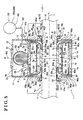
- Fig. 5 is a cross-sectional view of the superconducting rotating electrical machine according to a third embodiment disclosed here, cut along the axial line of the rotary shaft;
- Fig. 6 is a cross-sectional view of the superconducting rotating electrical machine according to a fourth embodiment disclosed here, cut along the axial line of the rotary shaft;
- Fig. 7 is a cross-sectional view of the superconducting rotating electrical machine according to a fifth embodiment disclosed here, cut along the axial line of the rotary shaft;
- Fig. 8 is a cross-sectional view illustrating an inner circumferential portion of the rotary shaft of the superconducting rotating electrical machine according to a sixth embodiment.
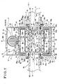
- Fig. 9 is a cross-sectional view of the superconducting rotating electrical machine according to a seventh embodiment, cut along the axial line of the rotary shaft.
- a superconducting rotating electrical machine configures, for example; a motor or generator.
- the superconducting rotating electrical machine includes a base member, a stator supported by the base member, a rotor rotatably provided relative to the stator and formed by a superconducting material, a rotary shaft retaining the rotor, a low temperature container configuring an accommodating chamber, a vacuum heat insulation chamber arranged at an outer side of the accommodating chamber, and bearings at a portion of the base member where the accommodating chamber is prevented from being provided and which is exposed to an ambient atmosphere including atmospheric air.
- the accommodating chamber accommodates the stator, the rotor, and a coolant.
- the vacuum heat insulation chamber insulates the accommodating chamber with vacuum.
- the bearings rotatably support the rotary shaft.
- the motor serves as an induction motor applying an induced current to the rotor.
- the rotor is, for example, a cage motor or a wound rotor.
- the cage motor at least a portion of the cage motor is formed by a superconducting material.
- the rotor is the wound rotor, a coil of the wound rotor is formed by a superconducting material.
- the stator it is preferable for the stator to include a magnetic permeable core formed by a magnetic permeable material and a wound portion retained by the magnetic permeable core.
- the wound portion may be formed by a typical conductive material such as copper wire and the like or by a superconducting material.
- a superconducting magnet and the like may be applied to the superconducting material of the rotor.
- Figs. 1 to 3 illustrate a concept of the superconducting rotating electrical machine according to a first embodiment.
- the first embodiment is an example where the superconducting rotating electrical machine is applied to a superconducting motor.
- the superconducting motor includes a base member 1, a stator 2 generating a rotating magnetic field, a rotor 3 rotatably arranged relative to the stator 2, rotated by the rotating magnetic field of the stator 2, and formed by a superconducting material, a rotary shaft 4 retaining the rotor 3, a cooling portion 5 cooling the stator 2, a low temperature container 6 configuring an accommodating chamber 60, and a vacuum heat insulation chamber 7 arranged at an outer side of the accommodating chamber 60 and surrounding the accommodating chamber 60.
- the accommodating chamber 60 of the low temperature container 6 accommodates the stator 2, the rotor 3, and a gas cooling medium 66 (coolant).
- the accommodating chamber 60 is arranged within the base member 1.
- the base member 1 includes two facing walls 11, 11 facing each other and each having a shaft hole 10, connecting walls 12, 12 connecting outer circumferential end portions of the facing walls 11, 11, respectively, a contacting wall 13 contacting the connecting walls 12, 12, and a connecting wall 15 connecting the outer circumferential end portions of the facing walls 11, 11.
- An outer side of the base member 1 is maintained in an ambient atmosphere and will be referred to as an atmospheric portion 14.
- the atmospheric portion 14 is the ambient atmosphere generally formed by atmospheric air. It is desirable for the atmospheric portion 14 to be maintained at a room temperature or an approximate room temperature or to correspond to the ambient atmosphere under the room temperature.
- the approximate room temperature is in a temperature range that is close to the room temperature rather than to an extremely low temperature.
- the temperature range of the approximate room temperature may be set within a range from 0 to 40 degrees Celsius (plus or minus 20 degrees Celsius of 20 degrees Celsius), a range from 10 to 30 degrees Celsius (plus or minus 10 degrees Celsius of 20 degrees Celsius), and a range from 15 to 25 degrees Celsius (plus or minus 5 degrees Celsius of 20 degrees Celsius).
- the base member 1 is formed by metal, FRP (fiber-reinforced plastic), or ceramics. Further, as shown in Fig. 1 , the base member 1 includes a tubular attachment portion 16 arranged between the facing walls 11, 11 and a second vacuum heat insulation chamber 72 provided at an outer side of the tubular attachment portion 16. Furthermore, a material reducing the leakage of a magnetic flux and having strength is recommended as a material of the base member 1. For example, alloy steel (stainless steel) having a low permeability, hard resin, resin for a reinforcing material, and ceramics are applicable as the material of the base member 1.
- the reinforcing material is an inorganic fiber such as a glass fiber and a ceramic fiber, therefore, the fiber-reinforced plastic is applied in the first embodiment.
- the resin may be either a thermosetting resin or a thermoplastic resin.
- the gas cooling medium 66 as will be described below is prevented from leaking into the vacuum heat insulation chamber 7 because the metal has a high blocking effect relative to the gas cooling medium 66. Accordingly, a reduction of vacuum heat insulation efficiency of the vacuum heat insulation chamber 7 due to the leaking of the gas cooling medium 66 is prevented. Thus, the high vacuum heat insulation efficiency of the vacuum heat insulation chamber 7 is obtained.
- the base member 1 favorably includes the facing walls 11, 11, the connecting walls 12, 12, the contact wall 13, and the connecting wall 15 that are formed by the metallic material, and the tubular attachment portion 16 that is formed by the fiber-reinforced plastic.
- the material of the base member 1 is not limited to the metallic material and the fiber-reinforced plastic.
- the stator 2 is fixedly retained at an inner side of the tubular attachment portion 16.
- the stator 2 includes a magnetic permeable core 20 serving as a fixed iron core and wound portions 21 wound on the magnetic permeable core 20.
- the fixed iron core of the magnetic permeable core 20 is arranged around a central axis P1 of the rotary shaft 4 while having a tubular shape formed by a material that has a high permeability.
- the magnetic permeable core 20 may be formed by a laminated plate laminated on the rotary shaft 4 along the axial direction.
- the magnetic permeable core 20 may be a consolidated aggregation of a number of iron powder particles covered by insulating coating.
- the magnetic permeable core 20 includes a ring portion 22 arranged to surround the central axis P1 and tooth portions 23, which extend from the ring portion 22 to the central axis P1.
- the wound portions 21 are positioned in throttle grooves 23w formed between the tooth portions 23.
- Each of the wound portions 21 is formed by a superconducting material or a copper winding wire that is wound on each of the tooth portions 23 while generating the rotating magnetic field around the central axis P1 in each of positive and negative rotating directions.
- the superconducting material When being cooled to an extremely low temperature state that is equal to or lower than a critical temperature of the superconducting material, the superconducting material is brought into a superconducting state to therefore drastically reduce electrical resistance.
- the critical temperature depends on superconducting materials.
- the critical temperature is set between 4K and 100K.
- Fig. 2 shows only a partial portion of the wound portions 21 wound around the teeth portions 23 and does not illustrate an entire portion of the wound portions 21 wound around the teeth portions 23.
- the wound portions 21 are not illustrated in Fig. 1 in order to prevent Fig. 1 from being unclear.
- the stator 2 and the rotor 3 are simply illustrated in Fig. 1 in order to prevent Fig. 1 from being unclear.
- the rotor 3 is rotatably arranged relative to the stator 2 so as be surrounded thereby.
- the rotor 3 is rotated by the rotating magnetic field of the stator 2 around the central axis P1. Further, the rotor 3 is formed by the superconducting material and brought into the superconductive state when being cooled to the extremely low temperature or lower.
- the superconducting motor according to the first embodiment is a cage induction motor. Accordingly, as seen from Fig. 2 , the rotor 3 includes axial end plates 3a arranged at both axial ends of the rotor 3 in the axial direction and a plurality of rod-shaped members 3c connecting the axial ends of the rotor 3 and circumferentially positioned at intervals from one another.
- the rod-shaped members 3c have electrical conductivity.
- the axial end plates 3a and the rod-shaped members 3c are formed by a superconducting material that reduces electrical resistance drastically or that decreases the electrical resistance to zero.
- an induced current is applied to the rod-shaped members 3 and the like of the rotor 3 due to electromagnetic induction.
- the rotor 3 is electromagnetically induced, the rotor 3 is rotated about the central axis P1 in the positive or negative rotating direction in accordance with a relation between the induced current and the stator 2.
- the rotor 3 is formed in a tubular cage around the central axis P1 while circumferentially including a plurality of pass-through opening portions (see Fig. 2 ).
- the rotary shaft 4 retains an inner circumferential portion 3i of the rotor 3 by means of a fitting portion 32 while being positioned approximately coaxially with the rotor 3.
- the fitting portion 32 has a tubular or ring shape.
- the rotor 3 is retained to an outer circumferential portion 4p of the rotary shaft 4 by the fitting portion 32.
- the rotary shaft 4 is positioned so as to be rotatable in the atmospheric portion 14 maintained at the room temperature or the approximate room temperature. Further, the rotary shaft 4 has a solid shape in the first embodiment.
- the rotary shaft 4 may be formed into a hollow cylinder. Any of metal, ceramics, and FRP (fiber-reinforced plastic) is applicable as a material of the rotary shaft 4. In particular, the FRP having a low thermal conductivity is recommended.
- the cooling portion 5 forcibly cools the stator 2 to the extremely low temperature state and eventually cools the gas cooling medium 66 and the rotor 3 in the accommodating chamber 60 via the stator 2 to a critical temperature or lower (extremely low temperature state) of the rotor 3.
- the cooling portion 5 includes a first thermal conductor 51, a refrigerating device 53 arranged at the base member 1, a compressor 54 activating the refrigerating device 53, a cold head 55 cooled by the refrigerating device 53 to the extremely low temperature state, and a second thermal conductor 52 connecting the cold head 55 to the first thermal conductor 51.
- the first thermal conductor 51 makes thermal contact with a portion of an outer circumferential portion 20p of the magnetic permeable core 20 of the stator 2.
- the refrigerating device 53 is a known refrigerating device such as a pulse tube refrigerator, Stirling refrigerator, Gifford-McMahon refrigerator, Solvey refrigerator, and Vuilleumier refrigerator.
- the second thermal conductor 52 is arranged in the second vacuum heat isolation chamber 72 and configured, for example, by a mesh, plate, or rod member that is formed by a metallic material having a high thermal conductivity.
- a space around the cold head 55 is a vacuum heat insulation portion 55c so that high heat insulation efficiency may be maintained.
- the low temperature container 6 forms the accommodating chamber 60 accommodating the stator 2 and the rotor 3.
- the rotor 3 is arranged radially inward from an inner circumferential portion of the stator 2 in the accommodating chamber 60.
- the gas cooling medium 66 serving as the coolant is filled in the accommodating chamber 60 so as to be accommodated therein.
- the gas is, for example, helium, nitrogen, hydrogen, neon, and the like.
- the low temperature container 6 is formed by a metallic material such as carbon steel, stainless steel, aluminum alloy, and titanium alloy, therefore having a high blocking effect relative to the gas cooling medium 66 and preventing the gas cooling medium coolant 66 in the accommodating chamber 60 from leaking to the outer side of the accommodating chamber 60 (to the vacuum heat isolation chamber 7). Consequently, the vacuum heat isolation chamber 7 may be maintained in a high vacuum state for a long period of time.
- the low temperature container 6 is formed in a shell while including outer circumferential walls 60a, 60a, covering walls 60c, 60c, and inclined walls 60d, 60d.
- Each of the outer circumferential walls 60a, 60a is arranged at the outer circumferential portion 20p of the magnetic permeable core 20 so as to surround the central axis P1.
- the covering walls 60c, 60c cover a first end portion 20e and a second end portion 20f, respectively, of the magnetic permeable core 20 in the axial direction of the rotary shaft 4.
- Each of the inclined walls 60d, 60d is formed in a circular cone extending radially inward from each of the covering walls 60c, 60c.
- the inclined wall 60d is inclined relative to the central axis P1 so as to guide the gas cooling medium 66 radially outward.
- the low temperature container 6 made of metal further includes extending walls 60e, 60e, axial end walls 60h, 60h, and tubular sealing portions 60k, 60k.
- Each of the extending walls 60e, 60e is formed at an inner end portion of the inclined wall 60d so as to extend therefrom along the inner circumferential portion 3i of the rotor 3.
- the axial end walls 60h, 60h face respective axial ends 32e of the fitting portion 32 in the axial direction of the rotary shaft 4.
- each of the tubular sealing portions 60k, 60k is formed at an inner end portion of each of the axial end walls 60h, 60h so as to extend therefrom along the outer circumferential portion 4p of the rotary shaft 4.
- An internal diameter of the tubular sealing portion 60k is substantially uniform in the axial direction of the rotary shaft 4.
- the low temperature container 6 further includes extending walls 60p, 60p each extending radially outwardly from an end portion of the tubular sealing portion 60k.
- Each of the extending walls 60p, 60p is arranged adjacent to an inner surface of the facing wall 11 while facing the covering wall 60c and the inclined wall 60d, thereby separating the vacuum heat insulation chamber 7 from the base member 1.
- the vacuum heat insulation chamber 7 is divided by the low temperature container 6 having the aforementioned shape and configuration, into two sections at right and left sides in a direction indicated by an arrow L shown in Fig. 1 .
- tubular sealing portion 60k facing the outer circumferential portion 4p of the rotary shaft 4 in a condition where a clearance 63 is defined between the tubular sealing portion 60k and the outer circumferential portion 4p in the axial direction of the rotary shaft 4.
- the tubular sealing portion 60k is formed into a hollow right-cylinddrical shape approximately coaxial with the rotary shaft 4 and extending in the axial direction (a direction indicated by an arrow L shown in Fig. 3 ).
- a width t1 of the clearance 63 between the tubular sealing portion 60k and the outer circumferential portion 4p may be set to range from 50 micrometers to 1,200 micrometers, from 100 micrometers to 1,100 micrometers, and from 200 micrometers to 1,000 micrometers; however, the width t1 is not limited to such ranges.
- the tubular sealing portions 60k, 60k are formed so as to further extend toward a central portion of the inner circumferential portion 3i in the axial direction (a direction indicated by an arrow L shown in Fig. 3 ) than first and second axial ends 3e and 3f of the rotor 3. Further, the tubular sealing portions 60k, 60k are positioned adjacent to the axial ends 32e of the fitting portion 32, respectively, of the magnetic permeable core 20 in the axial direction. Accordingly, an axial length LE (see Fig. 3 ) of each of the tubular sealing portions 60k, 60k is secured, therefore increasing a sealing performance of the tubular sealing portions 60k, 60k. As a result, the gas cooling medium 66 in the accommodating chamber 60 is further restricted from leaking therefrom to the vacuum heat insulation chamber 7 and the atmospheric portion 14. In addition, the atmospheric air of the atmospheric portion 14 is prevented from flowing to the accommodating chamber 60.
- the vacuum heat insulation chamber 7 is arranged at the outer side of the accommodating chamber 60 so as to surround the accommodating chamber 60 filled with the gas cooling medium 66.
- the vacuum heat insulation chamber 7 thermally insulates the accommodating chamber 60 with vacuum to thereby maintain the accommodating chamber 60 in a low temperature state that is closer to the extremely low temperature and the like.
- the vacuum heat insulation chamber 7 is provided between the atmospheric portion 14 and the accommodating chamber 60 and thereby isolates the atmospheric portion 14 and the accommodating chamber 60 from each other.
- the vacuum heat insulation chamber 7 includes an outer-circumferential heat insulation chamber 7a, an axial-end heat insulation chamber 7b, and an inner-side heat insulation chamber 7c.
- the outer-circumferential heat insulation chamber 7a covers the outer circumferential portion 20p of the stator 2.
- the axial-end heat insulation chamber 7b covers an outer side of the first and second axial ends 20e and 20f of the stator 2 and an outer side of the first and second axial ends 3e and 3f of the rotor 3.
- the inner-side heat insulation chamber 7c covers portions located in the vicinity of the first and second axial ends 3e and 3f at the inner circumferential portion 3i of the rotor 3.
- the superconducting motor according to the first embodiment includes bearings 8 rotatably supporting the rotary shaft 4 around the central axis P1.
- the bearings 8 each having a ring shape are positioned at a portion of the base member 1 where the accommodating chamber 60 is prevented from being provided and which is exposed to the ambient atmosphere including the atmospheric air.
- the bearings 8 are arranged at the outer circumferential portion 4p of the rotary shaft 4 so as to face the atmospheric portion 14, that is, the bearings 8 are exposed to the atmospheric air at the room temperature or the approximate room temperature.
- the bearings 8 are provided at the right and left sides in the axial direction (direction indicated by the arrow L shown in Fig.
- the width t1 of the clearance 63 is small, variations of the width t1 in a circumferential direction of the rotary shaft 4 are minimized.
- the width t1 may be designed at a small value.
- a plurality of bearings 8 increases coaxiality between the stator 2 and the rotor 3.
- each of the bearings 8 includes an inner race 80 having a ring shape, an outer race 81 having a ring shape, and rolling elements 82.
- a plurality of rolling elements 82 is circumferentially arranged at intervals from one another between the inner race 80 and the outer race 81.
- the inner race 80, the outer race 81, and the rolling elements 82 are formed by metal, ceramic, or hard resin.
- a flanged attachment tube 19 having a tubular shape is formed at the facing wall 11 of the base member 1 so as to be positioned in the vicinity of the rolling elements 82.
- the outer race 81 of the bearing 8 is supported by an inner circumferential surface of the flanged attachment tube 19.
- the inner race 80 is supported by the outer circumferential portion 4p of the rotary shaft 4.
- a stopper portion 19c for the outer race 81 is attached to the flanged attachment tube 19, thereby maintaining a supporting performance of the bearing 8 for a long period of time and securing coaxiality of the rotary shaft 4 with the rotor 3 and the stator 2.
- the stator 2, the rotor 3, and the low temperature container 6 are symmetrically arranged via an imaginary line M2 that is perpendicular to the central axis P1 of the rotary shaft 4.
- Ferrofluidic seals 9 serving as seal portions preventing the gas cooling medium 66 in the accommodating chamber 60 from leaking therefrom are positioned on the outer circumferential portion 4p of the rotary shaft 4 so as to face the outer circumferential portion 4p.
- the Ferrofluidic seals 9 each having a ring shape around the central axis P1 are arranged approximately coaxially with the central axis P1.
- the accommodating chamber 60 is isolated from the atmospheric portion 14 by the Ferrofluidic seals 9, therefore preventing the gas cooling medium 66 filled in the accommodating chamber 60, from leaking therefrom to the atmospheric portion 14.
- the Ferrofluidic seals 9 face the atmospheric portion 14 via the bearings 8 and therefore are maintained in the room temperature or the approximate room temperature.
- Each of the Ferrofluidic seals 9 includes a plurality of magnetic poles (positive and negative poles) and a magnetic fluid increasing a sealing performance between the outer circumferential portion 4p of the rotary shaft 4 and the magnetic poles.
- the plurality of magnetic poles each having a ring shape is arranged next to one another along the axial direction of the rotary shaft 4.
- the magnetic fluid is oriented along magnetic paths formed by the magnetic poles.
- the magnetic fluid includes a base fluid in which fine magnetic particles are stably dispersed with a surface-active agent. It is appropriate for the Ferrofluidic seal 9 to be maintained in the approximate room temperature in order to prevent the magnetic fluid from freezing. When the magnetic fluid freezes to therefore increase the viscosity, a rotational resistance of the rotary shaft 4 increases.
- the Ferrofluidic seals 9 face the outer circumferential portion 4p of the rotary shaft 4 while being supported by the tubular sealing portions 60k, 60k, the extending walls 60p, 60p, and the facing walls 11, 11. Accordingly, heat transmission from the facing wall 11 and the rotary shaft 4 to the Ferrofluidic seal 9 is expected to therefore prevent the Ferrofluidic seal 9 from being excessively cooled.
- the Ferrofluidic seal 9 is arranged between the accommodating chamber 60 and the baring 8 in the axial direction (direction indicated by the arrow L shown in Fig. 1 ) of the rotary shaft 4. That is, the Ferrofluidic seal 9 is positioned between the vacuum heat insulation chamber 7 and the bearing 8.
- a plurality of Ferrofluidic seals 9 (two Ferrofluidic seals 9) is arranged so as to be separated by a space therebetween in the axial direction of the rotary shaft 4 and to be positioned at a further interior side of the base member 1 than the bearings 8 in the axial direction (to be positioned closer to the accommodating chamber 60 than the bearings 8 in the axial direction).
- the Ferrofluidic seal 9 has high air tightness and sealing performance and therefore prevents the gas cooling medium 66 in the accommodating chamber 60 from leaking therefrom even when the gas cooling medium 66 is a coolant such as helium gas and oxygen gas including small molecules. Accordingly, the vacuum heat insulation chamber 7 is appropriately maintained in a vacuum heat insulation state for a long period of time and the gas cooling medium 66 is sufficiently secured in the accommodating chamber 60 for a long period of time.
- the Ferrofluidic seal 9 is arranged to be contact with both an inner circumferential portion of the shaft hole 10 formed in the facing wall 11 of the base member 1, and the vacuum heat insulation chamber 7 in the axial direction of the rotary shaft 4 as shown in Fig. 1 . Accordingly, the heat transmission from the facing wall 11 exposed to the atmospheric air, to the Ferrofluidic seal 9 is expected.
- a plurality of wing portions 33 are formed at the first and second axial ends 3e and 3f of the rotor 3 so as to be positioned in the accommodating chamber 60.
- Each of the wing portions 33 has a fan shape.
- the wing portion 33 may be provided in a different position from the first and second axial ends 3e and 3f according to need.
- the wing portions 33 are rotated along with the rotor 3 around the central axis P1; thereby, the gas cooling medium 66 in the accommodating chamber 60 is shifted and circulated therein by a centrifugal force.
- the gas cooling medium 66 is shifted in a radially outward direction indicated by an arrow W1 shown in Fig. 1 and in a direction indicated by an arrow W2 shown in Fig. 1 by means of the centrifugal force and circulated from the first and second axial ends 20e and 20f to an central area of the stator 2 in the axial direction. Then, the gas cooling medium 66 is circulated from an opening portion 24 of the throttle groove 23w formed between the tooth portions 23 (see Fig. 2 ) along a radial direction (direction indicated by an arrow W3 shown in Fig. 2 and Fig. 3 ) to the rotor 3 and thereafter comes in contact with the rotor 3 so as to cool the rotor 3.
- a small gap 34 is defined between the outer circumferential portion 3p of the rotor 3 and the stator 2 as shown in Fig. 1 .
- the gap 34 having a ring shape allows the rotor 3 to smoothly rotate.
- the wing portion 33 is arranged so as to face the inclined wall 60d of the low temperature container 6. Accordingly, the gas cooling medium 66 shifted by the wing portion 33 comes into contact with the inclined wall 60d and therefore is easily guided in the radially outward direction (indicated by the arrow W1 shown in Fig. 1 ). As a result, the gas cooling medium 66 appropriately comes into contact with the stator 2 that is located in a radially outward direction of the outer circumferential portion 3p of the rotor 3. Additionally, the gas cooling medium 66 is effectively cooled by the stator 2 that is forcibly cooled by the first thermal conductor 51.
- the superconducting motor when the superconducting motor is in operation, a three-phase or single-phase alternating current is applied to the wound portions 21 of the stator 2 via an inverter. Accordingly, the rotating magnetic field is generated around the central axis P1, thereby rotating the rotor 3 along with the rotary shaft 4 and the wing portions 33 around the central axis P1 in the positive or negative rotating direction. Further, when the superconducting motor is in operation, the refrigerating device 53 is driven to cool the cold head 55. As a result, the cold head 55, the second thermal conductor 52, and the first thermal conductor 51 are cooled. Then, the magnetic permeable core 20 and the wound portions 21 that constitute portions of the stator 2 are cooled by the first thermal conductor 51.
- the wing portions 33 are rotated along with the rotation of the rotor 3 around the central axis P1, thereby circulating the gas cooling medium 66 in the accommodating chamber 60. Consequently, the gas cooling medium 66 comes in contact with the stator 2 and therefore is cooled by heat exchange. Then, the gas cooling medium 66 comes into contact with the rotor 3 to thereby forcibly cool the rotor 3, therefore further cooling the rotor 3.
- the superconducting material forming the rotor 3 may be maintained in the extremely low temperature state that is the critical temperature or lower and the superconducting state of the superconducting material may be maintained; thereby, the electrical resistance of the rotor 3 is reduced to zero and a high density of the induced current applied to the rotor 3 is secured.
- torque for rotating the rotor 3 is obtained to increase effectiveness of the superconducting motor accordingly.
- the rotor 3 formed by the superconducting material is accommodated in the accommodating chamber 60. Further, the accommodating chamber 60 is maintained in the low temperature state such as the extremely lower temperature state that is equal to or lower than the critical temperature of the superconducting material, in order to maintain the superconducting state of the superconducting material. Moreover, according to the first embodiment, the bearings 8 rotatably supporting the rotary shaft 4 are positioned at a portion of the base member 1 where the accommodating chamber 60 is prevented from being provided and which is exposed to the ambient atmosphere including the atmospheric air (to the atmospheric portion 14).
- each of the bearing 8 supporting the rotary shaft 4 is arranged between the facing wall 11 of the base member 1 and the outer circumferential portion 4p of the rotary shaft 4 so as to face the atmospheric portion 14. Accordingly, the bearing 8 is maintained in a high temperature range (corresponding to the room temperature or the approximate room temperature), which is at a temperature higher than the low temperature state such as the extremely lower temperature state. Thus, a lubricating agent applied to the bearing 8 is prevented from being excessively cooled and the viscosity of the lubricating agent is inhibited from excessively increasing. As a result, the rotary shaft 4 may be appropriately supported by the bearings 8 so as to be rotatable for a long period of time.
- the bearings 8 when the bearings 8 are arranged so as to face the accommodating chamber 60 that is maintained in the low temperature state as in Reference 1 and Reference 2, the bearings 8 may be easily cooled to the low temperature state such as the extremely low temperature state. In such case, the viscosity of the lubricating agent applied to the bearings 8 may excessively increase, or the lubricating agent may freeze. As a result, the durability of the bearings 8 is drastically reduced. Further, the vacuum heat insulation chamber 7 may be contaminated with the lubricating agent to therefore deteriorate the heat insulation efficiency of the vacuum heat insulation chamber 7. According to the first embodiment, since the bearings 8 are arranged at a portion of the base member 1 where the accommodating chamber 60 is prevented from being provided and which is exposed to the ambient atmosphere including the atmospheric air, the aforementioned adverse conditions seen in Reference 1 and Reference 2 are prevented.
- the lubricating agent applied to the bearings 8 may evaporate.
- the bearings 8 are arranged at a portion of the base member 1 where the accommodating chamber 60 is prevented from being provided and which is exposed to the ambient atmosphere including the atmospheric air, that is, each of the bearings 8 is arranged between the outer circumferential portion 4p of the rotary shaft 4 and the facing wall 11 of the base portion 1 so as to face the atmospheric portion 14. Accordingly, the lubricating agent applied to the bearing 8 may be prevented from evaporating; therefore, the rotary shaft 4 may be appropriately rotatably supported by the bearings 8 for a long period of time. Furthermore, the deterioration of the heat insulation efficiency of the vacuum heat insulation chamber 7 caused by the contamination by the lubricating agent is prevented.
- the width t1 of the clearance 63 defined between the tubular sealing portion 60k and the outer circumferential portion 4p is small; therefore, the sealing performance between an inner circumferential portion 60i of the tubular sealing portion 60k and the outer circumferential portion 4p of the rotary shaft 4 is appropriately secured while the rotary performance of the rotary shaft 4 is secured.
- the tubular sealing portion 60k is positioned approximately coaxially with the rotary shaft 4 along the axial direction; therefore, the above sealing performance is further increased. Accordingly, the gas cooling medium 66 filled in the accommodating chamber 60 is prevented from leaking therefrom to the outer side of the accommodating chamber 60 and the atmospheric air of the atmospheric portion 14 is prevented from flowing in the accommodating chamber 60.
- the width t1 of the clearance 63 is large, the gas cooling medium 66 in the accommodating chamber 60 is prevented from leaking therefrom to an outer side of the Ferrofluidic seal 9; however, the gas cooling medium 66 flows into the clearance 63 that is located at a further inner side than the Ferrofluidic seal 9 in the direction indicated by the arrow L shown in Fig. 1 and Fig. 3 ; therefore, heat transmission such as heat convection caused by the gas cooling medium 66 in the clearance 63 is increased and external heat may be transmitted to the accommodating chamber 60.
- the width t1 of the clearance 63 is small as described above.
- the volume of the gas cooling member 66 flowing into the clearance 63 is extremely reduced. Consequently, the heat transmission such as the heat convection in the clearance 63 is prevented to inhibit the external heat from being transmitted to the accommodating chamber 60.
- a width t2 of the tubular sealing portion 60k is set to be smaller than a thickness t3 of the covering wall 60c (see Fig. 3 ). Accordingly, the transmission of the external heat from atmospheric portion 14 via the tubular seal portion 60k to the accommodating chamber 60 is further limited.
- the Ferrofluidic seal 9 is provided to the superconducting rotating electrical machine, therefore preventing the gas cooling medium 66 in the accommodating chamber 60 from leaking therefrom to the atmospheric portion 14. Further, an outer circumferential portion of the Ferrofluidic seal 9 is covered by the facing wall 11 of the base member 1; therefore, the heat transmission from the facing wall 11 to the Ferrofluidic seal 9 occurs. An inner circumferential portion of the Ferrofluidic seal 9 is circumferentially overlapped by the outer circumferential portion 4p of the rotary shaft 4. Accordingly, heat transmission from the rotary shaft 4 (that is positioned at a temperature higher than a temperature at which the Ferrofluidic seal 9 is positioned) to the Ferrofluidic seal 9 occurs.
- the Ferrofluidic seal 9 is located next to the bearing 8 in the direction indicated by the arrow L; thereby, heat transmission from the bearing 8 to the Ferrofluidic seal 9 occurs (the bearing 8 is positioned at a temperature higher than a temperature at which the Ferrofluidic seal 9 is positioned). Consequently, even when the accommodating chamber 6 accommodating the stator 2 and the rotor 3 that are formed by the superconducting material is maintained in the low temperature state corresponding to the extremely low temperature state, the Ferrofluidic seal 9 is prevented from being excessively cooled and the viscosity of the Ferrofluidic seal 9 is inhibited from excessively increasing. As a result, a lubricating property of the Ferrofluidic seal 9 and the sealing performance of the Ferrofluidic seal 9 are appropriately maintained for a long period of time. Additionally, the rotor 3 may smoothly and appropriately rotate for a long period of time.
- the plurality of rolling elements 82 is circumferentially arranged at intervals at the bearing 8; therefore, the bearing 8 has air permeability in the axial direction.
- a main material of the bearing 8 is the metal that has a high thermal conductivity. Accordingly, the Ferrofluidic seal 9 may be affected by an ambient temperature in the vicinity of the bearing 8. Consequently, even when the accommodating chamber 60 is positioned in the low temperature state corresponding to the extremely low temperature state, the Ferrofluidic seal 9 is prevented from being extremely cooled.
- the Ferrofluidic seal 9 and the bearing 8 are arranged adjacent to each other (within a distance corresponding to an external diameter of the rotary shaft 4) so that the Ferrofluidic seal 9 is positioned at the further interior side than the bearing 8 in the axial direction (direction indicated by the arrow L).
- the bearing 8 prevents the central axis P1 of the rotary shaft 4 from being misaligned in the axial direction when the rotary shaft 4 rotates. Since the Ferrofluidic seal 9 is arranged next to the bearing 8, the axial misalignment of the rotary shaft 4 is appropriately inhibited at the Ferrofluidic seal 9; therefore, the sealing performance of the Ferrofluidic seal 9 is further maintained appropriately for a long period of time.
- FIG. 4 illustrates an example of the Ferrofluidic seal 9.
- the Ferrofluidic seal 9 includes magnet portions 90 having a plurality of magnetic poles (positive and negative poles), spacers 91 each arranged between the magnetic portions 90 arranged next to each other, and a magnetic fluid 93.
- the magnetic poles are arranged adjacent to each other in the axial direction corresponding to a direction indicated by an arrow L shown in Fig. 4 .
- Each of the spacers 91 is formed by a non-magnetic or consistent magnetic material.
- the magnetic fluid 93 is arranged along magnetic paths 92 formed by the positive and negative poles.
- the magnetic fluid 93 increases the sealing performance of the Ferrofluidic seal 9 in the gap 63. It is favorable for the magnetic paths 92 to be separated from one another. Alternatively, the magnetic paths 92 may not be separated from one another.
- the magnetic fluid 93 is a fluid including a base fluid in which magnetic fine particles are maintained in a stably dispersed state by a surface-active agent.
- the base fluid is, for example, hydrocarbon fluid, fluorinated oil, and water; however, the base fluid is not limited to the aforementioned fluids.
- the superconducting motor is provided with a gas cooling medium charge-discharge portion 100 (coolant charge-discharge portion).
- the gas cooling medium charge-discharge portion 100 includes a buffer tank 102, a connecting passage 103, and a valve 104 arranged at the connecting passage 103.
- the buffer tank 102 is arranged at an outer side of the base member 1.
- the connecting passage 103 connects the buffer tank 102 to the accommodating chamber 60.
- the gas cooling medium charge-discharge portion 100 charges and discharges the gas cooling medium 66 to and from the accommodating chamber 60 depending on pressure variations of the gas cooling medium 66 in the accommodating chamber 60.
- a control device commands the compressor 54 to operate to thereby operate the refrigerating device 53.
- the cold head 55 is cooled by the refrigerating device 53 to the extremely low temperature state and the stator 2 is cooled to the extremely low temperature state via the second thermal conductor 52 and the first thermal conductor 51. Consequently, the gas cooling medium 66 accommodated in the accommodating chamber 60 is cooled to the extremely low temperature.
- a pressure of the gas cooling medium 66 in the accommodating chamber 60 is decreased.
- the pressure of the gas cooling medium 66 is decreased to an approximately 25 percent (one fourth). Accordingly, the valve 104 is opened; thereby, the gas cooling medium 66 charged in a tank portion 102c of the buffer tank 102 under high pressure flows into the accommodating chamber 66 under low pressure in accordance with a pressure difference between the tank portion 102c and the accommodating chamber 60.
- the gas cooling medium 66 in the tank portion 102c of the buffer tank 102 is charged to the accommodating chamber 60, thereby increasing cooling capacity of the gas cooling medium 66 in the accommodating chamber 60 relative to the rotor 3.
- the control device commands the compressor 54 to stop operating to stop the operation of the refrigerating device 53. Accordingly, the cooling capacity of the cold head 55 is decreased to therefore raise the temperature of the stator 2. Consequently, the temperature of the gas cooling medium 66 accommodated in the accommodating chamber 60 is raised, thereby increasing the cubic volume of the gas cooling medium 66. At this time, the pressure of the gas cooling medium 66 in the accommodating chamber 60 is increased. As a result, the valve 104 is opened; thereby, the gas cooling medium 66 in the accommodating chamber 60 under high pressure flows into the tank portion 102c of the buffer tank 102 under low pressure in accordance with the pressure difference between the tank portion 102c and the accommodating chamber 60.
- the gas cooling medium charge-discharge portion 100 is utilized to charge the gas cooling medium 66 from the buffer tank 102 to the accommodating chamber 60 and to discharge the gas cooling medium 66 from the accommodating chamber 60 to the tank 102 depending on the temperature of the accommodating chamber 60 and depending on whether or not the superconducting motor is in operation.
- the buffer tank 102 may be arranged at an inner side of the base member 1 instead of the outer side of the base member 1 according to circumstances.
- the buffer tank 102 may be arranged in the vacuum heat insulation chamber 7.
- the fourth embodiment has substantially the same configuration and effects as the aforementioned first, second, and third embodiments. Differences from the first, second, and third embodiments will be mainly described below.
- the rotary shaft 4 according to the fourth embodiment is formed in a hollow shaft while having a third vacuum heat insulation chamber 73 (rotatry-shaft vacuum heat insulation chamber) and partition walls 43, 43.
- the third vacuum heat insulation chamber 73 is positioned so as to face the rotor 3 in the axial direction corresponding to a direction indicated by an arrow L shown in Fig. 6 .
- the partition walls 43, 43 are arranged at an inner circumferential portion of the rotary shaft 4 so as to face each other thereat to section the inner circumferential portion, thereby defining the third vacuum heat insulation chamber 73.
- the third vacuum heat insulation chamber 73 forms an airtight space, which reaches a temperature range from the temperature of the accommodating chamber 60 to the temperature of the atmospheric portion 14. Further, the third vacuum heat insulation chamber 73 is arranged so as to overlap the rotor 3 and the accommodating chamber 60 in the axial direction, therefore having the advantage to prevent the external heat from being transmitted from the atmospheric portion 14 (at the room temperature) to the rotor 3 and the accommodating chamber 60 and to maintain the rotor 3 and the accommodating chamber 60 in the low temperature as much as possible.
- the third vacuum heat insulation chamber 73 that is the airtight space is formed at the inner circumferential portion of the rotary shaft 4, the external heat transferred from the atmospheric portion 14 (at the room temperature) to the rotary shaft 3 and the accommodating chamber 60 is limited.
- an axial length LB of the third vacuum heat insulation chamber 73 in the axial length (direction indicted by an arrow L) is designed to be longer than an axial length LC of the base member 1 in the axial length. Accordingly, each of the partition walls 43, 43 is positioned at a further exterior side than the bearing 8 in the axial direction of the rotary shaft 4 (direction indicated by the arrow L). Thus, the external heat transferred from the atmospheric portion 14 to the rotor 3 and the accommodating chamber 60 via the rotary shaft 4 made of metal is limited.
- the Ferrofluidic seals 9 and the bearings 8 are supported by an outer circumferential wall 40 of the rotary shaft 4 maintained at the room temperature; thereby, the external heat is transferred from the outer circumferential wall 40 to the Ferrofluidic seals 9 and the bearings 8. Accordingly, even when the accommodating chamber 60 accommodating the rotor 3 that includes the superconducting material is maintained in the low temperature state corresponding to the extremely low temperature state, the Ferrofluidic seal 9 and the bearing 8 are prevented from being excessively cooled. Consequently, the outer circumferential wall 40 is preferably formed by a metallic material having an appropriate thermal conductivity and strength (for example, carbon steel, stainless steel, aluminum alloy, copper alloy, and the like). In addition, the outer circumferential wall 40 has a thickness t6 that is set at a predetermined value or more (see Fig. 6 ).
- the rotary shaft 4 according to the fifth embodiment is formed to be the hollow shaft while having the third vacuum heat insulation chamber 73 and the partition walls 43, 43.
- the third vacuum heat insulation chamber 73 is positioned so as to face the rotor 3 in the axial direction corresponding to a direction indicated by an arrow L shown in Fig. 6 .
- the partition walls 43, 43 are arranged at the inner circumferential portion of the rotary shaft 4 so as to face each other to section the inner circumferential portion, thereby defining the third vacuum heat insulation chamber 73.
- the third vacuum heat insulation chamber 73 is arranged at the inner circumferential portion of the rotary shaft 4, heat insulation efficiency of the rotary shaft 4 is increased. Accordingly, the external heat (from the atmospheric portion 14) is restricted from being transferred via the rotary shaft 4 to the accommodating chamber 60 under low temperature.
- the axial length LB of the third vacuum heat insulation chamber 73 in the axial length is designed to be shorter than the axial length LC of the base member 1 in the axial length.
- the Ferrofluidic seals 9 are arranged so as to face an inner hollow space 48 of the rotary shaft 4, which is exposed to the room temperature.
- each of the Ferrofluidic seals 9 is positioned at a further exterior side of each of the partition walls 43, 43 in the axial direction indicated by the arrow L. Accordingly, an inner circumferential portion of the Ferrofluidic seal 9 is at the room temperature (in the ambient atmosphere at the room temperature).
- the Ferrofluidic seal 9 is prevented from being excessively cooled.
- the lubricating property and the sealing performance of the Ferrofluidic seal 9 are appropriately maintained for a long period of time.
- the gas cooling medium 66 filled in the accommodating chamber 60 is prevented from leaking therefrom to the atmospheric portion 14.
- a sixth embodiment of the superconducting rotating electrical machine will be described below with reference to Fig. 8 .
- the sixth embodiment has substantially the same configuration and effects as the aforementioned fourth and fifth embodiments. Differences from the fourth and fifth embodiments will be mainly explained as follows.
- the third vacuum heat insulation chamber 73 under the airtight condition is arranged at the inner circumferential portion of the rotor 4; therefore, the external heat is restricted from being transmitted via the rotary shaft 4 to the accommodating chamber 60 and the rotor 3 that are maintained in the low temperature.
- a gas absorbing agent 46 is provided within the third vacuum heat insulation chamber 73.
- the gas absorbing agent 46 is attached in a tape shape to an inner circumferential surface 73i forming the third vacuum heat insulation chamber 73, thereby being supported thereon.
- the third heat vacuum insulation chamber 73 is maintained in a high vacuum state and in a vacuum heat insulation state for a long period of time.
- a gas absorbing agent having a high absorbability under low temperature is appropriate for the gas absorbing agent 46.
- the gas absorbing agent 46 is, for example, a molecular sieve, an activated charcoal, an oxygen absorbing agent, and the like.
- the molecular sieve includes a zeolite-base material that has a high absorbability.
- the gas absorbing agent 26 may be applied as long as the rotary shaft 4 is configured to include the third heat vacuum insulation chamber 73.
- the gas absorbing agent 46 is desirably uniformly attached to the inner circumferential surface 73i defining the third vacuum heat insulation chamber 73 in order to appropriately align the central axis P1 of the rotary shaft 4. Additionally, the gas absorbing agent 46 formed in a powdered state or a particle state may be filled into the third vacuum heat insulation chamber 73 according to needs. Further alternatively, the gas absorbing agent 46 may be provided in the vacuum heat insulation chamber 7 and/ or the second vacuum heat insulation chamber 72.
- a seventh embodiment of the superconducting rotating electrical machine will be explained as follows with reference to Fig. 9 .
- the seventh embodiment is an example where the superconducting rotating electrical machine is applied to the generator.
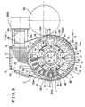
- the seventh embodiment has substantially the same configuration and effects as the aforementioned first, second, third, fourth, fifth, and sixth embodiments. Differences from the first, second, third, fourth, fifth, and sixth embodiments will de mainly described as follows. Since the superconducting rotating electrical machine is applied to the generator, a plurality of permanent magnets 3x is arranged circumferentially at intervals from one another on the rotor 3. Positive and negative poles of the permanent magnets 3x are circumferentially arranged one after the other.
- Each of the permanent magnets 3x is formed by a superconducting bulk magnet and maintained in the low temperature state that is equal to or lower than a critical temperature of the superconducting bulk magnet.
- the superconducting bulk magnet is a superconductor formed in a bulk that is referred to as a superconducting bulk. After being melt, a superconducting material is solidified; thereby, the superconducting bulk is obtained.
- a superconducting bulk synthesized by means of an appropriate composition control is magnetized in a magnetic field
- the small-sized superconducting bulk retains a strong magnetic field indicated by the unit Tesla (T).
- T unit Tesla
- the superconductor is magnetized to be a superconducting bulk material accordingly.
- the aforementioned techniques applied to the superconducting motor may be applied to the generator.
- the generator is further configured so as to have the configurations and effects specially applied in the aforementioned embodiments.
- the Ferrofluidic seal 9 in which the magnetic fluid is utilized is arranged between the outer circumferential portion 4p of the rotary shaft 4 and the shaft hole 10 of the base member 1.
- a seal portion formed by a general organic or non-organic seal material may be applied instead of the Ferrofluidic seal 9.
- the rotor 3 is arranged radially inward from the inner circumferential portion of the stator 2.
- the rotor 3 may be arranged radially outward from the outer circumferential portion of the stator 2.
- the baring 8 includes the inner race 80 having the ring shape, the outer race 81 having the ring shape, and the rolling elements 82.
- the bearing 8 may include an inner race and rolling elements or an outer race and rolling elements.
- the bearing 8 is not limited to a rolling bearing.
- the bearing 8 may be a cylindrical roller bearing, a taper-roller bearing, or a slide bearing.
- the plurality of wing portions 33 is arranged at the first and second axial ends 3e and 3f of the rotor 3.
- the wing portions 33 may be arranged at the rotary shaft 4.
- the gas cooling medium 66 may be replaced by the air.
- the liquid cooling medium has the viscosity slightly higher than the viscosity of the gas cooling medium 66, the liquid cooling medium may be applied instead of the gas cooling medium 66.
- the superconducting rotating electrical machine according to the aforementioned embodiments is applied to the induction motor that is configured so that the induced current is generated at the stator 2 to thereby rotate the rotor 3.
- the superconducting rotating electrical machine according to the embodiments may be applied to a motor including a rotor to which a magnet (superconducting magnet) formed by a superconducting material is attached.
- the superconducting rotating electrical machine is not limited to the induction motor and may be applied to the generator including a rotor to which a magnet portion formed by the superconducting material such as the superconducting bulk magnet is attached.
- the superconducting rotating electrical machine is not limited to the aforementioned embodiments illustrated in the accompanying drawings and may be modified according to needs as long as not departing from the intended purpose of the superconducting rotating electrical machine of the embodiments.
- a superconducting rotating electrical machine configuring a motor or generator includes a base member (1), a stator (2) supported by the base member (2), a rotor (3) rotatably provided relative to the stator (2) and including a superconducting material, a rotary shaft (4) supporting the rotor (2), a cooling portion (5) cooling the stator (2), a low temperature container (6) forming an accommodating chamber (60) accommodating the stator (2), the rotor (3), and a coolant (66), the accommodating chamber (60) being arranged within the base member (1), a vacuum heat insulation chamber (7) arranged at an outer side of the accommodating chamber (60) and thermally insulating the accommodating chamber (60) with vacuum, and a bearing (8) positioned a portion of the base member (1) where the accommodating chamber (60
Landscapes
- Engineering & Computer Science (AREA)
- Power Engineering (AREA)
- Superconductive Dynamoelectric Machines (AREA)
- Motor Or Generator Cooling System (AREA)
Abstract
Description
- This disclosure relates to a superconducting rotating electrical machine configuring a motor or generator.
- A known superconducting motor disclosed in
JP2004-23921A - In the superconducting motor according to
Reference 1, the bearings are arranged in the extremely low temperature state of the case (vacuum heat insulation chamber). Accordingly, a lubricating agent applied to the bearings is also cooled excessively to therefore deteriorate the durability of the bearing. Consequently, a smooth rotating operation of the rotary shaft may be deteriorated. - A known superconducting motor disclosed in
JP2006-149007 Reference 2, the bearings are arranged at the coolant chamber maintained in the extremely low temperature state so as to face each other. Accordingly, the bearings may be extremely cooled by the coolant. Further, a lubricating agent applied to the bearings may be cooled, therefore excessively increasing the viscosity of the lubricating agent. As a result, the durability of the bearings deteriorates; thereby, a smooth rotating operation of the rotary shaft may be deteriorated. - A need thus exists for a superconducting rotating electrical machine, which enables the durability of a bearing supporting a rotary shaft to increase and which allows the rotary shaft to maintain a smooth rotating operation of the rotary shaft for a long period of time.
- According to an aspect of this disclosure, a superconducting rotating electrical machine configuring a motor or generator, includes a base member, a stator supported by the base member, a rotor rotatably provided relative to the stator and including a superconducting material, a rotary shaft supporting the rotor, a cooling portion cooling the stator, a low temperature container forming an accommodating chamber accommodating the stator, the rotor, and a coolant, the accommodating chamber being arranged within the base member, a vacuum heat insulation chamber arranged at an outer side of the accommodating chamber and thermally insulating the accommodating chamber with vacuum, and a bearing positioned a portion of the base member where the accommodating chamber is prevented from being provided and which is exposed to an ambient atmosphere including atmospheric air, the bearing rotatably supporting the rotary shaft.
- Accordingly, the bearing supporting the rotary shaft is arranged at a portion of the base member where the accommodating chamber is prevented from being provided and which is exposed to the ambient atmosphere including the atmospheric air. Accordingly, the bearing is prevented from being maintained in a low temperature state such as an extremely low temperature state when the motor or generator is in operation. Consequently, the bearing is prevented from being excessively cooled and appropriately supported on the rotor shaft for a long period of time. As a result, the rotary shaft supported by the bearing is favorably maintained for a long period of time,
- According to another aspect of the disclosure, the superconducting rotating electrical machine further includes a seal portion at an outer circumferential portion of the rotary shaft to prevent the coolant filled in the accommodating chamber from leaking therefrom.
- Accordingly, the coolant is prevented from leaking from the accommodating chamber.
- According to a further aspect of the disclosure, the seal portion is a Ferrofluidic seal.
- According to a still further aspect of the disclosure, the seal portion is arranged between the accommodating chamber and the bearing.
- According to another aspect of the disclosure, the seal portion is located next to the bearing.
- Accordingly, the bearing prevents the misalignment of the rotary shaft, therefore elongating the life span of the seal portion arranged adjacent to the bearing.
- According to a further aspect of the disclosure, the base member includes facing walls facing each other and each having a shaft hole for the rotary shaft. The seal portion is provided in the shaft hole.
- According to a still further aspect of the disclosure, each of the facing walls is positioned adjacent to the vacuum heat insulation chamber. The seal portion is positioned to be in contact with both the vacuum heat insulation chamber and the facing wall.
- According to another aspect of the disclosure, at least one of the rotor and the rotary shaft includes a wing mechanism having a wing portion and increasing cooling efficiency by circulating the coolant of the accommodating chamber therein.
- Accordingly, the wing mechanism allows the rotor to be further cooled.
- According to a further aspect of the disclosure, the low temperature container includes a tubular sealing portion facing the outer circumferential portion of the rotary shaft in a condition where a clearance is defined between the low temperature container and the outer circumferential portion. The tubular sealing portion extends along an axial direction of the rotary shaft.
- Accordingly, the sealing performance of the tubular sealing portion is appropriately secured while a rotary performance of the rotary shaft is secured.
- According to a still further aspect of the disclosure, the superconducting rotating electrical machine further includes a coolant charge-discharge portion charging and discharging the coolant to and from the accommodating chamber depending on pressure variations of the coolant.
- Accordingly, the coolant may be supplied by the coolant charge-discharge portion according to need, thereby further cooling the rotor.
- The foregoing and additional features and characteristics of this disclosure will become more apparent from the following detailed description considered with the reference to the accompanying drawings, wherein:
-
Fig. 1 is a cross-sectional view of a superconducting rotating electrical machine according to a first embodiment disclosed here, which is cut along an axial line of a rotary shaft; -
Fig. 2 is a cross-sectional view taken along the line II-II ofFig. 1 and illustrating the superconducting rotating electrical machine according to the first embodiment disclosed here, as seen from a direction perpendicular to the axial line of the rotary shaft; -
Fig. 3 is a cross-sectional view of an adjacent area of a Ferrofluidic seal of the superconducting rotating electrical machine according to the first embodiment shown inFig. 1 ; -
Fig. 4 is a perspective view of the Ferrofluidic seal of the superconducting rotating electrical machine according to a second embodiment disclosed here, cut along the axial line of the rotary shaft; -
Fig. 5 is a cross-sectional view of the superconducting rotating electrical machine according to a third embodiment disclosed here, cut along the axial line of the rotary shaft; -
Fig. 6 is a cross-sectional view of the superconducting rotating electrical machine according to a fourth embodiment disclosed here, cut along the axial line of the rotary shaft; -
Fig. 7 is a cross-sectional view of the superconducting rotating electrical machine according to a fifth embodiment disclosed here, cut along the axial line of the rotary shaft; -
Fig. 8 is a cross-sectional view illustrating an inner circumferential portion of the rotary shaft of the superconducting rotating electrical machine according to a sixth embodiment, and -
Fig. 9 is a cross-sectional view of the superconducting rotating electrical machine according to a seventh embodiment, cut along the axial line of the rotary shaft. - A superconducting rotating electrical machine configures, for example; a motor or generator. The superconducting rotating electrical machine includes a base member, a stator supported by the base member, a rotor rotatably provided relative to the stator and formed by a superconducting material, a rotary shaft retaining the rotor, a low temperature container configuring an accommodating chamber, a vacuum heat insulation chamber arranged at an outer side of the accommodating chamber, and bearings at a portion of the base member where the accommodating chamber is prevented from being provided and which is exposed to an ambient atmosphere including atmospheric air. The accommodating chamber accommodates the stator, the rotor, and a coolant. The vacuum heat insulation chamber insulates the accommodating chamber with vacuum. The bearings rotatably support the rotary shaft.
- In the case where the superconducting rotating electrical machine is the motor, the motor serves as an induction motor applying an induced current to the rotor. In this case, the rotor is, for example, a cage motor or a wound rotor. When the rotor is the cage motor, at least a portion of the cage motor is formed by a superconducting material. When the rotor is the wound rotor, a coil of the wound rotor is formed by a superconducting material. It is preferable for the stator to include a magnetic permeable core formed by a magnetic permeable material and a wound portion retained by the magnetic permeable core. The wound portion may be formed by a typical conductive material such as copper wire and the like or by a superconducting material. Further, in the case where the superconducting rotating electrical machine is the generator, a superconducting magnet and the like may be applied to the superconducting material of the rotor.
-
Figs. 1 to 3 illustrate a concept of the superconducting rotating electrical machine according to a first embodiment. The first embodiment is an example where the superconducting rotating electrical machine is applied to a superconducting motor. As illustrated inFig. 1 , the superconducting motor includes abase member 1, astator 2 generating a rotating magnetic field, arotor 3 rotatably arranged relative to thestator 2, rotated by the rotating magnetic field of thestator 2, and formed by a superconducting material, arotary shaft 4 retaining therotor 3, a coolingportion 5 cooling thestator 2, alow temperature container 6 configuring anaccommodating chamber 60, and a vacuumheat insulation chamber 7 arranged at an outer side of theaccommodating chamber 60 and surrounding theaccommodating chamber 60. Theaccommodating chamber 60 of thelow temperature container 6 accommodates thestator 2, therotor 3, and a gas cooling medium 66 (coolant). Theaccommodating chamber 60 is arranged within thebase member 1. - As shown in
Fig. 1 , thebase member 1 includes two facingwalls shaft hole 10, connectingwalls walls wall 13 contacting the connectingwalls wall 15 connecting the outer circumferential end portions of the facingwalls base member 1 is maintained in an ambient atmosphere and will be referred to as anatmospheric portion 14. Theatmospheric portion 14 is the ambient atmosphere generally formed by atmospheric air. It is desirable for theatmospheric portion 14 to be maintained at a room temperature or an approximate room temperature or to correspond to the ambient atmosphere under the room temperature. The approximate room temperature is in a temperature range that is close to the room temperature rather than to an extremely low temperature. The temperature range of the approximate room temperature may be set within a range from 0 to 40 degrees Celsius (plus or minus 20 degrees Celsius of 20 degrees Celsius), a range from 10 to 30 degrees Celsius (plus or minus 10 degrees Celsius of 20 degrees Celsius), and a range from 15 to 25 degrees Celsius (plus or minus 5 degrees Celsius of 20 degrees Celsius). - The
base member 1 is formed by metal, FRP (fiber-reinforced plastic), or ceramics. Further, as shown inFig. 1 , thebase member 1 includes atubular attachment portion 16 arranged between the facingwalls heat insulation chamber 72 provided at an outer side of thetubular attachment portion 16. Furthermore, a material reducing the leakage of a magnetic flux and having strength is recommended as a material of thebase member 1. For example, alloy steel (stainless steel) having a low permeability, hard resin, resin for a reinforcing material, and ceramics are applicable as the material of thebase member 1. The reinforcing material is an inorganic fiber such as a glass fiber and a ceramic fiber, therefore, the fiber-reinforced plastic is applied in the first embodiment. The resin may be either a thermosetting resin or a thermoplastic resin. Here, when the material of thebase member 1 is a metallic material, thegas cooling medium 66 as will be described below is prevented from leaking into the vacuumheat insulation chamber 7 because the metal has a high blocking effect relative to thegas cooling medium 66. Accordingly, a reduction of vacuum heat insulation efficiency of the vacuumheat insulation chamber 7 due to the leaking of thegas cooling medium 66 is prevented. Thus, the high vacuum heat insulation efficiency of the vacuumheat insulation chamber 7 is obtained. Thebase member 1 favorably includes the facingwalls walls contact wall 13, and the connectingwall 15 that are formed by the metallic material, and thetubular attachment portion 16 that is formed by the fiber-reinforced plastic. However, the material of thebase member 1 is not limited to the metallic material and the fiber-reinforced plastic. - As illustrated in
Fig. 2 , thestator 2 is fixedly retained at an inner side of thetubular attachment portion 16. Thestator 2 includes a magneticpermeable core 20 serving as a fixed iron core and woundportions 21 wound on the magneticpermeable core 20. The fixed iron core of the magneticpermeable core 20 is arranged around a central axis P1 of therotary shaft 4 while having a tubular shape formed by a material that has a high permeability. Alternatively, the magneticpermeable core 20 may be formed by a laminated plate laminated on therotary shaft 4 along the axial direction. Further, the magneticpermeable core 20 may be a consolidated aggregation of a number of iron powder particles covered by insulating coating. The magneticpermeable core 20 includes aring portion 22 arranged to surround the central axis P1 andtooth portions 23, which extend from thering portion 22 to the central axis P1. Thewound portions 21 are positioned inthrottle grooves 23w formed between thetooth portions 23. Each of thewound portions 21 is formed by a superconducting material or a copper winding wire that is wound on each of thetooth portions 23 while generating the rotating magnetic field around the central axis P1 in each of positive and negative rotating directions. When being cooled to an extremely low temperature state that is equal to or lower than a critical temperature of the superconducting material, the superconducting material is brought into a superconducting state to therefore drastically reduce electrical resistance. The critical temperature depends on superconducting materials. For example, the critical temperature is set between 4K and 100K.Fig. 2 shows only a partial portion of thewound portions 21 wound around theteeth portions 23 and does not illustrate an entire portion of thewound portions 21 wound around theteeth portions 23. Thewound portions 21 are not illustrated inFig. 1 in order to preventFig. 1 from being unclear. Further, thestator 2 and therotor 3 are simply illustrated inFig. 1 in order to preventFig. 1 from being unclear. - The
rotor 3 is rotatably arranged relative to thestator 2 so as be surrounded thereby. Therotor 3 is rotated by the rotating magnetic field of thestator 2 around the central axis P1. Further, therotor 3 is formed by the superconducting material and brought into the superconductive state when being cooled to the extremely low temperature or lower. The superconducting motor according to the first embodiment is a cage induction motor. Accordingly, as seen fromFig. 2 , therotor 3 includesaxial end plates 3a arranged at both axial ends of therotor 3 in the axial direction and a plurality of rod-shapedmembers 3c connecting the axial ends of therotor 3 and circumferentially positioned at intervals from one another. The rod-shapedmembers 3c have electrical conductivity. Theaxial end plates 3a and the rod-shapedmembers 3c are formed by a superconducting material that reduces electrical resistance drastically or that decreases the electrical resistance to zero. Here, when the rotating magnetic field is generated by thestator 2 around the central axis P1, an induced current is applied to the rod-shapedmembers 3 and the like of therotor 3 due to electromagnetic induction. Then, when therotor 3 is electromagnetically induced, therotor 3 is rotated about the central axis P1 in the positive or negative rotating direction in accordance with a relation between the induced current and thestator 2. - The
rotor 3 is formed in a tubular cage around the central axis P1 while circumferentially including a plurality of pass-through opening portions (seeFig. 2 ). Therotary shaft 4 retains aninner circumferential portion 3i of therotor 3 by means of afitting portion 32 while being positioned approximately coaxially with therotor 3. Thefitting portion 32 has a tubular or ring shape. Therotor 3 is retained to an outercircumferential portion 4p of therotary shaft 4 by thefitting portion 32. Therotary shaft 4 is positioned so as to be rotatable in theatmospheric portion 14 maintained at the room temperature or the approximate room temperature. Further, therotary shaft 4 has a solid shape in the first embodiment. Alternatively, therotary shaft 4 may be formed into a hollow cylinder. Any of metal, ceramics, and FRP (fiber-reinforced plastic) is applicable as a material of therotary shaft 4. In particular, the FRP having a low thermal conductivity is recommended. - The cooling
portion 5 forcibly cools thestator 2 to the extremely low temperature state and eventually cools thegas cooling medium 66 and therotor 3 in theaccommodating chamber 60 via thestator 2 to a critical temperature or lower (extremely low temperature state) of therotor 3. As illustrated inFig. 2 , the coolingportion 5 includes a firstthermal conductor 51, a refrigeratingdevice 53 arranged at thebase member 1, acompressor 54 activating the refrigeratingdevice 53, acold head 55 cooled by the refrigeratingdevice 53 to the extremely low temperature state, and a secondthermal conductor 52 connecting thecold head 55 to the firstthermal conductor 51. The firstthermal conductor 51 makes thermal contact with a portion of an outercircumferential portion 20p of the magneticpermeable core 20 of thestator 2. The refrigeratingdevice 53 is a known refrigerating device such as a pulse tube refrigerator, Stirling refrigerator, Gifford-McMahon refrigerator, Solvey refrigerator, and Vuilleumier refrigerator. The secondthermal conductor 52 is arranged in the second vacuumheat isolation chamber 72 and configured, for example, by a mesh, plate, or rod member that is formed by a metallic material having a high thermal conductivity. A space around thecold head 55 is a vacuumheat insulation portion 55c so that high heat insulation efficiency may be maintained. - As illustrated in
Fig. 2 , thelow temperature container 6 forms theaccommodating chamber 60 accommodating thestator 2 and therotor 3. Therotor 3 is arranged radially inward from an inner circumferential portion of thestator 2 in theaccommodating chamber 60. Thegas cooling medium 66 serving as the coolant is filled in theaccommodating chamber 60 so as to be accommodated therein. Gas that does not solidify and condense at a temperature that is the critical temperature or lower of the superconducting material, or at an operating temperature of the superconducting rotating electrical machine, is selected as thegas cooling medium 66. The gas is, for example, helium, nitrogen, hydrogen, neon, and the like. Thelow temperature container 6 is formed by a metallic material such as carbon steel, stainless steel, aluminum alloy, and titanium alloy, therefore having a high blocking effect relative to thegas cooling medium 66 and preventing the gas coolingmedium coolant 66 in theaccommodating chamber 60 from leaking to the outer side of the accommodating chamber 60 (to the vacuum heat isolation chamber 7). Consequently, the vacuumheat isolation chamber 7 may be maintained in a high vacuum state for a long period of time. - As shown in
Fig. 1 , thelow temperature container 6 is formed in a shell while including outercircumferential walls walls inclined walls circumferential walls circumferential portion 20p of the magneticpermeable core 20 so as to surround the central axis P1. The coveringwalls first end portion 20e and asecond end portion 20f, respectively, of the magneticpermeable core 20 in the axial direction of therotary shaft 4. Each of theinclined walls walls inclined wall 60d is inclined relative to the central axis P1 so as to guide thegas cooling medium 66 radially outward. Thelow temperature container 6 made of metal further includes extendingwalls axial end walls tubular sealing portions walls inclined wall 60d so as to extend therefrom along theinner circumferential portion 3i of therotor 3. Theaxial end walls fitting portion 32 in the axial direction of therotary shaft 4. Each of thetubular sealing portions axial end walls circumferential portion 4p of therotary shaft 4. An internal diameter of thetubular sealing portion 60k is substantially uniform in the axial direction of therotary shaft 4. As illustrated inFig. 1 , thelow temperature container 6 further includes extendingwalls tubular sealing portion 60k. Each of the extendingwalls wall 11 while facing the coveringwall 60c and theinclined wall 60d, thereby separating the vacuumheat insulation chamber 7 from thebase member 1. The vacuumheat insulation chamber 7 is divided by thelow temperature container 6 having the aforementioned shape and configuration, into two sections at right and left sides in a direction indicated by an arrow L shown inFig. 1 . - As illustrated in
Fig. 3 , thetubular sealing portion 60k facing the outercircumferential portion 4p of therotary shaft 4 in a condition where aclearance 63 is defined between thetubular sealing portion 60k and the outercircumferential portion 4p in the axial direction of therotary shaft 4. Further, thetubular sealing portion 60k is formed into a hollow right-cylinddrical shape approximately coaxial with therotary shaft 4 and extending in the axial direction (a direction indicated by an arrow L shown inFig. 3 ). A width t1 of theclearance 63 between thetubular sealing portion 60k and the outercircumferential portion 4p may be set to range from 50 micrometers to 1,200 micrometers, from 100 micrometers to 1,100 micrometers, and from 200 micrometers to 1,000 micrometers; however, the width t1 is not limited to such ranges. - As shown in
Fig. 1 , thetubular sealing portions inner circumferential portion 3i in the axial direction (a direction indicated by an arrow L shown inFig. 3 ) than first and second axial ends 3e and 3f of therotor 3. Further, thetubular sealing portions fitting portion 32, respectively, of the magneticpermeable core 20 in the axial direction. Accordingly, an axial length LE (seeFig. 3 ) of each of thetubular sealing portions tubular sealing portions gas cooling medium 66 in theaccommodating chamber 60 is further restricted from leaking therefrom to the vacuumheat insulation chamber 7 and theatmospheric portion 14. In addition, the atmospheric air of theatmospheric portion 14 is prevented from flowing to theaccommodating chamber 60. - As illustrated in
Fig. 1 , the vacuumheat insulation chamber 7 is arranged at the outer side of theaccommodating chamber 60 so as to surround theaccommodating chamber 60 filled with thegas cooling medium 66. The vacuumheat insulation chamber 7 thermally insulates theaccommodating chamber 60 with vacuum to thereby maintain theaccommodating chamber 60 in a low temperature state that is closer to the extremely low temperature and the like. The vacuumheat insulation chamber 7 is provided between theatmospheric portion 14 and theaccommodating chamber 60 and thereby isolates theatmospheric portion 14 and theaccommodating chamber 60 from each other. Further, as shown inFig. 1 , the vacuumheat insulation chamber 7 includes an outer-circumferentialheat insulation chamber 7a, an axial-endheat insulation chamber 7b, and an inner-sideheat insulation chamber 7c. The outer-circumferentialheat insulation chamber 7a covers the outercircumferential portion 20p of thestator 2. The axial-endheat insulation chamber 7b covers an outer side of the first and second axial ends 20e and 20f of thestator 2 and an outer side of the first and second axial ends 3e and 3f of therotor 3. The inner-sideheat insulation chamber 7c covers portions located in the vicinity of the first and second axial ends 3e and 3f at theinner circumferential portion 3i of therotor 3. Thus, a thermal contactability of thegas cooling medium 66 with thestator 2 and therotor 3 is secured; therefore, a forcible cooling by using thegas cooling medium 66 is performed. Viscosity of thegas cooling medium 66 is relatively low compared to viscosity of a liquid coolant. Accordingly, a rotary performance of therotor 3 is not deteriorated. - The superconducting motor according to the first embodiment includes
bearings 8 rotatably supporting therotary shaft 4 around the central axis P1. As shown inFig. 1 , thebearings 8 each having a ring shape are positioned at a portion of thebase member 1 where theaccommodating chamber 60 is prevented from being provided and which is exposed to the ambient atmosphere including the atmospheric air. Further, thebearings 8 are arranged at the outercircumferential portion 4p of therotary shaft 4 so as to face theatmospheric portion 14, that is, thebearings 8 are exposed to the atmospheric air at the room temperature or the approximate room temperature. Furthermore, thebearings 8 are provided at the right and left sides in the axial direction (direction indicated by the arrow L shown inFig. 1 ), therefore preventing therotor 3 from being misaligned around the central axis P1 and desirably maintaining the rotary performance of therotor 3. Accordingly, even in the case where the width t1 of theclearance 63 is small, variations of the width t1 in a circumferential direction of therotary shaft 4 are minimized. As a result, the width t1 may be designed at a small value. Thus, a plurality ofbearings 8 increases coaxiality between thestator 2 and therotor 3. - As illustrated in
Fig. 1 andFig. 3 , each of thebearings 8 includes aninner race 80 having a ring shape, anouter race 81 having a ring shape, and rollingelements 82. A plurality of rollingelements 82 is circumferentially arranged at intervals from one another between theinner race 80 and theouter race 81. Theinner race 80, theouter race 81, and the rollingelements 82 are formed by metal, ceramic, or hard resin. Aflanged attachment tube 19 having a tubular shape is formed at the facingwall 11 of thebase member 1 so as to be positioned in the vicinity of the rollingelements 82. Theouter race 81 of thebearing 8 is supported by an inner circumferential surface of theflanged attachment tube 19. Theinner race 80 is supported by the outercircumferential portion 4p of therotary shaft 4. Astopper portion 19c for theouter race 81 is attached to theflanged attachment tube 19, thereby maintaining a supporting performance of thebearing 8 for a long period of time and securing coaxiality of therotary shaft 4 with therotor 3 and thestator 2. In addition, as shown inFig. 1 , thestator 2, therotor 3, and thelow temperature container 6 are symmetrically arranged via an imaginary line M2 that is perpendicular to the central axis P1 of therotary shaft 4. - As shown in
Fig. 1 , Ferrofluidic seals 9 serving as seal portions preventing thegas cooling medium 66 in theaccommodating chamber 60 from leaking therefrom are positioned on the outercircumferential portion 4p of therotary shaft 4 so as to face the outercircumferential portion 4p. The Ferrofluidic seals 9 each having a ring shape around the central axis P1 are arranged approximately coaxially with the central axis P1. Theaccommodating chamber 60 is isolated from theatmospheric portion 14 by the Ferrofluidic seals 9, therefore preventing thegas cooling medium 66 filled in theaccommodating chamber 60, from leaking therefrom to theatmospheric portion 14. The Ferrofluidic seals 9 face theatmospheric portion 14 via thebearings 8 and therefore are maintained in the room temperature or the approximate room temperature. Each of the Ferrofluidic seals 9 includes a plurality of magnetic poles (positive and negative poles) and a magnetic fluid increasing a sealing performance between the outercircumferential portion 4p of therotary shaft 4 and the magnetic poles. The plurality of magnetic poles each having a ring shape is arranged next to one another along the axial direction of therotary shaft 4. The magnetic fluid is oriented along magnetic paths formed by the magnetic poles. The magnetic fluid includes a base fluid in which fine magnetic particles are stably dispersed with a surface-active agent. It is appropriate for theFerrofluidic seal 9 to be maintained in the approximate room temperature in order to prevent the magnetic fluid from freezing. When the magnetic fluid freezes to therefore increase the viscosity, a rotational resistance of therotary shaft 4 increases. In addition, as shown inFig. 1 andFig. 3 , the Ferrofluidic seals 9 face the outercircumferential portion 4p of therotary shaft 4 while being supported by thetubular sealing portions walls walls wall 11 and therotary shaft 4 to theFerrofluidic seal 9 is expected to therefore prevent theFerrofluidic seal 9 from being excessively cooled. - As illustrated in
Fig. 1 , theFerrofluidic seal 9 is arranged between theaccommodating chamber 60 and the baring 8 in the axial direction (direction indicated by the arrow L shown inFig. 1 ) of therotary shaft 4. That is, theFerrofluidic seal 9 is positioned between the vacuumheat insulation chamber 7 and thebearing 8. In other words, a plurality of Ferrofluidic seals 9 (two Ferrofluidic seals 9) is arranged so as to be separated by a space therebetween in the axial direction of therotary shaft 4 and to be positioned at a further interior side of thebase member 1 than thebearings 8 in the axial direction (to be positioned closer to theaccommodating chamber 60 than thebearings 8 in the axial direction). TheFerrofluidic seal 9 has high air tightness and sealing performance and therefore prevents thegas cooling medium 66 in theaccommodating chamber 60 from leaking therefrom even when thegas cooling medium 66 is a coolant such as helium gas and oxygen gas including small molecules. Accordingly, the vacuumheat insulation chamber 7 is appropriately maintained in a vacuum heat insulation state for a long period of time and thegas cooling medium 66 is sufficiently secured in theaccommodating chamber 60 for a long period of time. In addition, theFerrofluidic seal 9 is arranged to be contact with both an inner circumferential portion of theshaft hole 10 formed in the facingwall 11 of thebase member 1, and the vacuumheat insulation chamber 7 in the axial direction of therotary shaft 4 as shown inFig. 1 . Accordingly, the heat transmission from the facingwall 11 exposed to the atmospheric air, to theFerrofluidic seal 9 is expected. - As shown in
Fig. 1 , a plurality of wing portions 33 (included in a wing mechanism) are formed at the first and second axial ends 3e and 3f of therotor 3 so as to be positioned in theaccommodating chamber 60. Each of thewing portions 33 has a fan shape. Thewing portion 33 may be provided in a different position from the first and second axial ends 3e and 3f according to need. Thewing portions 33 are rotated along with therotor 3 around the central axis P1; thereby, thegas cooling medium 66 in theaccommodating chamber 60 is shifted and circulated therein by a centrifugal force. As a result, thegas cooling medium 66 is shifted in a radially outward direction indicated by an arrow W1 shown inFig. 1 and in a direction indicated by an arrow W2 shown inFig. 1 by means of the centrifugal force and circulated from the first and second axial ends 20e and 20f to an central area of thestator 2 in the axial direction. Then, thegas cooling medium 66 is circulated from an openingportion 24 of thethrottle groove 23w formed between the tooth portions 23 (seeFig. 2 ) along a radial direction (direction indicated by an arrow W3 shown inFig. 2 andFig. 3 ) to therotor 3 and thereafter comes in contact with therotor 3 so as to cool therotor 3. In addition, asmall gap 34 is defined between the outercircumferential portion 3p of therotor 3 and thestator 2 as shown inFig. 1 . Thegap 34 having a ring shape allows therotor 3 to smoothly rotate. - As illustrated in
Fig. 1 , thewing portion 33 is arranged so as to face theinclined wall 60d of thelow temperature container 6. Accordingly, thegas cooling medium 66 shifted by thewing portion 33 comes into contact with theinclined wall 60d and therefore is easily guided in the radially outward direction (indicated by the arrow W1 shown inFig. 1 ). As a result, thegas cooling medium 66 appropriately comes into contact with thestator 2 that is located in a radially outward direction of the outercircumferential portion 3p of therotor 3. Additionally, thegas cooling medium 66 is effectively cooled by thestator 2 that is forcibly cooled by the firstthermal conductor 51. - For example, when the superconducting motor is in operation, a three-phase or single-phase alternating current is applied to the
wound portions 21 of thestator 2 via an inverter. Accordingly, the rotating magnetic field is generated around the central axis P1, thereby rotating therotor 3 along with therotary shaft 4 and thewing portions 33 around the central axis P1 in the positive or negative rotating direction. Further, when the superconducting motor is in operation, the refrigeratingdevice 53 is driven to cool thecold head 55. As a result, thecold head 55, the secondthermal conductor 52, and the firstthermal conductor 51 are cooled. Then, the magneticpermeable core 20 and thewound portions 21 that constitute portions of thestator 2 are cooled by the firstthermal conductor 51. At this time, thewing portions 33 are rotated along with the rotation of therotor 3 around the central axis P1, thereby circulating thegas cooling medium 66 in theaccommodating chamber 60. Consequently, thegas cooling medium 66 comes in contact with thestator 2 and therefore is cooled by heat exchange. Then, thegas cooling medium 66 comes into contact with therotor 3 to thereby forcibly cool therotor 3, therefore further cooling therotor 3. As a result, the superconducting material forming therotor 3 may be maintained in the extremely low temperature state that is the critical temperature or lower and the superconducting state of the superconducting material may be maintained; thereby, the electrical resistance of therotor 3 is reduced to zero and a high density of the induced current applied to therotor 3 is secured. Thus, torque for rotating therotor 3 is obtained to increase effectiveness of the superconducting motor accordingly. - As described above, according to the first embodiment, the
rotor 3 formed by the superconducting material is accommodated in theaccommodating chamber 60. Further, theaccommodating chamber 60 is maintained in the low temperature state such as the extremely lower temperature state that is equal to or lower than the critical temperature of the superconducting material, in order to maintain the superconducting state of the superconducting material. Moreover, according to the first embodiment, thebearings 8 rotatably supporting therotary shaft 4 are positioned at a portion of thebase member 1 where theaccommodating chamber 60 is prevented from being provided and which is exposed to the ambient atmosphere including the atmospheric air (to the atmospheric portion 14). In particular, each of thebearing 8 supporting therotary shaft 4 is arranged between the facingwall 11 of thebase member 1 and the outercircumferential portion 4p of therotary shaft 4 so as to face theatmospheric portion 14. Accordingly, thebearing 8 is maintained in a high temperature range (corresponding to the room temperature or the approximate room temperature), which is at a temperature higher than the low temperature state such as the extremely lower temperature state. Thus, a lubricating agent applied to thebearing 8 is prevented from being excessively cooled and the viscosity of the lubricating agent is inhibited from excessively increasing. As a result, therotary shaft 4 may be appropriately supported by thebearings 8 so as to be rotatable for a long period of time. - For example, when the
bearings 8 are arranged so as to face theaccommodating chamber 60 that is maintained in the low temperature state as inReference 1 andReference 2, thebearings 8 may be easily cooled to the low temperature state such as the extremely low temperature state. In such case, the viscosity of the lubricating agent applied to thebearings 8 may excessively increase, or the lubricating agent may freeze. As a result, the durability of thebearings 8 is drastically reduced. Further, the vacuumheat insulation chamber 7 may be contaminated with the lubricating agent to therefore deteriorate the heat insulation efficiency of the vacuumheat insulation chamber 7. According to the first embodiment, since thebearings 8 are arranged at a portion of thebase member 1 where theaccommodating chamber 60 is prevented from being provided and which is exposed to the ambient atmosphere including the atmospheric air, the aforementioned adverse conditions seen inReference 1 andReference 2 are prevented. - Moreover, for example, when the
bearings 8 are arranged in the vacuumheat insulation chamber 7, the lubricating agent applied to thebearings 8 may evaporate. According to the first embodiment, thebearings 8 are arranged at a portion of thebase member 1 where theaccommodating chamber 60 is prevented from being provided and which is exposed to the ambient atmosphere including the atmospheric air, that is, each of thebearings 8 is arranged between the outercircumferential portion 4p of therotary shaft 4 and the facingwall 11 of thebase portion 1 so as to face theatmospheric portion 14. Accordingly, the lubricating agent applied to thebearing 8 may be prevented from evaporating; therefore, therotary shaft 4 may be appropriately rotatably supported by thebearings 8 for a long period of time. Furthermore, the deterioration of the heat insulation efficiency of the vacuumheat insulation chamber 7 caused by the contamination by the lubricating agent is prevented. - In addition, according to the first embodiment, the width t1 of the
clearance 63 defined between thetubular sealing portion 60k and the outercircumferential portion 4p is small; therefore, the sealing performance between an innercircumferential portion 60i of thetubular sealing portion 60k and the outercircumferential portion 4p of therotary shaft 4 is appropriately secured while the rotary performance of therotary shaft 4 is secured. Further, thetubular sealing portion 60k is positioned approximately coaxially with therotary shaft 4 along the axial direction; therefore, the above sealing performance is further increased. Accordingly, thegas cooling medium 66 filled in theaccommodating chamber 60 is prevented from leaking therefrom to the outer side of theaccommodating chamber 60 and the atmospheric air of theatmospheric portion 14 is prevented from flowing in theaccommodating chamber 60. - Meanwhile, for example, when the width t1 of the
clearance 63 is large, thegas cooling medium 66 in theaccommodating chamber 60 is prevented from leaking therefrom to an outer side of theFerrofluidic seal 9; however, thegas cooling medium 66 flows into theclearance 63 that is located at a further inner side than theFerrofluidic seal 9 in the direction indicated by the arrow L shown inFig. 1 andFig. 3 ; therefore, heat transmission such as heat convection caused by thegas cooling medium 66 in theclearance 63 is increased and external heat may be transmitted to theaccommodating chamber 60. According to the first embodiment, the width t1 of theclearance 63 is small as described above. Accordingly, even when thegas cooling medium 66 in theaccommodating chamber 60 flows into theclearance 63, the volume of thegas cooling member 66 flowing into theclearance 63 is extremely reduced. Consequently, the heat transmission such as the heat convection in theclearance 63 is prevented to inhibit the external heat from being transmitted to theaccommodating chamber 60. - Additionally, a width t2 of the
tubular sealing portion 60k is set to be smaller than a thickness t3 of the coveringwall 60c (seeFig. 3 ). Accordingly, the transmission of the external heat fromatmospheric portion 14 via thetubular seal portion 60k to theaccommodating chamber 60 is further limited. - According to the first embodiment, the
Ferrofluidic seal 9 is provided to the superconducting rotating electrical machine, therefore preventing thegas cooling medium 66 in theaccommodating chamber 60 from leaking therefrom to theatmospheric portion 14. Further, an outer circumferential portion of theFerrofluidic seal 9 is covered by the facingwall 11 of thebase member 1; therefore, the heat transmission from the facingwall 11 to theFerrofluidic seal 9 occurs. An inner circumferential portion of theFerrofluidic seal 9 is circumferentially overlapped by the outercircumferential portion 4p of therotary shaft 4. Accordingly, heat transmission from the rotary shaft 4 (that is positioned at a temperature higher than a temperature at which theFerrofluidic seal 9 is positioned) to theFerrofluidic seal 9 occurs. Furthermore, theFerrofluidic seal 9 is located next to thebearing 8 in the direction indicated by the arrow L; thereby, heat transmission from thebearing 8 to theFerrofluidic seal 9 occurs (thebearing 8 is positioned at a temperature higher than a temperature at which theFerrofluidic seal 9 is positioned). Consequently, even when theaccommodating chamber 6 accommodating thestator 2 and therotor 3 that are formed by the superconducting material is maintained in the low temperature state corresponding to the extremely low temperature state, theFerrofluidic seal 9 is prevented from being excessively cooled and the viscosity of theFerrofluidic seal 9 is inhibited from excessively increasing. As a result, a lubricating property of theFerrofluidic seal 9 and the sealing performance of theFerrofluidic seal 9 are appropriately maintained for a long period of time. Additionally, therotor 3 may smoothly and appropriately rotate for a long period of time. - According to the first embodiment, the plurality of rolling
elements 82 is circumferentially arranged at intervals at thebearing 8; therefore, thebearing 8 has air permeability in the axial direction. Further, a main material of thebearing 8 is the metal that has a high thermal conductivity. Accordingly, theFerrofluidic seal 9 may be affected by an ambient temperature in the vicinity of thebearing 8. Consequently, even when theaccommodating chamber 60 is positioned in the low temperature state corresponding to the extremely low temperature state, theFerrofluidic seal 9 is prevented from being extremely cooled. - As illustrated in
Fig. 1 , theFerrofluidic seal 9 and thebearing 8 are arranged adjacent to each other (within a distance corresponding to an external diameter of the rotary shaft 4) so that theFerrofluidic seal 9 is positioned at the further interior side than thebearing 8 in the axial direction (direction indicated by the arrow L). Here, thebearing 8 prevents the central axis P1 of therotary shaft 4 from being misaligned in the axial direction when therotary shaft 4 rotates. Since theFerrofluidic seal 9 is arranged next to thebearing 8, the axial misalignment of therotary shaft 4 is appropriately inhibited at theFerrofluidic seal 9; therefore, the sealing performance of theFerrofluidic seal 9 is further maintained appropriately for a long period of time. - A second embodiment of the superconducting rotating electrical machine will be explained as follows with reference to
Fig. 4 . The second embodiment has substantially the same configuration and effects as the first embodiment. Differences from the first embodiment will be mainly described below.Fig. 4 illustrates an example of theFerrofluidic seal 9. As shown inFig. 4 , theFerrofluidic seal 9 includesmagnet portions 90 having a plurality of magnetic poles (positive and negative poles), spacers 91 each arranged between themagnetic portions 90 arranged next to each other, and amagnetic fluid 93. The magnetic poles are arranged adjacent to each other in the axial direction corresponding to a direction indicated by an arrow L shown inFig. 4 . Each of thespacers 91 is formed by a non-magnetic or consistent magnetic material. Themagnetic fluid 93 is arranged alongmagnetic paths 92 formed by the positive and negative poles. Themagnetic fluid 93 increases the sealing performance of theFerrofluidic seal 9 in thegap 63. It is favorable for themagnetic paths 92 to be separated from one another. Alternatively, themagnetic paths 92 may not be separated from one another. Themagnetic fluid 93 is a fluid including a base fluid in which magnetic fine particles are maintained in a stably dispersed state by a surface-active agent. The base fluid is, for example, hydrocarbon fluid, fluorinated oil, and water; however, the base fluid is not limited to the aforementioned fluids. - A third embodiment of the superconducting rotating electrical machine will be explained as follows with reference to
Fig. 5 . The third embodiment has substantially the same configuration and effects as the first and second embodiments. Differences from the first and second embodiments will be mainly described below. As illustrated inFig. 5 , the superconducting motor is provided with a gas cooling medium charge-discharge portion 100 (coolant charge-discharge portion). The gas cooling medium charge-discharge portion 100 includes abuffer tank 102, a connectingpassage 103, and avalve 104 arranged at the connectingpassage 103. Thebuffer tank 102 is arranged at an outer side of thebase member 1. The connectingpassage 103 connects thebuffer tank 102 to theaccommodating chamber 60. The gas cooling medium charge-discharge portion 100 charges and discharges thegas cooling medium 66 to and from theaccommodating chamber 60 depending on pressure variations of thegas cooling medium 66 in theaccommodating chamber 60. When the superconducting motor is driven, a control device commands thecompressor 54 to operate to thereby operate the refrigeratingdevice 53. Then, thecold head 55 is cooled by the refrigeratingdevice 53 to the extremely low temperature state and thestator 2 is cooled to the extremely low temperature state via the secondthermal conductor 52 and the firstthermal conductor 51. Consequently, thegas cooling medium 66 accommodated in theaccommodating chamber 60 is cooled to the extremely low temperature. At this time, a pressure of thegas cooling medium 66 in theaccommodating chamber 60 is decreased. For example, when thegas cooling medium 66 accommodated in theaccommodating chamber 60 at the room temperature (300K) is cooled to 77K, the pressure of thegas cooling medium 66 is decreased to an approximately 25 percent (one fourth). Accordingly, thevalve 104 is opened; thereby, thegas cooling medium 66 charged in atank portion 102c of thebuffer tank 102 under high pressure flows into theaccommodating chamber 66 under low pressure in accordance with a pressure difference between thetank portion 102c and theaccommodating chamber 60. As described above, when the superconducting motor is driven, thegas cooling medium 66 in thetank portion 102c of thebuffer tank 102 is charged to theaccommodating chamber 60, thereby increasing cooling capacity of thegas cooling medium 66 in theaccommodating chamber 60 relative to therotor 3. - Meanwhile, when the operation of the superconducting motor is stopped, the control device commands the
compressor 54 to stop operating to stop the operation of the refrigeratingdevice 53. Accordingly, the cooling capacity of thecold head 55 is decreased to therefore raise the temperature of thestator 2. Consequently, the temperature of thegas cooling medium 66 accommodated in theaccommodating chamber 60 is raised, thereby increasing the cubic volume of thegas cooling medium 66. At this time, the pressure of thegas cooling medium 66 in theaccommodating chamber 60 is increased. As a result, thevalve 104 is opened; thereby, thegas cooling medium 66 in theaccommodating chamber 60 under high pressure flows into thetank portion 102c of thebuffer tank 102 under low pressure in accordance with the pressure difference between thetank portion 102c and theaccommodating chamber 60. As described above, when the operation of the superconducting motor is stopped, thegas cooling medium 66 in theaccommodating chamber 60 flows into thetank portion 102c of thebuffer tank 102. Thus, the gas cooling medium charge-discharge portion 100 is utilized to charge the gas cooling medium 66 from thebuffer tank 102 to theaccommodating chamber 60 and to discharge the gas cooling medium 66 from theaccommodating chamber 60 to thetank 102 depending on the temperature of theaccommodating chamber 60 and depending on whether or not the superconducting motor is in operation. In addition, thebuffer tank 102 may be arranged at an inner side of thebase member 1 instead of the outer side of thebase member 1 according to circumstances. For example, thebuffer tank 102 may be arranged in the vacuumheat insulation chamber 7. - A fourth embodiment of the superconducting rotating electrical machine will be described below with reference to
Fig. 6 . The fourth embodiment has substantially the same configuration and effects as the aforementioned first, second, and third embodiments. Differences from the first, second, and third embodiments will be mainly described below. Therotary shaft 4 according to the fourth embodiment is formed in a hollow shaft while having a third vacuum heat insulation chamber 73 (rotatry-shaft vacuum heat insulation chamber) andpartition walls heat insulation chamber 73 is positioned so as to face therotor 3 in the axial direction corresponding to a direction indicated by an arrow L shown inFig. 6 . Thepartition walls rotary shaft 4 so as to face each other thereat to section the inner circumferential portion, thereby defining the third vacuumheat insulation chamber 73. The third vacuumheat insulation chamber 73 forms an airtight space, which reaches a temperature range from the temperature of theaccommodating chamber 60 to the temperature of theatmospheric portion 14. Further, the third vacuumheat insulation chamber 73 is arranged so as to overlap therotor 3 and theaccommodating chamber 60 in the axial direction, therefore having the advantage to prevent the external heat from being transmitted from the atmospheric portion 14 (at the room temperature) to therotor 3 and theaccommodating chamber 60 and to maintain therotor 3 and theaccommodating chamber 60 in the low temperature as much as possible. That is, as described above, since the third vacuumheat insulation chamber 73 that is the airtight space is formed at the inner circumferential portion of therotary shaft 4, the external heat transferred from the atmospheric portion 14 (at the room temperature) to therotary shaft 3 and theaccommodating chamber 60 is limited. - Further, as illustrated in
Fig. 6 , an axial length LB of the third vacuumheat insulation chamber 73 in the axial length (direction indicted by an arrow L) is designed to be longer than an axial length LC of thebase member 1 in the axial length. Accordingly, each of thepartition walls bearing 8 in the axial direction of the rotary shaft 4 (direction indicated by the arrow L). Thus, the external heat transferred from theatmospheric portion 14 to therotor 3 and theaccommodating chamber 60 via therotary shaft 4 made of metal is limited. The Ferrofluidic seals 9 and thebearings 8 are supported by an outercircumferential wall 40 of therotary shaft 4 maintained at the room temperature; thereby, the external heat is transferred from the outercircumferential wall 40 to the Ferrofluidic seals 9 and thebearings 8. Accordingly, even when theaccommodating chamber 60 accommodating therotor 3 that includes the superconducting material is maintained in the low temperature state corresponding to the extremely low temperature state, theFerrofluidic seal 9 and thebearing 8 are prevented from being excessively cooled. Consequently, the outercircumferential wall 40 is preferably formed by a metallic material having an appropriate thermal conductivity and strength (for example, carbon steel, stainless steel, aluminum alloy, copper alloy, and the like). In addition, the outercircumferential wall 40 has a thickness t6 that is set at a predetermined value or more (seeFig. 6 ). - A fifth embodiment of the superconducting rotating electrical machine will be described as follows with reference to
Fig. 7 . The fifth embodiment has substantially the same configuration and effects as the aforementioned fourth embodiment. Differences from the fourth embodiment will be mainly described below. Therotary shaft 4 according to the fifth embodiment is formed to be the hollow shaft while having the third vacuumheat insulation chamber 73 and thepartition walls heat insulation chamber 73 is positioned so as to face therotor 3 in the axial direction corresponding to a direction indicated by an arrow L shown inFig. 6 . Thepartition walls rotary shaft 4 so as to face each other to section the inner circumferential portion, thereby defining the third vacuumheat insulation chamber 73. Since the third vacuumheat insulation chamber 73 is arranged at the inner circumferential portion of therotary shaft 4, heat insulation efficiency of therotary shaft 4 is increased. Accordingly, the external heat (from the atmospheric portion 14) is restricted from being transferred via therotary shaft 4 to theaccommodating chamber 60 under low temperature. - Further, as shown in
Fig. 7 , the axial length LB of the third vacuumheat insulation chamber 73 in the axial length (direction indicted by an arrow L) is designed to be shorter than the axial length LC of thebase member 1 in the axial length. Accordingly, the Ferrofluidic seals 9 are arranged so as to face an innerhollow space 48 of therotary shaft 4, which is exposed to the room temperature. Further, each of the Ferrofluidic seals 9 is positioned at a further exterior side of each of thepartition walls Ferrofluidic seal 9 is at the room temperature (in the ambient atmosphere at the room temperature). Consequently, even when theaccommodating chamber 60 is maintained in the low temperature state such as the extremely low temperature state, theFerrofluidic seal 9 is prevented from being excessively cooled. As a result, the lubricating property and the sealing performance of theFerrofluidic seal 9 are appropriately maintained for a long period of time. In addition, thegas cooling medium 66 filled in theaccommodating chamber 60 is prevented from leaking therefrom to theatmospheric portion 14. - A sixth embodiment of the superconducting rotating electrical machine will be described below with reference to
Fig. 8 . The sixth embodiment has substantially the same configuration and effects as the aforementioned fourth and fifth embodiments. Differences from the fourth and fifth embodiments will be mainly explained as follows. The third vacuumheat insulation chamber 73 under the airtight condition is arranged at the inner circumferential portion of therotor 4; therefore, the external heat is restricted from being transmitted via therotary shaft 4 to theaccommodating chamber 60 and therotor 3 that are maintained in the low temperature. Agas absorbing agent 46 is provided within the third vacuumheat insulation chamber 73. In particular, thegas absorbing agent 46 is attached in a tape shape to an innercircumferential surface 73i forming the third vacuumheat insulation chamber 73, thereby being supported thereon. Accordingly, the third heatvacuum insulation chamber 73 is maintained in a high vacuum state and in a vacuum heat insulation state for a long period of time. A gas absorbing agent having a high absorbability under low temperature is appropriate for thegas absorbing agent 46. Thegas absorbing agent 46 is, for example, a molecular sieve, an activated charcoal, an oxygen absorbing agent, and the like. The molecular sieve includes a zeolite-base material that has a high absorbability. According to other embodiments, as long as therotary shaft 4 is configured to include the third heatvacuum insulation chamber 73, the gas absorbing agent 26 may be applied. Thegas absorbing agent 46 is desirably uniformly attached to the innercircumferential surface 73i defining the third vacuumheat insulation chamber 73 in order to appropriately align the central axis P1 of therotary shaft 4. Additionally, thegas absorbing agent 46 formed in a powdered state or a particle state may be filled into the third vacuumheat insulation chamber 73 according to needs. Further alternatively, thegas absorbing agent 46 may be provided in the vacuumheat insulation chamber 7 and/ or the second vacuumheat insulation chamber 72. - A seventh embodiment of the superconducting rotating electrical machine will be explained as follows with reference to
Fig. 9 . The seventh embodiment is an example where the superconducting rotating electrical machine is applied to the generator. The seventh embodiment has substantially the same configuration and effects as the aforementioned first, second, third, fourth, fifth, and sixth embodiments. Differences from the first, second, third, fourth, fifth, and sixth embodiments will de mainly described as follows. Since the superconducting rotating electrical machine is applied to the generator, a plurality ofpermanent magnets 3x is arranged circumferentially at intervals from one another on therotor 3. Positive and negative poles of thepermanent magnets 3x are circumferentially arranged one after the other. Each of thepermanent magnets 3x is formed by a superconducting bulk magnet and maintained in the low temperature state that is equal to or lower than a critical temperature of the superconducting bulk magnet. When therotor shaft 4 is driven by a power source and rotated around the central axis P1; thereby, thepermanent magnets 3x are rotated along with therotor 3. As a result, the induced current is generated at thewound portions 21 of thestator 2. The induced current generated at thewound portions 21 is converted by the inverter to the alternating current. - The superconducting bulk magnet is a superconductor formed in a bulk that is referred to as a superconducting bulk. After being melt, a superconducting material is solidified; thereby, the superconducting bulk is obtained. In the case where a superconducting bulk synthesized by means of an appropriate composition control is magnetized in a magnetic field, the small-sized superconducting bulk retains a strong magnetic field indicated by the unit Tesla (T). For example, the superconductor is magnetized to be a superconducting bulk material accordingly. In addition, the aforementioned techniques applied to the superconducting motor may be applied to the generator. The generator is further configured so as to have the configurations and effects specially applied in the aforementioned embodiments.
- According to the aforementioned embodiments, the
Ferrofluidic seal 9 in which the magnetic fluid is utilized is arranged between the outercircumferential portion 4p of therotary shaft 4 and theshaft hole 10 of thebase member 1. Alternatively, a seal portion formed by a general organic or non-organic seal material may be applied instead of theFerrofluidic seal 9. In the superconducting rotating electrical machine according to the embodiments, therotor 3 is arranged radially inward from the inner circumferential portion of thestator 2. Alternatively, therotor 3 may be arranged radially outward from the outer circumferential portion of thestator 2. Further, the baring 8 includes theinner race 80 having the ring shape, theouter race 81 having the ring shape, and the rollingelements 82. Alternatively, thebearing 8 may include an inner race and rolling elements or an outer race and rolling elements. In addition, thebearing 8 is not limited to a rolling bearing. Alternatively, thebearing 8 may be a cylindrical roller bearing, a taper-roller bearing, or a slide bearing. Furthermore, the plurality ofwing portions 33 is arranged at the first and second axial ends 3e and 3f of therotor 3. Alternatively, thewing portions 33 may be arranged at therotary shaft 4. In addition, when thegas cooling medium 66 is circulated by the rotation of therotor 3, thewing portions 33 are potentially excluded. Moreover, thegas cooling medium 66 may be replaced by the air. Additionally, although the liquid cooling medium has the viscosity slightly higher than the viscosity of thegas cooling medium 66, the liquid cooling medium may be applied instead of thegas cooling medium 66. - The superconducting rotating electrical machine according to the aforementioned embodiments is applied to the induction motor that is configured so that the induced current is generated at the
stator 2 to thereby rotate therotor 3. Alternatively, the superconducting rotating electrical machine according to the embodiments may be applied to a motor including a rotor to which a magnet (superconducting magnet) formed by a superconducting material is attached. In addition, the superconducting rotating electrical machine is not limited to the induction motor and may be applied to the generator including a rotor to which a magnet portion formed by the superconducting material such as the superconducting bulk magnet is attached. - The superconducting rotating electrical machine is not limited to the aforementioned embodiments illustrated in the accompanying drawings and may be modified according to needs as long as not departing from the intended purpose of the superconducting rotating electrical machine of the embodiments.
- The superconducting rotating electrical machine according to the aforementioned embodiments is applied to a superconducting motor or a superconducting rotating electrical machine that is used for driving a vehicle, in a stationary state, for an industrial purpose, and the like
A superconducting rotating electrical machine configuring a motor or generator, includes a base member (1), a stator (2) supported by the base member (2), a rotor (3) rotatably provided relative to the stator (2) and including a superconducting material, a rotary shaft (4) supporting the rotor (2), a cooling portion (5) cooling the stator (2), a low temperature container (6) forming an accommodating chamber (60) accommodating the stator (2), the rotor (3), and a coolant (66), the accommodating chamber (60) being arranged within the base member (1), a vacuum heat insulation chamber (7) arranged at an outer side of the accommodating chamber (60) and thermally insulating the accommodating chamber (60) with vacuum, and a bearing (8) positioned a portion of the base member (1) where the accommodating chamber (60) is prevented from being provided and which is exposed to an ambient atmosphere including atmospheric air, the bearing (8) rotatably supporting the rotary shaft (4).
Claims (10)
- A superconducting rotating electrical machine configuring a motor or generator, comprising:a base member (1);a stator (2) supported by the base member (2);a rotor (3) rotatably provided relative to the stator (2) and including a superconducting material;a rotary shaft (4) supporting the rotor (2);a cooling portion (5) cooling the stator (2);a low temperature container (6) forming an accommodating chamber (60) accommodating the stator (2), the rotor (3), and a coolant (66), the accommodating chamber (60) being arranged within the base member (1);a vacuum heat insulation chamber (7) arranged at an outer side of the accommodating chamber (60) and thermally insulating the accommodating chamber (60) with vacuum; anda bearing (8) positioned a portion of the base member (1) where the accommodating chamber (60) is prevented from being provided and which is exposed to an ambient atmosphere including atmospheric air, the bearing (8) rotatably supporting the rotary shaft (4).
- The superconducting rotating electrical machine according to Claim 1, further comprising a seal portion (9) at an outer circumferential portion (4p) of the rotary shaft (4) to prevent the coolant (66) filled in the accommodating chamber (60) from leaking therefrom.
- The superconducting rotating electrical machine according to Claim 2, wherein the seal portion (9) is a Ferrofluidic seal.
- The superconducting rotating electrical machine according to Claim 2 or 3, wherein the seal portion (9) is arranged between the accommodating chamber (60) and the bearing (8).
- The superconducting rotating electrical machine according to any one of Claims 2 to 4, wherein the seal portion (9) is located next to the bearing (8).
- The superconducting rotating electrical machine according to any one of Claims 2 to 5, wherein the base member (1) includes facing walls (11) facing each other and each having a shaft hole (10) for the rotary shaft (4), and the seal portion (9) is provided in the shaft hole (10).
- The superconducting rotating electrical machine according to Claim 6, wherein each of the facing walls (11) is positioned adjacent to the vacuum heat insulation chamber (7), and the seal portion (9) is positioned to be in contact with both the vacuum heat insulation chamber (7) and the facing wall (11).
- The superconducting rotating electrical machine according to any one of Claims 1 to 7, wherein at least one of the rotor (3) and the rotary shaft (4) includes a wing mechanism having a wing portion (33) and increasing cooling efficiency by circulating the coolant (66) of the accommodating chamber (60) therein.
- The superconducting rotating electrical machine according to any one of Claims 1 to 8, wherein the low temperature container (6) includes a tubular sealing portion (60k) facing the outer circumferential portion (4p) of the rotary shaft (4) in a condition where a clearance (63) is defined between the low temperature container (6) and the outer circumferential portion (4p), the tubular sealing portion (60k) extending along an axial direction of the rotary shaft (4).
- The superconducting rotating electrical machine according to any one of Claims 1 to 9, further comprising a coolant charge-discharge portion (100) charging and discharging the coolant (66) to and from the accommodating chamber (60) depending on pressure variations of the coolant (66).
Applications Claiming Priority (1)
| Application Number | Priority Date | Filing Date | Title |
|---|---|---|---|
| JP2009215282A JP5440063B2 (en) | 2009-09-17 | 2009-09-17 | Superconducting rotating electrical machine |
Publications (3)
| Publication Number | Publication Date |
|---|---|
| EP2299567A2 true EP2299567A2 (en) | 2011-03-23 |
| EP2299567A3 EP2299567A3 (en) | 2015-09-23 |
| EP2299567B1 EP2299567B1 (en) | 2017-08-02 |
Family
ID=42732797
Family Applications (1)
| Application Number | Title | Priority Date | Filing Date |
|---|---|---|---|
| EP10175747.4A Not-in-force EP2299567B1 (en) | 2009-09-17 | 2010-09-08 | Superconducting rotating electrical machine |
Country Status (3)
| Country | Link |
|---|---|
| US (1) | US8384255B2 (en) |
| EP (1) | EP2299567B1 (en) |
| JP (1) | JP5440063B2 (en) |
Cited By (3)
| Publication number | Priority date | Publication date | Assignee | Title |
|---|---|---|---|---|
| US8847424B2 (en) | 2011-12-07 | 2014-09-30 | Envision Energy (Denmark) Aps | Wind turbine with sealed off stator chamber |
| DK178124B1 (en) * | 2011-12-07 | 2015-06-08 | Envision Energy Denmark Aps | Wind Turbine with sealed off stator chamber |
| EP3661035A1 (en) * | 2018-11-27 | 2020-06-03 | Oswald Elektromotoren Gmbh | Superconductive electric machine |
Families Citing this family (26)
| Publication number | Priority date | Publication date | Assignee | Title |
|---|---|---|---|---|
| US8422193B2 (en) * | 2006-12-19 | 2013-04-16 | Axcelis Technologies, Inc. | Annulus clamping and backside gas cooled electrostatic chuck |
| US9036326B2 (en) * | 2008-04-30 | 2015-05-19 | Axcelis Technologies, Inc. | Gas bearing electrostatic chuck |
| US9558980B2 (en) | 2008-04-30 | 2017-01-31 | Axcelis Technologies, Inc. | Vapor compression refrigeration chuck for ion implanters |
| WO2011149546A1 (en) | 2010-05-28 | 2011-12-01 | Axcelis Technologies Inc. | Heated rotary seal and bearing for chilled ion implantation system |
| US8481969B2 (en) * | 2010-06-04 | 2013-07-09 | Axcelis Technologies, Inc. | Effective algorithm for warming a twist axis for cold ion implantations |
| US9653206B2 (en) | 2012-03-20 | 2017-05-16 | Qualcomm Incorporated | Wireless power charging pad and method of construction |
| US9431834B2 (en) | 2012-03-20 | 2016-08-30 | Qualcomm Incorporated | Wireless power transfer apparatus and method of manufacture |
| US9583259B2 (en) | 2012-03-20 | 2017-02-28 | Qualcomm Incorporated | Wireless power transfer device and method of manufacture |
| US9160205B2 (en) | 2012-03-20 | 2015-10-13 | Qualcomm Incorporated | Magnetically permeable structures |
| US9711324B2 (en) | 2012-05-31 | 2017-07-18 | Axcelis Technologies, Inc. | Inert atmospheric pressure pre-chill and post-heat |
| US10012263B2 (en) | 2012-09-28 | 2018-07-03 | Abb Research, Ltd | Rotors for rotating machines with hollow fiber-reinforced composite shaft |
| JP6086224B2 (en) * | 2013-03-15 | 2017-03-01 | アイシン精機株式会社 | Superconducting rotating machine |
| JP2014180176A (en) * | 2013-03-15 | 2014-09-25 | Aisin Seiki Co Ltd | Superconducting rotating machine |
| JP6086225B2 (en) * | 2013-03-15 | 2017-03-01 | アイシン精機株式会社 | Superconducting rotating machine |
| JP6024539B2 (en) * | 2013-03-15 | 2016-11-16 | アイシン精機株式会社 | Superconducting rotating machine |
| JP6101550B2 (en) * | 2013-04-25 | 2017-03-22 | アイシン精機株式会社 | Superconducting rotating machine |
| JP5750682B1 (en) * | 2014-02-20 | 2015-07-22 | 北田 保雄 | Electric rotating machine |
| JP6393916B2 (en) | 2014-02-20 | 2018-09-26 | 北田回転機関合同会社 | Electric rotating machine |
| DE202014004250U1 (en) | 2014-05-21 | 2014-10-30 | Valerii Darin | High temperature superconducting rotating machine with a cooled rotor |
| JP6455259B2 (en) * | 2015-03-19 | 2019-01-23 | アイシン精機株式会社 | Superconducting rotating electrical machine |
| KR101912924B1 (en) * | 2016-12-29 | 2018-10-29 | 강두화 | The pump with the Superconducting bearing |
| US10998792B2 (en) * | 2018-12-21 | 2021-05-04 | Abb Schweiz Ag | Polymeric industrial electrical machine |
| JP2021007285A (en) * | 2019-06-28 | 2021-01-21 | アイシン精機株式会社 | Superconducting rotary electric machine |
| CN214380488U (en) * | 2021-01-05 | 2021-10-08 | 精进电动科技股份有限公司 | Reduce interior operating temperature's of axle rotor structure |
| US11722038B2 (en) | 2021-01-13 | 2023-08-08 | Dana Belgium N.V. | Systems and methods for cooling electric motor |
| CN114427083A (en) * | 2021-12-08 | 2022-05-03 | 洛阳生波尔真空装备有限公司 | Substrate frame rotation driving device for continuous coating production line |
Citations (2)
| Publication number | Priority date | Publication date | Assignee | Title |
|---|---|---|---|---|
| JP2004023921A (en) | 2002-06-18 | 2004-01-22 | Central Japan Railway Co | Motive power or electric power generator |
| JP2006149007A (en) | 2004-11-16 | 2006-06-08 | Sumitomo Electric Ind Ltd | Stator yoke and radial gap motor |
Family Cites Families (16)
| Publication number | Priority date | Publication date | Assignee | Title |
|---|---|---|---|---|
| GB1351601A (en) * | 1970-04-09 | 1974-05-01 | Int Research & Dev Co Ltd | Superconducting dynamo-electric machines |
| FR2589017B1 (en) * | 1985-10-17 | 1990-07-27 | Alsthom | SYNCHRONOUS MACHINE WITH SUPERCONDUCTING WINDINGS |
| FR2605158B1 (en) * | 1986-09-25 | 1993-08-20 | Alsthom | SUPERCONDUCTING ROTATING ELECTRIC MACHINE AND ITS THERMAL ISOLATION |
| JPH01144356A (en) * | 1987-11-30 | 1989-06-06 | Toshiba Corp | Superconducting electric rotary machine |
| JPH06165478A (en) * | 1992-11-19 | 1994-06-10 | Honda Motor Co Ltd | Superconducting rotating machine |
| JPH0715936A (en) * | 1993-06-22 | 1995-01-17 | Aisin Seiki Co Ltd | Single pole motor |
| JPH08308211A (en) * | 1995-04-28 | 1996-11-22 | Chodendo Hatsuden Kanren Kiki Zairyo Gijutsu Kenkyu Kumiai | Refrigerant supply and exhaust unit for superconducting rotary electric machine |
| JPH09322523A (en) * | 1996-06-03 | 1997-12-12 | Chodendo Hatsuden Kanren Kiki Zairyo Gijutsu Kenkyu Kumiai | Continuous vacuum exhaust device of superconducting rotary electric machine |
| DE19938986B4 (en) * | 1999-08-17 | 2008-02-14 | Siemens Ag | Superconducting device with a refrigeration unit for a rotating superconducting winding |
| DE10042962C1 (en) * | 2000-08-31 | 2002-05-02 | Siemens Ag | Magnetic bearing to support a rotatable shaft using high-T¶c¶ superconductor material |
| US6777841B2 (en) * | 2000-10-09 | 2004-08-17 | Siemens Aktiengesellschaft | Device comprising a rotor and a magnetic suspension bearing for the contactless bearing of the rotor |
| CN100413189C (en) * | 2001-08-30 | 2008-08-20 | 西门子公司 | Motors for warships using superconducting technology |
| DE10231434A1 (en) * | 2002-05-15 | 2003-12-04 | Siemens Ag | Superconductive device has rotor winding incorporated in refrigerated winding support coupled to refrigeration head |
| JP2005269868A (en) * | 2004-03-22 | 2005-09-29 | Sumitomo Electric Ind Ltd | Superconducting motor device and moving body using the superconducting motor device |
| JP4661263B2 (en) * | 2005-02-23 | 2011-03-30 | 住友電気工業株式会社 | Superconducting motor device |
| JP5091419B2 (en) * | 2006-03-31 | 2012-12-05 | 株式会社東芝 | Superconducting device |
-
2009
- 2009-09-17 JP JP2009215282A patent/JP5440063B2/en active Active
-
2010
- 2010-09-08 US US12/877,401 patent/US8384255B2/en not_active Expired - Fee Related
- 2010-09-08 EP EP10175747.4A patent/EP2299567B1/en not_active Not-in-force
Patent Citations (2)
| Publication number | Priority date | Publication date | Assignee | Title |
|---|---|---|---|---|
| JP2004023921A (en) | 2002-06-18 | 2004-01-22 | Central Japan Railway Co | Motive power or electric power generator |
| JP2006149007A (en) | 2004-11-16 | 2006-06-08 | Sumitomo Electric Ind Ltd | Stator yoke and radial gap motor |
Cited By (4)
| Publication number | Priority date | Publication date | Assignee | Title |
|---|---|---|---|---|
| US8847424B2 (en) | 2011-12-07 | 2014-09-30 | Envision Energy (Denmark) Aps | Wind turbine with sealed off stator chamber |
| US9046081B2 (en) | 2011-12-07 | 2015-06-02 | Envision Energy (Denmark) Aps | Wind turbine with sealed off stator chamber |
| DK178124B1 (en) * | 2011-12-07 | 2015-06-08 | Envision Energy Denmark Aps | Wind Turbine with sealed off stator chamber |
| EP3661035A1 (en) * | 2018-11-27 | 2020-06-03 | Oswald Elektromotoren Gmbh | Superconductive electric machine |
Also Published As
| Publication number | Publication date |
|---|---|
| EP2299567A3 (en) | 2015-09-23 |
| EP2299567B1 (en) | 2017-08-02 |
| JP5440063B2 (en) | 2014-03-12 |
| US20110062806A1 (en) | 2011-03-17 |
| US8384255B2 (en) | 2013-02-26 |
| JP2011067006A (en) | 2011-03-31 |
Similar Documents
| Publication | Publication Date | Title |
|---|---|---|
| EP2299567B1 (en) | Superconducting rotating electrical machine | |
| JP4018981B2 (en) | Apparatus comprising a rotor and a magnetic bearing for supporting the rotor without contact | |
| JP3840182B2 (en) | Magnetic bearing that supports rotating shaft using high Tc superconducting material | |
| JP6249905B2 (en) | Cryogenic liquid pump | |
| JP6461385B2 (en) | Superconducting motor and generator | |
| CN109716636B (en) | Rotor with coil arrangement and winding support | |
| US7816826B2 (en) | Thermosyphon cooled superconductor | |
| MXPA02004840A (en) | Synchronous machine having cryogenic gas transfer coupling to rotor with super-conducting coils. | |
| JP6194319B2 (en) | Electromechanical flywheel storage system | |
| JP2010178517A (en) | Superconducting device | |
| US20150054366A1 (en) | Scalable device and arrangement for storing and releasing energy | |
| JP5649735B2 (en) | Non-contact support device with damping function and support method for refrigerant introduction pipe of superconducting machine | |
| EP1830452A1 (en) | Cooling structure of superconducting motor | |
| CN117394586A (en) | A flywheel energy storage system containing permanent magnet-superconducting magnetic levitation bearings | |
| JP3936340B2 (en) | Superconducting synchronous machine | |
| US20080164782A1 (en) | Machine Device with Thermosiphon Cooling of Its Superconductive Rotor Winding | |
| JP6323641B2 (en) | Seal structure in power storage device | |
| KR101265287B1 (en) | Superconductor rotating machine using magnetic refrigerant | |
| Werfel et al. | Encapsulated HTS bearings: technical and cost considerations | |
| JP7661076B2 (en) | Superconducting Motor | |
| KR20220031080A (en) | Superconducting generator comprising a vacuum vessel formed of a magnetic material | |
| JP5337179B2 (en) | Superconducting device | |
| JP2018011380A (en) | Superconducting rotary machine | |
| AU2019278398B2 (en) | Rotor and machine with a cylindrical carrying body | |
| CN117168013B (en) | Magnetic refrigerating device for household refrigerating appliance and household refrigerating appliance |
Legal Events
| Date | Code | Title | Description |
|---|---|---|---|
| PUAI | Public reference made under article 153(3) epc to a published international application that has entered the european phase |
Free format text: ORIGINAL CODE: 0009012 |
|
| AK | Designated contracting states |
Kind code of ref document: A2 Designated state(s): AL AT BE BG CH CY CZ DE DK EE ES FI FR GB GR HR HU IE IS IT LI LT LU LV MC MK MT NL NO PL PT RO SE SI SK SM TR |
|
| AX | Request for extension of the european patent |
Extension state: BA ME RS |
|
| PUAL | Search report despatched |
Free format text: ORIGINAL CODE: 0009013 |
|
| AK | Designated contracting states |
Kind code of ref document: A3 Designated state(s): AL AT BE BG CH CY CZ DE DK EE ES FI FR GB GR HR HU IE IS IT LI LT LU LV MC MK MT NL NO PL PT RO SE SI SK SM TR |
|
| AX | Request for extension of the european patent |
Extension state: BA ME RS |
|
| RIC1 | Information provided on ipc code assigned before grant |
Ipc: H02K 5/173 20060101ALI20150814BHEP Ipc: H02K 55/04 20060101AFI20150814BHEP Ipc: H02K 7/08 20060101ALN20150814BHEP |
|
| 17P | Request for examination filed |
Effective date: 20160322 |
|
| RBV | Designated contracting states (corrected) |
Designated state(s): AL AT BE BG CH CY CZ DE DK EE ES FI FR GB GR HR HU IE IS IT LI LT LU LV MC MK MT NL NO PL PT RO SE SI SK SM TR |
|
| GRAP | Despatch of communication of intention to grant a patent |
Free format text: ORIGINAL CODE: EPIDOSNIGR1 |
|
| RIC1 | Information provided on ipc code assigned before grant |
Ipc: H02K 55/04 20060101AFI20170329BHEP Ipc: H02K 5/173 20060101ALI20170329BHEP Ipc: H02K 7/08 20060101ALN20170329BHEP |
|
| INTG | Intention to grant announced |
Effective date: 20170426 |
|
| GRAS | Grant fee paid |
Free format text: ORIGINAL CODE: EPIDOSNIGR3 |
|
| GRAA | (expected) grant |
Free format text: ORIGINAL CODE: 0009210 |
|
| AK | Designated contracting states |
Kind code of ref document: B1 Designated state(s): AL AT BE BG CH CY CZ DE DK EE ES FI FR GB GR HR HU IE IS IT LI LT LU LV MC MK MT NL NO PL PT RO SE SI SK SM TR |
|
| REG | Reference to a national code |
Ref country code: GB Ref legal event code: FG4D |
|
| REG | Reference to a national code |
Ref country code: FR Ref legal event code: PLFP Year of fee payment: 8 |
|
| REG | Reference to a national code |
Ref country code: CH Ref legal event code: EP Ref country code: AT Ref legal event code: REF Ref document number: 915471 Country of ref document: AT Kind code of ref document: T Effective date: 20170815 |
|
| REG | Reference to a national code |
Ref country code: IE Ref legal event code: FG4D |
|
| REG | Reference to a national code |
Ref country code: DE Ref legal event code: R096 Ref document number: 602010044018 Country of ref document: DE |
|
| REG | Reference to a national code |
Ref country code: DE Ref legal event code: R082 Ref document number: 602010044018 Country of ref document: DE Representative=s name: TBK, DE |
|
| REG | Reference to a national code |
Ref country code: NL Ref legal event code: MP Effective date: 20170802 |
|
| REG | Reference to a national code |
Ref country code: AT Ref legal event code: MK05 Ref document number: 915471 Country of ref document: AT Kind code of ref document: T Effective date: 20170802 |
|
| REG | Reference to a national code |
Ref country code: LT Ref legal event code: MG4D |
|
| PG25 | Lapsed in a contracting state [announced via postgrant information from national office to epo] |
Ref country code: LT Free format text: LAPSE BECAUSE OF FAILURE TO SUBMIT A TRANSLATION OF THE DESCRIPTION OR TO PAY THE FEE WITHIN THE PRESCRIBED TIME-LIMIT Effective date: 20170802 Ref country code: SE Free format text: LAPSE BECAUSE OF FAILURE TO SUBMIT A TRANSLATION OF THE DESCRIPTION OR TO PAY THE FEE WITHIN THE PRESCRIBED TIME-LIMIT Effective date: 20170802 Ref country code: NO Free format text: LAPSE BECAUSE OF FAILURE TO SUBMIT A TRANSLATION OF THE DESCRIPTION OR TO PAY THE FEE WITHIN THE PRESCRIBED TIME-LIMIT Effective date: 20171102 Ref country code: AT Free format text: LAPSE BECAUSE OF FAILURE TO SUBMIT A TRANSLATION OF THE DESCRIPTION OR TO PAY THE FEE WITHIN THE PRESCRIBED TIME-LIMIT Effective date: 20170802 Ref country code: HR Free format text: LAPSE BECAUSE OF FAILURE TO SUBMIT A TRANSLATION OF THE DESCRIPTION OR TO PAY THE FEE WITHIN THE PRESCRIBED TIME-LIMIT Effective date: 20170802 Ref country code: NL Free format text: LAPSE BECAUSE OF FAILURE TO SUBMIT A TRANSLATION OF THE DESCRIPTION OR TO PAY THE FEE WITHIN THE PRESCRIBED TIME-LIMIT Effective date: 20170802 Ref country code: FI Free format text: LAPSE BECAUSE OF FAILURE TO SUBMIT A TRANSLATION OF THE DESCRIPTION OR TO PAY THE FEE WITHIN THE PRESCRIBED TIME-LIMIT Effective date: 20170802 |
|
| PG25 | Lapsed in a contracting state [announced via postgrant information from national office to epo] |
Ref country code: ES Free format text: LAPSE BECAUSE OF FAILURE TO SUBMIT A TRANSLATION OF THE DESCRIPTION OR TO PAY THE FEE WITHIN THE PRESCRIBED TIME-LIMIT Effective date: 20170802 Ref country code: IS Free format text: LAPSE BECAUSE OF FAILURE TO SUBMIT A TRANSLATION OF THE DESCRIPTION OR TO PAY THE FEE WITHIN THE PRESCRIBED TIME-LIMIT Effective date: 20171202 Ref country code: GR Free format text: LAPSE BECAUSE OF FAILURE TO SUBMIT A TRANSLATION OF THE DESCRIPTION OR TO PAY THE FEE WITHIN THE PRESCRIBED TIME-LIMIT Effective date: 20171103 Ref country code: LV Free format text: LAPSE BECAUSE OF FAILURE TO SUBMIT A TRANSLATION OF THE DESCRIPTION OR TO PAY THE FEE WITHIN THE PRESCRIBED TIME-LIMIT Effective date: 20170802 Ref country code: PL Free format text: LAPSE BECAUSE OF FAILURE TO SUBMIT A TRANSLATION OF THE DESCRIPTION OR TO PAY THE FEE WITHIN THE PRESCRIBED TIME-LIMIT Effective date: 20170802 Ref country code: BG Free format text: LAPSE BECAUSE OF FAILURE TO SUBMIT A TRANSLATION OF THE DESCRIPTION OR TO PAY THE FEE WITHIN THE PRESCRIBED TIME-LIMIT Effective date: 20171102 |
|
| PG25 | Lapsed in a contracting state [announced via postgrant information from national office to epo] |
Ref country code: RO Free format text: LAPSE BECAUSE OF FAILURE TO SUBMIT A TRANSLATION OF THE DESCRIPTION OR TO PAY THE FEE WITHIN THE PRESCRIBED TIME-LIMIT Effective date: 20170802 Ref country code: CZ Free format text: LAPSE BECAUSE OF FAILURE TO SUBMIT A TRANSLATION OF THE DESCRIPTION OR TO PAY THE FEE WITHIN THE PRESCRIBED TIME-LIMIT Effective date: 20170802 Ref country code: DK Free format text: LAPSE BECAUSE OF FAILURE TO SUBMIT A TRANSLATION OF THE DESCRIPTION OR TO PAY THE FEE WITHIN THE PRESCRIBED TIME-LIMIT Effective date: 20170802 |
|
| REG | Reference to a national code |
Ref country code: CH Ref legal event code: PL |
|
| REG | Reference to a national code |
Ref country code: DE Ref legal event code: R097 Ref document number: 602010044018 Country of ref document: DE |
|
| PG25 | Lapsed in a contracting state [announced via postgrant information from national office to epo] |
Ref country code: IT Free format text: LAPSE BECAUSE OF FAILURE TO SUBMIT A TRANSLATION OF THE DESCRIPTION OR TO PAY THE FEE WITHIN THE PRESCRIBED TIME-LIMIT Effective date: 20170802 Ref country code: MC Free format text: LAPSE BECAUSE OF FAILURE TO SUBMIT A TRANSLATION OF THE DESCRIPTION OR TO PAY THE FEE WITHIN THE PRESCRIBED TIME-LIMIT Effective date: 20170802 Ref country code: EE Free format text: LAPSE BECAUSE OF FAILURE TO SUBMIT A TRANSLATION OF THE DESCRIPTION OR TO PAY THE FEE WITHIN THE PRESCRIBED TIME-LIMIT Effective date: 20170802 Ref country code: SK Free format text: LAPSE BECAUSE OF FAILURE TO SUBMIT A TRANSLATION OF THE DESCRIPTION OR TO PAY THE FEE WITHIN THE PRESCRIBED TIME-LIMIT Effective date: 20170802 Ref country code: SM Free format text: LAPSE BECAUSE OF FAILURE TO SUBMIT A TRANSLATION OF THE DESCRIPTION OR TO PAY THE FEE WITHIN THE PRESCRIBED TIME-LIMIT Effective date: 20170802 |
|
| PLBE | No opposition filed within time limit |
Free format text: ORIGINAL CODE: 0009261 |
|
| STAA | Information on the status of an ep patent application or granted ep patent |
Free format text: STATUS: NO OPPOSITION FILED WITHIN TIME LIMIT |
|
| REG | Reference to a national code |
Ref country code: IE Ref legal event code: MM4A |
|
| REG | Reference to a national code |
Ref country code: BE Ref legal event code: MM Effective date: 20170930 |
|
| PG25 | Lapsed in a contracting state [announced via postgrant information from national office to epo] |
Ref country code: LU Free format text: LAPSE BECAUSE OF NON-PAYMENT OF DUE FEES Effective date: 20170908 |
|
| 26N | No opposition filed |
Effective date: 20180503 |
|
| GBPC | Gb: european patent ceased through non-payment of renewal fee |
Effective date: 20171102 |
|
| PG25 | Lapsed in a contracting state [announced via postgrant information from national office to epo] |
Ref country code: CH Free format text: LAPSE BECAUSE OF NON-PAYMENT OF DUE FEES Effective date: 20170930 Ref country code: LI Free format text: LAPSE BECAUSE OF NON-PAYMENT OF DUE FEES Effective date: 20170930 Ref country code: IE Free format text: LAPSE BECAUSE OF NON-PAYMENT OF DUE FEES Effective date: 20170908 |
|
| REG | Reference to a national code |
Ref country code: FR Ref legal event code: PLFP Year of fee payment: 9 |
|
| PG25 | Lapsed in a contracting state [announced via postgrant information from national office to epo] |
Ref country code: BE Free format text: LAPSE BECAUSE OF NON-PAYMENT OF DUE FEES Effective date: 20170930 Ref country code: SI Free format text: LAPSE BECAUSE OF FAILURE TO SUBMIT A TRANSLATION OF THE DESCRIPTION OR TO PAY THE FEE WITHIN THE PRESCRIBED TIME-LIMIT Effective date: 20170802 |
|
| PG25 | Lapsed in a contracting state [announced via postgrant information from national office to epo] |
Ref country code: MT Free format text: LAPSE BECAUSE OF NON-PAYMENT OF DUE FEES Effective date: 20170908 |
|
| PG25 | Lapsed in a contracting state [announced via postgrant information from national office to epo] |
Ref country code: GB Free format text: LAPSE BECAUSE OF NON-PAYMENT OF DUE FEES Effective date: 20171102 |
|
| PG25 | Lapsed in a contracting state [announced via postgrant information from national office to epo] |
Ref country code: HU Free format text: LAPSE BECAUSE OF FAILURE TO SUBMIT A TRANSLATION OF THE DESCRIPTION OR TO PAY THE FEE WITHIN THE PRESCRIBED TIME-LIMIT; INVALID AB INITIO Effective date: 20100908 |
|
| PG25 | Lapsed in a contracting state [announced via postgrant information from national office to epo] |
Ref country code: CY Free format text: LAPSE BECAUSE OF NON-PAYMENT OF DUE FEES Effective date: 20170802 |
|
| PGFP | Annual fee paid to national office [announced via postgrant information from national office to epo] |
Ref country code: DE Payment date: 20190827 Year of fee payment: 10 Ref country code: FR Payment date: 20190815 Year of fee payment: 10 |
|
| PG25 | Lapsed in a contracting state [announced via postgrant information from national office to epo] |
Ref country code: MK Free format text: LAPSE BECAUSE OF FAILURE TO SUBMIT A TRANSLATION OF THE DESCRIPTION OR TO PAY THE FEE WITHIN THE PRESCRIBED TIME-LIMIT Effective date: 20170802 |
|
| PG25 | Lapsed in a contracting state [announced via postgrant information from national office to epo] |
Ref country code: TR Free format text: LAPSE BECAUSE OF FAILURE TO SUBMIT A TRANSLATION OF THE DESCRIPTION OR TO PAY THE FEE WITHIN THE PRESCRIBED TIME-LIMIT Effective date: 20170802 |
|
| PG25 | Lapsed in a contracting state [announced via postgrant information from national office to epo] |
Ref country code: PT Free format text: LAPSE BECAUSE OF FAILURE TO SUBMIT A TRANSLATION OF THE DESCRIPTION OR TO PAY THE FEE WITHIN THE PRESCRIBED TIME-LIMIT Effective date: 20170802 |
|
| PG25 | Lapsed in a contracting state [announced via postgrant information from national office to epo] |
Ref country code: AL Free format text: LAPSE BECAUSE OF FAILURE TO SUBMIT A TRANSLATION OF THE DESCRIPTION OR TO PAY THE FEE WITHIN THE PRESCRIBED TIME-LIMIT Effective date: 20170802 |
|
| REG | Reference to a national code |
Ref country code: DE Ref legal event code: R119 Ref document number: 602010044018 Country of ref document: DE |
|
| PG25 | Lapsed in a contracting state [announced via postgrant information from national office to epo] |
Ref country code: DE Free format text: LAPSE BECAUSE OF NON-PAYMENT OF DUE FEES Effective date: 20210401 Ref country code: FR Free format text: LAPSE BECAUSE OF NON-PAYMENT OF DUE FEES Effective date: 20200930 |