EP2299343A2 - Verfahren für Entwurf und Herstellung von Modellteilen variabler Konfiguration - Google Patents
Verfahren für Entwurf und Herstellung von Modellteilen variabler Konfiguration Download PDFInfo
- Publication number
- EP2299343A2 EP2299343A2 EP10380111A EP10380111A EP2299343A2 EP 2299343 A2 EP2299343 A2 EP 2299343A2 EP 10380111 A EP10380111 A EP 10380111A EP 10380111 A EP10380111 A EP 10380111A EP 2299343 A2 EP2299343 A2 EP 2299343A2
- Authority
- EP
- European Patent Office
- Prior art keywords
- piece
- configuration
- designing
- manufacturing
- joint
- Prior art date
- Legal status (The legal status is an assumption and is not a legal conclusion. Google has not performed a legal analysis and makes no representation as to the accuracy of the status listed.)
- Withdrawn
Links
Images

Classifications
-
- G—PHYSICS
- G01—MEASURING; TESTING
- G01M—TESTING STATIC OR DYNAMIC BALANCE OF MACHINES OR STRUCTURES; TESTING OF STRUCTURES OR APPARATUS, NOT OTHERWISE PROVIDED FOR
- G01M9/00—Aerodynamic testing; Arrangements in or on wind tunnels
- G01M9/08—Aerodynamic models
-
- G—PHYSICS
- G05—CONTROLLING; REGULATING
- G05B—CONTROL OR REGULATING SYSTEMS IN GENERAL; FUNCTIONAL ELEMENTS OF SUCH SYSTEMS; MONITORING OR TESTING ARRANGEMENTS FOR SUCH SYSTEMS OR ELEMENTS
- G05B19/00—Program-control systems
- G05B19/02—Program-control systems electric
- G05B19/18—Numerical control [NC], i.e. automatically operating machines, in particular machine tools, e.g. in a manufacturing environment, so as to execute positioning, movement or co-ordinated operations by means of program data in numerical form
- G05B19/4097—Numerical control [NC], i.e. automatically operating machines, in particular machine tools, e.g. in a manufacturing environment, so as to execute positioning, movement or co-ordinated operations by means of program data in numerical form characterised by using design data to control NC machines, e.g. CAD/CAM
-
- Y—GENERAL TAGGING OF NEW TECHNOLOGICAL DEVELOPMENTS; GENERAL TAGGING OF CROSS-SECTIONAL TECHNOLOGIES SPANNING OVER SEVERAL SECTIONS OF THE IPC; TECHNICAL SUBJECTS COVERED BY FORMER USPC CROSS-REFERENCE ART COLLECTIONS [XRACs] AND DIGESTS
- Y02—TECHNOLOGIES OR APPLICATIONS FOR MITIGATION OR ADAPTATION AGAINST CLIMATE CHANGE
- Y02P—CLIMATE CHANGE MITIGATION TECHNOLOGIES IN THE PRODUCTION OR PROCESSING OF GOODS
- Y02P90/00—Enabling technologies with a potential contribution to greenhouse gas [GHG] emissions mitigation
- Y02P90/02—Total factory control, e.g. smart factories, flexible manufacturing systems [FMS] or integrated manufacturing systems [IMS]
-
- Y—GENERAL TAGGING OF NEW TECHNOLOGICAL DEVELOPMENTS; GENERAL TAGGING OF CROSS-SECTIONAL TECHNOLOGIES SPANNING OVER SEVERAL SECTIONS OF THE IPC; TECHNICAL SUBJECTS COVERED BY FORMER USPC CROSS-REFERENCE ART COLLECTIONS [XRACs] AND DIGESTS
- Y10—TECHNICAL SUBJECTS COVERED BY FORMER USPC
- Y10T—TECHNICAL SUBJECTS COVERED BY FORMER US CLASSIFICATION
- Y10T29/00—Metal working
- Y10T29/49—Method of mechanical manufacture
- Y10T29/49764—Method of mechanical manufacture with testing or indicating
Definitions
- the invention relates to a method for designing and manufacturing pieces constituting a model wherein at least one of its constituent pieces has to be modified in order to conduct different tests on the model, which determines that the pieces to which the modified piece should joint must be modified in its joining area in order to allow carrying out the coupling joint between them.
- the invention is intended to carry out an adaptive design of the pieces that are joined to the modified piece, such that a fixed part is designed and manufactured, valid for any possible configuration of the piece that is modified, and the design and manufacture of a variable piece corresponding to the junction area between the modified piece and the fixed piece is performed, so that a single fixed piece valid for each one of the possible configurations of modified pieces is manufactured and only the design and manufacture of the junction area between the modified piece and the fixed piece are varied.
- the invention is included in the technical field of systems for measuring aerodynamic properties of objects, particularly of aerodynamic models exposed to an air flow in a wind tunnel.
- the invention has developed a new method for designing and manufacturing model pieces whose configuration is variable because different tests have to be conducted on the model.
- the invention is applied to those processes wherein it is required to modify the configuration of a first piece that has to be joined to a second piece, for conducting different tests, so that the modification of the first piece involves the modification of the coupling part of the second piece to the first piece, in order to allow the joint between both.
- the main novelty of the invention lies in that the method comprises the following phases:
- the configuration of the third piece comprises designing and manufacturing first additional parts which, when joined to the second piece, provide the first coupling configuration between the first configuration of the first piece and the second piece, so that the joint between said first and second pieces is allowed.
- the method comprises designing and manufacturing the first piece with a second configuration and designing and manufacturing the third piece with a second coupling configuration between the second configuration of the first piece and the second piece, in order to allow the joint between said first and second pieces.
- the previous stages are repeated, that is the first piece is designed and manufactured with a new configuration and the third piece is designed and manufactured with a new coupling configuration between the new configuration of the first piece and the second piece, in order to allow the joint between said first and second pieces.
- the different configurations of the third piece comprise designing and manufacturing different additional parts which, when joined together, provide the necessary coupling configurations between the different configurations of the first piece and the second piece.
- a single fixed configuration of the second piece that is valid for each and every one of the different configurations that can be adopted by the first piece that can be modified is always manufactured, for then designing a new third coupling piece between the new first and second pieces.
- the invention is applied to models that are built to measure aerodynamic properties of objects in a wind tunnel, as may be for example, models emulating the empennage of an aircraft.
- the embodiment example of the invention relates to a model that represents the rear part of an aircraft for conducting tests in an aerodynamic tunnel.
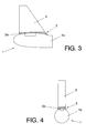
- This rear part comprises a tail cone constituting a first piece 1 whose configuration can be modified in order to conduct different tests in the aerodynamic tunnel.
- the vertical stabilizer constituting a second piece 2 whose structure should be coupled to the different configurations that the tail cone 1 can adopt, is joined to the tail cone 1, which requires modifying the junction area or coupling part of the horizontal stabilizer 2 to the tail cone 1.
- what is done in the state of the art is manufacturing a new vertical stabilizer 2 for each new design of the tail cone 1 that is made, which is avoided by means the invention.
- the method of the invention envisages designing and manufacturing the first piece 1 with a first configuration 1a corresponding to that which is desired to be tested in the aerodynamic tunnel, and then designing and manufacturing the vertical stabilizer 2 with a fixed configuration, as shown in the figures, so that this fixed configuration is valid for any possible configuration that the tail cone may adopt, and thus lacks the coupling part to the tail cone 1, so that the fixed configuration of the vertical stabilizer 2 is the same for any configuration of the tail cone 1, what avoids manufacturing it with each new configuration of the tail cone 1.
- a third piece 3 is required to be designed and manufactured with a first configuration 3a, corresponding to the coupling part between the first configuration 1a of the tail cone 1 and the fixed configuration of the vertical stabilizer 2.
- the third piece is constituted by different additional parts which, when joined to the horizontal stabilizer 2, provide the first coupling configuration 3a allowing the joint between the tail cone 1 and the vertical stabilizer 2.
- Reference 2a represents the shovel that is conventionally used to joint the vertical stabilizer 2 and the tail cone 1.
- Said reference 2a represents the part of the fixed configuration of said shovel, since said shovel can further include additional parts constituting the first configuration 3a of the third piece 3 according to the needs required in the junction area between the vertical stabilizer 2 and the tail cone 1.
- This configuration allows performing an optimum design of the fixed part 2a of the shovel, what reduces the stress supported by the shovel and which is valid for each and every one of the different configurations that the tail cone 1 may present, since said fixed part 2a of the shovel will be then complemented with the additional parts required to complete the shovel and that form part of the third piece corresponding to the coupling part between the tail cone 1 and the vertical stabilizer 2.
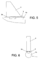
- the case wherein the tail cone 1 has been modified so that a second configuration 1b of the tail cone 1 is obtained is shown in figures 5 and 6 .
- the fixed configuration of the vertical stabilizer 2 remains the same as for the previous example, whereby the junction area of the vertical stabilizer 2 to the second configuration 1b of the tail cone 1 varies. Consequently, in this case the third piece 3 is constituted by additional second parts that, as in the previous case, when joined, provide a second coupling configuration 3b between the second configuration 1b of the tail cone 1 and the vertical stabilizer 2.
- the third piece 3a is constituted by additional second parts which, when joined, provide the second coupling configuration between the second configuration of the tail cone 1a and the vertical stabilizer 2.
Landscapes
- Engineering & Computer Science (AREA)
- Physics & Mathematics (AREA)
- General Physics & Mathematics (AREA)
- Human Computer Interaction (AREA)
- Manufacturing & Machinery (AREA)
- Automation & Control Theory (AREA)
- Fluid Mechanics (AREA)
- Aerodynamic Tests, Hydrodynamic Tests, Wind Tunnels, And Water Tanks (AREA)
Applications Claiming Priority (1)
| Application Number | Priority Date | Filing Date | Title |
|---|---|---|---|
| ES200930704A ES2378794B1 (es) | 2009-09-18 | 2009-09-18 | Procedimiento de diseño y fabricación de piezas de maquetas de configuracion variable. |
Publications (1)
| Publication Number | Publication Date |
|---|---|
| EP2299343A2 true EP2299343A2 (de) | 2011-03-23 |
Family
ID=43357934
Family Applications (1)
| Application Number | Title | Priority Date | Filing Date |
|---|---|---|---|
| EP10380111A Withdrawn EP2299343A2 (de) | 2009-09-18 | 2010-08-26 | Verfahren für Entwurf und Herstellung von Modellteilen variabler Konfiguration |
Country Status (3)
| Country | Link |
|---|---|
| US (1) | US20110119886A1 (de) |
| EP (1) | EP2299343A2 (de) |
| ES (1) | ES2378794B1 (de) |
Families Citing this family (1)
| Publication number | Priority date | Publication date | Assignee | Title |
|---|---|---|---|---|
| US10431833B2 (en) | 2012-03-01 | 2019-10-01 | Bloom Energy Corporation | Coatings for metal interconnects to reduce SOFC degradation |
Family Cites Families (9)
| Publication number | Priority date | Publication date | Assignee | Title |
|---|---|---|---|---|
| US4148450A (en) * | 1975-05-06 | 1979-04-10 | Hermann Neuhierl | Model aircraft construction |
| US4417708A (en) * | 1982-05-12 | 1983-11-29 | Grumman Aerospace Corporation | Interchangeable wing aircraft |
| US4736910A (en) * | 1984-08-10 | 1988-04-12 | Flight Concepts Limited Partnership | Aircraft with interchangeable fuselage |
| US4698041A (en) * | 1985-08-05 | 1987-10-06 | Madhava Dasa | Multiple configuration model aircraft |
| US5007875A (en) * | 1987-10-02 | 1991-04-16 | Madhava Dasa | Multiple configuration model aircraft |
| GB2328918A (en) * | 1997-09-04 | 1999-03-10 | British Aerospace | Selecting modules to produce aircraft variants |
| US6568632B2 (en) * | 2001-04-04 | 2003-05-27 | The Boeing Company | Variable size blended wing body aircraft |
| ES2291093B1 (es) * | 2005-10-31 | 2008-12-16 | Airbus España, S.L. | Sistema para transmitir presiones entre una pieza desmontable y una pieza fija de una maqueta dispuesta en un tunel aerodinamico. |
| US7966872B2 (en) * | 2008-07-23 | 2011-06-28 | The Boeing Company | In-flight testing kits and methods for evaluating proposed aerodynamic structures for aircraft |
-
2009
- 2009-09-18 ES ES200930704A patent/ES2378794B1/es not_active Expired - Fee Related
-
2010
- 2010-08-26 EP EP10380111A patent/EP2299343A2/de not_active Withdrawn
- 2010-09-08 US US12/877,144 patent/US20110119886A1/en not_active Abandoned
Non-Patent Citations (1)
| Title |
|---|
| None |
Also Published As
| Publication number | Publication date |
|---|---|
| US20110119886A1 (en) | 2011-05-26 |
| ES2378794A1 (es) | 2012-04-18 |
| ES2378794B1 (es) | 2013-01-29 |
Similar Documents
| Publication | Publication Date | Title |
|---|---|---|
| KR102669678B1 (ko) | 유연체들을 시밍하기 위한 시스템들 및 방법들 | |
| Cavagna et al. | NeoCASS: an integrated tool for structural sizing, aeroelastic analysis and MDO at conceptual design level | |
| US7966872B2 (en) | In-flight testing kits and methods for evaluating proposed aerodynamic structures for aircraft | |
| CN109918694B (zh) | 一种基于离散化载荷模型的飞机载荷计算方法 | |
| EP3023765A2 (de) | Kombinierte belastung in verbundstoffmaterialien | |
| CN105579344B (zh) | 将预装配的动力装置和挂架总成附接到飞机的方法 | |
| JP2011504842A (ja) | 航空機の2つの胴体部分間の接続を準備する方法 | |
| CN108152040B (zh) | 一种航空发动机空气管路流量校准的方法 | |
| CN110160758B (zh) | 开裂式舵系统地面刚度试验方法 | |
| CN105092191A (zh) | 一种直升机复合材料桨叶疲劳试验系统及方法 | |
| CN107766612B (zh) | 一种连接翼结构形式机翼载荷测量方法 | |
| KR20140140279A (ko) | 회전익 항공기 미부 공력진동 예측시스템 및 그 제어방법 | |
| CN105258915A (zh) | 一种高速风洞中变侧滑角叶片腹撑装置 | |
| CN107466285A (zh) | 飞机组装期间对飞机结构构件上的负载的模拟 | |
| CN106557599B (zh) | 一种空间力系载荷谱编制方法 | |
| CN110543694A (zh) | 一种航空发动机辅助吊挂拉杆振动计算方法 | |
| CN108645592A (zh) | 一种用于跨声速风洞双机身布局飞行器的双天平双叶片支撑装置 | |
| CN113626892B (zh) | 共形曲面天线罩高精度三维模型重建方法 | |
| US20110119886A1 (en) | Method for designing and manufacturing model pieces of variable configuration | |
| CN208254767U (zh) | 一种用于跨声速风洞双机身布局飞行器的双天平双叶片支撑装置 | |
| US20150160100A1 (en) | Method and device for testing a system of actuating a movable structure of a thrust reverser | |
| CN105335579A (zh) | 一种大展弦比飞机飞行载荷设计方法 | |
| Acero et al. | Morphing technology for advanced future commercial aircrafts | |
| CN105335574A (zh) | 一种飞机内埋舱舱门载荷设计方法 | |
| CN104477404A (zh) | 一种大载荷下机身主承力结构件的地面验证方法 |
Legal Events
| Date | Code | Title | Description |
|---|---|---|---|
| PUAI | Public reference made under article 153(3) epc to a published international application that has entered the european phase |
Free format text: ORIGINAL CODE: 0009012 |
|
| AK | Designated contracting states |
Kind code of ref document: A2 Designated state(s): AL AT BE BG CH CY CZ DE DK EE ES FI FR GB GR HR HU IE IS IT LI LT LU LV MC MK MT NL NO PL PT RO SE SI SK SM TR |
|
| AX | Request for extension of the european patent |
Extension state: BA ME RS |
|
| RIN1 | Information on inventor provided before grant (corrected) |
Inventor name: ROMERO CHECA, EDUARDO Inventor name: DE MARCOS SERRANO, ANGEL Inventor name: ALVAREZ GONZALEZ, JOSE JULIAN |
|
| STAA | Information on the status of an ep patent application or granted ep patent |
Free format text: STATUS: THE APPLICATION HAS BEEN PUBLISHED |
|
| STAA | Information on the status of an ep patent application or granted ep patent |
Free format text: STATUS: THE APPLICATION IS DEEMED TO BE WITHDRAWN |
|
| 18D | Application deemed to be withdrawn |
Effective date: 20180301 |