EP2299234A1 - Tracking type laser gauge interferometer - Google Patents
Tracking type laser gauge interferometer Download PDFInfo
- Publication number
- EP2299234A1 EP2299234A1 EP10177473A EP10177473A EP2299234A1 EP 2299234 A1 EP2299234 A1 EP 2299234A1 EP 10177473 A EP10177473 A EP 10177473A EP 10177473 A EP10177473 A EP 10177473A EP 2299234 A1 EP2299234 A1 EP 2299234A1
- Authority
- EP
- European Patent Office
- Prior art keywords
- light
- rotating mechanism
- recursive reflector
- main body
- body part
- Prior art date
- Legal status (The legal status is an assumption and is not a legal conclusion. Google has not performed a legal analysis and makes no representation as to the accuracy of the status listed.)
- Granted
Links
- 238000005259 measurement Methods 0.000 claims abstract description 43
- 230000003287 optical effect Effects 0.000 description 19
- 241000282326 Felis catus Species 0.000 description 9
- 238000010586 diagram Methods 0.000 description 6
- 238000006073 displacement reaction Methods 0.000 description 4
- 238000001514 detection method Methods 0.000 description 3
- 230000002452 interceptive effect Effects 0.000 description 3
- 230000010287 polarization Effects 0.000 description 3
- 238000012986 modification Methods 0.000 description 1
- 230000004048 modification Effects 0.000 description 1
Images


Classifications
-
- G—PHYSICS
- G01—MEASURING; TESTING
- G01S—RADIO DIRECTION-FINDING; RADIO NAVIGATION; DETERMINING DISTANCE OR VELOCITY BY USE OF RADIO WAVES; LOCATING OR PRESENCE-DETECTING BY USE OF THE REFLECTION OR RERADIATION OF RADIO WAVES; ANALOGOUS ARRANGEMENTS USING OTHER WAVES
- G01S7/00—Details of systems according to groups G01S13/00, G01S15/00, G01S17/00
- G01S7/48—Details of systems according to groups G01S13/00, G01S15/00, G01S17/00 of systems according to group G01S17/00
- G01S7/481—Constructional features, e.g. arrangements of optical elements
- G01S7/4811—Constructional features, e.g. arrangements of optical elements common to transmitter and receiver
-
- G—PHYSICS
- G01—MEASURING; TESTING
- G01S—RADIO DIRECTION-FINDING; RADIO NAVIGATION; DETERMINING DISTANCE OR VELOCITY BY USE OF RADIO WAVES; LOCATING OR PRESENCE-DETECTING BY USE OF THE REFLECTION OR RERADIATION OF RADIO WAVES; ANALOGOUS ARRANGEMENTS USING OTHER WAVES
- G01S17/00—Systems using the reflection or reradiation of electromagnetic waves other than radio waves, e.g. lidar systems
- G01S17/02—Systems using the reflection of electromagnetic waves other than radio waves
- G01S17/06—Systems determining position data of a target
- G01S17/42—Simultaneous measurement of distance and other co-ordinates
-
- G—PHYSICS
- G01—MEASURING; TESTING
- G01S—RADIO DIRECTION-FINDING; RADIO NAVIGATION; DETERMINING DISTANCE OR VELOCITY BY USE OF RADIO WAVES; LOCATING OR PRESENCE-DETECTING BY USE OF THE REFLECTION OR RERADIATION OF RADIO WAVES; ANALOGOUS ARRANGEMENTS USING OTHER WAVES
- G01S17/00—Systems using the reflection or reradiation of electromagnetic waves other than radio waves, e.g. lidar systems
- G01S17/66—Tracking systems using electromagnetic waves other than radio waves
Definitions
- the present invention relates to a tracking type laser gauge interferometer.
- a tracking type laser gauge interferometer which is comprised of a first recursive reflector provided at a predetermined position to reflect light parallel to incident light; a second recursive reflector attached to a measurement object; a main body part for guiding to the first recursive reflector light emitted from a laser light source and making emergent the light reflected at the first recursive reflector; a rotating mechanism for rotating the main body part about the first recursive reflector; and a control unit for controlling the rotating mechanism on the basis of the light emergent from the main body part and reflected at the second recursive reflector, so as to measure the distance between the recursive reflectors while tracking the second recursive reflector (e.g., refer to JP-A-7-120213 ).
- the tracking type laser interferometer (tracking type laser gauge interferometer) described in JP-A-7-120213 has two cat's eyes (first recursive reflector and second recursive reflector), a rotating part (main body part), a supporting frame serving as the rotating mechanism, two motors, and the control unit, and measures the distance between the cat's eyes while tracking the cat' s eye serving as the second recursive reflector.
- the tracking type laser interferometer described in JP-A-7-120213 in the state in which the rotating mechanism is not rotating about the cat's eye serving as the first recursive reflector, the rotating portion is rotated by using as axes two axes which are perpendicular to the traveling direction of the light incident on this cat' s eye. Accordingly, the tracking type laser interferometer described in JP-A-7-120213 is capable of calculating the position of a moving body on the basis of the rotational angle of the rotating mechanism and the distance between the cat's eyes.
- the tracking type laser interferometer described in JP-A-7-120213 has a problem in that it is unable to properly acquire the rotational angle of the rotating mechanism, and is hence unable to properly calculate the position of the moving object.
- An object of the present invention is to provide a tracking type laser gauge interferometer which is capable of properly acquiring the rotational angle of the rotating mechanism.
- a tracking type laser gauge interferometer including: a first recursive reflector provided at a predetermined position, the first recursive reflector being configured to reflect light parallel to incident light; a second recursive reflector attached to a measurement object; a main body part configured to guide light emitted from a laser light source to the first recursive reflector and make emergent the light reflected at the first recursive reflector; a rotating mechanism configured to rotate the main body part about the first recursive reflector; and a control unit configured to control the rotating mechanism on the basis of the light emergent from the main body part and reflected at the second recursive reflector, so as to measure the distance between the recursive reflectors while tracking the second recursive reflector, wherein: the main body part includes a light receiving element configured to receive the light reflected at the first recursive reflector and detect a position of the received light; and the control device includes: an angle acquisition unit configured to
- a recursive reflector such as a spherical body having a refractive index 2, a retro-reflector, a cat's eye, causes the light incident toward its center to be reflected through the same optical path as that of the incident light, and causes the light incident in an offset manner from the center to be reflected through a different route from that of the incident light.
- the center of the recursive reflector differs depending on the configuration of the recursive reflector, and in the case of, for example, the spherical body having a refractive index 2, the center of the recursive reflector is the center of the spherical body.
- the rotating mechanism causes its main body part to rotate about the center of the first recursive reflector
- the light incident on the first recursive reflector is made incident toward the center of the first recursive reflector irrespective of the rotation of the main body part, and is reflected through the same optical path as that of the incident light.
- the light incident on the first recursive reflector is made incident in such a manner as to be offset from the center of the recursive reflector, and is reflected through a different optical path from that of the incident light.
- the main body part has a light receiving element for receiving the light reflected at the first recursive reflector and detecting the position of the received light
- the position of the light detected by the light receiving element does not undergo displacement in cases where motion errors do not occur in the rotating mechanism, and undergoes displacement in cases where motion errors occur in the rotating mechanism.
- the control device since the control device has the angle acquisition unit for acquiring the rotational angle of the rotating mechanism and the correction unit for correcting the motion error of the rotating mechanism acquired by the angle acquisition unit, it is possible to properly acquire the rotational angle of the rotating mechanism.
- the control unit may include a position calculation unit configured to calculate a position of the second recursive reflector on the basis of the motion error of the rotating mechanism corrected by the angle correcting unit and a distance between the recursive reflectors.
- control device since the control device has the position calculation unit for calculating the position of the second recursive reflector on the basis of the rotational angle of the rotating mechanism corrected by the correction unit, it is possible to properly calculate the position of the measurement object.
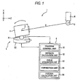
- Fig. 1 is a schematic diagram illustrating a tracking type laser gauge interferometer 1 in accordance with an embodiment of the present invention.
- the tracking type laser gauge interferometer 1 is comprised of a measurement reference gage 2 serving a first recursive reflector provided at a predetermined position to reflect light parallel to incident light; a target 3 serving as a second recursive reflector attached to a measurement object W; a main body part 4 for guiding to the measurement reference gauge 2 light emitted from a laser light source LS (see Fig.
- This tracking type laser gauge interferometer 1 measures a distance D between the measurement reference gauge 2 and the target 3 while tracking the target 3. It should be noted that, in Fig. 1 , it is assumed that in the state in which the rotating mechanism 5 is not rotating about the cat's eye serving as the first recursive reflector, the traveling direction (rightward direction in Fig. 1 ) of the light emergent from the main body part 4 is set as a +Z-axis direction, and two axes perpendicular to this Z-axis are respectively set as an X-axis and a Y-axis. The same also applies to the drawings that follow.
- Fig. 2 is a diagram illustrating an example of each of the recursive reflectors which are used as the measurement reference gauge 2 and the target 3. It should be noted that, in Fig. 2 , the light incident on the recursive reflector and the light reflected at the recursive reflector are indicated by broken lines with arrows, and these arrows indicate the traveling direction of the light. As the measurement reference gauge 2 and the target 3, a spherical body having a refractive index 2 is used as the recursive reflector, as shown in Fig. 2 . Each of the measurement reference gauge 2 and the target 3 causes the light incident toward a center O to be reflected through the same optical path (two-dot chain line in Fig. 2 ) as that of the incident light, and causes the light incident in an offset manner from the center to be reflected through a different route (broken line in Fig. 2 ) from that of the incident light.
- the measurement reference gauge 2 and the target 3 causes the light incident toward a center O to be
- Fig. 3 is a schematic diagram illustrating an optical system 7 disposed in the main body part 4. It should be noted that, in Fig. 3 , the optical axis of the tracking type laser gauge interferometer 1 including the measurement reference gauge 2, the target, 3, and the optical system 7 is indicated by a two-dot chain line. As shown in Fig. 3 , the main body part 4 has the optical system 7 which is disposed between the measurement reference gauge 2 and the target 3.
- the optical system 7 has an optical length measuring system 8 for guiding to the measurement reference gauge 2 the light emitted from the laser light source LS and for measuring the distance D between the measurement reference gauge 2 and the target 3 as well as an optical detection system 9 for detecting the light reflected at the measurement reference gauge 2 and the light emergent from the main body part 4 and reflected at the target 3.
- the optical length measuring system 8 has a polarizing beam splitter 81 disposed in a latter stage of the optical path of the laser light source LS so as to split the light emitted from the laser light source LS; a quarter-wave plate 82 disposed between the polarizing beam splitter 81 and the measurement reference gauge 2 to retard the phase of the incident light by 90°; a quarter-wave plate 83 disposed between the polarizing beam splitter 81 and the optical detection system 9; and a polarizing plate 84 provided on a surface of the polarizing beam splitter 81 opposite to the laser light source LS side surface thereof.
- the polarizing beam splitter 81 has a polarizing splitting film 81A which allows p-polarized light to be transmitted therethrough and reflects s-polarized light.
- the polarizing plate 84 transmits therethrough only the light having a predetermined direction of polarization, and is disposed so as to allow the polarizing splitting film 81A to transmit the p-polarized and s-polarized light therethrough.
- the optical detection system 9 has a beam splitter 91 disposed between the optical length measuring system 8 and the target 3, a two-dimensional position sensitive detector (PSD) 92 disposed on the opposite side to the laser light source LS side, and a two-dimensional PSD 93 disposed on the laser light source LS side.
- the beam splitter 91 reflects part of the incident light at its interface 91A and allows other portion to be transmitted therethrough.
- the two-dimensional PSDs 92 and 93 detect the position of the light which they receive, and the two-dimensional PSD 92 is disposed at a position for receiving the light incident on the beam splitter 91 from the optical length measuring system 8 side and reflected at the interface 91A, while the two-dimensional PSD 93 is disposed at a position for receiving the light incident on the beam splitter 91 from the target 3 side and reflected at the interface 91A.
- the light emitted from the laser light source LS is incident on the polarizing beam splitter 81.
- the s-polarized light is reflected at the polarizing splitting film 81A and is incident on the measurement reference gauge 2 (hereafter, this light will be referred to as measurement light).
- the p-polarized light is transmitted through the polarizing splitting film 81A and is incident on the polarizing plate 84 (hereafter, this light will be referred to as reference light).
- the measurement light incident on the measurement reference gauge 2 is reflected at the measurement reference gauge 2 and is again made incident on the polarizing beam splitter 81.
- the measurement light since the measurement light has passed through the quarter-wave plate 82 twice, its direction of polarization is rotated 90°, so that it becomes p-polarized light with respect to the polarizing splitting film 81A. Accordingly, the measurement light incident again on the polarizing beam splitter 81 is transmitted through the polarizing splitting film 81A and is incident on the beam splitter 91.
- Part of the measurement light incident on the beam splitter 91 is reflected at the interface 91A and is received by the two-dimensional PSD 92. Meanwhile, other part of the light is transmitted through the interface 91A and is made emergent from the main body part 4.
- a light receiving element is constituted by the two-dimensional PSD 92.
- the measurement light emergent from the main body part 4 is reflected at the target 3, and is again made incident on the beam splitter 91.
- Part of the measurement light incident again on the beam splitter 91 is reflected at the interface 91A and is received by the two-dimensional PSD 93. Meanwhile, other part of the light is transmitted through the interface 91A and is again made incident on the polarizing beam splitter 81.
- the measurement light since the measurement light has passed through the quarter-wave plate 83 twice, its direction of polarization is rotated 90°, so that it becomes s-polarized light with respect to the polarizing splitting film 81A.
- the measurement light incident again on the polarizing beam splitter 81 is reflected at the polarizing splitting film 81A and is incident on the polarizing plate 84.
- the measurement light and the reference light incident on the polarizing plate 84 then form interfering light, which is made emergent from the polarizing plate 84. It should be noted that the interfering light emergent from the polarizing plate 84 is received by a light receiving device (not shown).
- the rotating mechanism 5 has a supporting member 51 which has as its rotational axis (hereafter, a y-axis) an axis passing through the center O of the measurement reference gauge 2 (see Fig. 3 ) and parallel to the Y-axis, and which rotatably supports the main body part 4, as well as a table 52 which has as its rotational axis (hereafter, an x-axis) an axis passing through the center O of the measurement reference gauge 2 and parallel to the X-axis, and which rotatably supports the supporting member 51.
- the rotating mechanism 5 has an x-axis driving unit for rotating the supporting member 51 about the x-axis (arrow A in Fig.
- the rotating mechanism 5 has a sensor for detecting the rotational angle of the supporting member 51 about the x-axis and the rotational angle of the main body part 4 about the y-axis. Namely, in the state in which the rotating mechanism 5 is not rotating about the center O of the measurement reference gauge 2, the rotating mechanism 5 rotates the main body part 4 by using as its rotational axes two axes which are perpendicular to the traveling direction (-z-axis direction) of the light incident on the measurement reference gauge 2.
- the control device 6 is configured by including a central processing unit (CPU), memory, and the like to control the tracking type laser gauge interferometer 1, and includes a tracking control unit 61, a distance calculation unit 62, an angle acquisition unit 63, an correction unit 64, and a position calculation unit 65.
- the tracking control unit 61 tracks the target 3 by controlling the rotating mechanism 5 on the basis of the light reflected from the target 3. Specifically, since the target 3 is a recursive reflector, when the target 3 moves in conjunction with the movement of the measurement object W, the position of the light reflected at the target 3 and detected by the two-dimensional PSD 93 undergoes displacement. Accordingly, by controlling the rotating mechanism 5 on the basis of the position of the light detected by the two-dimensional PSD 93, the tracking control unit 61 is able to control the traveling direction of the light emergent from the main body part 4 to thereby track the target 3.
- CPU central processing unit
- the distance calculation unit 62 calculates the distance D between the measurement reference gauge 2 and the target 3 on the basis of the interfering light emergent from the polarizing plate 84 and received by the aforementioned light receiving device.
- the angle acquisition unit 63 acquires the rotational angles of the main body part 4 about the x- and y-axes, i.e., the rotational angles of the rotating mechanism 5, through the sensor of the rotating mechanism 5.
- the correction unit 64 corrects the motion errors of the rotating mechanism 5 acquired by the angle acquisition unit 63, on the basis of the position of the light detected by the two-dimensional PSD 92. Specifically, since the measurement reference gauge 2 is a recursive reflector, when motion errors occur in the rotating mechanism 5, the position of the light detected by the two-dimensional PSD 92 undergoes displacement. Accordingly, the correction unit 64 is able to correct the motion errors of the rotating mechanism 5 acquired by the angle acquisition unit 63, on the basis of the position of the light detected by the two-dimensional PSD 92.
- the position calculation unit 65 calculates the position of the target 3 on the basis of the rotational angles of the rotating mechanism 5 corrected by the correction unit 64 and the distance D between the measurement reference gauge 2 and the target 3 calculated by the distance calculation unit 62.
- control device 6 since the control device 6 has the angle acquisition unit 63 for acquiring the rotational angles of the rotating mechanism 5 and the correction unit 64 for correcting the motion errors of the rotating mechanism 5 acquired by the angle acquisition unit 63, it is possible to properly acquire the rotational angles of the rotating mechanism 5. Further, since the control device 6 has the position calculation unit 65 for calculating the position of the target 3 on the basis of the rotational angles of the rotating mechanism 5 corrected by the correction unit 64, it is possible to properly calculate the position of the measurement object W.
- the control device 6 has the position calculation unit 65 for calculating the position of the target 3.
- the control device may not have the position calculation unit.
- the control device is sufficient if it has the angle acquisition unit and the correction unit.
- the light receiving element is constituted by the two-dimensional PSD 92.
- the light receiving element may be constituted by a 4-split photodiode or the like. In short, the light receiving element is sufficient if it is able to detect the position of the received light.
- the rotating mechanism 5 is arranged such that its main body part 4 is rotated about two rotational axes, i.e., the x- and y-axes.
- the rotating mechanism 5 may be arranged such that its main body part is rotated about one rotational axis or three or more rotational axes. In short, the rotating mechanism is sufficient if its main body part is rotated about the first recursive reflector.
- the present invention can be suitably used as the tracking type laser gauge interferometer.
Landscapes
- Physics & Mathematics (AREA)
- Engineering & Computer Science (AREA)
- Electromagnetism (AREA)
- Computer Networks & Wireless Communication (AREA)
- General Physics & Mathematics (AREA)
- Radar, Positioning & Navigation (AREA)
- Remote Sensing (AREA)
- Instruments For Measurement Of Length By Optical Means (AREA)
- Length Measuring Devices By Optical Means (AREA)
- Optical Radar Systems And Details Thereof (AREA)
Abstract
Description
- The present invention relates to a tracking type laser gauge interferometer.
- Conventionally, a tracking type laser gauge interferometer is known which is comprised of a first recursive reflector provided at a predetermined position to reflect light parallel to incident light; a second recursive reflector attached to a measurement object; a main body part for guiding to the first recursive reflector light emitted from a laser light source and making emergent the light reflected at the first recursive reflector; a rotating mechanism for rotating the main body part about the first recursive reflector; and a control unit for controlling the rotating mechanism on the basis of the light emergent from the main body part and reflected at the second recursive reflector, so as to measure the distance between the recursive reflectors while tracking the second recursive reflector (e.g., refer to
JP-A-7-120213 - The tracking type laser interferometer (tracking type laser gauge interferometer) described in
JP-A-7-120213 JP-A-7-120213 JP-A-7-120213 - However, since motion errors occur in the rotating mechanism, the tracking type laser interferometer described in
JP-A-7-120213 - An object of the present invention is to provide a tracking type laser gauge interferometer which is capable of properly acquiring the rotational angle of the rotating mechanism.
- According to an aspect of the invention, there is provided a tracking type laser gauge interferometer including: a first recursive reflector provided at a predetermined position, the first recursive reflector being configured to reflect light parallel to incident light; a second recursive reflector attached to a measurement object; a main body part configured to guide light emitted from a laser light source to the first recursive reflector and make emergent the light reflected at the first recursive reflector; a rotating mechanism configured to rotate the main body part about the first recursive reflector; and a control unit configured to control the rotating mechanism on the basis of the light emergent from the main body part and reflected at the second recursive reflector, so as to measure the distance between the recursive reflectors while tracking the second recursive reflector, wherein: the main body part includes a light receiving element configured to receive the light reflected at the first recursive reflector and detect a position of the received light; and the control device includes: an angle acquisition unit configured to acquire a rotational angle of the rotating mechanism; and an correction unit configured to correct a motion error of the rotating mechanism.
- Here, a recursive reflector, such as a spherical body having a
refractive index 2, a retro-reflector, a cat's eye, causes the light incident toward its center to be reflected through the same optical path as that of the incident light, and causes the light incident in an offset manner from the center to be reflected through a different route from that of the incident light. It should be noted that the center of the recursive reflector differs depending on the configuration of the recursive reflector, and in the case of, for example, the spherical body having arefractive index 2, the center of the recursive reflector is the center of the spherical body. - In addition, since the rotating mechanism causes its main body part to rotate about the center of the first recursive reflector, in cases where motion errors do not occur in the rotating mechanism, the light incident on the first recursive reflector is made incident toward the center of the first recursive reflector irrespective of the rotation of the main body part, and is reflected through the same optical path as that of the incident light. However, in cases where motion errors occur in the rotating mechanism, the light incident on the first recursive reflector is made incident in such a manner as to be offset from the center of the recursive reflector, and is reflected through a different optical path from that of the incident light.
- Therefore, according to the present invention, since the main body part has a light receiving element for receiving the light reflected at the first recursive reflector and detecting the position of the received light, the position of the light detected by the light receiving element does not undergo displacement in cases where motion errors do not occur in the rotating mechanism, and undergoes displacement in cases where motion errors occur in the rotating mechanism. Further, since the control device has the angle acquisition unit for acquiring the rotational angle of the rotating mechanism and the correction unit for correcting the motion error of the rotating mechanism acquired by the angle acquisition unit, it is possible to properly acquire the rotational angle of the rotating mechanism.
- The control unit may include a position calculation unit configured to calculate a position of the second recursive reflector on the basis of the motion error of the rotating mechanism corrected by the angle correcting unit and a distance between the recursive reflectors.
- According to the above-described configuration, since the control device has the position calculation unit for calculating the position of the second recursive reflector on the basis of the rotational angle of the rotating mechanism corrected by the correction unit, it is possible to properly calculate the position of the measurement object.
- The present invention will become more fully understood from the detailed description given hereinbelow and the accompanying drawing which is given by way of illustration only, and thus is not limitative of the present invention and wherein:
-
Fig. 1 is a schematic diagram illustrating a tracking type laser gauge interferometer in accordance with an embodiment of the present invention; -
Fig. 2 is a diagram illustrating an example of each of the recursive reflectors which are used as a measurement reference gauge and a target in the embodiment; and -
Fig. 3 is a schematic diagram illustrating an optical system disposed in a main body part in the embodiment. - Hereafter, a description will be given of an embodiment of the present invention with reference to the accompanying drawings.
Fig. 1 is a schematic diagram illustrating a tracking typelaser gauge interferometer 1 in accordance with an embodiment of the present invention. As shown inFig. 1 , the tracking typelaser gauge interferometer 1 is comprised of ameasurement reference gage 2 serving a first recursive reflector provided at a predetermined position to reflect light parallel to incident light; atarget 3 serving as a second recursive reflector attached to a measurement object W; amain body part 4 for guiding to themeasurement reference gauge 2 light emitted from a laser light source LS (seeFig. 3 ) and making emergent the light reflected at themeasurement reference gauge 2; arotating mechanism 5 for rotating themain body part 4 about themeasurement reference gauge 2; and a control device 6 for controlling therotating mechanism 5 on the basis of the light emergent from themain body part 4 and reflected at thetarget 3. - This tracking type
laser gauge interferometer 1 measures a distance D between themeasurement reference gauge 2 and thetarget 3 while tracking thetarget 3. It should be noted that, inFig. 1 , it is assumed that in the state in which therotating mechanism 5 is not rotating about the cat's eye serving as the first recursive reflector, the traveling direction (rightward direction inFig. 1 ) of the light emergent from themain body part 4 is set as a +Z-axis direction, and two axes perpendicular to this Z-axis are respectively set as an X-axis and a Y-axis. The same also applies to the drawings that follow. -
Fig. 2 is a diagram illustrating an example of each of the recursive reflectors which are used as themeasurement reference gauge 2 and thetarget 3. It should be noted that, inFig. 2 , the light incident on the recursive reflector and the light reflected at the recursive reflector are indicated by broken lines with arrows, and these arrows indicate the traveling direction of the light. As themeasurement reference gauge 2 and thetarget 3, a spherical body having arefractive index 2 is used as the recursive reflector, as shown inFig. 2 . Each of themeasurement reference gauge 2 and thetarget 3 causes the light incident toward a center O to be reflected through the same optical path (two-dot chain line inFig. 2 ) as that of the incident light, and causes the light incident in an offset manner from the center to be reflected through a different route (broken line inFig. 2 ) from that of the incident light. -
Fig. 3 is a schematic diagram illustrating anoptical system 7 disposed in themain body part 4. It should be noted that, inFig. 3 , the optical axis of the tracking typelaser gauge interferometer 1 including themeasurement reference gauge 2, the target, 3, and theoptical system 7 is indicated by a two-dot chain line. As shown inFig. 3 , themain body part 4 has theoptical system 7 which is disposed between themeasurement reference gauge 2 and thetarget 3. Theoptical system 7 has an optical length measuring system 8 for guiding to themeasurement reference gauge 2 the light emitted from the laser light source LS and for measuring the distance D between themeasurement reference gauge 2 and thetarget 3 as well as anoptical detection system 9 for detecting the light reflected at themeasurement reference gauge 2 and the light emergent from themain body part 4 and reflected at thetarget 3. - The optical length measuring system 8 has a polarizing
beam splitter 81 disposed in a latter stage of the optical path of the laser light source LS so as to split the light emitted from the laser light source LS; a quarter-wave plate 82 disposed between the polarizingbeam splitter 81 and themeasurement reference gauge 2 to retard the phase of the incident light by 90°; a quarter-wave plate 83 disposed between the polarizingbeam splitter 81 and theoptical detection system 9; and a polarizingplate 84 provided on a surface of the polarizingbeam splitter 81 opposite to the laser light source LS side surface thereof. The polarizingbeam splitter 81 has a polarizing splittingfilm 81A which allows p-polarized light to be transmitted therethrough and reflects s-polarized light. The polarizingplate 84 transmits therethrough only the light having a predetermined direction of polarization, and is disposed so as to allow the polarizing splittingfilm 81A to transmit the p-polarized and s-polarized light therethrough. - The
optical detection system 9 has a beam splitter 91 disposed between the optical length measuring system 8 and thetarget 3, a two-dimensional position sensitive detector (PSD) 92 disposed on the opposite side to the laser light source LS side, and a two-dimensional PSD 93 disposed on the laser light source LS side. The beam splitter 91 reflects part of the incident light at itsinterface 91A and allows other portion to be transmitted therethrough. The two-dimensional PSDs 92 and 93 detect the position of the light which they receive, and the two-dimensional PSD 92 is disposed at a position for receiving the light incident on the beam splitter 91 from the optical length measuring system 8 side and reflected at theinterface 91A, while the two-dimensional PSD 93 is disposed at a position for receiving the light incident on the beam splitter 91 from thetarget 3 side and reflected at theinterface 91A. - Next, a description will be given of the optical path of the light in the tracking type
laser gauge interferometer 1. The light emitted from the laser light source LS is incident on the polarizingbeam splitter 81. Of the light incident on the polarizingbeam splitter 81, the s-polarized light is reflected at the polarizingsplitting film 81A and is incident on the measurement reference gauge 2 (hereafter, this light will be referred to as measurement light). Meanwhile, the p-polarized light is transmitted through the polarizing splittingfilm 81A and is incident on the polarizing plate 84 (hereafter, this light will be referred to as reference light). - The measurement light incident on the
measurement reference gauge 2 is reflected at themeasurement reference gauge 2 and is again made incident on the polarizingbeam splitter 81. At this time, since the measurement light has passed through the quarter-wave plate 82 twice, its direction of polarization is rotated 90°, so that it becomes p-polarized light with respect to the polarizing splittingfilm 81A. Accordingly, the measurement light incident again on the polarizingbeam splitter 81 is transmitted through the polarizing splittingfilm 81A and is incident on the beam splitter 91. Part of the measurement light incident on the beam splitter 91 is reflected at theinterface 91A and is received by the two-dimensional PSD 92. Meanwhile, other part of the light is transmitted through theinterface 91A and is made emergent from themain body part 4. Namely, in this embodiment, a light receiving element is constituted by the two-dimensional PSD 92. - The measurement light emergent from the
main body part 4 is reflected at thetarget 3, and is again made incident on the beam splitter 91. Part of the measurement light incident again on the beam splitter 91 is reflected at theinterface 91A and is received by the two-dimensional PSD 93. Meanwhile, other part of the light is transmitted through theinterface 91A and is again made incident on the polarizingbeam splitter 81. At this time, since the measurement light has passed through the quarter-wave plate 83 twice, its direction of polarization is rotated 90°, so that it becomes s-polarized light with respect to the polarizing splittingfilm 81A. Accordingly, the measurement light incident again on the polarizingbeam splitter 81 is reflected at the polarizingsplitting film 81A and is incident on the polarizingplate 84. The measurement light and the reference light incident on the polarizingplate 84 then form interfering light, which is made emergent from the polarizingplate 84. It should be noted that the interfering light emergent from the polarizingplate 84 is received by a light receiving device (not shown). - As shown in
Fig. 1 , therotating mechanism 5 has a supportingmember 51 which has as its rotational axis (hereafter, a y-axis) an axis passing through the center O of the measurement reference gauge 2 (seeFig. 3 ) and parallel to the Y-axis, and which rotatably supports themain body part 4, as well as a table 52 which has as its rotational axis (hereafter, an x-axis) an axis passing through the center O of themeasurement reference gauge 2 and parallel to the X-axis, and which rotatably supports the supportingmember 51. It should be noted that therotating mechanism 5 has an x-axis driving unit for rotating the supportingmember 51 about the x-axis (arrow A inFig. 3 ) and a y-axis driving unit for rotating themain body part 4 about the y-axis (arrow B inFig. 3 ) (neither are shown). These driving units respectively drive the supportingmember 51 and themain body part 4 under control by the control device 6. In addition, therotating mechanism 5 has a sensor for detecting the rotational angle of the supportingmember 51 about the x-axis and the rotational angle of themain body part 4 about the y-axis. Namely, in the state in which therotating mechanism 5 is not rotating about the center O of themeasurement reference gauge 2, therotating mechanism 5 rotates themain body part 4 by using as its rotational axes two axes which are perpendicular to the traveling direction (-z-axis direction) of the light incident on themeasurement reference gauge 2. - The control device 6 is configured by including a central processing unit (CPU), memory, and the like to control the tracking type
laser gauge interferometer 1, and includes atracking control unit 61, adistance calculation unit 62, anangle acquisition unit 63, ancorrection unit 64, and aposition calculation unit 65. Thetracking control unit 61 tracks thetarget 3 by controlling therotating mechanism 5 on the basis of the light reflected from thetarget 3. Specifically, since thetarget 3 is a recursive reflector, when thetarget 3 moves in conjunction with the movement of the measurement object W, the position of the light reflected at thetarget 3 and detected by the two-dimensional PSD 93 undergoes displacement. Accordingly, by controlling therotating mechanism 5 on the basis of the position of the light detected by the two-dimensional PSD 93, thetracking control unit 61 is able to control the traveling direction of the light emergent from themain body part 4 to thereby track thetarget 3. - The
distance calculation unit 62 calculates the distance D between themeasurement reference gauge 2 and thetarget 3 on the basis of the interfering light emergent from thepolarizing plate 84 and received by the aforementioned light receiving device. Theangle acquisition unit 63 acquires the rotational angles of themain body part 4 about the x- and y-axes, i.e., the rotational angles of therotating mechanism 5, through the sensor of therotating mechanism 5. - The
correction unit 64 corrects the motion errors of therotating mechanism 5 acquired by theangle acquisition unit 63, on the basis of the position of the light detected by the two-dimensional PSD 92. Specifically, since themeasurement reference gauge 2 is a recursive reflector, when motion errors occur in therotating mechanism 5, the position of the light detected by the two-dimensional PSD 92 undergoes displacement. Accordingly, thecorrection unit 64 is able to correct the motion errors of therotating mechanism 5 acquired by theangle acquisition unit 63, on the basis of the position of the light detected by the two-dimensional PSD 92. Theposition calculation unit 65 calculates the position of thetarget 3 on the basis of the rotational angles of therotating mechanism 5 corrected by thecorrection unit 64 and the distance D between themeasurement reference gauge 2 and thetarget 3 calculated by thedistance calculation unit 62. - According to the above-described embodiment, since the control device 6 has the
angle acquisition unit 63 for acquiring the rotational angles of therotating mechanism 5 and thecorrection unit 64 for correcting the motion errors of therotating mechanism 5 acquired by theangle acquisition unit 63, it is possible to properly acquire the rotational angles of therotating mechanism 5. Further, since the control device 6 has theposition calculation unit 65 for calculating the position of thetarget 3 on the basis of the rotational angles of therotating mechanism 5 corrected by thecorrection unit 64, it is possible to properly calculate the position of the measurement object W. - It should be noted that the present invention is not limited to the foregoing embodiment, and modifications, improvements, and the like within the scope in which the object of the present invention can be attained are included in the present invention. For example, in the above-described embodiment, the control device 6 has the
position calculation unit 65 for calculating the position of thetarget 3. However, the control device may not have the position calculation unit. In short, the control device is sufficient if it has the angle acquisition unit and the correction unit. In the above-described embodiment, the light receiving element is constituted by the two-dimensional PSD 92. In contrast, the light receiving element may be constituted by a 4-split photodiode or the like. In short, the light receiving element is sufficient if it is able to detect the position of the received light. - Although in the above-described embodiment spherical bodies having the
refractive index 2 are used as the first recursive reflector and the second recursive reflector, it is possible to use retro-reflectors, cat's eyes, or the like. In the above-describe embodiment, therotating mechanism 5 is arranged such that itsmain body part 4 is rotated about two rotational axes, i.e., the x- and y-axes. In contrast, therotating mechanism 5 may be arranged such that its main body part is rotated about one rotational axis or three or more rotational axes. In short, the rotating mechanism is sufficient if its main body part is rotated about the first recursive reflector. - The present invention can be suitably used as the tracking type laser gauge interferometer.
Claims (2)
- A tracking type laser gauge interferometer comprising:a first recursive reflector (2) provided at a predetermined position, the first recursive reflector (2) being configured to reflect light parallel to incident light;a second recursive reflector (3) attached to a measurement object (W);a main body part (4) configured to guide light emitted from a laser light source (LS) to the first recursive reflector (2) and make emergent the light reflected at the first recursive reflector (2);a rotating mechanism (5) configured to rotate the main body part (4) about the first recursive reflector (2); anda control means (6) configured to control the rotating mechanism (5) based on the light emergent from the main body part (4) and reflected at the second recursive reflector (3), so as to measure the distance between the recursive reflectors (2, 3) while tracking the second recursive reflector (3), wherein:the main body part (4) includes
a light receiving element (92) configured to receive the light reflected at the first recursive reflector (2) and detect a position of the received light; andthe control means (6) includes:an angle acquisition unit (63) configured to acquire a rotational angle of the rotating mechanism (5); andan correction unit (64) configured to correct a motion error of the rotating mechanism (5). - The tracking type laser gauge interferometer according to claim 1, wherein
the control means (6) includes a position calculation unit (65) configured to calculate a position of the second recursive reflector (3) based on the motion error of the rotating mechanism (5) corrected by the correcting unit (64) and a distance between the recursive reflectors (2, 3).
Applications Claiming Priority (1)
| Application Number | Priority Date | Filing Date | Title |
|---|---|---|---|
| JP2009216426A JP5364519B2 (en) | 2009-09-18 | 2009-09-18 | Tracking laser interferometer |
Publications (2)
| Publication Number | Publication Date |
|---|---|
| EP2299234A1 true EP2299234A1 (en) | 2011-03-23 |
| EP2299234B1 EP2299234B1 (en) | 2013-03-06 |
Family
ID=43242149
Family Applications (1)
| Application Number | Title | Priority Date | Filing Date |
|---|---|---|---|
| EP10177473A Not-in-force EP2299234B1 (en) | 2009-09-18 | 2010-09-17 | Tracking type laser gauge interferometer |
Country Status (3)
| Country | Link |
|---|---|
| US (1) | US8514405B2 (en) |
| EP (1) | EP2299234B1 (en) |
| JP (1) | JP5364519B2 (en) |
Cited By (1)
| Publication number | Priority date | Publication date | Assignee | Title |
|---|---|---|---|---|
| AT512768A1 (en) * | 2012-03-28 | 2013-10-15 | Riegl Laser Measurement Sys | Laser Scanner |
Families Citing this family (8)
| Publication number | Priority date | Publication date | Assignee | Title |
|---|---|---|---|---|
| US8803055B2 (en) * | 2009-01-09 | 2014-08-12 | Automated Precision Inc. | Volumetric error compensation system with laser tracker and active target |
| CN103292745B (en) * | 2013-05-07 | 2015-09-02 | 中国人民解放军军械工程学院 | The coaxality measuring mechanism of orifice in a kind of chorista |
| EP3287754B1 (en) * | 2015-04-20 | 2019-08-07 | Panasonic Intellectual Property Management Co., Ltd. | Vibration visualization element, vibration measurement system, and method for measuring vibration |
| TWI595252B (en) * | 2016-05-10 | 2017-08-11 | 財團法人工業技術研究院 | Distance measurement device and distance measuring method thereof |
| JP6799414B2 (en) * | 2016-08-10 | 2020-12-16 | 株式会社ミツトヨ | Feedback gain adjustment method and equipment for tracking laser interferometers |
| KR102101877B1 (en) * | 2019-10-18 | 2020-04-17 | (주)패스넷 | 3D Measuring Apparatus |
| US20250123095A1 (en) * | 2023-10-13 | 2025-04-17 | Zygo Corporation | Dynamic interferometer illuminator |
| WO2026069639A1 (en) * | 2024-09-30 | 2026-04-02 | 株式会社ニコン | Measurement system and machine tool |
Citations (5)
| Publication number | Priority date | Publication date | Assignee | Title |
|---|---|---|---|---|
| US4714339A (en) * | 1986-02-28 | 1987-12-22 | The United States Of America As Represented By The Secretary Of Commerce | Three and five axis laser tracking systems |
| JPH07120213A (en) | 1993-10-25 | 1995-05-12 | Agency Of Ind Science & Technol | Tracking laser interferometer |
| US20030020895A1 (en) * | 2001-04-10 | 2003-01-30 | Bridges Robert E. | Chopper-stabilized absolute distance meter |
| EP1750085A2 (en) * | 2005-07-26 | 2007-02-07 | Mitutoyo Corporation | Laser tracking interferometer |
| EP1895266A2 (en) * | 2006-09-04 | 2008-03-05 | Mitutoyo Corporation | Method for measuring length by laser interference tracking and apparatus therefore |
Family Cites Families (6)
| Publication number | Priority date | Publication date | Assignee | Title |
|---|---|---|---|---|
| JPS62106307A (en) * | 1985-11-02 | 1987-05-16 | Olympus Optical Co Ltd | Method and jig for positioning surface to be inspected of surface shape measuring machine |
| US7800758B1 (en) * | 1999-07-23 | 2010-09-21 | Faro Laser Trackers, Llc | Laser-based coordinate measuring device and laser-based method for measuring coordinates |
| JP4776454B2 (en) * | 2005-07-26 | 2011-09-21 | 株式会社ミツトヨ | Tracking laser interferometer |
| JP4776473B2 (en) * | 2006-08-25 | 2011-09-21 | 株式会社ミツトヨ | Optical axis deflection laser interferometer, its calibration method, correction method, and measurement method |
| JP5193490B2 (en) * | 2007-04-20 | 2013-05-08 | 株式会社ミツトヨ | Measuring method using tracking laser interferometer |
| JP5244339B2 (en) * | 2007-06-20 | 2013-07-24 | 株式会社ミツトヨ | Tracking laser interferometer and recovery method of tracking laser interferometer |
-
2009
- 2009-09-18 JP JP2009216426A patent/JP5364519B2/en not_active Expired - Fee Related
-
2010
- 2010-09-17 EP EP10177473A patent/EP2299234B1/en not_active Not-in-force
- 2010-09-17 US US12/884,700 patent/US8514405B2/en not_active Expired - Fee Related
Patent Citations (7)
| Publication number | Priority date | Publication date | Assignee | Title |
|---|---|---|---|---|
| US4714339A (en) * | 1986-02-28 | 1987-12-22 | The United States Of America As Represented By The Secretary Of Commerce | Three and five axis laser tracking systems |
| US4714339B1 (en) * | 1986-02-28 | 1997-03-18 | Us Army | Three and five axis laser tracking systems |
| US4714339B2 (en) * | 1986-02-28 | 2000-05-23 | Us Commerce | Three and five axis laser tracking systems |
| JPH07120213A (en) | 1993-10-25 | 1995-05-12 | Agency Of Ind Science & Technol | Tracking laser interferometer |
| US20030020895A1 (en) * | 2001-04-10 | 2003-01-30 | Bridges Robert E. | Chopper-stabilized absolute distance meter |
| EP1750085A2 (en) * | 2005-07-26 | 2007-02-07 | Mitutoyo Corporation | Laser tracking interferometer |
| EP1895266A2 (en) * | 2006-09-04 | 2008-03-05 | Mitutoyo Corporation | Method for measuring length by laser interference tracking and apparatus therefore |
Non-Patent Citations (1)
| Title |
|---|
| TEOH P L ET AL: "The measurement uncertainties in the laser interferometry-based sensing and tracking technique", MEASUREMENT, INSTITUTE OF MEASUREMENT AND CONTROL. LONDON, GB, vol. 32, no. 2, 1 September 2002 (2002-09-01), pages 135 - 150, XP004367624, ISSN: 0263-2241, DOI: 10.1016/S0263-2241(02)00006-4 * |
Cited By (2)
| Publication number | Priority date | Publication date | Assignee | Title |
|---|---|---|---|---|
| AT512768A1 (en) * | 2012-03-28 | 2013-10-15 | Riegl Laser Measurement Sys | Laser Scanner |
| AT512768B1 (en) * | 2012-03-28 | 2017-01-15 | Riegl Laser Measurement Systems Gmbh | Laser Scanner |
Also Published As
| Publication number | Publication date |
|---|---|
| JP2011064610A (en) | 2011-03-31 |
| EP2299234B1 (en) | 2013-03-06 |
| US8514405B2 (en) | 2013-08-20 |
| US20110069319A1 (en) | 2011-03-24 |
| JP5364519B2 (en) | 2013-12-11 |
Similar Documents
| Publication | Publication Date | Title |
|---|---|---|
| US8514405B2 (en) | Tracking type laser gauge interferometer with rotation mechanism correction | |
| US7538888B2 (en) | Method for estimating absolute distance of tracking laser interferometer and tracking laser interferometer | |
| CN103278110B (en) | A kind of compensation method to guide rail coupling error | |
| JP5733461B2 (en) | Angle measuring method and angle measuring system | |
| JP5115872B2 (en) | Angle measuring method and angle measuring system | |
| JP5224206B2 (en) | Angle measuring method and angle measuring system | |
| JP2011064610A5 (en) | ||
| US20160061595A1 (en) | Measuring device and tilt sensor | |
| JP4771898B2 (en) | Laser interference tracking length measuring method and apparatus | |
| KR100608892B1 (en) | Method and apparatus for simultaneously measuring displacement and angle change | |
| JP5235158B2 (en) | Tracking laser interferometer | |
| CN106918308B (en) | Pre-tilt angle measuring device and pre-tilt angle measuring method | |
| KR100997948B1 (en) | Device for measuring displacement and inclination | |
| CN108731593A (en) | A kind of the position and attitude optical measurement structure and method of front and back binocular | |
| US8619266B2 (en) | Optical position-measuring device | |
| JP6281106B2 (en) | Angle measuring method and angle measuring system | |
| JP6104708B2 (en) | Tracking laser interferometer | |
| JP2010066090A (en) | Optical measuring instrument | |
| JP5633981B2 (en) | Rotation angle measurement method and rotation angle measurement system | |
| JP5656110B2 (en) | Angle measuring method and angle measuring system | |
| TWI569916B (en) | An auxiliary angle measurement system of rotating shaft | |
| JP5187607B2 (en) | Angle measuring method and angle measuring system | |
| EP2120013A2 (en) | Inertial sensor misalignment and compensation | |
| JP7430457B2 (en) | Lever type optical displacement sensor | |
| JPH11211427A (en) | Surface form measuring device |
Legal Events
| Date | Code | Title | Description |
|---|---|---|---|
| PUAI | Public reference made under article 153(3) epc to a published international application that has entered the european phase |
Free format text: ORIGINAL CODE: 0009012 |
|
| AK | Designated contracting states |
Kind code of ref document: A1 Designated state(s): AL AT BE BG CH CY CZ DE DK EE ES FI FR GB GR HR HU IE IS IT LI LT LU LV MC MK MT NL NO PL PT RO SE SI SK SM TR |
|
| AX | Request for extension of the european patent |
Extension state: BA ME RS |
|
| 17P | Request for examination filed |
Effective date: 20110923 |
|
| GRAP | Despatch of communication of intention to grant a patent |
Free format text: ORIGINAL CODE: EPIDOSNIGR1 |
|
| GRAS | Grant fee paid |
Free format text: ORIGINAL CODE: EPIDOSNIGR3 |
|
| GRAA | (expected) grant |
Free format text: ORIGINAL CODE: 0009210 |
|
| AK | Designated contracting states |
Kind code of ref document: B1 Designated state(s): AL AT BE BG CH CY CZ DE DK EE ES FI FR GB GR HR HU IE IS IT LI LT LU LV MC MK MT NL NO PL PT RO SE SI SK SM TR |
|
| REG | Reference to a national code |
Ref country code: GB Ref legal event code: FG4D |
|
| REG | Reference to a national code |
Ref country code: CH Ref legal event code: EP Ref country code: AT Ref legal event code: REF Ref document number: 599884 Country of ref document: AT Kind code of ref document: T Effective date: 20130315 |
|
| REG | Reference to a national code |
Ref country code: IE Ref legal event code: FG4D |
|
| REG | Reference to a national code |
Ref country code: DE Ref legal event code: R096 Ref document number: 602010005216 Country of ref document: DE Effective date: 20130502 |
|
| REG | Reference to a national code |
Ref country code: AT Ref legal event code: MK05 Ref document number: 599884 Country of ref document: AT Kind code of ref document: T Effective date: 20130306 |
|
| PG25 | Lapsed in a contracting state [announced via postgrant information from national office to epo] |
Ref country code: AT Free format text: LAPSE BECAUSE OF FAILURE TO SUBMIT A TRANSLATION OF THE DESCRIPTION OR TO PAY THE FEE WITHIN THE PRESCRIBED TIME-LIMIT Effective date: 20130306 Ref country code: SE Free format text: LAPSE BECAUSE OF FAILURE TO SUBMIT A TRANSLATION OF THE DESCRIPTION OR TO PAY THE FEE WITHIN THE PRESCRIBED TIME-LIMIT Effective date: 20130306 Ref country code: BG Free format text: LAPSE BECAUSE OF FAILURE TO SUBMIT A TRANSLATION OF THE DESCRIPTION OR TO PAY THE FEE WITHIN THE PRESCRIBED TIME-LIMIT Effective date: 20130606 Ref country code: NO Free format text: LAPSE BECAUSE OF FAILURE TO SUBMIT A TRANSLATION OF THE DESCRIPTION OR TO PAY THE FEE WITHIN THE PRESCRIBED TIME-LIMIT Effective date: 20130606 Ref country code: ES Free format text: LAPSE BECAUSE OF FAILURE TO SUBMIT A TRANSLATION OF THE DESCRIPTION OR TO PAY THE FEE WITHIN THE PRESCRIBED TIME-LIMIT Effective date: 20130617 Ref country code: LT Free format text: LAPSE BECAUSE OF FAILURE TO SUBMIT A TRANSLATION OF THE DESCRIPTION OR TO PAY THE FEE WITHIN THE PRESCRIBED TIME-LIMIT Effective date: 20130306 |
|
| REG | Reference to a national code |
Ref country code: NL Ref legal event code: VDEP Effective date: 20130306 |
|
| REG | Reference to a national code |
Ref country code: LT Ref legal event code: MG4D |
|
| PG25 | Lapsed in a contracting state [announced via postgrant information from national office to epo] |
Ref country code: LV Free format text: LAPSE BECAUSE OF FAILURE TO SUBMIT A TRANSLATION OF THE DESCRIPTION OR TO PAY THE FEE WITHIN THE PRESCRIBED TIME-LIMIT Effective date: 20130306 Ref country code: GR Free format text: LAPSE BECAUSE OF FAILURE TO SUBMIT A TRANSLATION OF THE DESCRIPTION OR TO PAY THE FEE WITHIN THE PRESCRIBED TIME-LIMIT Effective date: 20130607 Ref country code: FI Free format text: LAPSE BECAUSE OF FAILURE TO SUBMIT A TRANSLATION OF THE DESCRIPTION OR TO PAY THE FEE WITHIN THE PRESCRIBED TIME-LIMIT Effective date: 20130306 Ref country code: SI Free format text: LAPSE BECAUSE OF FAILURE TO SUBMIT A TRANSLATION OF THE DESCRIPTION OR TO PAY THE FEE WITHIN THE PRESCRIBED TIME-LIMIT Effective date: 20130306 |
|
| PG25 | Lapsed in a contracting state [announced via postgrant information from national office to epo] |
Ref country code: HR Free format text: LAPSE BECAUSE OF FAILURE TO SUBMIT A TRANSLATION OF THE DESCRIPTION OR TO PAY THE FEE WITHIN THE PRESCRIBED TIME-LIMIT Effective date: 20130306 Ref country code: BE Free format text: LAPSE BECAUSE OF FAILURE TO SUBMIT A TRANSLATION OF THE DESCRIPTION OR TO PAY THE FEE WITHIN THE PRESCRIBED TIME-LIMIT Effective date: 20130306 |
|
| PG25 | Lapsed in a contracting state [announced via postgrant information from national office to epo] |
Ref country code: PT Free format text: LAPSE BECAUSE OF FAILURE TO SUBMIT A TRANSLATION OF THE DESCRIPTION OR TO PAY THE FEE WITHIN THE PRESCRIBED TIME-LIMIT Effective date: 20130708 Ref country code: IS Free format text: LAPSE BECAUSE OF FAILURE TO SUBMIT A TRANSLATION OF THE DESCRIPTION OR TO PAY THE FEE WITHIN THE PRESCRIBED TIME-LIMIT Effective date: 20130706 Ref country code: RO Free format text: LAPSE BECAUSE OF FAILURE TO SUBMIT A TRANSLATION OF THE DESCRIPTION OR TO PAY THE FEE WITHIN THE PRESCRIBED TIME-LIMIT Effective date: 20130306 Ref country code: NL Free format text: LAPSE BECAUSE OF FAILURE TO SUBMIT A TRANSLATION OF THE DESCRIPTION OR TO PAY THE FEE WITHIN THE PRESCRIBED TIME-LIMIT Effective date: 20130306 Ref country code: SK Free format text: LAPSE BECAUSE OF FAILURE TO SUBMIT A TRANSLATION OF THE DESCRIPTION OR TO PAY THE FEE WITHIN THE PRESCRIBED TIME-LIMIT Effective date: 20130306 Ref country code: CZ Free format text: LAPSE BECAUSE OF FAILURE TO SUBMIT A TRANSLATION OF THE DESCRIPTION OR TO PAY THE FEE WITHIN THE PRESCRIBED TIME-LIMIT Effective date: 20130306 Ref country code: EE Free format text: LAPSE BECAUSE OF FAILURE TO SUBMIT A TRANSLATION OF THE DESCRIPTION OR TO PAY THE FEE WITHIN THE PRESCRIBED TIME-LIMIT Effective date: 20130306 |
|
| PG25 | Lapsed in a contracting state [announced via postgrant information from national office to epo] |
Ref country code: PL Free format text: LAPSE BECAUSE OF FAILURE TO SUBMIT A TRANSLATION OF THE DESCRIPTION OR TO PAY THE FEE WITHIN THE PRESCRIBED TIME-LIMIT Effective date: 20130306 |
|
| PLBE | No opposition filed within time limit |
Free format text: ORIGINAL CODE: 0009261 |
|
| STAA | Information on the status of an ep patent application or granted ep patent |
Free format text: STATUS: NO OPPOSITION FILED WITHIN TIME LIMIT |
|
| PG25 | Lapsed in a contracting state [announced via postgrant information from national office to epo] |
Ref country code: DK Free format text: LAPSE BECAUSE OF FAILURE TO SUBMIT A TRANSLATION OF THE DESCRIPTION OR TO PAY THE FEE WITHIN THE PRESCRIBED TIME-LIMIT Effective date: 20130306 |
|
| 26N | No opposition filed |
Effective date: 20131209 |
|
| PG25 | Lapsed in a contracting state [announced via postgrant information from national office to epo] |
Ref country code: IT Free format text: LAPSE BECAUSE OF FAILURE TO SUBMIT A TRANSLATION OF THE DESCRIPTION OR TO PAY THE FEE WITHIN THE PRESCRIBED TIME-LIMIT Effective date: 20130306 |
|
| REG | Reference to a national code |
Ref country code: DE Ref legal event code: R097 Ref document number: 602010005216 Country of ref document: DE Effective date: 20131209 |
|
| PG25 | Lapsed in a contracting state [announced via postgrant information from national office to epo] |
Ref country code: MC Free format text: LAPSE BECAUSE OF FAILURE TO SUBMIT A TRANSLATION OF THE DESCRIPTION OR TO PAY THE FEE WITHIN THE PRESCRIBED TIME-LIMIT Effective date: 20130306 |
|
| REG | Reference to a national code |
Ref country code: FR Ref legal event code: ST Effective date: 20140530 |
|
| REG | Reference to a national code |
Ref country code: IE Ref legal event code: MM4A |
|
| PG25 | Lapsed in a contracting state [announced via postgrant information from national office to epo] |
Ref country code: IE Free format text: LAPSE BECAUSE OF NON-PAYMENT OF DUE FEES Effective date: 20130917 |
|
| PG25 | Lapsed in a contracting state [announced via postgrant information from national office to epo] |
Ref country code: FR Free format text: LAPSE BECAUSE OF NON-PAYMENT OF DUE FEES Effective date: 20130930 |
|
| REG | Reference to a national code |
Ref country code: CH Ref legal event code: PL |
|
| PG25 | Lapsed in a contracting state [announced via postgrant information from national office to epo] |
Ref country code: SM Free format text: LAPSE BECAUSE OF FAILURE TO SUBMIT A TRANSLATION OF THE DESCRIPTION OR TO PAY THE FEE WITHIN THE PRESCRIBED TIME-LIMIT Effective date: 20130306 |
|
| PG25 | Lapsed in a contracting state [announced via postgrant information from national office to epo] |
Ref country code: MT Free format text: LAPSE BECAUSE OF FAILURE TO SUBMIT A TRANSLATION OF THE DESCRIPTION OR TO PAY THE FEE WITHIN THE PRESCRIBED TIME-LIMIT Effective date: 20130306 Ref country code: TR Free format text: LAPSE BECAUSE OF FAILURE TO SUBMIT A TRANSLATION OF THE DESCRIPTION OR TO PAY THE FEE WITHIN THE PRESCRIBED TIME-LIMIT Effective date: 20130306 Ref country code: CY Free format text: LAPSE BECAUSE OF FAILURE TO SUBMIT A TRANSLATION OF THE DESCRIPTION OR TO PAY THE FEE WITHIN THE PRESCRIBED TIME-LIMIT Effective date: 20130306 |
|
| PG25 | Lapsed in a contracting state [announced via postgrant information from national office to epo] |
Ref country code: HU Free format text: LAPSE BECAUSE OF FAILURE TO SUBMIT A TRANSLATION OF THE DESCRIPTION OR TO PAY THE FEE WITHIN THE PRESCRIBED TIME-LIMIT; INVALID AB INITIO Effective date: 20100917 Ref country code: MK Free format text: LAPSE BECAUSE OF FAILURE TO SUBMIT A TRANSLATION OF THE DESCRIPTION OR TO PAY THE FEE WITHIN THE PRESCRIBED TIME-LIMIT Effective date: 20130306 Ref country code: LI Free format text: LAPSE BECAUSE OF NON-PAYMENT OF DUE FEES Effective date: 20140930 Ref country code: CH Free format text: LAPSE BECAUSE OF NON-PAYMENT OF DUE FEES Effective date: 20140930 Ref country code: LU Free format text: LAPSE BECAUSE OF NON-PAYMENT OF DUE FEES Effective date: 20130917 |
|
| PG25 | Lapsed in a contracting state [announced via postgrant information from national office to epo] |
Ref country code: AL Free format text: LAPSE BECAUSE OF FAILURE TO SUBMIT A TRANSLATION OF THE DESCRIPTION OR TO PAY THE FEE WITHIN THE PRESCRIBED TIME-LIMIT Effective date: 20130306 |
|
| PGFP | Annual fee paid to national office [announced via postgrant information from national office to epo] |
Ref country code: GB Payment date: 20210920 Year of fee payment: 12 Ref country code: DE Payment date: 20210920 Year of fee payment: 12 |
|
| REG | Reference to a national code |
Ref country code: DE Ref legal event code: R119 Ref document number: 602010005216 Country of ref document: DE |
|
| GBPC | Gb: european patent ceased through non-payment of renewal fee |
Effective date: 20220917 |
|
| PG25 | Lapsed in a contracting state [announced via postgrant information from national office to epo] |
Ref country code: DE Free format text: LAPSE BECAUSE OF NON-PAYMENT OF DUE FEES Effective date: 20230401 |
|
| PG25 | Lapsed in a contracting state [announced via postgrant information from national office to epo] |
Ref country code: GB Free format text: LAPSE BECAUSE OF NON-PAYMENT OF DUE FEES Effective date: 20220917 |