EP2299112A2 - Method for establishing a wind turbine generator with one or more permanent magnet (pm) rotors, wind turbine nacelle and wind turbine - Google Patents
Method for establishing a wind turbine generator with one or more permanent magnet (pm) rotors, wind turbine nacelle and wind turbine Download PDFInfo
- Publication number
- EP2299112A2 EP2299112A2 EP10013933A EP10013933A EP2299112A2 EP 2299112 A2 EP2299112 A2 EP 2299112A2 EP 10013933 A EP10013933 A EP 10013933A EP 10013933 A EP10013933 A EP 10013933A EP 2299112 A2 EP2299112 A2 EP 2299112A2
- Authority
- EP
- European Patent Office
- Prior art keywords
- magnetization
- wind turbine
- generator
- magnetized
- rotor
- Prior art date
- Legal status (The legal status is an assumption and is not a legal conclusion. Google has not performed a legal analysis and makes no representation as to the accuracy of the status listed.)
- Granted
Links
- 238000000034 method Methods 0.000 title claims abstract description 45
- 230000005415 magnetization Effects 0.000 claims abstract description 148
- 239000000463 material Substances 0.000 claims abstract description 65
- 230000008569 process Effects 0.000 claims description 9
- 230000000717 retained effect Effects 0.000 claims description 4
- 239000007787 solid Substances 0.000 claims description 4
- 238000004519 manufacturing process Methods 0.000 abstract description 3
- 230000005291 magnetic effect Effects 0.000 description 35
- XEEYBQQBJWHFJM-UHFFFAOYSA-N Iron Chemical compound [Fe] XEEYBQQBJWHFJM-UHFFFAOYSA-N 0.000 description 13
- 238000009434 installation Methods 0.000 description 9
- 239000000696 magnetic material Substances 0.000 description 7
- 229910052742 iron Inorganic materials 0.000 description 6
- 238000010276 construction Methods 0.000 description 5
- 230000001360 synchronised effect Effects 0.000 description 5
- 230000004907 flux Effects 0.000 description 4
- 230000005405 multipole Effects 0.000 description 4
- 230000007246 mechanism Effects 0.000 description 3
- PXHVJJICTQNCMI-UHFFFAOYSA-N Nickel Chemical compound [Ni] PXHVJJICTQNCMI-UHFFFAOYSA-N 0.000 description 2
- 229910004072 SiFe Inorganic materials 0.000 description 1
- 229910000831 Steel Inorganic materials 0.000 description 1
- 239000000853 adhesive Substances 0.000 description 1
- 230000001070 adhesive effect Effects 0.000 description 1
- 230000015572 biosynthetic process Effects 0.000 description 1
- 229910017052 cobalt Inorganic materials 0.000 description 1
- 239000010941 cobalt Substances 0.000 description 1
- GUTLYIVDDKVIGB-UHFFFAOYSA-N cobalt atom Chemical compound [Co] GUTLYIVDDKVIGB-UHFFFAOYSA-N 0.000 description 1
- 230000007850 degeneration Effects 0.000 description 1
- 230000001419 dependent effect Effects 0.000 description 1
- 239000000428 dust Substances 0.000 description 1
- 230000005294 ferromagnetic effect Effects 0.000 description 1
- 239000003302 ferromagnetic material Substances 0.000 description 1
- 230000006698 induction Effects 0.000 description 1
- 238000011900 installation process Methods 0.000 description 1
- 230000005381 magnetic domain Effects 0.000 description 1
- 230000005389 magnetism Effects 0.000 description 1
- 229910052751 metal Inorganic materials 0.000 description 1
- 239000002184 metal Substances 0.000 description 1
- 150000002739 metals Chemical class 0.000 description 1
- 229910001172 neodymium magnet Inorganic materials 0.000 description 1
- 229910052759 nickel Inorganic materials 0.000 description 1
- 239000002245 particle Substances 0.000 description 1
- 230000009467 reduction Effects 0.000 description 1
- 239000010959 steel Substances 0.000 description 1
- 230000009466 transformation Effects 0.000 description 1
- 238000004804 winding Methods 0.000 description 1
Images


Classifications
-
- F—MECHANICAL ENGINEERING; LIGHTING; HEATING; WEAPONS; BLASTING
- F03—MACHINES OR ENGINES FOR LIQUIDS; WIND, SPRING, OR WEIGHT MOTORS; PRODUCING MECHANICAL POWER OR A REACTIVE PROPULSIVE THRUST, NOT OTHERWISE PROVIDED FOR
- F03D—WIND MOTORS
- F03D13/00—Assembly, mounting or commissioning of wind motors; Arrangements specially adapted for transporting wind motor components
- F03D13/10—Assembly of wind motors; Arrangements for erecting wind motors
-
- F—MECHANICAL ENGINEERING; LIGHTING; HEATING; WEAPONS; BLASTING
- F03—MACHINES OR ENGINES FOR LIQUIDS; WIND, SPRING, OR WEIGHT MOTORS; PRODUCING MECHANICAL POWER OR A REACTIVE PROPULSIVE THRUST, NOT OTHERWISE PROVIDED FOR
- F03D—WIND MOTORS
- F03D9/00—Adaptations of wind motors for special use; Combinations of wind motors with apparatus driven thereby; Wind motors specially adapted for installation in particular locations
- F03D9/20—Wind motors characterised by the driven apparatus
- F03D9/25—Wind motors characterised by the driven apparatus the apparatus being an electrical generator
-
- G—PHYSICS
- G01—MEASURING; TESTING
- G01R—MEASURING ELECTRIC VARIABLES; MEASURING MAGNETIC VARIABLES
- G01R33/00—Arrangements or instruments for measuring magnetic variables
- G01R33/12—Measuring magnetic properties of articles or specimens of solids or fluids
- G01R33/1215—Measuring magnetisation; Particular magnetometers therefor
-
- H—ELECTRICITY
- H01—ELECTRIC ELEMENTS
- H01F—MAGNETS; INDUCTANCES; TRANSFORMERS; SELECTION OF MATERIALS FOR THEIR MAGNETIC PROPERTIES
- H01F13/00—Apparatus or processes for magnetising or demagnetising
- H01F13/003—Methods and devices for magnetising permanent magnets
-
- H—ELECTRICITY
- H02—GENERATION; CONVERSION OR DISTRIBUTION OF ELECTRIC POWER
- H02K—DYNAMO-ELECTRIC MACHINES
- H02K11/00—Structural association of dynamo-electric machines with electric components or with devices for shielding, monitoring or protection
- H02K11/30—Structural association with control circuits or drive circuits
- H02K11/38—Control circuits or drive circuits associated with geared commutator motors of the worm-and-wheel type
-
- H—ELECTRICITY
- H02—GENERATION; CONVERSION OR DISTRIBUTION OF ELECTRIC POWER
- H02K—DYNAMO-ELECTRIC MACHINES
- H02K15/00—Methods or apparatus specially adapted for manufacturing, assembling, maintaining or repairing of dynamo-electric machines
- H02K15/02—Methods or apparatus specially adapted for manufacturing, assembling, maintaining or repairing of dynamo-electric machines of stator or rotor bodies
- H02K15/03—Methods or apparatus specially adapted for manufacturing, assembling, maintaining or repairing of dynamo-electric machines of stator or rotor bodies having permanent magnets
-
- F—MECHANICAL ENGINEERING; LIGHTING; HEATING; WEAPONS; BLASTING
- F05—INDEXING SCHEMES RELATING TO ENGINES OR PUMPS IN VARIOUS SUBCLASSES OF CLASSES F01-F04
- F05B—INDEXING SCHEME RELATING TO WIND, SPRING, WEIGHT, INERTIA OR LIKE MOTORS, TO MACHINES OR ENGINES FOR LIQUIDS COVERED BY SUBCLASSES F03B, F03D AND F03G
- F05B2220/00—Application
- F05B2220/70—Application in combination with
- F05B2220/706—Application in combination with an electrical generator
- F05B2220/7066—Application in combination with an electrical generator via a direct connection, i.e. a gearless transmission
-
- F—MECHANICAL ENGINEERING; LIGHTING; HEATING; WEAPONS; BLASTING
- F05—INDEXING SCHEMES RELATING TO ENGINES OR PUMPS IN VARIOUS SUBCLASSES OF CLASSES F01-F04
- F05B—INDEXING SCHEME RELATING TO WIND, SPRING, WEIGHT, INERTIA OR LIKE MOTORS, TO MACHINES OR ENGINES FOR LIQUIDS COVERED BY SUBCLASSES F03B, F03D AND F03G
- F05B2220/00—Application
- F05B2220/70—Application in combination with
- F05B2220/706—Application in combination with an electrical generator
- F05B2220/7068—Application in combination with an electrical generator equipped with permanent magnets
-
- F—MECHANICAL ENGINEERING; LIGHTING; HEATING; WEAPONS; BLASTING
- F05—INDEXING SCHEMES RELATING TO ENGINES OR PUMPS IN VARIOUS SUBCLASSES OF CLASSES F01-F04
- F05B—INDEXING SCHEME RELATING TO WIND, SPRING, WEIGHT, INERTIA OR LIKE MOTORS, TO MACHINES OR ENGINES FOR LIQUIDS COVERED BY SUBCLASSES F03B, F03D AND F03G
- F05B2230/00—Manufacture
-
- H—ELECTRICITY
- H02—GENERATION; CONVERSION OR DISTRIBUTION OF ELECTRIC POWER
- H02K—DYNAMO-ELECTRIC MACHINES
- H02K7/00—Arrangements for handling mechanical energy structurally associated with dynamo-electric machines, e.g. structural association with mechanical driving motors or auxiliary dynamo-electric machines
- H02K7/18—Structural association of electric generators with mechanical driving motors, e.g. with turbines
- H02K7/1807—Rotary generators
- H02K7/1823—Rotary generators structurally associated with turbines or similar engines
- H02K7/183—Rotary generators structurally associated with turbines or similar engines wherein the turbine is a wind turbine
- H02K7/1838—Generators mounted in a nacelle or similar structure of a horizontal axis wind turbine
-
- Y—GENERAL TAGGING OF NEW TECHNOLOGICAL DEVELOPMENTS; GENERAL TAGGING OF CROSS-SECTIONAL TECHNOLOGIES SPANNING OVER SEVERAL SECTIONS OF THE IPC; TECHNICAL SUBJECTS COVERED BY FORMER USPC CROSS-REFERENCE ART COLLECTIONS [XRACs] AND DIGESTS
- Y02—TECHNOLOGIES OR APPLICATIONS FOR MITIGATION OR ADAPTATION AGAINST CLIMATE CHANGE
- Y02E—REDUCTION OF GREENHOUSE GAS [GHG] EMISSIONS, RELATED TO ENERGY GENERATION, TRANSMISSION OR DISTRIBUTION
- Y02E10/00—Energy generation through renewable energy sources
- Y02E10/70—Wind energy
- Y02E10/72—Wind turbines with rotation axis in wind direction
-
- Y—GENERAL TAGGING OF NEW TECHNOLOGICAL DEVELOPMENTS; GENERAL TAGGING OF CROSS-SECTIONAL TECHNOLOGIES SPANNING OVER SEVERAL SECTIONS OF THE IPC; TECHNICAL SUBJECTS COVERED BY FORMER USPC CROSS-REFERENCE ART COLLECTIONS [XRACs] AND DIGESTS
- Y02—TECHNOLOGIES OR APPLICATIONS FOR MITIGATION OR ADAPTATION AGAINST CLIMATE CHANGE
- Y02P—CLIMATE CHANGE MITIGATION TECHNOLOGIES IN THE PRODUCTION OR PROCESSING OF GOODS
- Y02P70/00—Climate change mitigation technologies in the production process for final industrial or consumer products
- Y02P70/50—Manufacturing or production processes characterised by the final manufactured product
-
- Y—GENERAL TAGGING OF NEW TECHNOLOGICAL DEVELOPMENTS; GENERAL TAGGING OF CROSS-SECTIONAL TECHNOLOGIES SPANNING OVER SEVERAL SECTIONS OF THE IPC; TECHNICAL SUBJECTS COVERED BY FORMER USPC CROSS-REFERENCE ART COLLECTIONS [XRACs] AND DIGESTS
- Y10—TECHNICAL SUBJECTS COVERED BY FORMER USPC
- Y10T—TECHNICAL SUBJECTS COVERED BY FORMER US CLASSIFICATION
- Y10T29/00—Metal working
- Y10T29/49—Method of mechanical manufacture
- Y10T29/49002—Electrical device making
- Y10T29/49009—Dynamoelectric machine
- Y10T29/49012—Rotor
-
- Y—GENERAL TAGGING OF NEW TECHNOLOGICAL DEVELOPMENTS; GENERAL TAGGING OF CROSS-SECTIONAL TECHNOLOGIES SPANNING OVER SEVERAL SECTIONS OF THE IPC; TECHNICAL SUBJECTS COVERED BY FORMER USPC CROSS-REFERENCE ART COLLECTIONS [XRACs] AND DIGESTS
- Y10—TECHNICAL SUBJECTS COVERED BY FORMER USPC
- Y10T—TECHNICAL SUBJECTS COVERED BY FORMER US CLASSIFICATION
- Y10T29/00—Metal working
- Y10T29/49—Method of mechanical manufacture
- Y10T29/49002—Electrical device making
- Y10T29/4902—Electromagnet, transformer or inductor
- Y10T29/49073—Electromagnet, transformer or inductor by assembling coil and core
Definitions
- the invention relates to a method for establishing a wind turbine generator with one or more Permanent Magnet (PM) rotors, a wind turbine nacelle and wind turbine.
- PM Permanent Magnet
- Assembling a large scale wind turbine generator comprises the installation of a rotor in stator.
- a disadvantage by the described method is that at the installation extensive magnetic forces act between the magnets and other magnetic components of the electrical machine. This requires special precautions to be taken during installation comprising special tools for holding, lifting and handling the magnets, magnetic components and the forces that interact between them. Furthermore in the case of large scale machines, personel safety has to taken into account.
- the invention relates to a method for establishing a wind turbine generator with one or more Permanent Magnet (PM) rotors comprising the steps of:
- the PM material mounted in said holding means can be magnetized to a level at least equal to similar PM material that is magnetized in another location than when mounted in the holding means.
- said mounting of substantially non-magnetized PM material and subsequent magnetization of PM material are performed when the wind turbine generator is installed in a wind turbine nacelle.
- said wind turbine generator can be installed in a non-magnetized condition and that no extra special designed tools are required as to withstand the excessive magnetic forces of magnetized PM material during installation.
- the magnetization can be performed after the nacelle is assembled e.g. in a factory.
- said mounting of substantially non-magnetized PM material and subsequent magnetization of PM material are performed on the wind turbine generator before or after mounting the nacelle on a wind turbine tower.
- the magnetization can be performed on a suitable location and/or at a suitable time in the installation process of a wind turbine.
- special precautions regarding transportation can be minimized.
- the magnetization can be performed when magnetization means is available and operating.
- the magnetization of PM material is supplied by a magnetization system comprising magnetization coil means and at least one power supply.
- a magnetization system comprising magnetization coil means and at least one power supply.
- the magnetization current to said magnetization coil means is supplied by at least one power converter or section of said power converter as power supply.
- a power converter is here meant an existing power converter of the wind turbine used to supply the utility grid during normal operation.
- existing power converters of the wind turbine can be used as power supply in said magnetization system which in turn reduces the requirements and costs to special dedicated magnetization tools.
- said supply of magnetization current to said magnetization coil can be supplied before or after the wind turbine nacelle is installed on a wind turbine tower.
- said magnetization current to said magnetization coil means is supplied by one or more power converters dedicated to said magnetization of PM material.
- said dedicated power converters can supply correct and sufficient parameters of the magnetization process such as current, voltage, magnetic field, time control etc.
- said dedicated power converter can be made mobile and can be used to magnetization on different wind turbines.
- said magnetization current to said magnetization coil means is supplied by at least one power converter of the wind turbine or section of said power converter of the wind turbine.
- said connecting a magnetization system comprises connecting one or more magnetization coils that are designed for magnetization of PM material.
- said coils can be special designed as to manage excessive parameters of the magnetization process such as current, voltage etc.
- said magnetization coils are integrated in the stator or are replacing one or more stator parts of the wind turbine generator during magnetization of PM material.
- PM material can be magnetized when the one or more rotors are installed in the generator.
- stator coils also used for normal operation can be used as magnetization coils during the magnetization process.
- stator parts can be replaced by stator coils used for the magnetization only.
- said magnetization coils are dedicated for magnetization of PM material.
- the said magnetization stator coils can be designed as to sufficiently handle parameters of the magnetization such as current, voltage, magnetic field, magnetic forces.
- magnetization can be managed substantially simultaneous to normal operation.
- said connecting a magnetization system comprises establishing a solid retaining material in the air gap between the rotor permanent magnet and the magnetization coil during the magnetization of PM material.
- said magnetizing of PM material comprises a continuous or stepwise rotation of said one or more permanent magnet rotors.
- said magnetizing said PM material with said magnetization system comprises measuring and controlling one or more parameters vital for the process such as voltage (V), current (A), time, temperature, position of rotor, level of magnetization etc.
- V voltage
- A current
- temperature temperature
- position of rotor level of magnetization etc.
- the invention also relates to a wind turbine nacelle and a wind turbine comprising said wind turbine nacelle.
- Fig. 1 illustrates a modern wind turbine 1 with a tower 2 and a wind turbine nacelle 3 positioned on top of the tower.
- the wind turbine rotor comprising at least one blade such as three wind turbine blades 5 as illustrated, is connected to the hub 4 through pitch mechanisms 6.
- Each pitch mechanism includes a blade bearing and individual pitch actuating means which allows the blade to pitch.
- the pitch process is controlled by a pitch controller.
- wind over a certain level will activate the rotor and allow it to rotate in a substantially perpendicular direction to the wind.
- the rotation movement is converted to electric power by means comprising a generator and is usually supplied to the utility grid as will be known by skilled persons within the area.
- the use of electrical generators in large wind turbines comprises use of one of at least two basic types of generators i.e. generators based on electromagnetic or permanent magnets respectively.
- the present invention relates to a generator comprising permanent magnets (PM).
- PM generators comprises two components i.e. a rotating magnetic field constructed using permanent magnets and a stationary armature constructed using electrical windings located in a slotted iron core.
- said permanent magnets In magnetized condition said permanent magnets have a North-seeking pole and a South-seeking pole respectively. Opposite pole types attract, while poles of the same type repel each other. Furthermore poles of either type attract iron, steel and a few other metals such as nickel and cobalt.
- Permanent magnets are made out of ferro- (or ferri-) magnetic material such as NdFeB, SiFe SrFeO or the like. During the formation of the magnetic material, very small atomic groups called magnetic domains act as one magnetic unit and produces a magnetic moment. The same domains align themselves in the same direction over a small volume. In non-magnetized condition the plurality domains of said permanent magnet are organized in a non-aligned way whereby the in a larger scale are substantially cancelling out each other resulting in no or a weak overall magnetic field.
- ferro- (or ferri-) magnetic material such as NdFeB, SiFe SrFeO or the like.
- a ferromagnetic permanent magnet By magnetizing a ferromagnetic permanent magnet e.g. by placing it in an external magnetic field such as produced in a solenoid with a direct current passing through it, all domains tend to align with the external magnetic field. Some domains align more easily than others so the resulting magnetic moment depends how strong the applied magnetic fields is, increasing until all possible domains are aligned.
- permanent magnets are substantially not magnetic when they are produced but must be magnetized later on, e,g, on the location of production, just before they are assembled or after they as components are built into e.g. generators.
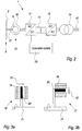
- Fig. 2 illustrates schematically the components of one embodiment of the present invention a direct driven pitch controlled variable speed synchronous generator wind turbine 7 comprising a wind turbine rotor 8 comprising wind turbine blades 5 substantially directly connected without a gear via a rotor shaft 21 to the rotating rotor 9 of a large multi pole generator 10 comprising permanent magnets, the stator 16 connected to a generator side AC/DC converter 11 for converting generated AC to a DC-link 12, a grid side DC/AC converter 13 and a transformer 14 for transformation to required grid voltage of the utility grid 15.
- a converter control system 23 is connected to said converters 11, 13 in order to control their performance.
- the invention relates to gear-less wind turbines operating synchronous with generator speed in the range of e.g. 5 to 25 rpm.
- the invention relates to large scale wind turbines with one or more gear stages operating synchronous with generator speed in the range of e.g. 15 to 3000 rpm.
- said large multi pole generator 10 can be of at least 3 different principal generator types i.e. an axial-flux generator 18, radial-flux generator 17 and transverse-flux generator.
- the basic difference between said generator types is the way the generated magnetic flux in the stator coils 19 are oriented relative to the rotor axis or rotor shaft 21 of the wind turbine.
- Fig. 3a and fig. 3b illustrates schematically the principle construction of an axial-flux 18 and a radial-flux 17 generator respectively. Both types of generators comprise stator coils 19 and permanent magnets 20 connected to a rotating rotor shaft 21. Arrows 22 indicates the direction of the magnet flux.
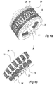
- FIG. 4a One embodiment of a large multipole generator is illustrated in fig. 4a comprising permanent magnets 20 connected to a rotor shaft 21 rotating between two rows of stator coils 19 with iron yokes 24.
- Fig. 4b illustrates in an explored view, a momentary flow of magnetic flux in this embodiment. Arrows 22 indicates the directions.
- a generator can comprise more than one generator sections, each section principle constructed e.g. as fig. 3a and/or fig. 3b i.e. with a rotor comprising PM material and a number of stator sections.
- the present invention comprises installation of said permanent magnets 20, or PM material, in the rotor 9 of a large scale wind turbine in a substantially non-magnetized condition. Magnetization of the permanent magnets 20 is done when they are installed in the rotor 9. The installation may be done by use of special designed tools.
- the design of the large generator 10 comprises design of special holding means for mounting said PM material 20 on the rotor 9.
- the holding means must be designed as to give an optimal and easy access for mounting the PM material 20 and furthermore ensure that the magnets 20 are retained in a desired and correct position during magnetization and during operation.
- the design can comprise special shaped PM materials 20 as well as special shaped retainers 26 and/or holding means.
- Fig. 5a illustrates parts of a side cross-view of a large generator 10 according to one embodiment of the invention, comprising stator coils 19 with iron yoke material 24, stator isolators 25 between stator coils 19, rotor permanent magnets 20 and magnet retainers 26 for fastening said magnets to the rotor base 27.
- the shapes of permanent magnets 20 and the retainers 26 are adapted as to fit each other, in order to ensure an optimal fastening to the rotor base 27.
- the retainers 26 can be fixed parts of the rotor base 27, separate parts but fixed mounted on the rotor base 27 or separate parts detachable from the rotor base 27 and can be made of magnetic or non-magnetic material depending on the specific embodiment. Furthermore for embodiments of the present invention, said rotor permanent magnets 20 are held in position by holding means such as adhesive, screws, bolts, clamps, clips or the like.
- said magnets are covered by a holding layer for fastening said magnets to the rotor base 27.
- Said holding layer can be of magnetic or non-magnetic material.
- the substantially non-magnetized rotor permanent magnets 20 can be mounted in said holding means before or after the rotor 9 is mounted in the generator.
- Magnetizing the PM materials 20 comprises placing the material in an external magnetic field e.g. produced by a solenoid with a direct current passing through it. When the field is removed, the PM material 20 retains some of the magnetism with a magnetic pole orientation defined by the applied magnetic field.
- said solenoid can be one or more magnetization coils designed for magnetization operation.
- stator coils 19 and/or the magnetizing coils 31 can be super conducting coils.
- magnetization of the magnets 20 can be done by stator coils 19.
- Fig. 5b illustrates for various embodiments of the invention a substantially non magnetic solid retaining material 34 is established in the air gap between the rotor permanent magnet 20 and the magnetization coil 31 in order to support the permanent magnet for retaining in position during the magnetization procedure, as extensive forces act on the magnets.
- the magnetization coils 31 are pressed against the permanent magnets 20 during said magnetization procedure.
- Fig. 6 illustrates schematically the functional concept of magnetizing a rotor for one embodiment of the invention, comprising magnetizing coils 31, rotor permanent magnets 20 and magnet retainers 26 for fastening said magnets to the rotor base 27.
- the shape of permanent magnets 20 and their retainers 26 are adapted as to fit each other, in order to ensure an optimal fastening to the rotor base 27.
- a magnetization controller 28 is used during the magnetization process in order to control one or more parameters vital for the process such as voltage (V), current (A), time, temperature, position of rotor 9, level of magnetization, magnetic field etc.
- the magnetization controller 28 is electrically connected to terminals 29 of one or more magnetizing coils 31.
- terminals 29 of coils not connected to said magnetization controller 28 can be connected to a proper termination 30 or can be left non-terminated.
- the one or more magnetization coils 31 used for magnetization are the stator coils 19 also used during normal operation or special purpose magnetization coils 31 used only during magnetization.
- special purpose magnetization coils 31 can be part of the stator construction during normal operation or can be temporary mounted in close proximity to the PM material 20 during the magnetization procedure only e.g. by replacing one or more sections of normal operation stator coils 19 by one or more sections of special purpose magnetization coils 31.
- the position of the rotor 9 is controlled in such a way that it is rotated in order to place the rotor permanent magnets 20 intended to be magnetized on a desired position relative to the said magnetization coils 31.
- the rotor 9 is kept at a fixed position and the positioning of said magnetization coils 31 are altered as to be positioned on a desired position relative to the rotor permanent magnets 20 intended to be magnetized.
- both the rotor 9 and the magnetization coils 31 are altered during a magnetization procedure.
- the generator comprising rotor- and stator construction and supporting structures is designed as to handle the excessive mechanical forces produced during magnetization and during operation.
- the level to which the permanent magnets 20 are magnetized during the magnetization procedure is controlled by said magnetization controller 28 and can be chosen dependent on parameters such as stability, degeneration of magnetic field over time, magnetization current, magnetization voltage etc.
- the magnetization current needed by magnetization coils 31 for the magnetization is supplied by at least one power converter 11,13 or section or combined sections of said power converter.
- the magnetization current needed by magnetization coils 31 for the magnetization is supplied by one or more power converters dedicated to said magnetization.
- said power converters supplying current to the magnetization coils 31 can be either power converters 11, 13 of the wind turbine or converters common to more than one wind turbine such as transportable power converters dedicated magnetization purposes.
Landscapes
- Engineering & Computer Science (AREA)
- Power Engineering (AREA)
- General Engineering & Computer Science (AREA)
- Physics & Mathematics (AREA)
- Sustainable Energy (AREA)
- Chemical & Material Sciences (AREA)
- Combustion & Propulsion (AREA)
- Mechanical Engineering (AREA)
- Life Sciences & Earth Sciences (AREA)
- Sustainable Development (AREA)
- Manufacturing & Machinery (AREA)
- Condensed Matter Physics & Semiconductors (AREA)
- General Physics & Mathematics (AREA)
- Wind Motors (AREA)
- Connection Of Motors, Electrical Generators, Mechanical Devices, And The Like (AREA)
- Permanent Magnet Type Synchronous Machine (AREA)
- Manufacture Of Motors, Generators (AREA)
- Control Of Eletrric Generators (AREA)
Abstract
manufacturing a generator prepared for taking one or more PM rotors,
manufacturing one or more rotors comprising a plurality of holding means prepared for retaining PM material,
mounting substantially non-magnetized PM material prepared for magnetization in said holding means before or after said one or more rotors are mounted in said generator,
connecting a magnetization system for magnetizing said PM material in the generator, and
magnetizing said PM material with said magnetization system.
Description
- The invention relates to a method for establishing a wind turbine generator with one or more Permanent Magnet (PM) rotors, a wind turbine nacelle and wind turbine.
- Assembling a large scale wind turbine generator comprises the installation of a rotor in stator.
- For a PM wind turbine generator of large scale, excessive magnetic forces will interact between magnets of the rotor and iron of the stator resulting in a complicated installation setup.
- Disclosed in Danish patent
DK 172430 -
US 2003/0071467 A1 , which is considered as the closest prior art to the subject-matter ofclaim 1, discloses a wind turbine with a PM alternator that uses a controller which is able to adjust the magnetization of the alternator in order to optimise the turbine performance. - A disadvantage by the described method is that at the installation extensive magnetic forces act between the magnets and other magnetic components of the electrical machine. This requires special precautions to be taken during installation comprising special tools for holding, lifting and handling the magnets, magnetic components and the forces that interact between them. Furthermore in the case of large scale machines, personel safety has to taken into account.
- It is an object of the invention to provide technique without the above mentioned disadvantages and especially it is an object to provide technique that excludes the requirement of specialized tools specific for the transportation and installation of large magnetized magnets in a rotor.
- The invention relates to a method for establishing a wind turbine generator with one or more Permanent Magnet (PM) rotors comprising the steps of:
- mounting substantially non-magnetized PM material in one or more rotors,
- establishing a magnetization field for magnetizing said PM material in the generator, and
- magnetizing said PM material with said magnetization field.
- By magnetizing the PM material after it is mounted on the rotor of e.g. a large scale wind turbine generator it is ensured that problematic issues regarding transporting, handling and assembling magnetized magnets are minimized e.g. the requirement of special non-magnetic lifting, installation and positioning tools and equipment to withstand the large magnetic field from said magnets are reduced substantially to a need for equipment capable of lifting the substantially non-magnetized magnets.
- Furthermore it is ensured that special precautions regarding personel safety and transport of magnetic material and special precautions for the existence of e.g. magnetic field sensitive components near said magnet and/or loose magnetic materials such as magnetic dust and small iron particles, is minimized.
- It is furthermore ensured that mounting said non-magnetized PM material can be established with equipment that can be made of magnetic material.
- Even further it is ensured that the PM material mounted in said holding means can be magnetized to a level at least equal to similar PM material that is magnetized in another location than when mounted in the holding means.
- Further it is ensured that i.e. a correct positioning of the PM material on the rotor can be obtained resulting in e.g. a uniform air gap between the rotor and the stator of the generator. This in turn results in an improved performance such as a better balance of the rotor, a more uniform induction of the stator coils during operation etc.
- In another aspect of the invention said mounting of substantially non-magnetized PM material and subsequent magnetization of PM material are performed when the wind turbine generator is installed in a wind turbine nacelle. Hereby it is ensured that said wind turbine generator can be installed in a non-magnetized condition and that no extra special designed tools are required as to withstand the excessive magnetic forces of magnetized PM material during installation. Furthermore it is ensured that the magnetization can be performed after the nacelle is assembled e.g. in a factory.
- In another aspect of the invention said mounting of substantially non-magnetized PM material and subsequent magnetization of PM material are performed on the wind turbine generator before or after mounting the nacelle on a wind turbine tower. Hereby it is ensured that the magnetization can be performed on a suitable location and/or at a suitable time in the installation process of a wind turbine. Furthermore special precautions regarding transportation can be minimized. Even further it is ensured that the magnetization can be performed when magnetization means is available and operating.
- In another aspect of the invention the magnetization of PM material is supplied by a magnetization system comprising magnetization coil means and at least one power supply. Hereby it is ensured that tools for magnetization are available. Furthermore it is ensured that it is possible to establish a magnetization system that is adapted as to supply correct and sufficient parameters of the magnetization process such as current, voltage, magnetic field, time control etc.
- In another aspect of the invention the magnetization current to said magnetization coil means is supplied by at least one power converter or section of said power converter as power supply. By a power converter is here meant an existing power converter of the wind turbine used to supply the utility grid during normal operation. Hereby it is ensured that existing power converters of the wind turbine can be used as power supply in said magnetization system which in turn reduces the requirements and costs to special dedicated magnetization tools. For different embodiments said supply of magnetization current to said magnetization coil can be supplied before or after the wind turbine nacelle is installed on a wind turbine tower.
- In another aspect of the invention said magnetization current to said magnetization coil means is supplied by one or more power converters dedicated to said magnetization of PM material. Hereby it is ensured that said dedicated power converters can supply correct and sufficient parameters of the magnetization process such as current, voltage, magnetic field, time control etc. Furthermore it is ensured for different embodiments that said dedicated power converter can be made mobile and can be used to magnetization on different wind turbines. Hereby a reduction of investment in specialized magnetization equipment can be reduced,
- In another aspect of the invention said magnetization current to said magnetization coil means is supplied by at least one power converter of the wind turbine or section of said power converter of the wind turbine. By using the wind turbine power converter it is ensured that the converter is available when needed for magnetization purposes. Furthermore it is ensured that electrical connection between converter and magnetization coil may be established. Even further it is ensured that sections of the power converter can be combined as to establish an optimal and sufficient magnetization current.
- In another aspect of the invention said connecting a magnetization system comprises connecting one or more magnetization coils that are designed for magnetization of PM material. Hereby it is ensured that an optimal level of magnetization can be obtained. Furthermore it is ensured that said coils can be special designed as to manage excessive parameters of the magnetization process such as current, voltage etc.
- In another aspect of the invention said magnetization coils are integrated in the stator or are replacing one or more stator parts of the wind turbine generator during magnetization of PM material. Hereby it is ensured that the PM material can be magnetized when the one or more rotors are installed in the generator. Furthermore it is ensured that stator coils also used for normal operation can be used as magnetization coils during the magnetization process. Even further it is ensured that stator parts can be replaced by stator coils used for the magnetization only.
- In another aspect of the invention said magnetization coils are dedicated for magnetization of PM material. Hereby it is ensured that the said magnetization stator coils can be designed as to sufficiently handle parameters of the magnetization such as current, voltage, magnetic field, magnetic forces. Furthermore it is ensured that magnetization can be managed substantially simultaneous to normal operation.
- In a further aspect of the invention said connecting a magnetization system comprises establishing a solid retaining material in the air gap between the rotor permanent magnet and the magnetization coil during the magnetization of PM material. Hereby it is ensured that the PM material is retained in its position during magnetization even though extensive mechanical forces are acting on the material. It is furthermore ensured that also the magnetization coil is retained on position during said magnetization.
- In another aspect of the invention said magnetizing of PM material comprises a continuous or stepwise rotation of said one or more permanent magnet rotors. Hereby it is ensured that said magnetization coils can be installed in a fixed position during the magnetization procedure whereby it in turn further can be ensured for different embodiments that only a minimum of time is needed for installing magnetizing equipment.
- In another aspect of the invention said magnetizing said PM material with said magnetization system comprises measuring and controlling one or more parameters vital for the process such as voltage (V), current (A), time, temperature, position of rotor, level of magnetization etc. Hereby it is ensured that an optimal and desired level of magnetization can be obtained and further that said level can be monitored.
- The invention also relates to a wind turbine nacelle and a wind turbine comprising said wind turbine nacelle.
- The invention will be described in the following with reference to the figures in which
- fig. 1
- illustrates a large modern wind turbine including three wind turbine blades in the wind turbine rotor,
- fig. 2
- illustrates schematically the components of one embodiment of a direct driven synchronous wind turbine,
- fig. 3a
- illustrates schematically the principle construction of an axial-flux generator,
- fig. 3b
- illustrates schematically the principle construction of an radial-flux generator,
- fig. 4a
- illustrates an axial-flux generator,
- fig.4b
- illustrates a momentary flow of magnetic flux in an axial-flux generator,
- fig. 5a
- illustrates schematically parts of a side cross-view of a large generator according to one embodiment of the invention,
- fig. 5b
- illustrates retaining material established in the air gap according to various embodiments of the invention, and
- fig. 6
- illustrates schematically stator coils of a cross-section of the invention.
-
Fig. 1 illustrates amodern wind turbine 1 with atower 2 and awind turbine nacelle 3 positioned on top of the tower. - The wind turbine rotor, comprising at least one blade such as three
wind turbine blades 5 as illustrated, is connected to thehub 4 throughpitch mechanisms 6. Each pitch mechanism includes a blade bearing and individual pitch actuating means which allows the blade to pitch. The pitch process is controlled by a pitch controller. - As indicated on the figure, wind over a certain level will activate the rotor and allow it to rotate in a substantially perpendicular direction to the wind. The rotation movement is converted to electric power by means comprising a generator and is usually supplied to the utility grid as will be known by skilled persons within the area.
- In general the use of electrical generators in large wind turbines comprises use of one of at least two basic types of generators i.e. generators based on electromagnetic or permanent magnets respectively. The present invention relates to a generator comprising permanent magnets (PM).
- PM generators comprises two components i.e. a rotating magnetic field constructed using permanent magnets and a stationary armature constructed using electrical windings located in a slotted iron core.
- In magnetized condition said permanent magnets have a North-seeking pole and a South-seeking pole respectively. Opposite pole types attract, while poles of the same type repel each other. Furthermore poles of either type attract iron, steel and a few other metals such as nickel and cobalt.
- Permanent magnets are made out of ferro- (or ferri-) magnetic material such as NdFeB, SiFe SrFeO or the like. During the formation of the magnetic material, very small atomic groups called magnetic domains act as one magnetic unit and produces a magnetic moment. The same domains align themselves in the same direction over a small volume. In non-magnetized condition the plurality domains of said permanent magnet are organized in a non-aligned way whereby the in a larger scale are substantially cancelling out each other resulting in no or a weak overall magnetic field.
- By magnetizing a ferromagnetic permanent magnet e.g. by placing it in an external magnetic field such as produced in a solenoid with a direct current passing through it, all domains tend to align with the external magnetic field. Some domains align more easily than others so the resulting magnetic moment depends how strong the applied magnetic fields is, increasing until all possible domains are aligned.
- If a ferromagnetic material is exposed for temperatures above its specific Curie temperature it loses its characteristic magnetic ability as thermal fluctuations destroy the alignment of said domains.
- Usually permanent magnets are substantially not magnetic when they are produced but must be magnetized later on, e,g, on the location of production, just before they are assembled or after they as components are built into e.g. generators.
-
Fig. 2 illustrates schematically the components of one embodiment of the present invention a direct driven pitch controlled variable speed synchronousgenerator wind turbine 7 comprising a wind turbine rotor 8 comprisingwind turbine blades 5 substantially directly connected without a gear via arotor shaft 21 to the rotating rotor 9 of a largemulti pole generator 10 comprising permanent magnets, thestator 16 connected to a generator side AC/DC converter 11 for converting generated AC to a DC-link 12, a grid side DC/AC converter 13 and atransformer 14 for transformation to required grid voltage of theutility grid 15. - A
converter control system 23 is connected to saidconverters - In various embodiments the invention relates to gear-less wind turbines operating synchronous with generator speed in the range of e.g. 5 to 25 rpm.
- In other embodiments the invention relates to large scale wind turbines with one or more gear stages operating synchronous with generator speed in the range of e.g. 15 to 3000 rpm.
- For different embodiments said large
multi pole generator 10 can be of at least 3 different principal generator types i.e. an axial-flux generator 18, radial-flux generator 17 and transverse-flux generator. The basic difference between said generator types is the way the generated magnetic flux in the stator coils 19 are oriented relative to the rotor axis orrotor shaft 21 of the wind turbine. -
Fig. 3a and fig. 3b illustrates schematically the principle construction of an axial-flux 18 and a radial-flux 17 generator respectively. Both types of generators comprise stator coils 19 andpermanent magnets 20 connected to arotating rotor shaft 21.Arrows 22 indicates the direction of the magnet flux. - One embodiment of a large multipole generator is illustrated in
fig. 4a comprisingpermanent magnets 20 connected to arotor shaft 21 rotating between two rows of stator coils 19 with iron yokes 24. -
Fig. 4b illustrates in an explored view, a momentary flow of magnetic flux in this embodiment.Arrows 22 indicates the directions. - For different embodiments of the invention, a generator can comprise more than one generator sections, each section principle constructed e.g. as
fig. 3a and/orfig. 3b i.e. with a rotor comprising PM material and a number of stator sections. - The assembly of a large generator with pre-magnetized magnets requires large mechanical forces as to withstand excessive magnetic forces produced between generator components.
- The present invention comprises installation of said
permanent magnets 20, or PM material, in the rotor 9 of a large scale wind turbine in a substantially non-magnetized condition. Magnetization of thepermanent magnets 20 is done when they are installed in the rotor 9. The installation may be done by use of special designed tools. - For different embodiments of the invention the design of the
large generator 10 comprises design of special holding means for mounting saidPM material 20 on the rotor 9. The holding means must be designed as to give an optimal and easy access for mounting thePM material 20 and furthermore ensure that themagnets 20 are retained in a desired and correct position during magnetization and during operation. For various embodiments of the invention the design can comprise special shapedPM materials 20 as well as special shapedretainers 26 and/or holding means. -
Fig. 5a illustrates parts of a side cross-view of alarge generator 10 according to one embodiment of the invention, comprising stator coils 19 withiron yoke material 24,stator isolators 25 between stator coils 19, rotorpermanent magnets 20 andmagnet retainers 26 for fastening said magnets to therotor base 27. For this embodiment the shapes ofpermanent magnets 20 and theretainers 26 are adapted as to fit each other, in order to ensure an optimal fastening to therotor base 27. - For various embodiments of the present invention, the
retainers 26 can be fixed parts of therotor base 27, separate parts but fixed mounted on therotor base 27 or separate parts detachable from therotor base 27 and can be made of magnetic or non-magnetic material depending on the specific embodiment. Furthermore for embodiments of the present invention, said rotorpermanent magnets 20 are held in position by holding means such as adhesive, screws, bolts, clamps, clips or the like. - For other embodiments of the invention said magnets are covered by a holding layer for fastening said magnets to the
rotor base 27. Said holding layer can be of magnetic or non-magnetic material. - According to different embodiments of the present invention, the substantially non-magnetized rotor
permanent magnets 20 can be mounted in said holding means before or after the rotor 9 is mounted in the generator. - Magnetizing the
PM materials 20 comprises placing the material in an external magnetic field e.g. produced by a solenoid with a direct current passing through it. When the field is removed, thePM material 20 retains some of the magnetism with a magnetic pole orientation defined by the applied magnetic field. - For embodiments of the invention said solenoid can be one or more magnetization coils designed for magnetization operation.
- For various embodiments of the invention the stator coils 19 and/or the magnetizing coils 31 can be super conducting coils.
- For one embodiment of the invention where the rotor 9 is mounted in the large generator and
permanent magnets 20 are installed in the holding means of the rotor 9, magnetization of themagnets 20 can be done by stator coils 19. -
Fig. 5b illustrates for various embodiments of the invention a substantially non magneticsolid retaining material 34 is established in the air gap between the rotorpermanent magnet 20 and themagnetization coil 31 in order to support the permanent magnet for retaining in position during the magnetization procedure, as extensive forces act on the magnets. - In one embodiment the magnetization coils 31 are pressed against the
permanent magnets 20 during said magnetization procedure. -
Fig. 6 illustrates schematically the functional concept of magnetizing a rotor for one embodiment of the invention, comprising magnetizing coils 31, rotorpermanent magnets 20 andmagnet retainers 26 for fastening said magnets to therotor base 27. For this embodiment of the invention, the shape ofpermanent magnets 20 and theirretainers 26 are adapted as to fit each other, in order to ensure an optimal fastening to therotor base 27. - A
magnetization controller 28 is used during the magnetization process in order to control one or more parameters vital for the process such as voltage (V), current (A), time, temperature, position of rotor 9, level of magnetization, magnetic field etc. - As illustrated in
fig. 6 themagnetization controller 28 is electrically connected toterminals 29 of one or more magnetizing coils 31. - During the
magnetization procedure terminals 29 of coils not connected to saidmagnetization controller 28 can be connected to aproper termination 30 or can be left non-terminated. - For different embodiments of the invention, the one or more magnetization coils 31 used for magnetization are the stator coils 19 also used during normal operation or special purpose magnetization coils 31 used only during magnetization.
- Furthermore said special purpose magnetization coils 31 can be part of the stator construction during normal operation or can be temporary mounted in close proximity to the
PM material 20 during the magnetization procedure only e.g. by replacing one or more sections of normal operation stator coils 19 by one or more sections of special purpose magnetization coils 31. - For one embodiment of the invention during a magnetization procedure, the position of the rotor 9 is controlled in such a way that it is rotated in order to place the rotor
permanent magnets 20 intended to be magnetized on a desired position relative to the said magnetization coils 31. - For another embodiment of the invention during a magnetization procedure, the rotor 9 is kept at a fixed position and the positioning of said magnetization coils 31 are altered as to be positioned on a desired position relative to the rotor
permanent magnets 20 intended to be magnetized. - For yet another embodiment both the rotor 9 and the magnetization coils 31 are altered during a magnetization procedure.
- For all embodiments the generator comprising rotor- and stator construction and supporting structures is designed as to handle the excessive mechanical forces produced during magnetization and during operation.
- The level to which the
permanent magnets 20 are magnetized during the magnetization procedure is controlled by saidmagnetization controller 28 and can be chosen dependent on parameters such as stability, degeneration of magnetic field over time, magnetization current, magnetization voltage etc. - For one embodiment of the invention the magnetization current needed by
magnetization coils 31 for the magnetization is supplied by at least onepower converter - For another embodiment of the invention the magnetization current needed by
magnetization coils 31 for the magnetization is supplied by one or more power converters dedicated to said magnetization. - For various embodiments of the invention said power converters supplying current to the magnetization coils 31 can be either
power converters -
- 1.
- Wind turbine
- 2.
- Tower
- 3.
- Nacelle
- 4.
- Hub
- 5.
- Rotor blade
- 6.
- Pitch mechanism
- 7.
- Direct driven synchronous wind turbine
- 8.
- Wind turbine rotor
- 9.
- Rotating rotor of generator
- 10.
- Large multipole generator
- 11.
- AC/DC converter
- 12.
- DC-link
- 13.
- DC/AC converter
- 14.
- Transformer
- 15.
- Utility grid
- 16.
- Stator
- 17.
- Radial-flux generator
- 18.
- Axial-flux generator
- 19.
- Stator coils
- 20.
- Rotor permanent magnets or PM material
- 21.
- Rotor shaft
- 22.
- Arrows indicating magnetic-flux
- 23.
- Converter control system
- 24.
- Stator coil iron yoke
- 25,
- Stator isolator
- 26.
- Magnet retainer
- 27.
- Rotor base
- 28,
- Magnetization controller
- 29.
- Coil terminals
- 30.
- Termination
- 31.
- Magnetization coil
- 32.
- Rotor pole
- 33.
- Stator yoke
- 34.
- Solid retaining material
Claims (28)
- Method for establishing a wind turbine generator with one or more Permanent Magnet (PM) rotors comprising the steps of:- mounting substantially non-magnetized PM material in one or more rotors,- establishing a magnetization field for magnetizing said PM material in the generator, and- magnetizing said PM material with said magnetization field.
- Method according to claim 1, wherein said substantially non-magnetized PM material prepared for magnetization before said one or more rotors are mounted in said generator.
- Method according to claims 1, wherein said substantially non-magnetized PM material prepared for magnetization after said one or more rotors are mounted in said generator.
- Method according to any of claims 1 to 3, wherein said substantially non-magnetized PM material prepared for magnetization are retained in a plurality of holding means.
- Method according to any of claims 1 to 4, wherein said magnetization field is established by a connected magnetization system.
- Method according to claim 1, wherein said mounting of substantially non-magnetized PM material and subsequent magnetization of PM material are performed when the wind turbine generator is installed in a wind turbine nacelle.
- Method according to claims 1, wherein said mounting of substantially non-magnetized PM material and subsequent magnetization of PM material are performed on the wind turbine generator before or after mounting the nacelle on a wind turbine tower.
- Method according to claim 1, wherein the magnetization of PM material is supplied by a magnetization system comprising magnetization coil means and at least one power supply.
- Method according to claim 8, wherein magnetization current to said magnetization coil means is supplied by at least one power converter or section of said power converter as power supply.
- Method according to claim 8 or 9, wherein said magnetization current to said magnetization coil means is supplied by one or more power converters dedicated to said magnetization of PM material.
- Method according to any of claims 8 to 10, wherein said magnetization current to said magnetization coil means is supplied by at least one power converter of the wind turbine or section of said power converter of the wind turbine.
- Method according to claim 1, wherein said connecting a magnetization system comprises connecting one or more magnetization coils that are designed for magnetization of PM material.
- Method according to claim 12, wherein said magnetization coils are integrated in the stator or are replacing one or more stator parts of the wind turbine generator during magnetization of PM material.
- Method according to claims 12 or 13, wherein said magnetization coils are dedicated for magnetization of PM material.
- Method according to claim 1, wherein said connecting a magnetization system comprises establishing a solid retaining material in the air gap between the rotor permanent magnet and the magnetization coil during the magnetization of PM material.
- Method according to claim 1, wherein said magnetizing of PM material comprises a continuous or stepwise rotation of said one or more permanent magnet rotors.
- Method according to claim 1, wherein said magnetizing said PM material with said magnetization system comprises measuring and controlling one or more parameters vital for the process such as voltage (V), current (A), time, temperature, position of rotor, level of magnetization etc.
- Wind turbine nacelle comprising:- a wind turbine generator with one or more rotors, and- PM material mounted and magnetized by a method according to any of claims 1 to 17.
- Wind turbine nacelle according to claim 18 wherein said PM material is mounted and magnetized in holding means.
- Wind turbine nacelle according to claim 18, wherein said wind turbine generator is an axial-flux generator, a radial-flux generator or a transversal-flux generator.
- Wind turbine nacelle according to claim 18, wherein said PM material magnetization is being performed with a magnetization system comprising magnetization coil means and at least one power supply.
- Wind turbine nacelle according to claim 21, wherein magnetization current to said magnetization coil means is supplied by at least one power converter or section of said converter as power supply.
- Wind turbine nacelle according to claims 21 or 22, wherein said magnetization current to said magnetization coil means is supplied by one or more power converters dedicated to said magnetization,
- Wind turbine nacelle according to any of claims 21 to 23, wherein said magnetization current to said magnetization coil means is supplied by at least one power converter of the wind turbine or section of said power converter of the wind turbine.
- Wind turbine nacelle according to claim 18, wherein said magnetization system comprises one or more stator coils that are designed for magnetization operation.
- Wind turbine comprising:- a wind turbine tower,- a wind turbine rotor, and- a wind turbine nacelle according to any of claims 18 to 25 positioned on said tower and connected to said wind turbine rotor.
- Wind turbine according to claim 26, further comprising one or more power converters for supplying current to said magnetizing system.
- Wind turbine according to claim 26, further comprising a gear with one or more stages.
Applications Claiming Priority (2)
| Application Number | Priority Date | Filing Date | Title |
|---|---|---|---|
| DKPA200700455 | 2007-03-23 | ||
| EP08715591.7A EP2126352B2 (en) | 2007-03-23 | 2008-03-19 | Method for establishing a wind turbine generator with one or more permanent magnet (pm) rotors, wind turbine nacelle and wind turbine |
Related Parent Applications (3)
| Application Number | Title | Priority Date | Filing Date |
|---|---|---|---|
| EP08715591.7A Division EP2126352B2 (en) | 2007-03-23 | 2008-03-19 | Method for establishing a wind turbine generator with one or more permanent magnet (pm) rotors, wind turbine nacelle and wind turbine |
| EP08715591.7A Division-Into EP2126352B2 (en) | 2007-03-23 | 2008-03-19 | Method for establishing a wind turbine generator with one or more permanent magnet (pm) rotors, wind turbine nacelle and wind turbine |
| EP08715591.7 Division | 2008-03-19 |
Publications (3)
| Publication Number | Publication Date |
|---|---|
| EP2299112A2 true EP2299112A2 (en) | 2011-03-23 |
| EP2299112A3 EP2299112A3 (en) | 2013-06-19 |
| EP2299112B1 EP2299112B1 (en) | 2015-05-13 |
Family
ID=39719036
Family Applications (2)
| Application Number | Title | Priority Date | Filing Date |
|---|---|---|---|
| EP08715591.7A Active EP2126352B2 (en) | 2007-03-23 | 2008-03-19 | Method for establishing a wind turbine generator with one or more permanent magnet (pm) rotors, wind turbine nacelle and wind turbine |
| EP20100013933 Active EP2299112B1 (en) | 2007-03-23 | 2008-03-19 | Method for establishing a wind turbine generator with one or more permanent magnet (pm) rotors, wind turbine nacelle and wind turbine |
Family Applications Before (1)
| Application Number | Title | Priority Date | Filing Date |
|---|---|---|---|
| EP08715591.7A Active EP2126352B2 (en) | 2007-03-23 | 2008-03-19 | Method for establishing a wind turbine generator with one or more permanent magnet (pm) rotors, wind turbine nacelle and wind turbine |
Country Status (7)
| Country | Link |
|---|---|
| US (1) | US8468681B2 (en) |
| EP (2) | EP2126352B2 (en) |
| CN (1) | CN101657635B (en) |
| AT (1) | ATE486216T1 (en) |
| DE (1) | DE602008003201D1 (en) |
| ES (2) | ES2544497T3 (en) |
| WO (1) | WO2008116464A2 (en) |
Cited By (1)
| Publication number | Priority date | Publication date | Assignee | Title |
|---|---|---|---|---|
| WO2021155872A1 (en) | 2020-02-05 | 2021-08-12 | Petr Orel | Magnetic turbine and magnetic turbine assembly |
Families Citing this family (19)
| Publication number | Priority date | Publication date | Assignee | Title |
|---|---|---|---|---|
| NL2001190C1 (en) * | 2008-01-16 | 2009-07-20 | Lagerwey Wind B V | Generator for a direct-driven wind turbine. |
| DE102009005956A1 (en) * | 2009-01-23 | 2010-07-29 | Avantis Ltd. | magnetic ring |
| DE102009006017A1 (en) * | 2009-01-23 | 2010-08-05 | Avantis Ltd. | magnetic wheel |
| US8766753B2 (en) * | 2009-07-09 | 2014-07-01 | General Electric Company | In-situ magnetizer |
| IT1395148B1 (en) * | 2009-08-07 | 2012-09-05 | Rolic Invest Sarl | METHOD AND APPARATUS FOR ACTIVATION OF AN ELECTRIC MACHINE AND ELECTRIC MACHINE |
| US8664819B2 (en) * | 2009-08-18 | 2014-03-04 | Northern Power Systems Utility Scale, Inc. | Method and apparatus for permanent magnet attachment in an electromechanical machine |
| US9515529B2 (en) | 2009-08-18 | 2016-12-06 | Northern Power Systems, Inc. | Method and apparatus for permanent magnet attachment in an electromechanical machine |
| US8373319B1 (en) | 2009-09-25 | 2013-02-12 | Jerry Barnes | Method and apparatus for a pancake-type motor/generator |
| WO2011100987A1 (en) * | 2010-02-16 | 2011-08-25 | Siemens Aktiengesellschaft | Method for assembling part of a generator, generator and wind turbine |
| WO2012000503A2 (en) * | 2010-06-30 | 2012-01-05 | Vestas Wind Systems A/S | Apparatus and methods for magnetizing and demagnetizing magnetic poles in an electrical machine |
| ES2428017T3 (en) * | 2011-04-04 | 2013-11-05 | Siemens Aktiengesellschaft | Procedure to mount an electric machine |
| EP2528184B1 (en) * | 2011-05-25 | 2014-09-10 | Siemens Aktiengesellschaft | Method and apparatus for controlling a DC-transmission link |
| EP2605371B1 (en) * | 2011-12-13 | 2014-08-13 | Siemens Aktiengesellschaft | Magnetic component part comprising different magnetic materials |
| FR2989541B1 (en) * | 2012-04-16 | 2015-05-08 | Converteam Technology Ltd | METHOD FOR MAGNETIZING A PERMANENT MAGNET POLE OF AN ELECTRIC MACHINE WITH DISASSEMBLY STATORIC PLATES AND ELECTRIC MACHINE |
| NO337934B1 (en) * | 2014-10-23 | 2016-07-11 | Rolls Royce Marine As | Method of assembling rotors comprising permanent magnets |
| EP3038239B1 (en) * | 2014-12-24 | 2020-03-11 | GE Renewable Technologies Wind B.V. | Methods of assembling an electrical machine |
| US10261107B2 (en) * | 2015-03-31 | 2019-04-16 | University Of Kansas | Scanning resonator microscopy |
| US10454323B2 (en) | 2016-08-01 | 2019-10-22 | Ge Oil & Gas Esp, Inc. | Permanent magnet based electric machine and method of manufacturing the same |
| EP4089893A1 (en) * | 2021-05-10 | 2022-11-16 | General Electric Renovables España S.L. | Armature assemblies for generators and assembly methods |
Citations (2)
| Publication number | Priority date | Publication date | Assignee | Title |
|---|---|---|---|---|
| DK172430B1 (en) | 1994-12-19 | 1998-06-08 | Belt Electric V Peter Rasmusse | Method for installing or disinstalling a permanently magnetised electrical machine with many poles |
| US20030071467A1 (en) | 2001-10-12 | 2003-04-17 | Calley David Gregory | Wind turbine controller |
Family Cites Families (22)
| Publication number | Priority date | Publication date | Assignee | Title |
|---|---|---|---|---|
| US2212192A (en) * | 1938-12-08 | 1940-08-20 | Frank Raffles | Electromagnetic apparatus |
| DE3138052C2 (en) † | 1981-09-24 | 1983-07-28 | Siemens AG, 1000 Berlin und 8000 München | Magnetizing device for magnetizing the permanent magnet arrangement of a dynamo-electric machine and method for magnetizing |
| DE3510985A1 (en) † | 1985-03-22 | 1986-09-25 | Siemens AG, 1000 Berlin und 8000 München | ELECTRIC MACHINE SYNCHRONOUS TYPE WITH PERMANENT MAGNET |
| JPS6323541A (en) † | 1986-03-05 | 1988-01-30 | Hitachi Ltd | Magnetization of motor |
| JPH0697825B2 (en) † | 1989-02-20 | 1994-11-30 | 株式会社三ツ葉電機製作所 | External magnetizing method and external magnetizing device in permanent magnet rotating electric machine |
| JP2943657B2 (en) * | 1994-08-02 | 1999-08-30 | トヨタ自動車株式会社 | Control device for salient pole type permanent magnet motor |
| BR9706334B1 (en) | 1997-12-29 | 2009-08-11 | magnetization process of the permanent magnets of an electric motor rotor and hermetic compressor motor assembly process. | |
| JP3749389B2 (en) † | 1999-02-02 | 2006-02-22 | 東芝キヤリア株式会社 | Magnetizing method of motor for compressor |
| DE19914021C2 (en) † | 1999-03-19 | 2002-01-31 | Siemens Ag | Multi-pole, permanently excited rotor for a rotating electrical machine and method for producing such a rotor |
| US6720792B2 (en) * | 2001-09-17 | 2004-04-13 | Ford Global Technologies, Llc | Detection of demagnetization in a motor in an electric or partially electric motor vehicle |
| JP4311643B2 (en) * | 2001-12-20 | 2009-08-12 | 三菱電機株式会社 | Method for manufacturing permanent magnet type rotating electric machine and method for manufacturing permanent magnet type synchronous generator for wind power generation |
| US6674205B2 (en) † | 2002-05-07 | 2004-01-06 | General Motors Corporation | Auxiliary magnetizing winding for interior permanent magnet rotor magnetization |
| US7042109B2 (en) | 2002-08-30 | 2006-05-09 | Gabrys Christopher W | Wind turbine |
| US6903640B2 (en) † | 2002-10-11 | 2005-06-07 | Emerson Electric Co. | Apparatus and method of using the stator coils of an electric motor to magnetize permanent magnets of the motor rotor when the span of each stator coil is smaller than the width of each permanent magnet pole |
| JP2004173415A (en) * | 2002-11-20 | 2004-06-17 | Mitsubishi Electric Corp | Permanent magnet rotating electric machine and permanent magnet generator for wind turbine power generation |
| US6794777B1 (en) * | 2003-12-19 | 2004-09-21 | Richard Benito Fradella | Robust minimal-loss flywheel systems |
| US7228616B2 (en) * | 2005-03-31 | 2007-06-12 | General Electric Company | System and method for magnetization of permanent magnet rotors in electrical machines |
| CA2614929A1 (en) * | 2005-07-28 | 2007-02-01 | Cleanfield Energy Corp. | Power generating system including modular wind turbine-generator assembly |
| US20070159281A1 (en) † | 2006-01-10 | 2007-07-12 | Liang Li | System and method for assembly of an electromagnetic machine |
| JP5157138B2 (en) † | 2006-11-24 | 2013-03-06 | 株式会社日立製作所 | Permanent magnet rotating electrical machine and wind power generation system |
| ES2387221T3 (en) * | 2007-03-23 | 2012-09-18 | Vestas Wind Systems A/S | Procedure for estimating the level of magnetization of one or more permanent magnets located in one or more permanent magnet rotors of a wind turbine generator and a wind turbine |
| US7646178B1 (en) * | 2009-05-08 | 2010-01-12 | Fradella Richard B | Broad-speed-range generator |
-
2008
- 2008-03-19 EP EP08715591.7A patent/EP2126352B2/en active Active
- 2008-03-19 ES ES10013933.6T patent/ES2544497T3/en active Active
- 2008-03-19 AT AT08715591T patent/ATE486216T1/en not_active IP Right Cessation
- 2008-03-19 EP EP20100013933 patent/EP2299112B1/en active Active
- 2008-03-19 CN CN2008800095339A patent/CN101657635B/en active Active
- 2008-03-19 DE DE602008003201T patent/DE602008003201D1/en active Active
- 2008-03-19 WO PCT/DK2008/000114 patent/WO2008116464A2/en active Application Filing
- 2008-03-19 ES ES08715591.7T patent/ES2354340T5/en active Active
-
2009
- 2009-09-23 US US12/565,577 patent/US8468681B2/en active Active
Patent Citations (2)
| Publication number | Priority date | Publication date | Assignee | Title |
|---|---|---|---|---|
| DK172430B1 (en) | 1994-12-19 | 1998-06-08 | Belt Electric V Peter Rasmusse | Method for installing or disinstalling a permanently magnetised electrical machine with many poles |
| US20030071467A1 (en) | 2001-10-12 | 2003-04-17 | Calley David Gregory | Wind turbine controller |
Cited By (1)
| Publication number | Priority date | Publication date | Assignee | Title |
|---|---|---|---|---|
| WO2021155872A1 (en) | 2020-02-05 | 2021-08-12 | Petr Orel | Magnetic turbine and magnetic turbine assembly |
Also Published As
| Publication number | Publication date |
|---|---|
| CN101657635B (en) | 2012-11-21 |
| EP2299112B1 (en) | 2015-05-13 |
| EP2299112A3 (en) | 2013-06-19 |
| ES2354340T5 (en) | 2017-10-20 |
| EP2126352B2 (en) | 2017-08-02 |
| DE602008003201D1 (en) | 2010-12-09 |
| US20100011567A1 (en) | 2010-01-21 |
| US8468681B2 (en) | 2013-06-25 |
| EP2126352B1 (en) | 2010-10-27 |
| CN101657635A (en) | 2010-02-24 |
| ES2544497T3 (en) | 2015-09-01 |
| ES2354340T3 (en) | 2011-03-14 |
| EP2126352A2 (en) | 2009-12-02 |
| ATE486216T1 (en) | 2010-11-15 |
| WO2008116464A2 (en) | 2008-10-02 |
| WO2008116464A3 (en) | 2009-04-23 |
Similar Documents
| Publication | Publication Date | Title |
|---|---|---|
| EP2126352B1 (en) | Method for establishing a wind turbine generator with one or more permanent magnet (pm) rotors, wind turbine nacelle and wind turbine | |
| EP2132862B1 (en) | Method for estimating the magnetization level of one or more permanent magnets established in one or more permanent magnet rotors of a wind turbine generator and wind turbine | |
| CN1866688B (en) | System and method for magnetization of permanent magnet rotors in electrical machines | |
| US9548153B2 (en) | Methods for magnetizing and demagnetizing magnetic poles in an electrical machine | |
| US20120169063A1 (en) | Permanent magnet generator | |
| KR20120127603A (en) | Magnet assembly | |
| US11837918B2 (en) | Magnets in electrical machines | |
| EP2548292A1 (en) | Components for generators, their use and stator mounting | |
| CN109256879A (en) | A kind of Double-stator motor of ectonexine permanent magnet dislocation | |
| CN209375272U (en) | A kind of Double-stator motor of ectonexine permanent magnet dislocation | |
| US11923117B2 (en) | Magnetizing permanent magnets | |
| US11909280B1 (en) | Modular electrical generator/electric motor assembly, and method of using same | |
| US11936246B2 (en) | Axial flux motor | |
| CN201113573Y (en) | Iron core stamping for large power permanent magnetism wind power generator |
Legal Events
| Date | Code | Title | Description |
|---|---|---|---|
| PUAI | Public reference made under article 153(3) epc to a published international application that has entered the european phase |
Free format text: ORIGINAL CODE: 0009012 |
|
| AC | Divisional application: reference to earlier application |
Ref document number: 2126352 Country of ref document: EP Kind code of ref document: P |
|
| AK | Designated contracting states |
Kind code of ref document: A2 Designated state(s): AT BE BG CH CY CZ DE DK EE ES FI FR GB GR HR HU IE IS IT LI LT LU LV MC MT NL NO PL PT RO SE SI SK TR |
|
| RIN1 | Information on inventor provided before grant (corrected) |
Inventor name: BENDIXEN, FLEMMING BUUS Inventor name: KJAER, PHILIP RICHARD JACOBSEN Inventor name: LINDHOLM, MORTEN Inventor name: BOLDEA, ION Inventor name: HELLE, LARS |
|
| RAP1 | Party data changed (applicant data changed or rights of an application transferred) |
Owner name: VESTAS WIND SYSTEMS A/S |
|
| PUAL | Search report despatched |
Free format text: ORIGINAL CODE: 0009013 |
|
| AK | Designated contracting states |
Kind code of ref document: A3 Designated state(s): AT BE BG CH CY CZ DE DK EE ES FI FR GB GR HR HU IE IS IT LI LT LU LV MC MT NL NO PL PT RO SE SI SK TR |
|
| RIC1 | Information provided on ipc code assigned before grant |
Ipc: F03D 1/00 20060101ALI20130514BHEP Ipc: H02K 15/03 20060101ALI20130514BHEP Ipc: H01F 13/00 20060101ALI20130514BHEP Ipc: H02K 7/18 20060101ALI20130514BHEP Ipc: F03D 9/00 20060101AFI20130514BHEP |
|
| 17P | Request for examination filed |
Effective date: 20131219 |
|
| RBV | Designated contracting states (corrected) |
Designated state(s): AT BE BG CH CY CZ DE DK EE ES FI FR GB GR HR HU IE IS IT LI LT LU LV MC MT NL NO PL PT RO SE SI SK TR |
|
| 17Q | First examination report despatched |
Effective date: 20140210 |
|
| RIC1 | Information provided on ipc code assigned before grant |
Ipc: H02K 7/18 20060101ALI20141203BHEP Ipc: F03D 1/00 20060101ALI20141203BHEP Ipc: G01R 33/12 20060101ALI20141203BHEP Ipc: F03D 9/00 20060101AFI20141203BHEP Ipc: H02K 15/03 20060101ALI20141203BHEP Ipc: H01F 13/00 20060101ALI20141203BHEP |
|
| GRAP | Despatch of communication of intention to grant a patent |
Free format text: ORIGINAL CODE: EPIDOSNIGR1 |
|
| INTG | Intention to grant announced |
Effective date: 20150108 |
|
| GRAS | Grant fee paid |
Free format text: ORIGINAL CODE: EPIDOSNIGR3 |
|
| GRAA | (expected) grant |
Free format text: ORIGINAL CODE: 0009210 |
|
| AC | Divisional application: reference to earlier application |
Ref document number: 2126352 Country of ref document: EP Kind code of ref document: P |
|
| AK | Designated contracting states |
Kind code of ref document: B1 Designated state(s): AT BE BG CH CY CZ DE DK EE ES FI FR GB GR HR HU IE IS IT LI LT LU LV MC MT NL NO PL PT RO SE SI SK TR |
|
| REG | Reference to a national code |
Ref country code: GB Ref legal event code: FG4D |
|
| REG | Reference to a national code |
Ref country code: CH Ref legal event code: EP |
|
| RAP2 | Party data changed (patent owner data changed or rights of a patent transferred) |
Owner name: VESTAS WIND SYSTEMS A/S |
|
| REG | Reference to a national code |
Ref country code: IE Ref legal event code: FG4D |
|
| REG | Reference to a national code |
Ref country code: AT Ref legal event code: REF Ref document number: 726962 Country of ref document: AT Kind code of ref document: T Effective date: 20150615 |
|
| REG | Reference to a national code |
Ref country code: DE Ref legal event code: R096 Ref document number: 602008038176 Country of ref document: DE Effective date: 20150625 |
|
| REG | Reference to a national code |
Ref country code: ES Ref legal event code: FG2A Ref document number: 2544497 Country of ref document: ES Kind code of ref document: T3 Effective date: 20150901 |
|
| REG | Reference to a national code |
Ref country code: AT Ref legal event code: MK05 Ref document number: 726962 Country of ref document: AT Kind code of ref document: T Effective date: 20150513 |
|
| REG | Reference to a national code |
Ref country code: NL Ref legal event code: MP Effective date: 20150513 |
|
| REG | Reference to a national code |
Ref country code: LT Ref legal event code: MG4D |
|
| PG25 | Lapsed in a contracting state [announced via postgrant information from national office to epo] |
Ref country code: FI Free format text: LAPSE BECAUSE OF FAILURE TO SUBMIT A TRANSLATION OF THE DESCRIPTION OR TO PAY THE FEE WITHIN THE PRESCRIBED TIME-LIMIT Effective date: 20150513 Ref country code: PT Free format text: LAPSE BECAUSE OF FAILURE TO SUBMIT A TRANSLATION OF THE DESCRIPTION OR TO PAY THE FEE WITHIN THE PRESCRIBED TIME-LIMIT Effective date: 20150914 Ref country code: HR Free format text: LAPSE BECAUSE OF FAILURE TO SUBMIT A TRANSLATION OF THE DESCRIPTION OR TO PAY THE FEE WITHIN THE PRESCRIBED TIME-LIMIT Effective date: 20150513 Ref country code: NO Free format text: LAPSE BECAUSE OF FAILURE TO SUBMIT A TRANSLATION OF THE DESCRIPTION OR TO PAY THE FEE WITHIN THE PRESCRIBED TIME-LIMIT Effective date: 20150813 Ref country code: LT Free format text: LAPSE BECAUSE OF FAILURE TO SUBMIT A TRANSLATION OF THE DESCRIPTION OR TO PAY THE FEE WITHIN THE PRESCRIBED TIME-LIMIT Effective date: 20150513 |
|
| PG25 | Lapsed in a contracting state [announced via postgrant information from national office to epo] |
Ref country code: GR Free format text: LAPSE BECAUSE OF FAILURE TO SUBMIT A TRANSLATION OF THE DESCRIPTION OR TO PAY THE FEE WITHIN THE PRESCRIBED TIME-LIMIT Effective date: 20150814 Ref country code: AT Free format text: LAPSE BECAUSE OF FAILURE TO SUBMIT A TRANSLATION OF THE DESCRIPTION OR TO PAY THE FEE WITHIN THE PRESCRIBED TIME-LIMIT Effective date: 20150513 Ref country code: LV Free format text: LAPSE BECAUSE OF FAILURE TO SUBMIT A TRANSLATION OF THE DESCRIPTION OR TO PAY THE FEE WITHIN THE PRESCRIBED TIME-LIMIT Effective date: 20150513 Ref country code: BG Free format text: LAPSE BECAUSE OF FAILURE TO SUBMIT A TRANSLATION OF THE DESCRIPTION OR TO PAY THE FEE WITHIN THE PRESCRIBED TIME-LIMIT Effective date: 20150813 Ref country code: IS Free format text: LAPSE BECAUSE OF FAILURE TO SUBMIT A TRANSLATION OF THE DESCRIPTION OR TO PAY THE FEE WITHIN THE PRESCRIBED TIME-LIMIT Effective date: 20150913 |
|
| PG25 | Lapsed in a contracting state [announced via postgrant information from national office to epo] |
Ref country code: DK Free format text: LAPSE BECAUSE OF FAILURE TO SUBMIT A TRANSLATION OF THE DESCRIPTION OR TO PAY THE FEE WITHIN THE PRESCRIBED TIME-LIMIT Effective date: 20150513 Ref country code: EE Free format text: LAPSE BECAUSE OF FAILURE TO SUBMIT A TRANSLATION OF THE DESCRIPTION OR TO PAY THE FEE WITHIN THE PRESCRIBED TIME-LIMIT Effective date: 20150513 |
|
| REG | Reference to a national code |
Ref country code: DE Ref legal event code: R097 Ref document number: 602008038176 Country of ref document: DE |
|
| PG25 | Lapsed in a contracting state [announced via postgrant information from national office to epo] |
Ref country code: PL Free format text: LAPSE BECAUSE OF FAILURE TO SUBMIT A TRANSLATION OF THE DESCRIPTION OR TO PAY THE FEE WITHIN THE PRESCRIBED TIME-LIMIT Effective date: 20150513 Ref country code: RO Free format text: LAPSE BECAUSE OF NON-PAYMENT OF DUE FEES Effective date: 20150513 Ref country code: SK Free format text: LAPSE BECAUSE OF FAILURE TO SUBMIT A TRANSLATION OF THE DESCRIPTION OR TO PAY THE FEE WITHIN THE PRESCRIBED TIME-LIMIT Effective date: 20150513 Ref country code: CZ Free format text: LAPSE BECAUSE OF FAILURE TO SUBMIT A TRANSLATION OF THE DESCRIPTION OR TO PAY THE FEE WITHIN THE PRESCRIBED TIME-LIMIT Effective date: 20150513 |
|
| PLBE | No opposition filed within time limit |
Free format text: ORIGINAL CODE: 0009261 |
|
| STAA | Information on the status of an ep patent application or granted ep patent |
Free format text: STATUS: NO OPPOSITION FILED WITHIN TIME LIMIT |
|
| REG | Reference to a national code |
Ref country code: FR Ref legal event code: PLFP Year of fee payment: 9 |
|
| 26N | No opposition filed |
Effective date: 20160216 |
|
| PG25 | Lapsed in a contracting state [announced via postgrant information from national office to epo] |
Ref country code: IT Free format text: LAPSE BECAUSE OF FAILURE TO SUBMIT A TRANSLATION OF THE DESCRIPTION OR TO PAY THE FEE WITHIN THE PRESCRIBED TIME-LIMIT Effective date: 20150513 |
|
| PG25 | Lapsed in a contracting state [announced via postgrant information from national office to epo] |
Ref country code: SI Free format text: LAPSE BECAUSE OF FAILURE TO SUBMIT A TRANSLATION OF THE DESCRIPTION OR TO PAY THE FEE WITHIN THE PRESCRIBED TIME-LIMIT Effective date: 20150513 |
|
| PG25 | Lapsed in a contracting state [announced via postgrant information from national office to epo] |
Ref country code: BE Free format text: LAPSE BECAUSE OF FAILURE TO SUBMIT A TRANSLATION OF THE DESCRIPTION OR TO PAY THE FEE WITHIN THE PRESCRIBED TIME-LIMIT Effective date: 20150513 |
|
| PG25 | Lapsed in a contracting state [announced via postgrant information from national office to epo] |
Ref country code: LU Free format text: LAPSE BECAUSE OF FAILURE TO SUBMIT A TRANSLATION OF THE DESCRIPTION OR TO PAY THE FEE WITHIN THE PRESCRIBED TIME-LIMIT Effective date: 20160319 Ref country code: MC Free format text: LAPSE BECAUSE OF FAILURE TO SUBMIT A TRANSLATION OF THE DESCRIPTION OR TO PAY THE FEE WITHIN THE PRESCRIBED TIME-LIMIT Effective date: 20150513 |
|
| REG | Reference to a national code |
Ref country code: CH Ref legal event code: PL |
|
| REG | Reference to a national code |
Ref country code: IE Ref legal event code: MM4A |
|
| PG25 | Lapsed in a contracting state [announced via postgrant information from national office to epo] |
Ref country code: IE Free format text: LAPSE BECAUSE OF NON-PAYMENT OF DUE FEES Effective date: 20160319 Ref country code: LI Free format text: LAPSE BECAUSE OF NON-PAYMENT OF DUE FEES Effective date: 20160331 Ref country code: CH Free format text: LAPSE BECAUSE OF NON-PAYMENT OF DUE FEES Effective date: 20160331 |
|
| REG | Reference to a national code |
Ref country code: FR Ref legal event code: PLFP Year of fee payment: 10 |
|
| PG25 | Lapsed in a contracting state [announced via postgrant information from national office to epo] |
Ref country code: SE Free format text: LAPSE BECAUSE OF FAILURE TO SUBMIT A TRANSLATION OF THE DESCRIPTION OR TO PAY THE FEE WITHIN THE PRESCRIBED TIME-LIMIT Effective date: 20150513 Ref country code: NL Free format text: LAPSE BECAUSE OF FAILURE TO SUBMIT A TRANSLATION OF THE DESCRIPTION OR TO PAY THE FEE WITHIN THE PRESCRIBED TIME-LIMIT Effective date: 20150513 |
|
| PG25 | Lapsed in a contracting state [announced via postgrant information from national office to epo] |
Ref country code: MT Free format text: LAPSE BECAUSE OF FAILURE TO SUBMIT A TRANSLATION OF THE DESCRIPTION OR TO PAY THE FEE WITHIN THE PRESCRIBED TIME-LIMIT Effective date: 20150513 |
|
| REG | Reference to a national code |
Ref country code: FR Ref legal event code: PLFP Year of fee payment: 11 |
|
| PG25 | Lapsed in a contracting state [announced via postgrant information from national office to epo] |
Ref country code: HU Free format text: LAPSE BECAUSE OF FAILURE TO SUBMIT A TRANSLATION OF THE DESCRIPTION OR TO PAY THE FEE WITHIN THE PRESCRIBED TIME-LIMIT; INVALID AB INITIO Effective date: 20080319 Ref country code: CY Free format text: LAPSE BECAUSE OF FAILURE TO SUBMIT A TRANSLATION OF THE DESCRIPTION OR TO PAY THE FEE WITHIN THE PRESCRIBED TIME-LIMIT Effective date: 20150513 |
|
| PG25 | Lapsed in a contracting state [announced via postgrant information from national office to epo] |
Ref country code: MT Free format text: LAPSE BECAUSE OF FAILURE TO SUBMIT A TRANSLATION OF THE DESCRIPTION OR TO PAY THE FEE WITHIN THE PRESCRIBED TIME-LIMIT Effective date: 20160331 Ref country code: TR Free format text: LAPSE BECAUSE OF FAILURE TO SUBMIT A TRANSLATION OF THE DESCRIPTION OR TO PAY THE FEE WITHIN THE PRESCRIBED TIME-LIMIT Effective date: 20150513 |
|
| PGFP | Annual fee paid to national office [announced via postgrant information from national office to epo] |
Ref country code: FR Payment date: 20230323 Year of fee payment: 16 |
|
| PGFP | Annual fee paid to national office [announced via postgrant information from national office to epo] |
Ref country code: ES Payment date: 20230424 Year of fee payment: 16 |
|
| PGFP | Annual fee paid to national office [announced via postgrant information from national office to epo] |
Ref country code: DE Payment date: 20240328 Year of fee payment: 17 Ref country code: GB Payment date: 20240319 Year of fee payment: 17 |