EP2299084A1 - Mechanical coolant pump - Google Patents
Mechanical coolant pump Download PDFInfo
- Publication number
- EP2299084A1 EP2299084A1 EP09170425A EP09170425A EP2299084A1 EP 2299084 A1 EP2299084 A1 EP 2299084A1 EP 09170425 A EP09170425 A EP 09170425A EP 09170425 A EP09170425 A EP 09170425A EP 2299084 A1 EP2299084 A1 EP 2299084A1
- Authority
- EP
- European Patent Office
- Prior art keywords
- valve plate
- coolant pump
- mechanical coolant
- actuator
- outlet channel
- Prior art date
- Legal status (The legal status is an assumption and is not a legal conclusion. Google has not performed a legal analysis and makes no representation as to the accuracy of the status listed.)
- Withdrawn
Links
- 239000002826 coolant Substances 0.000 title claims description 47
- 238000002485 combustion reaction Methods 0.000 claims description 14
- 239000012528 membrane Substances 0.000 claims description 10
- 238000005086 pumping Methods 0.000 claims description 3
- 239000000314 lubricant Substances 0.000 description 5
- 239000000463 material Substances 0.000 description 3
- 230000036316 preload Effects 0.000 description 3
- 238000010276 construction Methods 0.000 description 2
- 238000005299 abrasion Methods 0.000 description 1
- 230000003247 decreasing effect Effects 0.000 description 1
- 230000000694 effects Effects 0.000 description 1
- 238000009434 installation Methods 0.000 description 1
- 238000004519 manufacturing process Methods 0.000 description 1
- 239000002245 particle Substances 0.000 description 1
Images


Classifications
-
- F—MECHANICAL ENGINEERING; LIGHTING; HEATING; WEAPONS; BLASTING
- F01—MACHINES OR ENGINES IN GENERAL; ENGINE PLANTS IN GENERAL; STEAM ENGINES
- F01P—COOLING OF MACHINES OR ENGINES IN GENERAL; COOLING OF INTERNAL-COMBUSTION ENGINES
- F01P5/00—Pumping cooling-air or liquid coolants
- F01P5/10—Pumping liquid coolant; Arrangements of coolant pumps
-
- F—MECHANICAL ENGINEERING; LIGHTING; HEATING; WEAPONS; BLASTING
- F04—POSITIVE - DISPLACEMENT MACHINES FOR LIQUIDS; PUMPS FOR LIQUIDS OR ELASTIC FLUIDS
- F04D—NON-POSITIVE-DISPLACEMENT PUMPS
- F04D15/00—Control, e.g. regulation, of pumps, pumping installations or systems
- F04D15/0005—Control, e.g. regulation, of pumps, pumping installations or systems by using valves
- F04D15/0022—Control, e.g. regulation, of pumps, pumping installations or systems by using valves throttling valves or valves varying the pump inlet opening or the outlet opening
-
- F—MECHANICAL ENGINEERING; LIGHTING; HEATING; WEAPONS; BLASTING
- F16—ENGINEERING ELEMENTS AND UNITS; GENERAL MEASURES FOR PRODUCING AND MAINTAINING EFFECTIVE FUNCTIONING OF MACHINES OR INSTALLATIONS; THERMAL INSULATION IN GENERAL
- F16K—VALVES; TAPS; COCKS; ACTUATING-FLOATS; DEVICES FOR VENTING OR AERATING
- F16K3/00—Gate valves or sliding valves, i.e. cut-off apparatus with closing members having a sliding movement along the seat for opening and closing
- F16K3/02—Gate valves or sliding valves, i.e. cut-off apparatus with closing members having a sliding movement along the seat for opening and closing with flat sealing faces; Packings therefor
- F16K3/0281—Guillotine or blade-type valves, e.g. no passage through the valve member
-
- F—MECHANICAL ENGINEERING; LIGHTING; HEATING; WEAPONS; BLASTING
- F01—MACHINES OR ENGINES IN GENERAL; ENGINE PLANTS IN GENERAL; STEAM ENGINES
- F01P—COOLING OF MACHINES OR ENGINES IN GENERAL; COOLING OF INTERNAL-COMBUSTION ENGINES
- F01P11/00—Component parts, details, or accessories not provided for in, or of interest apart from, groups F01P1/00 - F01P9/00
- F01P11/04—Arrangements of liquid pipes or hoses
-
- F—MECHANICAL ENGINEERING; LIGHTING; HEATING; WEAPONS; BLASTING
- F01—MACHINES OR ENGINES IN GENERAL; ENGINE PLANTS IN GENERAL; STEAM ENGINES
- F01P—COOLING OF MACHINES OR ENGINES IN GENERAL; COOLING OF INTERNAL-COMBUSTION ENGINES
- F01P7/00—Controlling of coolant flow
- F01P7/14—Controlling of coolant flow the coolant being liquid
- F01P2007/146—Controlling of coolant flow the coolant being liquid using valves
Definitions
- the present invention refers to a mechanical coolant pump for an internal combustion engine with an impeller for pumping the coolant into an outlet channel, wherein the outlet channel comprises an outlet valve.
- a mechanical coolant is a coolant pump which is driven by the combustion engine, for example by using a driving belt driving a driving wheel of the pump.
- mechanical coolant pumps are used which are provided with an outlet valve for controlling the coolant circulation flow. As long as the combustion engine is cold, the outlet valve is closed so that the circulation of the lubricant is minimized, with the result that the combustion engine warming-up period is decreased.
- outlet valves are used in the form of a pivoting flap, whereby the pivoting flap is positioned in the lubricant outlet channel,
- the pivoting flap can be controlled to rotate the flap into an open or closed position, whereby the positions determine the coolant circulation flow.
- the arrangement of such a pivoting flap inside the lubricant outlet channel restrains the coolant flow even at the open position of the flap and induces a flow resistance.
- such pivoting flaps can jam as a result of abrasion, distortion and particles which in the lubricant that adhere at the flap and the recess for the flap.
- the mechanical coolant pump for an internal combustion engine comprises an impeller for pumping the coolant into an outlet channel which comprises an outlet valve.
- the outlet valve comprises a shiftable flat valve plate which is shiftable in a transversal plane of the outlet channel through a passing slit in the outlet channel wall.
- a shiftable flat valve plate in the outlet channel enables the control of the coolant flow to the combustion engine in order to bring the optimum coolant volume during a cold start phase.
- a control of the coolant flow in the cold start phase of the combustion engine enables a quicker warming-up and therefore an improved energy-efficiency of the combustion engine.
- the shiftability of the valve plate in a transversal plane of the outlet channel through a passing slit in the outlet channel wall allows using an actuator.
- An actuator has a relative low actuation force because the sliding friction between the plate and the plate guiding is low and a pressure of the coolant acting against the valve plate does not significantly effects the actuation force which is necessary to move the valve plate into the open or closed position. Therefore, the coolant flow is not restrained during the circulation of the coolant.
- the valve plate is positioned in a fluid-tight valve plate housing in the open position and the valve plate housing extends radially from the outlet channel.
- a fluid-tight valve plate housing keeps the valve plate always inside the lubricant space so that the passing slit does not need to be sealed.
- valve plate housing is formed as a separate part of a main pump body.
- a separate installation of the valve plate housing to the main pump body improves the flexibility with respect to the form and material of the housing so that the valve plate housing can be made of a material different from the material of the pump main body.
- valve plate housing is an integrated part of the main pump body. This construction allows faster and more cost-efficient production.
- the main pump body is preferably provided with the passing slit for the shiftable flat valve plate.
- the main pump body is provided with guiding slits at the outlet channel for the shiftable flat valve plate, and the valve plate is guided in the guiding slits.
- This guiding slits provide an additional support of the valve plate against the pressure of the coolant flow which impacts permanently on the valve plate in the not opened position and ensures the transversal movability of the valve plate in the outlet channel.
- the valve plate is driven by an actuator.
- the actuator is directly connected to the valve plate housing, so that no gear or lever or other means are necessary to transform the actuator movement to the valve plate movement.
- the valve plate is driven by a pneumatic actuator.
- the valve plate can also be driven by other actuators like electrical or thermostatic.
- the pneumatic energy can be tapped at different positions at the combustion engine so that the use of a pneumatic actuator is simple and cost-efficient.
- the pneumatic actuator is preferably provided with a membrane and an actuator rod perpendicular to the membrane, whereby the actuator rod is directly connected to and axially in line with the valve plate, so that no gear, lever etc. is necessary.
- a mechanical coolant pump 10 for an internal combustion engine is shown.
- the mechanical coolant pump 10 comprises a main pump body 11, whereby the main pump body is mounted directly to the engine block by a flange 12 or can have a cover plate which is not shown.
- the pump main body 11 holds a rotatable impeller 18 which sucks the coolant axially and pumps the coolant radially outwardly into a volute 15.
- the impeller 18 is driven by the combustion engine by using a driving belt (not shown) which drives a driving wheel 38 of the mechanical coolant pump 10.
- the coolant flows as a result of centrifugal forces from the volute 15 into an outlet channel 16 and through an outlet valve 20 to an outlet opening 14.
- the outlet valve 20 is positioned at the terminal end of the outlet channel 16.
- the outlet valve 20 comprises a shiftable flat valve plate 22 which is shiftable in a transversal plane of the outlet channel 16 through a passing slit 24 of an outlet channel wall 26.
- the valve plate 22 is in its open position positioned in a fluid-tight valve plate housing 28 which extends radially from the outlet channel 16 at the passing slit 24.
- the shiftable valve plate 22 is driven by a pneumatic actuator 32, whereby the valve plate 22 guides in guiding slits 30 and whereby the guiding slits 30 are provided in the channel wall 26.
- the actuator 32 is provided with a pneumatic membrane 34 in a membrane housing 35 and an actuator rod 36 perpendicular to the membrane 34, whereby the actuator rod 36 is axially in line with the valve plate 22.
- the actuator 32 is directly connected to the valve plate housing 28. In the open position, the valve plate 22 is completely positioned inside the valve plate housing 28 so that the coolant flow is not restrained. As long as the combustion engine is cold, the outlet valve 20 can be completely or partially closed by the pneumatic actuator 32.
- the mechanical coolant pump 10 comprises a pump main body 11. At the top of the pump main body 11 the valve plate housing 28 is positioned, whereby the valve plate housing 28 extends radially from the outlet channel 16 and perpendicular with respect to the flange 12 of the mechanical coolant pump 10.
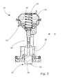
- a cross-section III - III of the mechanical coolant pump 10 of fig. 2 is shown.
- the shiftable valve plate 22 is driven by the pneumatic actuator 32 via a pneumatic membrane 34 and an actuator rod 36.
- the actuator rod 36 is axially in line with the valve plate 22 and perpendicular to the membrane 34.
- the membrane 34 is preloaded by a preload spring 37 into the closed position of the outlet valve 20.
- the preload spring 37 can be arranged inversely to preload the outlet valve 20 in the open position so that the construction is failsafe,
Landscapes
- Engineering & Computer Science (AREA)
- General Engineering & Computer Science (AREA)
- Mechanical Engineering (AREA)
- Chemical & Material Sciences (AREA)
- Combustion & Propulsion (AREA)
- Structures Of Non-Positive Displacement Pumps (AREA)
Abstract
Description
- The present invention refers to a mechanical coolant pump for an internal combustion engine with an impeller for pumping the coolant into an outlet channel, wherein the outlet channel comprises an outlet valve.
- A mechanical coolant is a coolant pump which is driven by the combustion engine, for example by using a driving belt driving a driving wheel of the pump. As long as the combustion engine is cold, only a minimum coolant flow is needed. Therefore, mechanical coolant pumps are used which are provided with an outlet valve for controlling the coolant circulation flow. As long as the combustion engine is cold, the outlet valve is closed so that the circulation of the lubricant is minimized, with the result that the combustion engine warming-up period is decreased.
- Usually, outlet valves are used in the form of a pivoting flap, whereby the pivoting flap is positioned in the lubricant outlet channel, The pivoting flap can be controlled to rotate the flap into an open or closed position, whereby the positions determine the coolant circulation flow. The arrangement of such a pivoting flap inside the lubricant outlet channel restrains the coolant flow even at the open position of the flap and induces a flow resistance. Furthermore, such pivoting flaps can jam as a result of abrasion, distortion and particles which in the lubricant that adhere at the flap and the recess for the flap.
- It is an object of the present invention to provide a mechanical coolant pump with an improved outlet valve.
- This object is solved with a mechanical coolant pump with the features of claim 1.
- The mechanical coolant pump for an internal combustion engine according to clam 1 comprises an impeller for pumping the coolant into an outlet channel which comprises an outlet valve. The outlet valve comprises a shiftable flat valve plate which is shiftable in a transversal plane of the outlet channel through a passing slit in the outlet channel wall.
- A shiftable flat valve plate in the outlet channel enables the control of the coolant flow to the combustion engine in order to bring the optimum coolant volume during a cold start phase. A control of the coolant flow in the cold start phase of the combustion engine enables a quicker warming-up and therefore an improved energy-efficiency of the combustion engine. The shiftability of the valve plate in a transversal plane of the outlet channel through a passing slit in the outlet channel wall allows using an actuator. An actuator has a relative low actuation force because the sliding friction between the plate and the plate guiding is low and a pressure of the coolant acting against the valve plate does not significantly effects the actuation force which is necessary to move the valve plate into the open or closed position. Therefore, the coolant flow is not restrained during the circulation of the coolant.
- According to a preferred embodiment of the invention, the valve plate is positioned in a fluid-tight valve plate housing in the open position and the valve plate housing extends radially from the outlet channel. A fluid-tight valve plate housing keeps the valve plate always inside the lubricant space so that the passing slit does not need to be sealed.
- Preferably, the valve plate housing is formed as a separate part of a main pump body. A separate installation of the valve plate housing to the main pump body improves the flexibility with respect to the form and material of the housing so that the valve plate housing can be made of a material different from the material of the pump main body.
- Alternatively, the valve plate housing is an integrated part of the main pump body. This construction allows faster and more cost-efficient production.
- The main pump body is preferably provided with the passing slit for the shiftable flat valve plate.
- According to a preferred embodiment of the invention, the main pump body is provided with guiding slits at the outlet channel for the shiftable flat valve plate, and the valve plate is guided in the guiding slits. This guiding slits provide an additional support of the valve plate against the pressure of the coolant flow which impacts permanently on the valve plate in the not opened position and ensures the transversal movability of the valve plate in the outlet channel.
- Preferably, the valve plate is driven by an actuator.
- According to a preferred embodiment of the invention, the actuator is directly connected to the valve plate housing, so that no gear or lever or other means are necessary to transform the actuator movement to the valve plate movement.
- Preferably, the valve plate is driven by a pneumatic actuator. The valve plate can also be driven by other actuators like electrical or thermostatic. The pneumatic energy can be tapped at different positions at the combustion engine so that the use of a pneumatic actuator is simple and cost-efficient.
- The pneumatic actuator is preferably provided with a membrane and an actuator rod perpendicular to the membrane, whereby the actuator rod is directly connected to and axially in line with the valve plate, so that no gear, lever etc. is necessary.
- The following is a detailed description of an embodiment of the invention with reference to the drawings, in which:
- fig. 1
- shows a perspective view of the mechanical coolant pump,
- fig. 2
- shows a longitudinal section of the mechanical coolant pump,
- fig. 3
- shows the cross-section of the mechanical coolant pump of
fig. 2 along line III - III, and - fig. 4
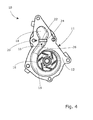
- shows a bottom view of the mechanical coolant pump.
- In
figure 1 , amechanical coolant pump 10 for an internal combustion engine is shown. Themechanical coolant pump 10 comprises amain pump body 11, whereby the main pump body is mounted directly to the engine block by aflange 12 or can have a cover plate which is not shown. - The pump
main body 11 holds arotatable impeller 18 which sucks the coolant axially and pumps the coolant radially outwardly into avolute 15. Theimpeller 18 is driven by the combustion engine by using a driving belt (not shown) which drives adriving wheel 38 of themechanical coolant pump 10. The coolant flows as a result of centrifugal forces from thevolute 15 into anoutlet channel 16 and through anoutlet valve 20 to an outlet opening 14. Theoutlet valve 20 is positioned at the terminal end of theoutlet channel 16. - The
outlet valve 20 comprises a shiftableflat valve plate 22 which is shiftable in a transversal plane of theoutlet channel 16 through apassing slit 24 of anoutlet channel wall 26. Thevalve plate 22 is in its open position positioned in a fluid-tightvalve plate housing 28 which extends radially from theoutlet channel 16 at thepassing slit 24. Theshiftable valve plate 22 is driven by apneumatic actuator 32, whereby thevalve plate 22 guides in guidingslits 30 and whereby the guidingslits 30 are provided in thechannel wall 26. - The
actuator 32 is provided with apneumatic membrane 34 in amembrane housing 35 and anactuator rod 36 perpendicular to themembrane 34, whereby theactuator rod 36 is axially in line with thevalve plate 22. Theactuator 32 is directly connected to thevalve plate housing 28. In the open position, thevalve plate 22 is completely positioned inside thevalve plate housing 28 so that the coolant flow is not restrained. As long as the combustion engine is cold, theoutlet valve 20 can be completely or partially closed by thepneumatic actuator 32. - In
fig. 2 a longitudinal section of themechanical coolant pump 10 is shown. Themechanical coolant pump 10 comprises a pumpmain body 11. At the top of the pumpmain body 11 thevalve plate housing 28 is positioned, whereby thevalve plate housing 28 extends radially from theoutlet channel 16 and perpendicular with respect to theflange 12 of themechanical coolant pump 10. - In
fig. 3 a cross-section III - III of themechanical coolant pump 10 offig. 2 is shown. Theshiftable valve plate 22 is driven by thepneumatic actuator 32 via apneumatic membrane 34 and anactuator rod 36. Theactuator rod 36 is axially in line with thevalve plate 22 and perpendicular to themembrane 34. Themembrane 34 is preloaded by apreload spring 37 into the closed position of theoutlet valve 20. Alternatively, thepreload spring 37 can be arranged inversely to preload theoutlet valve 20 in the open position so that the construction is failsafe,
Claims (10)
- Mechanical coolant pump (10) for an internal combustion engine, with an impeller (18) pumping the coolant into an outlet channel (16) comprising an outlet valve (20),
characterized in that
the outlet valve (20) comprises a shiftable flat valve plate (22) being shiftable in a transversal plane of the outlet channel (16) through a passing slit (24) of the outlet channel wall (26). - Mechanical coolant pump (10) of claim 1, wherein the valve plate (22) is positioned in a fluid-tight valve plate housing (28) in the open position and the valve plate housing (28) extends radially from the outlet channel (16).
- Mechanical coolant pump (10) of claim 2, wherein the valve plate housing (28) is formed as a separate part of a main pump body (10).
- Mechanical coolant pump (10) of claim 2, wherein the valve plate housing (28) is an integrated part of a main pump body (10).
- Mechanical coolant pump (10) of one of the preceding claims, wherein a main pump body (11) is provided with the passing slit (24) for the shiftable flat valve plate (22).
- Mechanical coolant pump (10) of one of the preceding claims, wherein a main pump body (11) is provided with guiding slits (30) for the shiftable flat valve plate (22), and the valve plate (22) is guided in the guiding slits (30).
- Mechanical coolant pump (10) of one of the preceding claims, wherein the valve plate (22) is driven by an actuator (32).
- Mechanical coolant pump (10) of claim 7, wherein the actuator (32) is directly connected to the valve plate housing (28).
- Mechanical coolant pump (10) of one of the claims 7 or 8, wherein the actuator (32) is a pneumatical, an electrical, a vacuum or a thermostatic actuator.
- Mechanical coolant pump (10) of claim 7, wherein the pneumatic actuator (32) is provided with a pneumatic membrane (34) and an actuator rod (36) perpendicular to the membrane (34), whereby the actuator rod (36) is in line with the valve plate (22).
Priority Applications (6)
| Application Number | Priority Date | Filing Date | Title |
|---|---|---|---|
| EP09170425A EP2299084A1 (en) | 2009-09-16 | 2009-09-16 | Mechanical coolant pump |
| CN201010241667.2A CN102022174B (en) | 2009-09-16 | 2010-07-29 | Mechanical coolant pump |
| BR112012005833A BR112012005833A2 (en) | 2009-09-16 | 2010-08-24 | mechanical cooling pump |
| PCT/EP2010/062336 WO2011032808A1 (en) | 2009-09-16 | 2010-08-24 | Mechanical coolant pump |
| JP2012529191A JP5864422B2 (en) | 2009-09-16 | 2010-08-24 | Mechanical coolant pump |
| US13/496,242 US8955471B2 (en) | 2009-09-16 | 2010-08-24 | Mechanical coolant pump |
Applications Claiming Priority (1)
| Application Number | Priority Date | Filing Date | Title |
|---|---|---|---|
| EP09170425A EP2299084A1 (en) | 2009-09-16 | 2009-09-16 | Mechanical coolant pump |
Publications (1)
| Publication Number | Publication Date |
|---|---|
| EP2299084A1 true EP2299084A1 (en) | 2011-03-23 |
Family
ID=41527690
Family Applications (1)
| Application Number | Title | Priority Date | Filing Date |
|---|---|---|---|
| EP09170425A Withdrawn EP2299084A1 (en) | 2009-09-16 | 2009-09-16 | Mechanical coolant pump |
Country Status (6)
| Country | Link |
|---|---|
| US (1) | US8955471B2 (en) |
| EP (1) | EP2299084A1 (en) |
| JP (1) | JP5864422B2 (en) |
| CN (1) | CN102022174B (en) |
| BR (1) | BR112012005833A2 (en) |
| WO (1) | WO2011032808A1 (en) |
Cited By (5)
| Publication number | Priority date | Publication date | Assignee | Title |
|---|---|---|---|---|
| ITMI20111379A1 (en) * | 2011-07-25 | 2013-01-26 | Metelli S P A | PNEUMATIC COOLING PUMP |
| WO2013120542A1 (en) * | 2012-02-14 | 2013-08-22 | Pierburg Pump Technology Gmbh | Mechanical coolant pump |
| WO2012141667A3 (en) * | 2011-04-15 | 2013-11-14 | Faruk Unluaslan | A switching system for blocking the coolant circulation for water cooled internal combustion engine |
| WO2014060041A1 (en) * | 2012-10-19 | 2014-04-24 | Pierburg Pump Technology Gmbh | Mechanical coolant pump |
| WO2016034159A1 (en) * | 2014-09-05 | 2016-03-10 | Nidec Gpm Gmbh | Device for regulating the pump pressure of centrifugal pumps |
Families Citing this family (8)
| Publication number | Priority date | Publication date | Assignee | Title |
|---|---|---|---|---|
| ITBS20120165A1 (en) * | 2012-11-27 | 2014-05-28 | Ind Saleri Italo Spa | VALVE ASSEMBLY WITH IMPROVED SEALING |
| ITBS20130149A1 (en) * | 2013-10-22 | 2015-04-23 | Ind Saleri Italo Spa | REMOVABLE VALVE GROUP WITH IMPROVED SHUTTER |
| DE102015106671A1 (en) * | 2015-04-29 | 2016-11-03 | Dr. Ing. H.C. F. Porsche Aktiengesellschaft | pump |
| USD775235S1 (en) * | 2015-08-31 | 2016-12-27 | Brent W. Huckey | Water pump mounting plate |
| USD816120S1 (en) * | 2015-08-31 | 2018-04-24 | Brent W. Huckey | Pair of water pump adaptor plates |
| DE102015119092B4 (en) * | 2015-11-06 | 2019-03-21 | Pierburg Gmbh | Method for controlling a mechanically controllable coolant pump for an internal combustion engine |
| CN108496011B (en) * | 2016-01-22 | 2021-04-13 | 利滕斯汽车合伙公司 | Pump with variable flow diverter forming volute |
| CN116146730B (en) * | 2023-02-01 | 2023-06-27 | 浙江三胜仪表有限公司 | Pneumatic film regulating valve |
Citations (9)
| Publication number | Priority date | Publication date | Assignee | Title |
|---|---|---|---|---|
| US4479670A (en) * | 1980-02-19 | 1984-10-30 | Ranco Incorporated | Water flow control valve |
| DE4033261A1 (en) | 1990-10-19 | 1992-04-23 | Freudenberg Carl Fa | Cooling system for combustion engine - has control unit to regulate mass flow |
| JPH0586970A (en) * | 1991-09-20 | 1993-04-06 | Nissan Motor Co Ltd | Cooling device for engine |
| US5551384A (en) * | 1995-05-23 | 1996-09-03 | Hollis; Thomas J. | System for heating temperature control fluid using the engine exhaust manifold |
| DE19540591A1 (en) * | 1995-10-31 | 1997-05-07 | Behr Gmbh & Co | Volume flow regulating process for vehicle coolant circuit |
| DE10028280A1 (en) * | 1999-07-23 | 2001-04-05 | Toyoda Automatic Loom Works | Pump and heater |
| WO2003036145A1 (en) * | 2001-10-22 | 2003-05-01 | Cooper Technology Services, Llc | Electric engine coolant control valve |
| EP1312803A2 (en) * | 2001-11-15 | 2003-05-21 | Wilo Ag | Automatic pump |
| EP1950387A1 (en) * | 2007-01-29 | 2008-07-30 | Ford Global Technologies, LLC | Thermostat valve |
Family Cites Families (1)
| Publication number | Priority date | Publication date | Assignee | Title |
|---|---|---|---|---|
| JPH0191031U (en) * | 1987-12-07 | 1989-06-15 |
-
2009
- 2009-09-16 EP EP09170425A patent/EP2299084A1/en not_active Withdrawn
-
2010
- 2010-07-29 CN CN201010241667.2A patent/CN102022174B/en not_active Expired - Fee Related
- 2010-08-24 JP JP2012529191A patent/JP5864422B2/en not_active Expired - Fee Related
- 2010-08-24 US US13/496,242 patent/US8955471B2/en not_active Expired - Fee Related
- 2010-08-24 BR BR112012005833A patent/BR112012005833A2/en not_active IP Right Cessation
- 2010-08-24 WO PCT/EP2010/062336 patent/WO2011032808A1/en not_active Ceased
Patent Citations (9)
| Publication number | Priority date | Publication date | Assignee | Title |
|---|---|---|---|---|
| US4479670A (en) * | 1980-02-19 | 1984-10-30 | Ranco Incorporated | Water flow control valve |
| DE4033261A1 (en) | 1990-10-19 | 1992-04-23 | Freudenberg Carl Fa | Cooling system for combustion engine - has control unit to regulate mass flow |
| JPH0586970A (en) * | 1991-09-20 | 1993-04-06 | Nissan Motor Co Ltd | Cooling device for engine |
| US5551384A (en) * | 1995-05-23 | 1996-09-03 | Hollis; Thomas J. | System for heating temperature control fluid using the engine exhaust manifold |
| DE19540591A1 (en) * | 1995-10-31 | 1997-05-07 | Behr Gmbh & Co | Volume flow regulating process for vehicle coolant circuit |
| DE10028280A1 (en) * | 1999-07-23 | 2001-04-05 | Toyoda Automatic Loom Works | Pump and heater |
| WO2003036145A1 (en) * | 2001-10-22 | 2003-05-01 | Cooper Technology Services, Llc | Electric engine coolant control valve |
| EP1312803A2 (en) * | 2001-11-15 | 2003-05-21 | Wilo Ag | Automatic pump |
| EP1950387A1 (en) * | 2007-01-29 | 2008-07-30 | Ford Global Technologies, LLC | Thermostat valve |
Cited By (11)
| Publication number | Priority date | Publication date | Assignee | Title |
|---|---|---|---|---|
| WO2012141667A3 (en) * | 2011-04-15 | 2013-11-14 | Faruk Unluaslan | A switching system for blocking the coolant circulation for water cooled internal combustion engine |
| ITMI20111379A1 (en) * | 2011-07-25 | 2013-01-26 | Metelli S P A | PNEUMATIC COOLING PUMP |
| EP2551484A1 (en) * | 2011-07-25 | 2013-01-30 | METELLI S.p.A. | Pneumatically-operated cooling pump |
| WO2013120542A1 (en) * | 2012-02-14 | 2013-08-22 | Pierburg Pump Technology Gmbh | Mechanical coolant pump |
| WO2013120514A1 (en) * | 2012-02-14 | 2013-08-22 | Pierburg Pump Technology Gmbh | Mechanical coolant pump |
| US9689393B2 (en) | 2012-02-14 | 2017-06-27 | Pierburg Pump Technology Gmbh | Mechanical coolant pump |
| US9689392B2 (en) | 2012-02-14 | 2017-06-27 | Pierburg Pump Technology Gmbh | Mechanical coolant pump |
| US9726178B2 (en) | 2012-02-14 | 2017-08-08 | Pierburg Pump Technology Gmbh | Mechanical coolant pump |
| WO2014060041A1 (en) * | 2012-10-19 | 2014-04-24 | Pierburg Pump Technology Gmbh | Mechanical coolant pump |
| US9574485B2 (en) | 2012-10-19 | 2017-02-21 | Pierburg Pump Technology Gmbh | Mechanical coolant pump |
| WO2016034159A1 (en) * | 2014-09-05 | 2016-03-10 | Nidec Gpm Gmbh | Device for regulating the pump pressure of centrifugal pumps |
Also Published As
| Publication number | Publication date |
|---|---|
| JP2013504717A (en) | 2013-02-07 |
| BR112012005833A2 (en) | 2017-05-30 |
| US20120192816A1 (en) | 2012-08-02 |
| WO2011032808A1 (en) | 2011-03-24 |
| CN102022174A (en) | 2011-04-20 |
| US8955471B2 (en) | 2015-02-17 |
| CN102022174B (en) | 2015-06-03 |
| JP5864422B2 (en) | 2016-02-17 |
Similar Documents
| Publication | Publication Date | Title |
|---|---|---|
| US8955471B2 (en) | Mechanical coolant pump | |
| JP6679718B2 (en) | Coolant pump for internal combustion engine | |
| EP2536928B1 (en) | Mechanical coolant pump | |
| JP6648281B2 (en) | Pump having a control system including a control system for managing the supply of pressurized lubricant | |
| US20140144407A1 (en) | Sector gear with integrated bushing | |
| KR20130137640A (en) | Control valve | |
| CN104755824A (en) | Extractable valve group with improved obturator | |
| WO2016046682A1 (en) | Valve group with axially movable shutter | |
| EP1712792A3 (en) | Control valve for variable capacity compressors | |
| KR101655645B1 (en) | Active intake variable valve and operation method thereof | |
| EP1616118A1 (en) | Stepper motor driven fluid valve | |
| EP2909456B1 (en) | Mechanical coolant pump | |
| EP4067665B1 (en) | Variable coolant pumps | |
| US20120291723A1 (en) | Actuating mechanism for a regulated coolant pump | |
| CN104271932B (en) | Mixing valve of an internal combustion engine | |
| US20140003913A1 (en) | Infinitely adjustable coolant pump | |
| US7318577B2 (en) | Motor-operated valve assembly | |
| US20140037432A1 (en) | Controllable coolant pump | |
| US8967982B2 (en) | Mechanical coolant pump | |
| EP2236924A3 (en) | Staging valve arrangement and valve for use therein | |
| CN106460681A (en) | Fluid flow valve | |
| CN222229618U (en) | Multifunctional solenoid valve | |
| KR101189357B1 (en) | Variable oil pump being able to control oil flux of vehicle | |
| EP1850042A3 (en) | Angled poppet valve manual override mechanism | |
| US20110286862A1 (en) | Pump for a lubricating system of a combustion engine |
Legal Events
| Date | Code | Title | Description |
|---|---|---|---|
| PUAI | Public reference made under article 153(3) epc to a published international application that has entered the european phase |
Free format text: ORIGINAL CODE: 0009012 |
|
| AK | Designated contracting states |
Kind code of ref document: A1 Designated state(s): AT BE BG CH CY CZ DE DK EE ES FI FR GB GR HR HU IE IS IT LI LT LU LV MC MK MT NL NO PL PT RO SE SI SK SM TR |
|
| AX | Request for extension of the european patent |
Extension state: AL BA RS |
|
| 17P | Request for examination filed |
Effective date: 20110303 |
|
| 17Q | First examination report despatched |
Effective date: 20110404 |
|
| STAA | Information on the status of an ep patent application or granted ep patent |
Free format text: STATUS: EXAMINATION IS IN PROGRESS |
|
| STAA | Information on the status of an ep patent application or granted ep patent |
Free format text: STATUS: THE APPLICATION IS DEEMED TO BE WITHDRAWN |
|
| 18D | Application deemed to be withdrawn |
Effective date: 20161018 |