EP2299079A1 - Filter insert - Google Patents
Filter insert Download PDFInfo
- Publication number
- EP2299079A1 EP2299079A1 EP10173662A EP10173662A EP2299079A1 EP 2299079 A1 EP2299079 A1 EP 2299079A1 EP 10173662 A EP10173662 A EP 10173662A EP 10173662 A EP10173662 A EP 10173662A EP 2299079 A1 EP2299079 A1 EP 2299079A1
- Authority
- EP
- European Patent Office
- Prior art keywords
- filter
- insert
- tank
- urea
- inlet
- Prior art date
- Legal status (The legal status is an assumption and is not a legal conclusion. Google has not performed a legal analysis and makes no representation as to the accuracy of the status listed.)
- Granted
Links
- 239000004202 carbamide Substances 0.000 claims abstract description 38
- XSQUKJJJFZCRTK-UHFFFAOYSA-N Urea Chemical compound NC(N)=O XSQUKJJJFZCRTK-UHFFFAOYSA-N 0.000 claims abstract description 37
- 238000010438 heat treatment Methods 0.000 claims abstract description 30
- 238000001914 filtration Methods 0.000 claims abstract description 8
- 239000007788 liquid Substances 0.000 claims abstract description 7
- 229910052751 metal Inorganic materials 0.000 claims abstract description 4
- 239000002184 metal Substances 0.000 claims abstract description 4
- 229910052782 aluminium Inorganic materials 0.000 claims abstract description 3
- XAGFODPZIPBFFR-UHFFFAOYSA-N aluminium Chemical compound [Al] XAGFODPZIPBFFR-UHFFFAOYSA-N 0.000 claims abstract description 3
- 238000003780 insertion Methods 0.000 claims description 5
- 230000037431 insertion Effects 0.000 claims description 5
- 239000004020 conductor Substances 0.000 claims description 4
- 239000006223 plastic coating Substances 0.000 claims description 3
- 239000000243 solution Substances 0.000 description 12
- MWUXSHHQAYIFBG-UHFFFAOYSA-N Nitric oxide Chemical compound O=[N] MWUXSHHQAYIFBG-UHFFFAOYSA-N 0.000 description 9
- QGZKDVFQNNGYKY-UHFFFAOYSA-N Ammonia Chemical compound N QGZKDVFQNNGYKY-UHFFFAOYSA-N 0.000 description 6
- 229910021529 ammonia Inorganic materials 0.000 description 3
- 238000006243 chemical reaction Methods 0.000 description 3
- 230000001419 dependent effect Effects 0.000 description 3
- 230000008014 freezing Effects 0.000 description 3
- 238000007710 freezing Methods 0.000 description 3
- XLYOFNOQVPJJNP-UHFFFAOYSA-N water Substances O XLYOFNOQVPJJNP-UHFFFAOYSA-N 0.000 description 3
- CURLTUGMZLYLDI-UHFFFAOYSA-N Carbon dioxide Chemical compound O=C=O CURLTUGMZLYLDI-UHFFFAOYSA-N 0.000 description 2
- 238000009413 insulation Methods 0.000 description 2
- 229910002092 carbon dioxide Inorganic materials 0.000 description 1
- 239000001569 carbon dioxide Substances 0.000 description 1
- 239000003054 catalyst Substances 0.000 description 1
- 238000006555 catalytic reaction Methods 0.000 description 1
- 238000010790 dilution Methods 0.000 description 1
- 239000012895 dilution Substances 0.000 description 1
- 239000003344 environmental pollutant Substances 0.000 description 1
- 239000012530 fluid Substances 0.000 description 1
- 239000007789 gas Substances 0.000 description 1
- 238000006460 hydrolysis reaction Methods 0.000 description 1
- 230000010354 integration Effects 0.000 description 1
- 238000002955 isolation Methods 0.000 description 1
- 238000000034 method Methods 0.000 description 1
- 231100000719 pollutant Toxicity 0.000 description 1
- 238000007493 shaping process Methods 0.000 description 1
- 238000009827 uniform distribution Methods 0.000 description 1
- 150000003672 ureas Chemical class 0.000 description 1
- 238000003466 welding Methods 0.000 description 1
Images

Classifications
-
- F—MECHANICAL ENGINEERING; LIGHTING; HEATING; WEAPONS; BLASTING
- F01—MACHINES OR ENGINES IN GENERAL; ENGINE PLANTS IN GENERAL; STEAM ENGINES
- F01N—GAS-FLOW SILENCERS OR EXHAUST APPARATUS FOR MACHINES OR ENGINES IN GENERAL; GAS-FLOW SILENCERS OR EXHAUST APPARATUS FOR INTERNAL COMBUSTION ENGINES
- F01N3/00—Exhaust or silencing apparatus having means for purifying, rendering innocuous, or otherwise treating exhaust
- F01N3/08—Exhaust or silencing apparatus having means for purifying, rendering innocuous, or otherwise treating exhaust for rendering innocuous
- F01N3/10—Exhaust or silencing apparatus having means for purifying, rendering innocuous, or otherwise treating exhaust for rendering innocuous by thermal or catalytic conversion of noxious components of exhaust
- F01N3/18—Exhaust or silencing apparatus having means for purifying, rendering innocuous, or otherwise treating exhaust for rendering innocuous by thermal or catalytic conversion of noxious components of exhaust characterised by methods of operation; Control
- F01N3/20—Exhaust or silencing apparatus having means for purifying, rendering innocuous, or otherwise treating exhaust for rendering innocuous by thermal or catalytic conversion of noxious components of exhaust characterised by methods of operation; Control specially adapted for catalytic conversion ; Methods of operation or control of catalytic converters
- F01N3/2066—Selective catalytic reduction [SCR]
-
- B—PERFORMING OPERATIONS; TRANSPORTING
- B01—PHYSICAL OR CHEMICAL PROCESSES OR APPARATUS IN GENERAL
- B01D—SEPARATION
- B01D35/00—Filtering devices having features not specifically covered by groups B01D24/00 - B01D33/00, or for applications not specifically covered by groups B01D24/00 - B01D33/00; Auxiliary devices for filtration; Filter housing constructions
- B01D35/18—Heating or cooling the filters
-
- B—PERFORMING OPERATIONS; TRANSPORTING
- B01—PHYSICAL OR CHEMICAL PROCESSES OR APPARATUS IN GENERAL
- B01D—SEPARATION
- B01D46/00—Filters or filtering processes specially modified for separating dispersed particles from gases or vapours
- B01D46/42—Auxiliary equipment or operation thereof
- B01D46/4263—Means for active heating or cooling
-
- B—PERFORMING OPERATIONS; TRANSPORTING
- B01—PHYSICAL OR CHEMICAL PROCESSES OR APPARATUS IN GENERAL
- B01D—SEPARATION
- B01D53/00—Separation of gases or vapours; Recovering vapours of volatile solvents from gases; Chemical or biological purification of waste gases, e.g. engine exhaust gases, smoke, fumes, flue gases, aerosols
- B01D53/005—Separation of gases or vapours; Recovering vapours of volatile solvents from gases; Chemical or biological purification of waste gases, e.g. engine exhaust gases, smoke, fumes, flue gases, aerosols by heat treatment
-
- F—MECHANICAL ENGINEERING; LIGHTING; HEATING; WEAPONS; BLASTING
- F01—MACHINES OR ENGINES IN GENERAL; ENGINE PLANTS IN GENERAL; STEAM ENGINES
- F01N—GAS-FLOW SILENCERS OR EXHAUST APPARATUS FOR MACHINES OR ENGINES IN GENERAL; GAS-FLOW SILENCERS OR EXHAUST APPARATUS FOR INTERNAL COMBUSTION ENGINES
- F01N2610/00—Adding substances to exhaust gases
- F01N2610/02—Adding substances to exhaust gases the substance being ammonia or urea
-
- F—MECHANICAL ENGINEERING; LIGHTING; HEATING; WEAPONS; BLASTING
- F01—MACHINES OR ENGINES IN GENERAL; ENGINE PLANTS IN GENERAL; STEAM ENGINES
- F01N—GAS-FLOW SILENCERS OR EXHAUST APPARATUS FOR MACHINES OR ENGINES IN GENERAL; GAS-FLOW SILENCERS OR EXHAUST APPARATUS FOR INTERNAL COMBUSTION ENGINES
- F01N2610/00—Adding substances to exhaust gases
- F01N2610/10—Adding substances to exhaust gases the substance being heated, e.g. by heating tank or supply line of the added substance
-
- F—MECHANICAL ENGINEERING; LIGHTING; HEATING; WEAPONS; BLASTING
- F01—MACHINES OR ENGINES IN GENERAL; ENGINE PLANTS IN GENERAL; STEAM ENGINES
- F01N—GAS-FLOW SILENCERS OR EXHAUST APPARATUS FOR MACHINES OR ENGINES IN GENERAL; GAS-FLOW SILENCERS OR EXHAUST APPARATUS FOR INTERNAL COMBUSTION ENGINES
- F01N2610/00—Adding substances to exhaust gases
- F01N2610/14—Arrangements for the supply of substances, e.g. conduits
- F01N2610/1406—Storage means for substances, e.g. tanks or reservoirs
-
- F—MECHANICAL ENGINEERING; LIGHTING; HEATING; WEAPONS; BLASTING
- F01—MACHINES OR ENGINES IN GENERAL; ENGINE PLANTS IN GENERAL; STEAM ENGINES
- F01N—GAS-FLOW SILENCERS OR EXHAUST APPARATUS FOR MACHINES OR ENGINES IN GENERAL; GAS-FLOW SILENCERS OR EXHAUST APPARATUS FOR INTERNAL COMBUSTION ENGINES
- F01N2610/00—Adding substances to exhaust gases
- F01N2610/14—Arrangements for the supply of substances, e.g. conduits
- F01N2610/1426—Filtration means
-
- Y—GENERAL TAGGING OF NEW TECHNOLOGICAL DEVELOPMENTS; GENERAL TAGGING OF CROSS-SECTIONAL TECHNOLOGIES SPANNING OVER SEVERAL SECTIONS OF THE IPC; TECHNICAL SUBJECTS COVERED BY FORMER USPC CROSS-REFERENCE ART COLLECTIONS [XRACs] AND DIGESTS
- Y02—TECHNOLOGIES OR APPLICATIONS FOR MITIGATION OR ADAPTATION AGAINST CLIMATE CHANGE
- Y02T—CLIMATE CHANGE MITIGATION TECHNOLOGIES RELATED TO TRANSPORTATION
- Y02T10/00—Road transport of goods or passengers
- Y02T10/10—Internal combustion engine [ICE] based vehicles
- Y02T10/12—Improving ICE efficiencies
Definitions
- the present invention relates to a filter insert for insertion into a tank, in particular into a urea tank.
- the invention also relates to an insert with such a filter cartridge and a tank with such insert or filter cartridge.
- the so-called SCR process is nowadays used, which contributes to reducing the nitrogen oxide emission in diesel vehicles.
- the ammonia required for the SCR reaction is not used directly, that is in pure form, but usually in the form of an aqueous urea solution.
- Ammonia and carbon dioxide are produced from this urea solution by means of a hydrolysis reaction, the ammonia thus produced being able to react with a special SCR catalyst at the appropriate temperature with the nitrogen oxides of the exhaust gas.
- the consumption of urea solution is dependent on the raw emission and in particular also a load condition of the motor vehicle, so that always a certain volume of urea solution must be carried in a designated tank.
- the urea solution contains water for dilution, at extreme temperatures there is a risk that the aqueous urea solution in the tank provided freezes and as a result the SCR reaction necessary for nitrogen oxide reduction can no longer take place. It is therefore essential for reliable operation and compliance with the statutory emission standards that the freezing of the urea solution is reliably prevented. Since filtering devices for filtering the aqueous urea solution are usually provided in the known urea tanks, and these may tend to clog at low temperatures, it is also necessary to ensure that such Filter devices work smoothly and flawlessly at all temperatures occurring.
- the present invention is primarily concerned with the problem of providing a filter cartridge for insertion into a tank, in particular a UREA tank, which is functional independently of normally exiting external temperatures.
- the present invention is based on the general idea to heat a filter insert for insertion into a tank, in particular in a UREA tank (urea tank) over a large area, but in particular in the region of an inlet and an outlet and a filter device, and thus even at low outside temperatures to ensure reliable operation of the filter cartridge.
- the filter insert according to the invention in this case has a housing with at least one inlet and at least one outlet, wherein between these at least one filter device for filtering the liquid stored in the tank, in particular the urea, is arranged.
- the heating device according to the invention heats the housing of the filter insert, at least in the region of the inlet, the outlet and the filter device, so that the full functionality of the filter element can be ensured even at low temperatures.
- heating devices have been known which have heated the urea in the tank, but not the outlet of the filter insert, so that at low temperatures the urea located in the region of the outlet is frozen, which likewise directly leads to inoperability of the filter insert. Due to the inventive design the filter insert, in which both the inlet, the outlet and the intermediate filter device can be heated, it is possible to ensure full functionality of the filter element at low temperatures.
- the heating device has at least one electrical heating element, in particular a PTC element.
- PTC positive temperature coefficient
- Such PTC elements usually have current-conducting materials which can conduct the current better at lower temperatures than at high temperatures. Their electrical resistance increases accordingly with increasing temperature.
- PTC elements can be preset to corresponding temperatures from which heating should take place. Thus, when the actual temperature drops below the preset temperature, the heater begins to heat the liquid contents in the filter cartridge, whereas if the actual temperature in the filter cartridge is exceeded above the predefined PTC temperature, the heater will set heating of the fluid in the filter cartridge.
- Such planteleitaires thereby enable a large-area and in particular also targeted heating of the filter cartridge and can also be molded with plastic, in particular be injected in a respective wall portion of the housing of the filter cartridge.
- Such heat-conducting body are usually made of a good heat-conducting material, such as metal and can additionally due to their higher stiffness be used to support the shaping and stiffening of the filter cartridge. By appropriate design of the heat-conducting body, a targeted heating of the filter insert can be achieved.
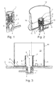
- the filter insert 1 for insertion into a tank 2, in particular in a UREA tank 2 (see. Fig. 3 ), that is in a urea tank, a housing 5 having at least one inlet 3 and at least one outlet 4.
- the filter insert 1 according to the invention has a filter device 6 (cf. FIGS. 2 and 3 ) for filtering the stored liquid in the tank 2, such as urea, on. Since the urea for carrying out an SCR reaction (selective catalytic reaction) is diluted with water, the functionality of the filter cartridge 1 must be able to be guaranteed even at low temperatures, which may under certain circumstances freeze the water content in the urea.
- the filter element 1 has a heating device 7, which heats the housing 5 of the filter insert 1 at least in the region of the inlet 3, the outlet 4 and the filter device 6.
- the heating device 7 has at least one electrical heating element 8, which is designed, for example, as a so-called PTC element (positive temperature coefficient).
- This at least one heating element 8 is connected heat-transmittingly with heat-conducting bodies 9 which extend into the housing 5 of the filter insert 1 at least in the region of the at least one inlet 3 of the at least one outlet 4 and the filter device 6.
- the heat-conducting body 9 are encapsulated with plastic and in particular injected into a respective wall region of the housing 5 of the filter cartridge 1.
- the heat-conducting body 9 consist of a good heat-conducting material, such as metal and in particular aluminum, and thereby ensure a rapid and uniform distribution of the heat generated by the heating element 8 of the heater 7.
- filter insert 1 shown also an integral part of a used in a tank 2 Insert 10 may form, in which case the heater 7 additionally wall portions 11 of the insert 10, in particular in the region of an inlet 12 of the insert 10, heated.
- the heater 7 additionally wall portions 11 of the insert 10, in particular in the region of an inlet 12 of the insert 10, heated.
- filter element 1 it is possible, in comparison to according to the Fig. 1 shown filter element 1 to apply a larger volume of urea with heating energy.
- a plastic coating of the heat-conducting body 9 with respect to an interior 13 of the insert 10 is smaller than outward, so that radiated from the heat-conducting 9 heating energy predominantly on the in-use 10 liquid, such as the urea located there , is transmitted, whereas the outwardly comparatively thick plastic coating provides for a corresponding insulation.
- FIG. 3 When presented in the Fig. 3 is shown how the use 10 of the Fig. 2 is inserted into a wall of the tank 2, wherein the tightness between the tank 2 and the insert 10 is usually made by welding.
- the tightness between the tank 2 and the insert 10 is usually made by welding.
- filter insert 1 is inserted directly into a wall of the tank 2, and in particular there is welded.
- the insert 1 according to the invention or of the insert 10 provides a comparatively large heating surface in the form of the existing heat conducting body 9, but this requires only little additional space requirement due to its integration into the wall regions of the housing 5 and the insert 10.
- the filter device 6 can be heated over a large area and thus reliably, since the heat-conducting body 9 surrounds it over a large area.
- the filter device 6 can have a ring filter element.
- the outlet 4 and optionally also an inlet 12 of the insert 10 is heated, as well as an interior 13 of the insert 10, whereby a freezing of the aqueous urea solution is to be feared neither in the region of the inlet 3, nor in the region of the filter device 6 or the outlet 4.
- a partial freezing of urea for example in the region of the outlet 4 or the inlet 3 or the filter device 6, which would also lead to a complete inoperability.
- the Fig. 4 3 shows a urea filter device (14) with a housing (5) having at least one inlet (3) and at least one outlet (4), with a filter element (15) for filtering urea and with a heating device (7) which encloses the housing (FIG. 5) of the filter insert (1) at least in the region of the at least one inlet (3), the outlet (4) and the filter element (15) heated.
- the urea filter device (14) can be installed externally to a UREA (urea) tank 2.
- the invention must not be limited to a urea filter device (14), but can in principle be transferred to other liquid filter devices.
Abstract
Description
Die vorliegende Erfindung betrifft einen Filtereinsatz zum Einsetzen in einen Tank, insbesondere in einen Harnstofftank. Die Erfindung betrifft außerdem einen Einsatz mit einem derartigen Filtereinsatz sowie einen Tank mit einem derartigen Einsatz bzw. Filtereinsatz.The present invention relates to a filter insert for insertion into a tank, in particular into a urea tank. The invention also relates to an insert with such a filter cartridge and a tank with such insert or filter cartridge.
Um einen Schadstoffausstoß, insbesondere bei Kraftfahrzeugen, nachhaltig senken zu können, wird heutzutage das sogenannte SCR-Verfahren angewendet, welches dazu beiträgt die Stickoxidemission bei Dieselkraftfahrzeugen zu senken. Der für die SCR-Reaktion benötigt Ammoniak wird nicht direkt, das heißt in reiner Form verwendet, sondern üblicherweise in Form einer wässrigen Harnstofflösung. Aus dieser Harnstofflösung entstehen durch eine Hydrolysereaktion Ammoniak und Kohlendioxid, wobei der so erzeugte Ammoniak einem speziellen SCR-Katalysator bei entsprechender Temperatur mit den Stickoxiden des Abgases reagieren kann. Der Verbrauch an Harnstofflösung ist dabei abhängig von der Rohemission und insbesondere auch eines Belastungszustandes des Kraftfahrzeuges ist, so dass stets ein gewisses Volumen an Harnstofflösung in einem dafür vorgesehenen Tank mitgeführt werden muss. Da die Harnstofflösung zur Verdünnung Wasser beinhaltet, kann bei extremen Temperaturen die Gefahr bestehen, dass die wässrige Harnstofflösung im dafür vorgesehenen Tank gefriert und dadurch die zur Stickoxidsenkung notwendige SCR-Reaktion nicht mehr ablaufen kann. Es ist somit zum zuverlässigen Betrieb und zur Einhaltung der gesetzlich festgeschriebenen Abgasnormen unbedingt erforderlich, dass das Gefrieren der Harnstofflösung zuverlässig verhindert wird. Da in den bekannten Harnstofftanks üblicherweise auch Filtereinrichtungen zur Filtration der wässrigen Harnstofflösung vorgesehen sind, und diese bei geringen Temperaturen zum Verstopfen neigen können, ist zudem dafür Sorge zu tragen, dass auch derartige Filtereinrichtungen bei allen auftretenden Temperaturen problemlos und einwandfrei arbeiten.In order to be able to sustainably reduce pollutant emissions, in particular in motor vehicles, the so-called SCR process is nowadays used, which contributes to reducing the nitrogen oxide emission in diesel vehicles. The ammonia required for the SCR reaction is not used directly, that is in pure form, but usually in the form of an aqueous urea solution. Ammonia and carbon dioxide are produced from this urea solution by means of a hydrolysis reaction, the ammonia thus produced being able to react with a special SCR catalyst at the appropriate temperature with the nitrogen oxides of the exhaust gas. The consumption of urea solution is dependent on the raw emission and in particular also a load condition of the motor vehicle, so that always a certain volume of urea solution must be carried in a designated tank. Since the urea solution contains water for dilution, at extreme temperatures there is a risk that the aqueous urea solution in the tank provided freezes and as a result the SCR reaction necessary for nitrogen oxide reduction can no longer take place. It is therefore essential for reliable operation and compliance with the statutory emission standards that the freezing of the urea solution is reliably prevented. Since filtering devices for filtering the aqueous urea solution are usually provided in the known urea tanks, and these may tend to clog at low temperatures, it is also necessary to ensure that such Filter devices work smoothly and flawlessly at all temperatures occurring.
Die vorliegende Erfindung beschäftigt sich primär mit dem Problem, einen Filtereinsatz zum Einsetzen in einen Tank, insbesondere in einen UREA-Tank, anzugeben, der unabhängig von üblicherweise austretenden Außentemperaturen funktionsfähig ist.The present invention is primarily concerned with the problem of providing a filter cartridge for insertion into a tank, in particular a UREA tank, which is functional independently of normally exiting external temperatures.
Dieses Problem wird erfindungsgemäß durch die Gegenstände der unabhängigen Ansprüche gelöst. Vorteilhafte Ausführungsformen sind Gegenstand der abhängigen Ansprüche.This problem is solved according to the invention by the subject matters of the independent claims. Advantageous embodiments are the subject of the dependent claims.
Die vorliegende Erfindung beruht auf dem allgemeinen Gedanken, einen Filtereinsatz zum Einsetzen in einen Tank, insbesondere in einen UREA-Tank (Harnstofftank) großflächig, insbesondere jedoch im Bereich eines Einlasses und eines Auslasses sowie einer Filtereinrichtung zu beheizen, und dadurch auch bei geringen Außentemperaturen eine zuverlässige Funktionsweise des Filtereinsatzes zu gewährleisten. Der erfindungsgemäße Filtereinsatz weist dabei ein Gehäuse mit zumindest einem Einlass und zumindest einem Auslass auf, wobei zwischen diesen zumindest eine Filtereinrichtung zum Filtern der im Tank gespeicherten Flüssigkeit, insbesondere des Harnstoffs, angeordnet ist. Die erfindungsgemäße Heizeinrichtung beheizt dabei das Gehäuse des Filtereinsatzes und zwar zumindest im Bereich des Einlasses, des Auslasses und der Filtereinrichtung, sodass selbst bei geringen Temperaturen die volle Funktionsfähigkeit des Filtereinsatzes gewährleistet werden kann. Bisher waren beispielsweise Heizeinrichtungen bekannt, die den Harnstoff im Tank, nicht jedoch den Auslass des Filtereinsatzes beheizt haben, so dass bei geringen Temperaturen der sich im Bereich des Auslass befindliche Harnstoff gefroren ist, was ebenfalls unmittelbar zur Funktionsuntüchtigkeit des Filtereinsatzes führte. Durch die erfindungsgemäße Ausbildung des Filtereinsatzes, bei welchem sowohl der Einlass, der Auslass sowie die dazwischen liegende Filtereinrichtung beheizt werden können, ist es möglich, die volle Funktionsfähigkeit des Filtereinsatzes bei tiefen Temperaturen zu gewährleisten.The present invention is based on the general idea to heat a filter insert for insertion into a tank, in particular in a UREA tank (urea tank) over a large area, but in particular in the region of an inlet and an outlet and a filter device, and thus even at low outside temperatures to ensure reliable operation of the filter cartridge. The filter insert according to the invention in this case has a housing with at least one inlet and at least one outlet, wherein between these at least one filter device for filtering the liquid stored in the tank, in particular the urea, is arranged. The heating device according to the invention heats the housing of the filter insert, at least in the region of the inlet, the outlet and the filter device, so that the full functionality of the filter element can be ensured even at low temperatures. Hitherto, for example, heating devices have been known which have heated the urea in the tank, but not the outlet of the filter insert, so that at low temperatures the urea located in the region of the outlet is frozen, which likewise directly leads to inoperability of the filter insert. Due to the inventive design the filter insert, in which both the inlet, the outlet and the intermediate filter device can be heated, it is possible to ensure full functionality of the filter element at low temperatures.
Bei einer vorteilhaften Weiterbildung der erfindungsgemäßen Lösung, weist die Heizeinrichtung zumindest ein elektrisches Heizelement, insbesondere ein PTC-Element, auf. Derartige PTC-Heizelemente (positive temperature coefficient) besitzen üblicherweise stromleitende Materialien, die bei tieferen Temperaturen den Strom besser leiten können als bei hohen Temperaturen. Ihr elektrischer Widerstand vergrößert sich demnach bei steigender Temperatur. Derartige PTC-Elemente können dabei auf entsprechende Temperaturen voreingestellt werden, ab denen ein Beheizen erfolgen soll. Sinkt somit die tatsächliche Temperatur unter die voreingestellte Temperatur ab, beginnt die Heizeinrichtung mit dem Aufheizen des Flüssigkeitsinhaltes im Filtereinsatz, wogegen bei einem Überschreiten der tatsächlichen Temperatur im Filtereinsatz über die vordefinierte Temperatur des PTC-Elementes die Heizeinrichtung ein Beheizen der im Filtereinsatz angeordneten Flüssigkeit einstellt.In an advantageous development of the solution according to the invention, the heating device has at least one electrical heating element, in particular a PTC element. Such PTC (positive temperature coefficient) heating elements usually have current-conducting materials which can conduct the current better at lower temperatures than at high temperatures. Their electrical resistance increases accordingly with increasing temperature. Such PTC elements can be preset to corresponding temperatures from which heating should take place. Thus, when the actual temperature drops below the preset temperature, the heater begins to heat the liquid contents in the filter cartridge, whereas if the actual temperature in the filter cartridge is exceeded above the predefined PTC temperature, the heater will set heating of the fluid in the filter cartridge.
Bei einer vorteilhaften Weiterbildung der erfindungsgemäßen Lösung, weist das Gehäuse des Filtereinsatzes im Bereich des wenigstens einen Einlasses, des wenigstens einen Auslasses und der Filtereinrichtung Wärmeleitkörper auf, die wärmeübertragend mit dem wenigstens einen Heizelement der Heizeinrichtung verbunden sind. Derartige Wärmeleitkörper ermöglichen dabei ein großflächiges und insbesondere auch zielgerichtetes Beheizen des Filtereinsatzes und können darüber hinaus mit Kunststoff umspritzt, insbesondere auch in einem jeweiligen Wandbereich des Gehäuses des Filtereinsatzes eingespritzt sein. Derartige Wärmeleitkörper sind üblicherweise aus einem gut wärmeleitenden Material, beispielsweise aus Metall und können aufgrund ihrer höheren Steifigkeit zusätzlich zu einer Unterstützung der Formgebung und zur Aussteifung des Filtereinsatzes herangezogen werden. Durch eine entsprechende Ausgestaltung der Wärmeleitkörper kann ein gezieltes Beheizen des Filtereinsatzes erreicht werden.In an advantageous development of the solution according to the invention, the housing of the filter insert in the region of the at least one inlet, the at least one outlet and the filter device on heat-conducting, which are heat-transmitting connected to the at least one heating element of the heater. Such Wärmeleitkörper thereby enable a large-area and in particular also targeted heating of the filter cartridge and can also be molded with plastic, in particular be injected in a respective wall portion of the housing of the filter cartridge. Such heat-conducting body are usually made of a good heat-conducting material, such as metal and can additionally due to their higher stiffness be used to support the shaping and stiffening of the filter cartridge. By appropriate design of the heat-conducting body, a targeted heating of the filter insert can be achieved.
Weitere wichtige Merkmale und Vorteile der Erfindung ergeben sich aus den Unteransprüchen, aus den Zeichnungen und aus der zugehörigen Figurenbeschreibung anhand der Zeichnungen.Other important features and advantages of the invention will become apparent from the dependent claims, from the drawings and from the associated figure description with reference to the drawings.
Es versteht sich, dass die vorstehend genannten und die nachstehend noch zu erläuternden Merkmale nicht nur in der jeweils angegebenen Kombination, sondern auch in anderen Kombinationen oder in Alleinstellung verwendbar sind, ohne den Rahmen der vorliegenden Erfindung zu verlassen.It is understood that the features mentioned above and those yet to be explained below can be used not only in the particular combination given, but also in other combinations or in isolation, without departing from the scope of the present invention.
Bevorzugte Ausführungsbeispiele der Erfindung sind in den Zeichnungen dargestellt und werden in der nachfolgenden Beschreibung näher erläutert, wobei sich gleiche Bezugszeichen auf gleiche oder ähnliche oder funktional gleiche Bauteile beziehen.Preferred embodiments of the invention are illustrated in the drawings and will be described in more detail in the following description, wherein like reference numerals refer to the same or similar or functionally identical components.
Es zeigen, jeweils schematisch,
- Fig. 1
- einen erfindungsgemäßen Filtereinsatz in einer Schnittdarstellung,
- Fig. 2
- einen erfindungsgemäßen Einsatz mit einem derartigen in
Fig. 1 gezeigten Filtereinsatz, - Fig. 3
- einen Tank, insbesondere einen Harnstofftank mit einem eingesetz- ten Einsatz nach der
Fig. 2 , - Fig. 4
- eine beheizbare, externe Filtereinrichtung.
- Fig. 1
- a filter insert according to the invention in a sectional view,
- Fig. 2
- an insert according to the invention with such in
Fig. 1 shown filter cartridge, - Fig. 3
- a tank, in particular a urea tank with a used after the
Fig. 2 . - Fig. 4
- a heatable, external filter device.
Entsprechen der
Die Heizeinrichtung 7 weist dabei zumindest ein elektrisches Heizelement 8 auf, welches beispielsweise als sogenanntes PTC-Element (positive temperature coefficient) ausgebildet ist. Dieses zumindest eine Heizelement 8 ist dabei mit Wärmeleitkörpern 9 wärmeübertragend verbunden, die sich in das Gehäuse 5 des Filtereinsatzes 1 zumindest im Bereich des wenigstens einen Einlasses 3 des wenigstens einen Auslasses 4 und der Filtereinrichtung 6 erstrecken. Die Wärmeleitkörper 9 sind dabei mit Kunststoff umspritzt und insbesondere in einen jeweiligen Wandbereich des Gehäuses 5 des Filtereinsatzes 1 eingespritzt. Die Wärmeleitkörper 9 bestehen dabei aus einem gut wärmeleitenden Werkstoff, beispielsweise aus Metall und insbesondere aus Aluminium, und sorgen dadurch für eine schnelle und gleichmäßige Verteilung der vom Heizelement 8 der Heizeinrichtung 7 erzeugten Wärme.In this case, the
Betrachtet man die
Betrachtet man dabei die
Bei der Darstellung in der
Von besonderem Vorteil des erfindungsgemäßen Einsatzes 1 bzw. des Einsatzes 10 ist, dass dieser eine vergleichsweise große Heizoberfläche in Form der vorhandenen Wärmeleitkörper 9 bereitstellt, diese jedoch durch ihre Integration in die Wandbereiche des Gehäuses 5 bzw. des Einsatzes 10 nur wenig zusätzlichen Bauraumbedarf erfordert. Gleichzeitig kann die Filtereinrichtung 6 großflächig und damit zuverlässig beheizt werden, da die Wärmeleitkörper 9 diese großflächig umgeben. Die Filtereinrichtung 6 kann dabei ein Ringfilterelement aufweisen. Zusätzlich zur Filtereinrichtung 6 wird aber auch noch Einlass 3, der Auslass 4 und ggf. auch ein Zulauf 12 des Einsatzes 10 beheizt, ebenso wie ein Inneres 13 des Einsatzes 10, wodurch ein Gefrieren der wässrigen Harnstofflösung weder im Bereich des Einlasses 3, noch im Bereich der Filtereinrichtung 6 oder des Auslaufs 4 zu befürchten ist. Durch die vergleichsweise dicke Kunststoffschicht an der Außenseite des Einsatzes 10 kann eine Isolierung zur Umgebung und damit ein gerichteter Wärmestrom ins Innere 13 des Einsatzes 10 bewirkt werden. Insbesondere kann durch die erfindungsgemäße Lösung ein partielles Gefrieren des Harnstoffes, beispielsweise im Bereich des Auslasses 4 oder des Einlasses 3 oder der Filtereinrichtung 6, was ebenfalls zu einer kompletten Funktionsuntüchtigkeit führen würde, vermieden werden.Of particular advantage of the
Die
Claims (11)
dadurch gekennzeichnet,
dass die Heizeinrichtung (7) zumindest ein elektrisches Heizelement (8), insbesondere ein PTC-Element, aufweist.Filter insert according to claim 1,
characterized,
in that the heating device (7) has at least one electrical heating element (8), in particular a PTC element.
dadurch gekennzeichnet,
dass das Gehäuse (5) des Filtereinsatzes (1) im Bereich des wenigstens einen Einlasses (3), des wenigstens einen Auslasses (4) und der Filtereinrichtung (6) Wärmeleitkörper (9) aufweist, die wärmeübertragend mit der Heizeinrichtung (7) verbunden sind.Filter insert according to claim 1 or 2,
characterized,
in that the housing (5) of the filter insert (1) has heat-conducting bodies (9) in the region of the at least one inlet (3), the at least one outlet (4) and the filter device (6), which are heat-transmittingly connected to the heating device (7) ,
dadurch gekennzeichnet,
dass die Wärmeleitkörper (9) mit Kunststoff umspritzt, insbesondere in einen jeweiligen Wandbereich des Gehäuses des Filtereinsatzes (1) eingespritzt, sind.Filter insert according to claim 3,
characterized,
that the heat-conducting body (9) coated with plastic, in particular in a respective wall portion of the housing of the filter insert (1) is injected, are.
dadurch gekennzeichnet,
dass die Wärmeleitkörper (9) aus einem gut wärmeleitenden Werkstoff, insbesondere aus Metall, beispielsweise aus Aluminium, ausgebildet sind.Filter insert according to claim 3 or 4,
characterized,
that the heat-conducting body (9) are formed of a highly thermally conductive material, especially metal, such as aluminum.
dadurch gekennzeichnet,
dass der Filtereinsatz (1) integraler Bestandteil eines in einen Tank (2) eingesetzten Einsatzes (10) ist, wobei die Heizeinrichtung (7) zusätzlich Wandbereiche (11) des Einsatzes (10), insbesondere im Bereich eines Zulaufs (12) des Einsatzes (10), beheizt.Filter insert according to one of claims 1 to 5,
characterized,
in that the heating device (7) additionally has wall regions (11) of the insert (10), in particular in the region of an inlet (12) of the insert (12). 10), heated.
dadurch gekennzeichnet,
dass ein Kunststoffüberzug der Wärmeleitkörper (9) mit Bezug auf ein Inneres des Einsatzes (10) kleiner ist als nach außen.Filter insert according to claim 6,
characterized,
that a plastic coating of the heat-conducting body (9) with respect to an interior of the insert (10) is smaller than the outside.
dadurch gekennzeichnet,
dass der Einsatz (10) mit dem Tank (2) verschweißt ist.Filter insert according to one of claims 1 to 7,
characterized,
is that the insert (10) to the tank (2) are welded.
Applications Claiming Priority (1)
| Application Number | Priority Date | Filing Date | Title |
|---|---|---|---|
| DE102009039567A DE102009039567A1 (en) | 2009-09-01 | 2009-09-01 | filter cartridge |
Publications (2)
| Publication Number | Publication Date |
|---|---|
| EP2299079A1 true EP2299079A1 (en) | 2011-03-23 |
| EP2299079B1 EP2299079B1 (en) | 2012-10-10 |
Family
ID=43416902
Family Applications (1)
| Application Number | Title | Priority Date | Filing Date |
|---|---|---|---|
| EP10173662A Revoked EP2299079B1 (en) | 2009-09-01 | 2010-08-23 | Filter insert |
Country Status (5)
| Country | Link |
|---|---|
| US (1) | US9562458B2 (en) |
| EP (1) | EP2299079B1 (en) |
| CN (1) | CN202036861U (en) |
| DE (1) | DE102009039567A1 (en) |
| PT (1) | PT2299079E (en) |
Cited By (13)
| Publication number | Priority date | Publication date | Assignee | Title |
|---|---|---|---|---|
| WO2011157602A1 (en) * | 2010-06-16 | 2011-12-22 | Emitec Gesellschaft Für Emissionstechnologie Mbh | Device for conveying liquid reducing agent |
| WO2012080147A1 (en) * | 2010-12-14 | 2012-06-21 | Robert Bosch Gmbh | Liquid extraction module, liquid tank |
| DE102011112325A1 (en) * | 2011-09-02 | 2013-03-07 | Emitec Gesellschaft Für Emissionstechnologie Mbh | Device for providing liquid reducing agent |
| WO2013087663A1 (en) * | 2011-12-15 | 2013-06-20 | Robert Bosch Gmbh | Removal device for a reducing agent tank device of a motor vehicle and tank device |
| DE102013001237A1 (en) * | 2013-01-25 | 2014-07-31 | Kautex Textron Gmbh & Co. Kg | Filter device for a liquid container, in particular for aqueous urea solution |
| DE102014107519A1 (en) * | 2014-05-28 | 2015-12-03 | Emitec France S.A.S | Heater for a device for providing a liquid additive |
| DE102014108074A1 (en) * | 2014-06-06 | 2015-12-17 | Dbk David + Baader Gmbh | Heating module and tank system |
| WO2016142107A1 (en) * | 2015-03-11 | 2016-09-15 | Bayerische Motoren Werke Aktiengesellschaft | Container for a liquid working fluid of a motor vehicle and motor vehicle comprising such a container |
| WO2017220373A1 (en) * | 2016-06-22 | 2017-12-28 | Robert Bosch Gmbh | Heating device for a tank, tank device for an exhaust gas aftertreatment system, exhaust gas aftertreatment system |
| EP3263861A4 (en) * | 2015-02-26 | 2018-08-15 | Hyundam Industrial Co., Ltd. | Heating structure, production method therefor, and pump module comprising same |
| EP3375652A1 (en) * | 2017-03-14 | 2018-09-19 | Veritas Ag | Liquid tank with a plastic sleeve |
| WO2022112126A1 (en) * | 2020-11-26 | 2022-06-02 | Vitesco Technologies GmbH | Conveying device with filter element |
| WO2022161669A1 (en) * | 2021-01-27 | 2022-08-04 | Robert Bosch Gmbh | Filter assembly for a metering system, and metering system |
Families Citing this family (15)
| Publication number | Priority date | Publication date | Assignee | Title |
|---|---|---|---|---|
| GB2498006B (en) | 2011-12-22 | 2014-07-09 | Rolls Royce Plc | Gas turbine engine systems |
| GB2497807B (en) | 2011-12-22 | 2014-09-10 | Rolls Royce Plc | Electrical harness |
| DE102012005733B3 (en) * | 2012-03-23 | 2013-04-11 | Mann + Hummel Gmbh | Filter element and filter device |
| DE102012109675A1 (en) | 2012-10-11 | 2014-04-30 | Emitec Denmark A/S | Device for providing a liquid additive |
| KR20160018812A (en) | 2013-06-13 | 2016-02-17 | 콘티넨탈 오토모티브 게엠베하 | Module for the metered provision of a liquid |
| DE102013113155A1 (en) * | 2013-11-28 | 2015-05-28 | Emitec France S.A.S | Liquid cleaning element for cleaning a liquid |
| US9863041B2 (en) * | 2014-10-08 | 2018-01-09 | Lam Research Corporation | Internally heated porous filter for defect reduction with liquid or solid precursors |
| US20170122170A1 (en) * | 2015-10-30 | 2017-05-04 | Caterpillar Inc. | Filter System and Filtration Method for Fluid Reservoirs |
| US10100697B2 (en) | 2016-04-11 | 2018-10-16 | Tenneco Automotive Operating Company Inc. | Fluid delivery system for exhaust aftertreatment system |
| DE102017214281B4 (en) | 2017-08-16 | 2020-07-23 | Mahle International Gmbh | Fluid filter and heating device for this fluid filter |
| KR102383366B1 (en) * | 2017-10-18 | 2022-04-06 | 현대자동차주식회사 | Urea pump module for vehicle |
| CN108266928A (en) * | 2017-12-12 | 2018-07-10 | 中科美菱低温科技股份有限公司 | A kind of superfreeze storage bin filter anti-block apparatus |
| WO2020028306A1 (en) | 2018-07-30 | 2020-02-06 | Shaw Development, Llc | Aqueous fluid filter assembly with aeration mitigation |
| JP7137392B2 (en) * | 2018-08-02 | 2022-09-14 | 日本精線株式会社 | Filters and filter systems |
| CN114483262B (en) * | 2021-12-29 | 2023-05-23 | 潍柴动力股份有限公司 | Urea pump, control method and control system of urea pump |
Citations (5)
| Publication number | Priority date | Publication date | Assignee | Title |
|---|---|---|---|---|
| WO2007017080A1 (en) * | 2005-08-06 | 2007-02-15 | Eichenauer Heizelemente Gmbh & Co. Kg | Heating system |
| DE202007006636U1 (en) * | 2007-05-07 | 2007-07-26 | Eichenauer Heizelemente Gmbh & Co. Kg | Liquid container for screen wash liquid, fuel or urea solution in a motor vehicle comprises a wall supporting a circuit protection element to protect from overheating |
| WO2007141312A1 (en) * | 2006-06-08 | 2007-12-13 | Inergy Automotive Systems Research (Société Anonyme) | Engine exhaust gas additive storage system |
| EP1925354A1 (en) * | 2006-10-27 | 2008-05-28 | Robert Bosch Gmbh | Catalytic reduction device |
| FR2915185A1 (en) * | 2007-04-20 | 2008-10-24 | Coutier Moulage Gen Ind | Urea tank module for motor vehicle, has conduit whose one end is raised at proximity of wall and another end is connected to aspiration units, and pipe connected to compartment for allowing recovery of urea in tank |
Family Cites Families (9)
| Publication number | Priority date | Publication date | Assignee | Title |
|---|---|---|---|---|
| US4571481A (en) * | 1983-03-11 | 1986-02-18 | Raychem Corporation | Method and apparatus for electrically heating diesel fuel |
| RU1813912C (en) * | 1991-02-27 | 1993-05-07 | Западно-Казахстанский Сельскохозяйственный Институт | Apparatus for supplying diesel fuel |
| US20030116490A1 (en) * | 2001-12-20 | 2003-06-26 | Caterpillar, Inc. | Fuel filter assembly with an integrated fuel heater |
| DE102005031510B4 (en) * | 2005-07-06 | 2020-06-18 | Daimler Ag | Storage containers of a motor vehicle |
| DE102006034077A1 (en) * | 2005-08-16 | 2007-02-22 | Robert Bosch Gmbh | Filter device with a heater |
| DE102006048721B4 (en) * | 2006-10-16 | 2018-04-19 | Robert Bosch Gmbh | Catalytic reduction device for a catalytic reduction of nitrogen oxides in exhaust systems |
| US7976712B2 (en) * | 2007-10-01 | 2011-07-12 | Cummins Filtration Ip, Inc. | Apparatus, system, and method for filtration of a dosing fluid in an exhaust aftertreatment system |
| DE102007050272A1 (en) * | 2007-10-18 | 2009-04-23 | Robert Bosch Gmbh | Tank for storing a reducing agent |
| DE102008010105A1 (en) * | 2008-02-20 | 2009-08-27 | Robert Bosch Gmbh | Dosing system with improved anti-icing protection |
-
2009
- 2009-09-01 DE DE102009039567A patent/DE102009039567A1/en not_active Withdrawn
-
2010
- 2010-08-23 EP EP10173662A patent/EP2299079B1/en not_active Revoked
- 2010-08-23 PT PT101736627T patent/PT2299079E/en unknown
- 2010-08-30 CN CN2010205097284U patent/CN202036861U/en not_active Expired - Fee Related
- 2010-08-31 US US12/872,305 patent/US9562458B2/en not_active Expired - Fee Related
Patent Citations (5)
| Publication number | Priority date | Publication date | Assignee | Title |
|---|---|---|---|---|
| WO2007017080A1 (en) * | 2005-08-06 | 2007-02-15 | Eichenauer Heizelemente Gmbh & Co. Kg | Heating system |
| WO2007141312A1 (en) * | 2006-06-08 | 2007-12-13 | Inergy Automotive Systems Research (Société Anonyme) | Engine exhaust gas additive storage system |
| EP1925354A1 (en) * | 2006-10-27 | 2008-05-28 | Robert Bosch Gmbh | Catalytic reduction device |
| FR2915185A1 (en) * | 2007-04-20 | 2008-10-24 | Coutier Moulage Gen Ind | Urea tank module for motor vehicle, has conduit whose one end is raised at proximity of wall and another end is connected to aspiration units, and pipe connected to compartment for allowing recovery of urea in tank |
| DE202007006636U1 (en) * | 2007-05-07 | 2007-07-26 | Eichenauer Heizelemente Gmbh & Co. Kg | Liquid container for screen wash liquid, fuel or urea solution in a motor vehicle comprises a wall supporting a circuit protection element to protect from overheating |
Cited By (21)
| Publication number | Priority date | Publication date | Assignee | Title |
|---|---|---|---|---|
| WO2011157602A1 (en) * | 2010-06-16 | 2011-12-22 | Emitec Gesellschaft Für Emissionstechnologie Mbh | Device for conveying liquid reducing agent |
| WO2012080147A1 (en) * | 2010-12-14 | 2012-06-21 | Robert Bosch Gmbh | Liquid extraction module, liquid tank |
| US9546034B2 (en) | 2010-12-14 | 2017-01-17 | Robert Bosch Gmbh | Liquid extraction module, liquid tank |
| DE102011112325A1 (en) * | 2011-09-02 | 2013-03-07 | Emitec Gesellschaft Für Emissionstechnologie Mbh | Device for providing liquid reducing agent |
| WO2013030066A2 (en) * | 2011-09-02 | 2013-03-07 | Emitec Gesellschaft Für Emissionstechnologie Mbh | Device for providing liquid reducing agent |
| WO2013030066A3 (en) * | 2011-09-02 | 2013-04-25 | Emitec Gesellschaft Für Emissionstechnologie Mbh | Device for providing liquid reducing agent |
| WO2013087663A1 (en) * | 2011-12-15 | 2013-06-20 | Robert Bosch Gmbh | Removal device for a reducing agent tank device of a motor vehicle and tank device |
| DE102013001237A1 (en) * | 2013-01-25 | 2014-07-31 | Kautex Textron Gmbh & Co. Kg | Filter device for a liquid container, in particular for aqueous urea solution |
| DE102013001237B4 (en) * | 2013-01-25 | 2015-04-16 | Kautex Textron Gmbh & Co. Kg | Filter device for a liquid container, in particular for aqueous urea solution |
| DE102014107519A1 (en) * | 2014-05-28 | 2015-12-03 | Emitec France S.A.S | Heater for a device for providing a liquid additive |
| DE102014108074A1 (en) * | 2014-06-06 | 2015-12-17 | Dbk David + Baader Gmbh | Heating module and tank system |
| EP3263861A4 (en) * | 2015-02-26 | 2018-08-15 | Hyundam Industrial Co., Ltd. | Heating structure, production method therefor, and pump module comprising same |
| WO2016142107A1 (en) * | 2015-03-11 | 2016-09-15 | Bayerische Motoren Werke Aktiengesellschaft | Container for a liquid working fluid of a motor vehicle and motor vehicle comprising such a container |
| CN107208520A (en) * | 2015-03-11 | 2017-09-26 | 宝马股份公司 | For motor vehicle liquid working media container and include the motor vehicle of this container |
| US10408106B2 (en) | 2015-03-11 | 2019-09-10 | Bayerische Motoren Werke Aktiengesellschaft | Container for a liquid operating medium of a motor vehicle and motor vehicle with such a container |
| CN107208520B (en) * | 2015-03-11 | 2019-10-11 | 宝马股份公司 | For the container of motor vehicle liquid working media and the motor vehicle including this container |
| WO2017220373A1 (en) * | 2016-06-22 | 2017-12-28 | Robert Bosch Gmbh | Heating device for a tank, tank device for an exhaust gas aftertreatment system, exhaust gas aftertreatment system |
| EP3375652A1 (en) * | 2017-03-14 | 2018-09-19 | Veritas Ag | Liquid tank with a plastic sleeve |
| EP3984799A1 (en) * | 2017-03-14 | 2022-04-20 | Veritas Ag | Liquid tank with a plastic sleeve |
| WO2022112126A1 (en) * | 2020-11-26 | 2022-06-02 | Vitesco Technologies GmbH | Conveying device with filter element |
| WO2022161669A1 (en) * | 2021-01-27 | 2022-08-04 | Robert Bosch Gmbh | Filter assembly for a metering system, and metering system |
Also Published As
| Publication number | Publication date |
|---|---|
| US20110056961A1 (en) | 2011-03-10 |
| CN202036861U (en) | 2011-11-16 |
| EP2299079B1 (en) | 2012-10-10 |
| DE102009039567A1 (en) | 2011-03-03 |
| PT2299079E (en) | 2013-01-09 |
| US9562458B2 (en) | 2017-02-07 |
Similar Documents
| Publication | Publication Date | Title |
|---|---|---|
| EP2299079B1 (en) | Filter insert | |
| EP1967712B1 (en) | Electrically heated honeycomb and method for its operation | |
| DE202012011764U1 (en) | Mixer for aftertreatment of exhaust gases | |
| DE102006004170A1 (en) | Thermolysis assembly in exhaust pipe upstream of and heated by oxidation catalytic converter reduces automotive nitric oxide emissions | |
| WO2007006393A1 (en) | Tank heater | |
| WO2015185568A1 (en) | Device for providing a liquid additive | |
| DE102011111590A1 (en) | Exhaust gas treatment device, process for the treatment of exhaust gas and motor vehicle | |
| DE102008002286A1 (en) | Exhaust after-treatment device for an internal combustion engine with an SCR catalytic converter and method for operating an internal combustion engine | |
| EP2823164B1 (en) | Device for providing liquid additive | |
| DE102011120457A1 (en) | Injection device for adding a liquid additive | |
| WO2011151008A1 (en) | Heatable media line, in particular for process media of a fuel cell system, and fuel cell system | |
| DE102014212544A1 (en) | heater | |
| EP1741888B1 (en) | Storage tank of a motor vehicle | |
| EP3234316B1 (en) | Device for providing a liquid additive | |
| WO2012143135A2 (en) | Media line | |
| DE102009047334A1 (en) | Tank for storing urea water solution in exhaust gas post-treating system of internal-combustion engine, has two walls, where heating element is integrated into one of walls of tank, and tank is made of plastic | |
| DE102008006323A1 (en) | Reductant supply system for an exhaust gas purification catalyst of an internal combustion engine and plug connection for connecting heated liquid lines | |
| DE102016013085A1 (en) | Tank device for an internal combustion engine, in particular a motor vehicle | |
| WO2010149411A1 (en) | Sealing unit | |
| DE102009040930B4 (en) | Heatable liquid container made of plastic material and process for its production | |
| DE102008055945A1 (en) | Internal combustion engine has cooler for cooling internal combustion engine, which has thermoelectric converter for cooling or heating coolant or for generating electricity | |
| DE102008044001A1 (en) | Tank for storing aqueous urea solution utilized for reducing nitric oxide in exhaust gas of internal combustion engine, has inner heatable region including wall formed by metal plates, which are insulatively coated by dip coating | |
| DE102013225360A1 (en) | heater | |
| DE102009035272B4 (en) | Heatable liquid container with adaptable heating element and method for its production | |
| DE102018216929A1 (en) | Heating device for installation in a vehicle tank for reducing agent and vehicle tank |
Legal Events
| Date | Code | Title | Description |
|---|---|---|---|
| PUAI | Public reference made under article 153(3) epc to a published international application that has entered the european phase |
Free format text: ORIGINAL CODE: 0009012 |
|
| AK | Designated contracting states |
Kind code of ref document: A1 Designated state(s): AL AT BE BG CH CY CZ DE DK EE ES FI FR GB GR HR HU IE IS IT LI LT LU LV MC MK MT NL NO PL PT RO SE SI SK SM TR |
|
| AX | Request for extension of the european patent |
Extension state: BA ME RS |
|
| 17P | Request for examination filed |
Effective date: 20110920 |
|
| 17Q | First examination report despatched |
Effective date: 20111027 |
|
| GRAP | Despatch of communication of intention to grant a patent |
Free format text: ORIGINAL CODE: EPIDOSNIGR1 |
|
| GRAS | Grant fee paid |
Free format text: ORIGINAL CODE: EPIDOSNIGR3 |
|
| GRAA | (expected) grant |
Free format text: ORIGINAL CODE: 0009210 |
|
| AK | Designated contracting states |
Kind code of ref document: B1 Designated state(s): AL AT BE BG CH CY CZ DE DK EE ES FI FR GB GR HR HU IE IS IT LI LT LU LV MC MK MT NL NO PL PT RO SE SI SK SM TR |
|
| REG | Reference to a national code |
Ref country code: GB Ref legal event code: FG4D Free format text: NOT ENGLISH |
|
| REG | Reference to a national code |
Ref country code: AT Ref legal event code: REF Ref document number: 579081 Country of ref document: AT Kind code of ref document: T Effective date: 20121015 Ref country code: CH Ref legal event code: EP |
|
| REG | Reference to a national code |
Ref country code: IE Ref legal event code: FG4D Free format text: LANGUAGE OF EP DOCUMENT: GERMAN |
|
| REG | Reference to a national code |
Ref country code: DE Ref legal event code: R096 Ref document number: 502010001419 Country of ref document: DE Effective date: 20121206 |
|
| REG | Reference to a national code |
Ref country code: PT Ref legal event code: SC4A Free format text: AVAILABILITY OF NATIONAL TRANSLATION Effective date: 20121218 |
|
| PG25 | Lapsed in a contracting state [announced via postgrant information from national office to epo] |
Ref country code: SI Free format text: LAPSE BECAUSE OF FAILURE TO SUBMIT A TRANSLATION OF THE DESCRIPTION OR TO PAY THE FEE WITHIN THE PRESCRIBED TIME-LIMIT Effective date: 20121010 |
|
| REG | Reference to a national code |
Ref country code: NL Ref legal event code: VDEP Effective date: 20121010 |
|
| REG | Reference to a national code |
Ref country code: LT Ref legal event code: MG4D |
|
| PG25 | Lapsed in a contracting state [announced via postgrant information from national office to epo] |
Ref country code: HR Free format text: LAPSE BECAUSE OF FAILURE TO SUBMIT A TRANSLATION OF THE DESCRIPTION OR TO PAY THE FEE WITHIN THE PRESCRIBED TIME-LIMIT Effective date: 20121010 Ref country code: NL Free format text: LAPSE BECAUSE OF FAILURE TO SUBMIT A TRANSLATION OF THE DESCRIPTION OR TO PAY THE FEE WITHIN THE PRESCRIBED TIME-LIMIT Effective date: 20121010 Ref country code: ES Free format text: LAPSE BECAUSE OF FAILURE TO SUBMIT A TRANSLATION OF THE DESCRIPTION OR TO PAY THE FEE WITHIN THE PRESCRIBED TIME-LIMIT Effective date: 20130121 Ref country code: FI Free format text: LAPSE BECAUSE OF FAILURE TO SUBMIT A TRANSLATION OF THE DESCRIPTION OR TO PAY THE FEE WITHIN THE PRESCRIBED TIME-LIMIT Effective date: 20121010 Ref country code: LT Free format text: LAPSE BECAUSE OF FAILURE TO SUBMIT A TRANSLATION OF THE DESCRIPTION OR TO PAY THE FEE WITHIN THE PRESCRIBED TIME-LIMIT Effective date: 20121010 Ref country code: SE Free format text: LAPSE BECAUSE OF FAILURE TO SUBMIT A TRANSLATION OF THE DESCRIPTION OR TO PAY THE FEE WITHIN THE PRESCRIBED TIME-LIMIT Effective date: 20121010 Ref country code: IS Free format text: LAPSE BECAUSE OF FAILURE TO SUBMIT A TRANSLATION OF THE DESCRIPTION OR TO PAY THE FEE WITHIN THE PRESCRIBED TIME-LIMIT Effective date: 20130210 Ref country code: NO Free format text: LAPSE BECAUSE OF FAILURE TO SUBMIT A TRANSLATION OF THE DESCRIPTION OR TO PAY THE FEE WITHIN THE PRESCRIBED TIME-LIMIT Effective date: 20130110 |
|
| PG25 | Lapsed in a contracting state [announced via postgrant information from national office to epo] |
Ref country code: GR Free format text: LAPSE BECAUSE OF FAILURE TO SUBMIT A TRANSLATION OF THE DESCRIPTION OR TO PAY THE FEE WITHIN THE PRESCRIBED TIME-LIMIT Effective date: 20130111 Ref country code: LV Free format text: LAPSE BECAUSE OF FAILURE TO SUBMIT A TRANSLATION OF THE DESCRIPTION OR TO PAY THE FEE WITHIN THE PRESCRIBED TIME-LIMIT Effective date: 20121010 Ref country code: PL Free format text: LAPSE BECAUSE OF FAILURE TO SUBMIT A TRANSLATION OF THE DESCRIPTION OR TO PAY THE FEE WITHIN THE PRESCRIBED TIME-LIMIT Effective date: 20121010 |
|
| PLBI | Opposition filed |
Free format text: ORIGINAL CODE: 0009260 |
|
| PG25 | Lapsed in a contracting state [announced via postgrant information from national office to epo] |
Ref country code: CZ Free format text: LAPSE BECAUSE OF FAILURE TO SUBMIT A TRANSLATION OF THE DESCRIPTION OR TO PAY THE FEE WITHIN THE PRESCRIBED TIME-LIMIT Effective date: 20121010 Ref country code: DK Free format text: LAPSE BECAUSE OF FAILURE TO SUBMIT A TRANSLATION OF THE DESCRIPTION OR TO PAY THE FEE WITHIN THE PRESCRIBED TIME-LIMIT Effective date: 20121010 Ref country code: SK Free format text: LAPSE BECAUSE OF FAILURE TO SUBMIT A TRANSLATION OF THE DESCRIPTION OR TO PAY THE FEE WITHIN THE PRESCRIBED TIME-LIMIT Effective date: 20121010 Ref country code: EE Free format text: LAPSE BECAUSE OF FAILURE TO SUBMIT A TRANSLATION OF THE DESCRIPTION OR TO PAY THE FEE WITHIN THE PRESCRIBED TIME-LIMIT Effective date: 20121010 |
|
| 26 | Opposition filed |
Opponent name: EMITEC GESELLSCHAFT FUER EMISSIONSTECHNOLOGIE MBH Effective date: 20130709 |
|
| PLAX | Notice of opposition and request to file observation + time limit sent |
Free format text: ORIGINAL CODE: EPIDOSNOBS2 |
|
| PG25 | Lapsed in a contracting state [announced via postgrant information from national office to epo] |
Ref country code: RO Free format text: LAPSE BECAUSE OF FAILURE TO SUBMIT A TRANSLATION OF THE DESCRIPTION OR TO PAY THE FEE WITHIN THE PRESCRIBED TIME-LIMIT Effective date: 20121010 Ref country code: IT Free format text: LAPSE BECAUSE OF FAILURE TO SUBMIT A TRANSLATION OF THE DESCRIPTION OR TO PAY THE FEE WITHIN THE PRESCRIBED TIME-LIMIT Effective date: 20121010 |
|
| REG | Reference to a national code |
Ref country code: DE Ref legal event code: R026 Ref document number: 502010001419 Country of ref document: DE Effective date: 20130709 |
|
| PG25 | Lapsed in a contracting state [announced via postgrant information from national office to epo] |
Ref country code: CY Free format text: LAPSE BECAUSE OF FAILURE TO SUBMIT A TRANSLATION OF THE DESCRIPTION OR TO PAY THE FEE WITHIN THE PRESCRIBED TIME-LIMIT Effective date: 20121010 |
|
| PLAF | Information modified related to communication of a notice of opposition and request to file observations + time limit |
Free format text: ORIGINAL CODE: EPIDOSCOBS2 |
|
| PLBB | Reply of patent proprietor to notice(s) of opposition received |
Free format text: ORIGINAL CODE: EPIDOSNOBS3 |
|
| BERE | Be: lapsed |
Owner name: MAHLE INTERNATIONAL G.M.B.H. Effective date: 20130831 |
|
| PG25 | Lapsed in a contracting state [announced via postgrant information from national office to epo] |
Ref country code: MC Free format text: LAPSE BECAUSE OF FAILURE TO SUBMIT A TRANSLATION OF THE DESCRIPTION OR TO PAY THE FEE WITHIN THE PRESCRIBED TIME-LIMIT Effective date: 20121010 |
|
| REG | Reference to a national code |
Ref country code: IE Ref legal event code: MM4A |
|
| PG25 | Lapsed in a contracting state [announced via postgrant information from national office to epo] |
Ref country code: BE Free format text: LAPSE BECAUSE OF NON-PAYMENT OF DUE FEES Effective date: 20130831 |
|
| PG25 | Lapsed in a contracting state [announced via postgrant information from national office to epo] |
Ref country code: IE Free format text: LAPSE BECAUSE OF NON-PAYMENT OF DUE FEES Effective date: 20130823 |
|
| REG | Reference to a national code |
Ref country code: CH Ref legal event code: PL |
|
| PG25 | Lapsed in a contracting state [announced via postgrant information from national office to epo] |
Ref country code: CH Free format text: LAPSE BECAUSE OF NON-PAYMENT OF DUE FEES Effective date: 20140831 Ref country code: LI Free format text: LAPSE BECAUSE OF NON-PAYMENT OF DUE FEES Effective date: 20140831 |
|
| PG25 | Lapsed in a contracting state [announced via postgrant information from national office to epo] |
Ref country code: SM Free format text: LAPSE BECAUSE OF FAILURE TO SUBMIT A TRANSLATION OF THE DESCRIPTION OR TO PAY THE FEE WITHIN THE PRESCRIBED TIME-LIMIT Effective date: 20121010 |
|
| PG25 | Lapsed in a contracting state [announced via postgrant information from national office to epo] |
Ref country code: MT Free format text: LAPSE BECAUSE OF FAILURE TO SUBMIT A TRANSLATION OF THE DESCRIPTION OR TO PAY THE FEE WITHIN THE PRESCRIBED TIME-LIMIT Effective date: 20121010 |
|
| PG25 | Lapsed in a contracting state [announced via postgrant information from national office to epo] |
Ref country code: HU Free format text: LAPSE BECAUSE OF FAILURE TO SUBMIT A TRANSLATION OF THE DESCRIPTION OR TO PAY THE FEE WITHIN THE PRESCRIBED TIME-LIMIT; INVALID AB INITIO Effective date: 20100823 Ref country code: LU Free format text: LAPSE BECAUSE OF NON-PAYMENT OF DUE FEES Effective date: 20130823 Ref country code: MK Free format text: LAPSE BECAUSE OF FAILURE TO SUBMIT A TRANSLATION OF THE DESCRIPTION OR TO PAY THE FEE WITHIN THE PRESCRIBED TIME-LIMIT Effective date: 20121010 |
|
| REG | Reference to a national code |
Ref country code: FR Ref legal event code: PLFP Year of fee payment: 6 |
|
| APBM | Appeal reference recorded |
Free format text: ORIGINAL CODE: EPIDOSNREFNO |
|
| APBP | Date of receipt of notice of appeal recorded |
Free format text: ORIGINAL CODE: EPIDOSNNOA2O |
|
| APAH | Appeal reference modified |
Free format text: ORIGINAL CODE: EPIDOSCREFNO |
|
| APBM | Appeal reference recorded |
Free format text: ORIGINAL CODE: EPIDOSNREFNO |
|
| APBP | Date of receipt of notice of appeal recorded |
Free format text: ORIGINAL CODE: EPIDOSNNOA2O |
|
| PLAB | Opposition data, opponent's data or that of the opponent's representative modified |
Free format text: ORIGINAL CODE: 0009299OPPO |
|
| R26 | Opposition filed (corrected) |
Opponent name: CONTINENTAL EMITEC VERWALTUNGS GMBH Effective date: 20130709 |
|
| APBQ | Date of receipt of statement of grounds of appeal recorded |
Free format text: ORIGINAL CODE: EPIDOSNNOA3O |
|
| REG | Reference to a national code |
Ref country code: FR Ref legal event code: PLFP Year of fee payment: 7 |
|
| REG | Reference to a national code |
Ref country code: AT Ref legal event code: MM01 Ref document number: 579081 Country of ref document: AT Kind code of ref document: T Effective date: 20150823 |
|
| PG25 | Lapsed in a contracting state [announced via postgrant information from national office to epo] |
Ref country code: AT Free format text: LAPSE BECAUSE OF NON-PAYMENT OF DUE FEES Effective date: 20150823 |
|
| REG | Reference to a national code |
Ref country code: FR Ref legal event code: PLFP Year of fee payment: 8 |
|
| PLAB | Opposition data, opponent's data or that of the opponent's representative modified |
Free format text: ORIGINAL CODE: 0009299OPPO |
|
| PLAB | Opposition data, opponent's data or that of the opponent's representative modified |
Free format text: ORIGINAL CODE: 0009299OPPO |
|
| R26 | Opposition filed (corrected) |
Opponent name: CONTINENTAL EMITEC VERWALTUNGS GMBH Effective date: 20130709 |
|
| R26 | Opposition filed (corrected) |
Opponent name: CONTINENTAL EMITEC VERWALTUNGS GMBH Effective date: 20130709 |
|
| PLAB | Opposition data, opponent's data or that of the opponent's representative modified |
Free format text: ORIGINAL CODE: 0009299OPPO |
|
| R26 | Opposition filed (corrected) |
Opponent name: CONTINENTAL EMITEC VERWALTUNGS GMBH Effective date: 20130709 |
|
| REG | Reference to a national code |
Ref country code: FR Ref legal event code: PLFP Year of fee payment: 9 |
|
| PG25 | Lapsed in a contracting state [announced via postgrant information from national office to epo] |
Ref country code: AL Free format text: LAPSE BECAUSE OF FAILURE TO SUBMIT A TRANSLATION OF THE DESCRIPTION OR TO PAY THE FEE WITHIN THE PRESCRIBED TIME-LIMIT Effective date: 20121010 |
|
| PGFP | Annual fee paid to national office [announced via postgrant information from national office to epo] |
Ref country code: GB Payment date: 20180831 Year of fee payment: 9 Ref country code: BG Payment date: 20180823 Year of fee payment: 9 Ref country code: TR Payment date: 20180813 Year of fee payment: 9 |
|
| PGFP | Annual fee paid to national office [announced via postgrant information from national office to epo] |
Ref country code: PT Payment date: 20180813 Year of fee payment: 9 |
|
| REG | Reference to a national code |
Ref country code: DE Ref legal event code: R084 Ref document number: 502010001419 Country of ref document: DE |
|
| APBU | Appeal procedure closed |
Free format text: ORIGINAL CODE: EPIDOSNNOA9O |
|
| PGFP | Annual fee paid to national office [announced via postgrant information from national office to epo] |
Ref country code: FR Payment date: 20190828 Year of fee payment: 10 |
|
| PGFP | Annual fee paid to national office [announced via postgrant information from national office to epo] |
Ref country code: DE Payment date: 20191031 Year of fee payment: 10 |
|
| GBPC | Gb: european patent ceased through non-payment of renewal fee |
Effective date: 20190823 |
|
| PG25 | Lapsed in a contracting state [announced via postgrant information from national office to epo] |
Ref country code: BG Free format text: LAPSE BECAUSE OF NON-PAYMENT OF DUE FEES Effective date: 20200229 Ref country code: PT Free format text: LAPSE BECAUSE OF NON-PAYMENT OF DUE FEES Effective date: 20200224 |
|
| RDAF | Communication despatched that patent is revoked |
Free format text: ORIGINAL CODE: EPIDOSNREV1 |
|
| STAA | Information on the status of an ep patent application or granted ep patent |
Free format text: STATUS: THE PATENT HAS BEEN GRANTED |
|
| REG | Reference to a national code |
Ref country code: DE Ref legal event code: R064 Ref document number: 502010001419 Country of ref document: DE Ref country code: DE Ref legal event code: R103 Ref document number: 502010001419 Country of ref document: DE |
|
| PG25 | Lapsed in a contracting state [announced via postgrant information from national office to epo] |
Ref country code: GB Free format text: LAPSE BECAUSE OF NON-PAYMENT OF DUE FEES Effective date: 20190823 |
|
| RDAG | Patent revoked |
Free format text: ORIGINAL CODE: 0009271 |
|
| STAA | Information on the status of an ep patent application or granted ep patent |
Free format text: STATUS: PATENT REVOKED |
|
| REG | Reference to a national code |
Ref country code: FI Ref legal event code: MGE |
|
| 27W | Patent revoked |
Effective date: 20200809 |
|
| REG | Reference to a national code |
Ref country code: AT Ref legal event code: MA03 Ref document number: 579081 Country of ref document: AT Kind code of ref document: T Effective date: 20200809 |
|
| PG25 | Lapsed in a contracting state [announced via postgrant information from national office to epo] |
Ref country code: TR Free format text: LAPSE BECAUSE OF NON-PAYMENT OF DUE FEES Effective date: 20190823 |