EP2299043A1 - Modular counter-frame for disappearing sliding doors and relevant kit and assembling method - Google Patents
Modular counter-frame for disappearing sliding doors and relevant kit and assembling method Download PDFInfo
- Publication number
- EP2299043A1 EP2299043A1 EP10425238A EP10425238A EP2299043A1 EP 2299043 A1 EP2299043 A1 EP 2299043A1 EP 10425238 A EP10425238 A EP 10425238A EP 10425238 A EP10425238 A EP 10425238A EP 2299043 A1 EP2299043 A1 EP 2299043A1
- Authority
- EP
- European Patent Office
- Prior art keywords
- crossbeam
- uprights
- frame
- counter
- coupling
- Prior art date
- Legal status (The legal status is an assumption and is not a legal conclusion. Google has not performed a legal analysis and makes no representation as to the accuracy of the status listed.)
- Granted
Links
Images


Classifications
-
- E—FIXED CONSTRUCTIONS
- E06—DOORS, WINDOWS, SHUTTERS, OR ROLLER BLINDS IN GENERAL; LADDERS
- E06B—FIXED OR MOVABLE CLOSURES FOR OPENINGS IN BUILDINGS, VEHICLES, FENCES OR LIKE ENCLOSURES IN GENERAL, e.g. DOORS, WINDOWS, BLINDS, GATES
- E06B3/00—Window sashes, door leaves, or like elements for closing wall or like openings; Layout of fixed or moving closures, e.g. windows in wall or like openings; Features of rigidly-mounted outer frames relating to the mounting of wing frames
- E06B3/32—Arrangements of wings characterised by the manner of movement; Arrangements of movable wings in openings; Features of wings or frames relating solely to the manner of movement of the wing
- E06B3/34—Arrangements of wings characterised by the manner of movement; Arrangements of movable wings in openings; Features of wings or frames relating solely to the manner of movement of the wing with only one kind of movement
- E06B3/42—Sliding wings; Details of frames with respect to guiding
- E06B3/46—Horizontally-sliding wings
- E06B3/4654—Horizontally-sliding wings disappearing in pockets in the wall; Pockets therefor
-
- E—FIXED CONSTRUCTIONS
- E06—DOORS, WINDOWS, SHUTTERS, OR ROLLER BLINDS IN GENERAL; LADDERS
- E06B—FIXED OR MOVABLE CLOSURES FOR OPENINGS IN BUILDINGS, VEHICLES, FENCES OR LIKE ENCLOSURES IN GENERAL, e.g. DOORS, WINDOWS, BLINDS, GATES
- E06B3/00—Window sashes, door leaves, or like elements for closing wall or like openings; Layout of fixed or moving closures, e.g. windows in wall or like openings; Features of rigidly-mounted outer frames relating to the mounting of wing frames
- E06B3/96—Corner joints or edge joints for windows, doors, or the like frames or wings
- E06B3/988—Corner joints or edge joints for windows, doors, or the like frames or wings specially adapted for sheet metal frame members with an open U-shaped cross-section
Landscapes
- Engineering & Computer Science (AREA)
- Civil Engineering (AREA)
- Structural Engineering (AREA)
- Door And Window Frames Mounted To Openings (AREA)
- Lock And Its Accessories (AREA)
- Power-Operated Mechanisms For Wings (AREA)
Abstract
Description
- The present invention relates to a modular counter-frame for disappearing sliding doors and relevant kit and assembling method.
- More specifically, the invention concerns to a counter-frame that can be divided into modular parts, which has been particularly studied and realised to be easily transported and easily installed, particularly in plasterboard walls.
- As it is well known, disappearing sliding doors are widely used in the building field, said doors having a counter-frame, provided with a box, realising a space, and with sliding means, so as to take a first opening position, in which it is fully or partially inserted within said space, and a closure position, in which it is outside said space. Usually said box replaces a portion of the wall on which said sliding door is installed.
- It is also known in the above field that plasterboard walls are always more diffused. In order to realise a plasterboard wall, it is usually provided a first horizontal guide, having a "U" shaped cross-section on the floor, along the line on which it is wished realising the wall, with its concavity faced upward, and a second "U" shaped horizontal guide on the ceiling, with its concavity faced downward. Furthermore, a plurality of uprights, with a "U" shaped cross-section, is provided vertically and have their ends inserted and coupled, respectively, with said first and second guides. Usually, said uprights are spaced each other of 60 cm. Finally, plasterboard panels are fixed to said guides and to uprights by self-threading screws, to be then stuccoed and finished.
- A needing of those installing plasterboard walls is that of installing disappearing sliding doors within plasterboard walls. Furthermore, it is also felt the needing of reducing installation and transportation costs.
- First solution providing a standard counter-frame requires a high precision when realising the opening for positioning the counter-frame. This obviously increases time required for realising plasterboard walls and for installing the door.
- Further, the above counter-frames are sold packaged, each packaging containing a box, sliding transverse bars and suitable members for permitting sliding of the wing. However, they are well known in this field limits due to dimensions of said packaging. This creates remarkable transportation problems and increases total costs of counter-frame, as well as logistic complications.
- It is also known in this field a wall structure for sliding doors described in Italian patent n°
1.277.197 - If, on one side, the above solution overcomes the packaging dimension problems, on the other side it has the technical problem of being very difficult to install, not being a real counterframe that can be inserted within the wall, but only a frame on which the containment space can be realised, and for coupling the sliding guide for a sliding door. Therefore, the whole installation is even more complex and slow.
- Counter-frame kit available has different installation problems, particularly when coupling of different parts, which are often fixed not precisely, thus not ensuring a proper manufacturing.
- Finally, it must also be taken into consideration that at present different measures exit for wings of sliding doors. Therefore, it would be suitable having a kit suitable to wings having different sizes.
- In view of the above, it is object of the present invention that of suggesting a modular counter-frame for disappearing sliding doors that can overcome the above technical problems.
- Particularly, it is main object of the invention that of suggesting a modular counterframe that can be precisely mounted, easily transported and easily installed.
- It is further object of the present invention that of suggesting a counter-frame that can be precisely conformed to the dimensions of different wings.
- It is therefore specific object of the present invention a modular counter-frame for disappearing sliding doors, of the type that can be installed in an opening of a wall, comprising a base crossbeam, an upper crossbeam arranged parallel with respect to said base crossbeam, two or more pairs of uprights, to which wall panels are fixable by fixing means, such as screws and like, each upright of each pair being faced and spaced with respect the upright of the same pair and coupled with said base crossbeam and with said upper crossbeam, the assembly of said pairs of uprights, said base crossbeam and said upper crossbeam defining a sliding cavity for a wing, and a linear sliding guide inserted within said upper crossbeam in such way that the ends of said sliding guide extend out from it, wherein sliding means, such as carriages are moving, couplable with said wing, characterized in that said base crossbeam and said upper crossbeam have respectively a "U" shaped and an inverted "U" shaped cross section and comprise coupling elements on the lateral walls of said two or more pairs of uprights, and in that said uprights are couplable by snap-fit coupling with said coupling means of said upper crossbeam.
- Always according to the invention, each one of said uprights is realized by two or more vertical grooves and provides on each end at least one slot, that is made in the re-entering portion between the said grooves, and each coupling element of said upper crossbeam comprises two or more folded tabs, arranged projected outwardly with respect to said lateral walls and each one capable of inserting in one corresponding groove, one or more insertion tongues with a funnel-shaped end coupling with seats arranged in the re-entering portions at the sides of the respective upright and at least one insertion and blocking tongue comprising an elastically preloaded notching, said insertion and blocking tongue coupling with the re-entering portion between said grooves and said elastically preloaded notching coupling with said slot.
- Still according to the invention, said uprights can be snap-fit coupled with said coupling elements of said base crossbeam.
- Advantageously, according to the invention, each one of said uprights has, on each one of its ends, at least a slot, obtained in the re-entering portion between said grooves, and each coupling element of said base crossbeam comprises two or more folded tabs, arranged projected outwardly with respect to said lateral walls and each one capable of inserting in one corresponding groove, one or more insertion tongues with a funnel-shaped end, coupling with seats arranged in the re-entering portions at the sides of the respective upright and at least one insertion and blocking tongue comprising an elastically preloaded notching, said insertion and blocking tongue coupling with the re-entering portion between said grooves and said elastically preloaded notching coupling with said slot.
- Furthermore, according to the invention, said base crossbeam can be provided with threaded pins, to which said uprights can be fixed by nuts, and each one of said uprights can have a plurality of notchings along its lower portion, along which said uprights can be cut to adjust their length, said notchings being provided at different heights, and a plurality of hole groups, each hole groups being placed at different heights in correspondence of each notching, said threaded pins being able to be inserted within said holes of said base crossbeam, to which they can be fixed by nuts.
- Always according to the invention, said counter-frame can comprises means for coupling with said wall, said coupling means comprising one or more fixation bridges, slidably inserted on said sliding guide and fixed to the same by fixation means, such as screws and like, and at least one fixation square fixed to an end of said sliding guide by fixation means, such as screws and like.
- Still according to the invention, said upper crossbeam comprises a reference tooth, and said sliding guide is provided with: reference marks on the surface, for adjusting its length according to the measurement of the width of the wing to be installed within said counter-frame and/or according to the installation of said counter-frame for a single or double wing door; and a notch with which said reference tooth interferes, so as to set the reciprocal final assembly position of said sliding guide with said upper crossbeam.
- Furthermore, according to the invention, said counter-frame comprises thickness elements made of plastic material coupled with each side of said sliding guide, arranged so that the width of the portion of the sliding guide not inserted in said upper crossbeam is substantially equal to the overall width of said wall.
- Advantageously, according to the invention, said base crossbeam is selected among one of the following groups: said base crossbeam has a length substantially equal to the length of said upper crossbeam; said base crossbeam has a length greater than the length of said upper crossbeam, said length being eventually adjustable by cutting on the basis of the width of the wing to be installed within said counter-frame.
- Always according to the invention, said counter-frame is couplable with a further counter-frame arranged opposed for realizing double wing doors, the ends of the respective sliding guides of said counterframes being fixed each other by coupling means, such as bars.
- It is further object of the present invention, a modular counter-frame as defined in the above, characterized in that it comprises: at least one base crossbeam; at least one upper crossbeam; two or more pairs of uprights; at least one sliding guide; and coupling means such as one or more fixation bridges and one or more fixation squares.
- Still according to the invention, said kit comprises at least one rod, provided with reference marks.
- It is also an object of the present invention, a method for assembling a disappearing sliding door comprising a counter-frame as defined in the above characterized in that it comprises the following steps: arranging said base crossbeam and said upper crossbeam ; coupling said uprights with said base crossbeam and with said upper crossbeam by snap-fit coupling; cutting said sliding guide and inserting the same within said upper crossbeam; providing a rod provided with reference marks adjusting its length by cutting, eventually coupling a square to an end of said rod, inserting said rod between said uprights in said cavity and fixing said rod to said uprights preferably to the profiles fixed to the pair of uprights which define the entrance of said cavity; fixing said counter-frame to said wall by said coupling means; fixing the wall panels, preferably plasterboard panels, to said uprights by fixing member, like screws and like; removing said rod; and coupling a wing with said sliding means of said sliding guide.
- Always according to the invention, said method wherein said wall comprises horizontal guides and vertical rods for fixing to them further wall panels, preferably plasterboard panels, can comprises the following further step: arranging said base crossbeam so as to superimpose on the same at least partially said horizontal guide of said wall arranged on the floor.
- Still according to the invention, said method can comprise the following further step: cutting possible exceeding length of said base crossbeam on the basis of the dimensions of the wing employed.
- The present invention will be now described for illustrative but not limitative purposes, according to its preferred embodiments, with particular reference to the figures of the enclosed drawings, wherein:
-
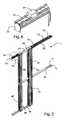
figure 1 shows an exploded view of the modular counter-frame according to the invention; -
figure 2 shows a perspective vied of a counter-frame according tofigure 1 , fully assembled; -
figure 3 shows a front view of a counterframe according tofigure 2 ; -
figure 4 shows a particular of a base cross-beam of counter-frame according to the invention; -
figure 5 shows a particular of an upper cross-beam of counter-frame according to the invention; -
figure 6 shows a portion of a sliding guide of the counter-frame according to the invention; -
figure 7 shows a particular of a fixing bridge of the counter-frame according to the invention; -
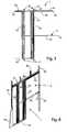
figure 8 shows a counter-frame according to the invention installed within the space of a wall; -
figure 9 shows a pair of counter-frames according to the invention for a double-wing door; -
figure 10 shows a double-wing door offigure 9 installed; -
figure 11 shows coupling bars of counter-frames offigure 9 ; -
figure 12 is an exploded view of a further embodiment of a modular counter-frame according to the invention; -
figure 13 shows some particulars offigure 12 ; -
figure 14 shows a perspective view of counter-frame offigure 12 mounted; and -
figure 15 shows particulars offigure 14 . - Similar parts will be indicated in the various figures by the same reference numbers.
- Making reference to
figures 1-3 , it is possible observing amodular counter-frame 1 for a disappearing sliding door (wing is not shown in the figures) to be installed within a space obtained in a wall (not shown in the figure. In case of plasterboard walls, the space can be realised by a first horizontal guide on the floor, possibly a second horizontal guide fixed to the ceiling, and a plurality of vertical uprights, the ends of which are inserted in, and coupled to, said first and second guides. Plasterboard panels are fixed to said guides and to the uprights by self-threading screws, before the finishing. -
Modular counter-frame 1 mainly comprises abase crossbeam 20, anupper crossbeam 30, two pairs ofuprights 40 and asliding guide 50. Structure ofcounter-frame 1 will be described in the following, also following the main mounting steps. -
Base crossbeam 20 has a "U" shaped cross section, and it can be placed on the floor, whileupper crossbeam 30 has an inverted "U" cross section, and it is substantially parallel with respect to thebase crossbeam 20. Concavity of saidbase crossbeam 20 and of saidupper crossbeam 30 are faced each other. Each one of saiduprights 40 is coupled at the ends ofbase crossbeam 20 and to theupper crossbeam 30. -
Uprights 40 are secrion bars, preferably realised by forming. They can couple withlateral walls base crossbeam 20 and of saidupper crossbeam 30, by snap-fit with suitable coupling elements, respectively indicated byreference numbers -
Figures 4 and5 show in detail saidcoupling elements base crossbeam 20 and of saidupper crossbeam 30, which, in the present embodiment are the same; therefore, only the coupling element of saidbase crossbeam 20 will be described in detail. Particularly, saidcoupling element 22 comprises a pair of folded tabs, projecting outward with respect to saidlateral walls 21, that can be inserted into correspondingvertical grooves 43 of said uprights, so as to prevent that the latter can move from the wished position. Saidcoupling element 22 also comprises a pair ofinsertion tongues 24 with a funnel shape, coupling with seats realised in re-entering parts aside theupright 40, and an insertion and blockingtongue 25, also comprising an elastically preloaded notching 26, suitable to enter in acorresponding slot 41 realised onupright 40 surface, in the re-entering portion between the twogrooves 43, so as to block upright in position once inserted and coupled with thecoupling element 22. - Once coupled uprights 40, said
base crossbeam 20, saidupper crossbeam 30 and said uprights 40 define aspace 60 that can receive a wing. -
Profili 42 are fixed, by screws, on theuprights 40 defining entrance ofspace 60 for inserting the wing, and namely on their leading edges. - Sliding
guide 50, realised as well by extrusion, defines aninner channel 51, within which carriages (not shown in the figures) can be inserted, to which a wing is coupled, so that the latter can slide to enter/exit fromspace 60. - Sliding
guide 50, made up of a section bar, preferably realised by extrusion, can be sliding inserted in saidupper crossbeam 30. The latter has areference tooth 37, that can interfere with a corresponding notch (not shown in the figures) obtained on said slidingguide 50, so as to determine final position of each one of the parts. - Sliding
guide 50 is also provided withreference notches 52, for adjusting its length according to the width of the wing employed (e.g. for a size standard set of 80 cm, 90 cm and 100 cm), and on the basis of installation ofcounter-frame 1 for a single- or double-wing door. By saidreference notches 52, an operator can properly cut slidingguide 50 by a standard cutting tool (not shown in the figures). Thus, whenreference tooth 37 interferes with said notch, saidspace 60 defined by saidbase crossbeam 20, by saidupper crossbeam 30 and byuprights 40, besides by the opening of wall in which counter-frame 1 is installed, is already conformed to the wing size. - At the sliding end of sliding guide 50 (reference is made also to
figure 6 ), fixingsquare elements 53 are coupled by screws or like, also suitable to permit fixing ofcounter-frame 1 with said front opening. Further,square element 53 coupling with the eventually cut end for adapting the sliding guide to the wing size, also permits compensating possible imprecision due to the same cutting. - One or more fixing bridge 54 (see also
figure 7 ) are sliding coupled, and then fixed, to said slidingguide 50, and are also suitable to fixing ofcounter-frame 1 to the opening edge wherein installingcounter-frame 1. - Finally, once inserted the sliding
guide 50 inupper crossbeam 50, plastic thicknesses 5 that can be suitably cut, are coupled to each side of said slidingguide 50. Said thicknesses 55 substantially make width of slidingguide 50 portion not inserted withinupper crossbeam 30 equal to the whole width of wall. - As it can be noted from figures,
base crossbeam 20 is larger thanupper crossbeam 30. As it will be clearer in the following, this is useful for an alternative mounting ofcounter-frame 1. In any case, saidbase crossbeam 20 can, with respect to the upper crossbeam 30: - have the same length;
- be longer, being it necessary adapting its length by cutting the possible exceeding part, to the dimension of the specific wing;
- be longer and partially juxtaposed to the horizontal guide on the floor of the plasterboard wall. This opportunity also permits a higher precision when realising the whole plasterboard wall within which the door is inserted.
- Before installing the
counter-frame 1, it is also provided arod 70. Length of the latter is adjusted on the basis of the wing width byreference notches 71, by which operator cuts the possible exceeding part. A fixing square element is preferably coupled to theend 72 of saidrod 70. Then, saidrod 70 is inserted, as shown in the figure, withinspace 60 and fixed to section bars 42 by two holes realised on the same. - Then, it is possible installing
counter-frame 1. Particularly, making reference tofigure 8 , operator realising plasterboard wall makes opening A perimeter for counter-frame byhorizontal guides 81 and uprights 82 (to whichpanel 83 will be coupled). Then, counter-frame 1 is placed within opening A, fixing it by fixingsquare elements 53, bridges 54 and possible square element fixed torod 70. Saidrod 70 keeps fixed distance betweenuprights 40 in a point which is substantially at half of their length. Thus, when plasterboards panels are fixed touprights 40 by self-threading screws, their flexion is prevented. After fixing of plasterboards panels touprights 40,rod 70 is removed. -
Figures 12 - 15 show a further embodiment ofmodular counter-frame 1 according to the invention, providing only theupper crossbeam 30, the uprights of which couple by snap-fit coupling described in the above, while at the bottom it is provided an "U" shaped base crossbeam 20', provided with threadedpins 27, to which said uprights can be fixed by nuts 27'. - In the present embodiment,
uprights 40 have laterally, and in their lower portion, a plurality ofnotches 45 at different heights, for adjusting cutting, and a plurality ofholes groups 44, eachhole group 44 being placed at different heights, in correspondence of eachnotch 45. Said threadedpins 27 of said base crossbeam 20' is can enter within each one of said hole groups 44. - By said embodiment, it is possible adjusting length of said uprights 40. Particularly, it is sufficient cutting said uprights 40 along said
notches 45, in order to select the (same) measure of all theuprights 40, fixing each upright 40 to the threaded pins 27 of the "U" shaped base crossbeam 20', inserting said threadedpins 27 withinholes 44 of thecorresponding upright 40 and screwing nuts 27' on said threaded pins 27. - Thus, it is possible easily adjusting height of
modular counterframe 1. - As it can be noted,
counterframe 1 according to the invention can be mounted to be then inserted within opening A of a wall. However, it is also possible assemblingcounterframe 1 and the inserting the same within the wall while the same is realised. For example, while installer places horizontal guide on the floor, it is possible juxtaposing the latter to thebase crossbeam 20, coupling them, thus limiting the risk of misalignment of the wall. Only then it will be placed and fixed the upper horizontal guide tocounterframe 1, to define opening A. In other words, it is first assembledcounterframe 1, and then the wall. - Making reference to
figures 9 - 11 , it is observed thatcounterframe 1 according to the invention is also prepared for installation of double wing doors, so that twocounterframes 1 are provided opposed each other, and coupled at the ends of the relevant slidingguides 50 bybars 56 that can be fixed by suitable screws without passage interruption of the sliding guides. - The present invention has been described for illustrative, but not limitative purposes, according to its preferred embodiments, but it is to be understood that variations and/or modification can be introduced by those skilled in the art without departing from the relevant scope, as defined in the enclosed claims.
Claims (15)
- Modular counter-frame (1) for disappearing sliding doors, of the type that can be installed in an opening (A) of a wall, comprising
a base crossbeam (20),
an upper crossbeam (30) arranged parallel with respect to said base crossbeam (20: 20'),
two or more pairs of uprights (40), to which wall panels (83) are fixable by fixing means, such as screws and like, each upright (40) of each pair being faced and spaced with respect the upright (40) of the same pair and coupled with said base crossbeam (20) and with said upper crossbeam (30), the assembly of said pairs of uprights (40), said base crossbeam (20) and said upper crossbeam (30) defining a sliding cavity (60) for a wing, and
a linear sliding guide (50) inserted within said upper crossbeam (30) in such way that the ends of said sliding guide (50) extend out from it, wherein sliding means, such as carriages, are moving couplable with said wing,
characterized in that
said base crossbeam (20) and said upper crossbeam (30) have respectively a "U" shaped and an inverted "U" shaped cross section and comprise (21, 31) coupling elements (22, 32) on the lateral walls of said two or more pairs of uprights (40),
and in that said uprights (40) are couplable by snap-fit coupling with said coupling means (22, 32) of said upper crossbeam. - Counter-frame (1) according to claim 1, characterized in that each one of said uprights (40) is realized by two or more vertical grooves (43) and provides on each end at least one slot (41), that is made in the re-entering portion between the said grooves (43),
and in that each coupling element (22, 32) of said upper crossbeam comprises two or more folded tabs (23, 33), arranged projected outwardly with respect to said lateral walls (21, 31) and each one capable of inserting in one corresponding groove (43),
one or more insertion tongues (24, 34) with a funnel-shaped end coupling with seats arranged in the re-entering portions at the sides of the respective upright (40) and at least one insertion and blocking tongue (25, 35) comprising an elastically preloaded notching (26, 36), said insertion and blocking tongue (25, 35) coupling with the re-entering portion between said grooves (43) and said elastically preloaded notching (26, 36) coupling with said slot (41). - Counter-frame (1) according to anyone of the preceding claims, characterized in that said uprights (40) is snap-fit coupled with said coupling elements (22) of said base crossbeam (20).
- Counter-frame (1) according to claim 3, characterized in that each one of said uprights (40 have, on each one of its ends, at least a slot (41), obtained in the re-entering portion between said grooves (43),
and in that each coupling element (22) of said base crossbeam (40) comprises
two or more folded tabs (23), arranged projected outwardly with respect to said lateral walls (21) and each one capable of inserting in one corresponding groove (43),
one or more insertion tongues (24) with a funnel-shaped end, coupling with seats arranged in the re-entering portions at the sides of the respective upright (40) and at least one insertion and blocking tongue (25) comprising an elastically preloaded notching (26), said insertion and blocking tongue (25) coupling with the re-entering portion between said grooves (43) and said elastically preloaded notching (26) coupling with said slot (41). - Counter-frame (1) according to claim 1 or 2, characterized in that
said base crossbeam (20') can be provided with threaded pins (27), to which said uprights (40) can be fixed by nuts (27'), and
each one of said uprights (40) have a plurality of notchings (25) along its lower portion, along which said uprights (40) can be cut to adjust their length, said notchings (45) being provided at different heights, and a plurality of hole groups (44), each hole groups (44) being placed at different heights in correspondence of each notching (45), said threaded pins (27) being able to be inserted within said holes (44) of said base crossbeam (20'), to which they can be fixed by nuts (27'). - Counter-frame (1) according to anyone of the preceding claims, characterized in that it comprises means (53, 54) for coupling with said wall, said coupling means (53, 54) comprising one or more fixation bridges (54), slidably inserted on said sliding guide (50)and fixed to the same by fixation means, such as screws and like, and at least one fixation square (53) fixed to an end of said sliding guide (50) by fixation means, such as screws and like.
- Counter-frame (1) according to anyone of the preceding claims, characterized in that said upper crossbeam (30) comprises a reference tooth (37), and said sliding guide (50) is provided with:- reference marks (52) on the surface, for adjusting its length according to the measurement of the width of the wing to be installed within said counter-frame (1) and/or according to the installation of said counter-frame (1) for a single or double wing door; and- a notch with which said reference tooth (37) interferes, so as to set the reciprocal final assembly position of said sliding guide (50) with said upper crossbeam (30).
- Counter-frame (1) according to anyone of the preceding claims, characterized in that it comprises thickness elements (55) made of plastic material coupled with each side of said sliding guide (50), arranged so that the width of the portion of the sliding guide (50) non inserted in said upper crossbeam (30) is substantially equal to the overall width of said wall.
- Counter-frame (1) according to anyone of the preceding claims, characterized in that said base crossbeam (20) is selected among one of the following groups:- said base crossbeam (20) has a length substantially equal to the length of said upper crossbeam (30);- said base crossbeam (20) has a length greater than the length of said upper crossbeam (30), said length being eventually adjustable by cutting on the basis of the width of the wing to be installed within said counter-frame (1).
- Counter-frame (1) according to anyone of the preceding claims, characterized in that it is couplable with a further counter-frame (1) arranged opposed for realizing double wing doors, the ends of the respective sliding guides (50) of said counterframes (1) being fixed each other by coupling means, such as bars (56).
- Kit of a modular counter-frame (1) as defined in preceding claims, characterized in that it comprises:- at least one base crossbeam (20; 20');- at least one upper crossbeam (30);- two or more pairs of uprights (40);- at least one sliding guide (50); and- coupling means (53, 54) such as one or more fixation bridges (54) and one or more fixation squares (53).
- Kit according to claim 11, characterized in that it comprises at least one rod (70), provided with reference marks (71).
- Method for assembling a disappearing sliding door comprising a counter-frame (1) as defined in claims 1-10, characterized in that it comprises the following steps:- arranging said base crossbeam (20) and said upper crossbeam (30);- coupling said uprights (40) with said base crossbeam (20) and with said upper crossbeam (30) by snap-fit coupling;- cutting said sliding guide (50) and inserting the same within said upper crossbeam (30);- providing a rod (70) provided with reference marks (71) adjusting its length by cutting, eventually coupling a square to an end of said rod (70), inserting said rod (70) between said uprights in said cavity (60) and fixing said rod (70) to said uprights (40) preferably to the profiles (42) fixed to the pair of uprights (40) which define the entrance of said cavity (60);- fixing said counter-frame to said wall by said coupling means (53, 54);- fixing the wall panels, preferably plasterboard panels, to said uprights (40) by fixing member, like screws and like;- removing said rod (70); and- coupling a wing with said sliding means of said sliding guide (50).
- Method according to claim 13, wherein said wall comprises horizontal guides and vertical rods for fixing to them further wall panels, preferably plasterboard panels, characterized in that it comprises the following further step:- arranging said base crossbeam (20) so as to superimpose on the same at least partially said horizontal guide of said wall arranged on the floor.
- Method according to anyone of claims 13 or 14, characterized in that it comprises the following further step:- cutting the eventual exceeding length of said base crossbeam (20) according to the dimension of the employed wing.
Applications Claiming Priority (1)
| Application Number | Priority Date | Filing Date | Title |
|---|---|---|---|
| ITRM2009A000458A IT1395877B1 (en) | 2009-09-11 | 2009-09-11 | MODULAR COUNTERFRAME FOR RETRACTABLE SLIDING DOORS AND RELATED KIT AND MOUNTING METHOD. |
Publications (2)
| Publication Number | Publication Date |
|---|---|
| EP2299043A1 true EP2299043A1 (en) | 2011-03-23 |
| EP2299043B1 EP2299043B1 (en) | 2012-12-12 |
Family
ID=41831390
Family Applications (1)
| Application Number | Title | Priority Date | Filing Date |
|---|---|---|---|
| EP20100425238 Active EP2299043B1 (en) | 2009-09-11 | 2010-07-16 | Modular counter-frame for disappearing sliding doors and relevant kit and assembling method |
Country Status (3)
| Country | Link |
|---|---|
| EP (1) | EP2299043B1 (en) |
| ES (1) | ES2398049T3 (en) |
| IT (1) | IT1395877B1 (en) |
Cited By (11)
| Publication number | Priority date | Publication date | Assignee | Title |
|---|---|---|---|---|
| CN102926626A (en) * | 2012-11-21 | 2013-02-13 | 陈良明 | Sliding door without lower rail |
| EP2660417A1 (en) | 2012-04-30 | 2013-11-06 | Kriket Armazones S.L. | Subframe for sliding doors |
| EP2886775A1 (en) * | 2013-12-23 | 2015-06-24 | Eclisse Srl | Rear post for in-wall frames of retractable sliding doors |
| WO2015181530A1 (en) * | 2014-05-28 | 2015-12-03 | Linear Building Innovations Limited | Support frame for sliding door systems |
| WO2015189683A1 (en) * | 2014-06-13 | 2015-12-17 | Koblenz S.P.A. | Easily transported and assembled wall structure with or for sliding door |
| WO2015189681A1 (en) * | 2014-06-13 | 2015-12-17 | Koblenz S.P.A. | Improved wall structure with of for sliding door or slide-swinging door |
| GB2560144A (en) * | 2016-11-17 | 2018-09-05 | Home Decor Gb Ltd | Modular track system |
| IT201800004059A1 (en) * | 2018-03-29 | 2019-09-29 | Eclisse Srl | METHOD FOR OBTAINING A VERTICAL OR HORIZONTAL PROFILE FOR THE INTERCONNECTION TO PLASTERBOARD WALLS |
| IT201800004060A1 (en) * | 2018-03-29 | 2019-09-29 | Eclisse Srl | METHOD FOR OBTAINING A VERTICAL OR HORIZONTAL PROFILE FOR THE INTERCONNECTION TO PLASTERBOARD WALLS AND THE RELATIVE METHOD FOR OBTAINING IT |
| IT201900015057A1 (en) * | 2019-08-27 | 2021-02-27 | Eclisse Srl | ALIGNMENT DEVICE FOR LAYING COUNTERFRAMES FOR SLIDING DOORS. |
| IT201900021072A1 (en) * | 2019-11-13 | 2021-05-13 | Protek S R L | Highly versatile structure for sliding architectural elements. |
Families Citing this family (1)
| Publication number | Priority date | Publication date | Assignee | Title |
|---|---|---|---|---|
| CN203308298U (en) * | 2013-05-13 | 2013-11-27 | 佛山市理想卫浴有限公司 | Door assembly |
Citations (2)
| Publication number | Priority date | Publication date | Assignee | Title |
|---|---|---|---|---|
| EP0751275A2 (en) * | 1995-06-28 | 1997-01-02 | KRONA I S.p.A. | Easily transported and assembled wall structure with sliding door |
| EP2072744A2 (en) * | 2007-12-19 | 2009-06-24 | Veka AG | Architrave profile for a lifting sliding door |
-
2009
- 2009-09-11 IT ITRM2009A000458A patent/IT1395877B1/en active
-
2010
- 2010-07-16 ES ES10425238T patent/ES2398049T3/en active Active
- 2010-07-16 EP EP20100425238 patent/EP2299043B1/en active Active
Patent Citations (3)
| Publication number | Priority date | Publication date | Assignee | Title |
|---|---|---|---|---|
| EP0751275A2 (en) * | 1995-06-28 | 1997-01-02 | KRONA I S.p.A. | Easily transported and assembled wall structure with sliding door |
| IT1277197B1 (en) | 1995-06-28 | 1997-11-05 | Krona I S P A | WALL STRUCTURE WITH SLIDING DOOR FOR EASY TRANSPORT AND ASSEMBLY |
| EP2072744A2 (en) * | 2007-12-19 | 2009-06-24 | Veka AG | Architrave profile for a lifting sliding door |
Cited By (21)
| Publication number | Priority date | Publication date | Assignee | Title |
|---|---|---|---|---|
| EP2660417A1 (en) | 2012-04-30 | 2013-11-06 | Kriket Armazones S.L. | Subframe for sliding doors |
| CN102926626A (en) * | 2012-11-21 | 2013-02-13 | 陈良明 | Sliding door without lower rail |
| EP2886775A1 (en) * | 2013-12-23 | 2015-06-24 | Eclisse Srl | Rear post for in-wall frames of retractable sliding doors |
| WO2015181530A1 (en) * | 2014-05-28 | 2015-12-03 | Linear Building Innovations Limited | Support frame for sliding door systems |
| WO2015189683A1 (en) * | 2014-06-13 | 2015-12-17 | Koblenz S.P.A. | Easily transported and assembled wall structure with or for sliding door |
| WO2015189681A1 (en) * | 2014-06-13 | 2015-12-17 | Koblenz S.P.A. | Improved wall structure with of for sliding door or slide-swinging door |
| RU2677965C2 (en) * | 2014-06-13 | 2019-01-22 | Кобленц С.п.А. | Improved wall structure with sliding door or slide-swinging door |
| RU2682342C2 (en) * | 2014-06-13 | 2019-03-19 | Кобленц С.п.А. | Easily transported and assembled wall structure with or for sliding door |
| GB2560144A (en) * | 2016-11-17 | 2018-09-05 | Home Decor Gb Ltd | Modular track system |
| GB2560144B (en) * | 2016-11-17 | 2021-10-27 | Home Decor Gb Ltd | Modular track system |
| IT201800004060A1 (en) * | 2018-03-29 | 2019-09-29 | Eclisse Srl | METHOD FOR OBTAINING A VERTICAL OR HORIZONTAL PROFILE FOR THE INTERCONNECTION TO PLASTERBOARD WALLS AND THE RELATIVE METHOD FOR OBTAINING IT |
| WO2019185177A1 (en) * | 2018-03-29 | 2019-10-03 | Eclisse S.R.L. | Method for obtaining a vertical or horizontal profile for interconnection to plasterboard walls |
| WO2019185176A1 (en) * | 2018-03-29 | 2019-10-03 | Eclisse S.R.L. | Method for obtaining a vertical or horizontal profiled element for the interconnection of plasterboard panels to walls and element obtained with such method |
| IT201800004059A1 (en) * | 2018-03-29 | 2019-09-29 | Eclisse Srl | METHOD FOR OBTAINING A VERTICAL OR HORIZONTAL PROFILE FOR THE INTERCONNECTION TO PLASTERBOARD WALLS |
| RU2768299C1 (en) * | 2018-03-29 | 2022-03-23 | Эклиссе С.Р.Л. | Method of producing a vertical or horizontal shaped element for interconnecting gypsum panels to walls and an element obtained using this method |
| US11499309B2 (en) | 2018-03-29 | 2022-11-15 | Eclisse S.R.L. | Method for obtaining a vertical or horizontal profiled element for the interconnection of plasterboard panels to walls and element obtained with such method |
| US11761202B2 (en) | 2018-03-29 | 2023-09-19 | Eclisse S.R.L. | Method for obtaining a vertical or horizontal profiled element for the interconnection of plasterboard panels to walls and element obtained with such method |
| IT201900015057A1 (en) * | 2019-08-27 | 2021-02-27 | Eclisse Srl | ALIGNMENT DEVICE FOR LAYING COUNTERFRAMES FOR SLIDING DOORS. |
| EP3789576A1 (en) * | 2019-08-27 | 2021-03-10 | Eclisse S.R.L. | Alignment device for installing in-wall frames for sliding doors |
| IT201900021072A1 (en) * | 2019-11-13 | 2021-05-13 | Protek S R L | Highly versatile structure for sliding architectural elements. |
| EP3822448A1 (en) * | 2019-11-13 | 2021-05-19 | Protek S.r.l. | Structure for highly versatile sliding architectural elements |
Also Published As
| Publication number | Publication date |
|---|---|
| IT1395877B1 (en) | 2012-10-26 |
| ES2398049T3 (en) | 2013-03-13 |
| EP2299043B1 (en) | 2012-12-12 |
| ITRM20090458A1 (en) | 2011-03-12 |
Similar Documents
| Publication | Publication Date | Title |
|---|---|---|
| EP2299043B1 (en) | Modular counter-frame for disappearing sliding doors and relevant kit and assembling method | |
| US10422140B2 (en) | Screen enclosure support assembly | |
| DK2479371T3 (en) | Profile bar, which locks into a panel and panel system. | |
| US7418805B2 (en) | Modular framing system and a method of construction thereof | |
| EP2348187B1 (en) | Roller blind box | |
| CA2788878A1 (en) | Fastener-less track assembly for supporting wall studs | |
| EP0570374B1 (en) | Framework of partition walls | |
| US11859444B1 (en) | Header assembly and method for installing retractable screens | |
| EP2602416A1 (en) | Interconnection device for retractable sliding doors | |
| DE602005001052T2 (en) | In the concrete floor to be integrated partition | |
| EP3676465A1 (en) | System for mounting wall cladding panels | |
| DE102011001726B4 (en) | Module for receiving a sliding door, sliding door device and method for mounting a sliding door device | |
| KR101499589B1 (en) | Frame structure for frame door | |
| EP1916750A2 (en) | Method for fixing electrical boxes to walls and support for implementing the method | |
| EP0652350A1 (en) | Support and constraint device for a roller shutter box assembly with shutter | |
| EP1211770B1 (en) | Transom profile | |
| DE102017120254A1 (en) | Angle element and reveal panel with an angle element | |
| ITPN20110011A1 (en) | AUTOPORTANT BUILDING MODULE SUITABLE FOR CONSTRUCTION OF REINFORCED CONCRETE FLOORS. | |
| US9464474B2 (en) | Door buck | |
| EP2369118B1 (en) | Roller shutter housing and insulation section for a roller shutter housing | |
| DE3923621A1 (en) | PROFILE FOR SUPPORTING CEILING PANELS | |
| AT414138B (en) | STRUCTURE FOR CONSTRUCTION OF WALLS | |
| EP0723054B1 (en) | Built-in frame, particularly for inspection holes in a building wall | |
| DE102010064687B3 (en) | Method of manufacturing a roller shutter box | |
| DE102013110649B4 (en) | System for arranging and wiring electrical units |
Legal Events
| Date | Code | Title | Description |
|---|---|---|---|
| PUAI | Public reference made under article 153(3) epc to a published international application that has entered the european phase |
Free format text: ORIGINAL CODE: 0009012 |
|
| AK | Designated contracting states |
Kind code of ref document: A1 Designated state(s): AL AT BE BG CH CY CZ DE DK EE ES FI FR GB GR HR HU IE IS IT LI LT LU LV MC MK MT NL NO PL PT RO SE SI SK SM TR |
|
| AX | Request for extension of the european patent |
Extension state: BA ME RS |
|
| 17P | Request for examination filed |
Effective date: 20110920 |
|
| GRAP | Despatch of communication of intention to grant a patent |
Free format text: ORIGINAL CODE: EPIDOSNIGR1 |
|
| RIC1 | Information provided on ipc code assigned before grant |
Ipc: E06B 3/988 20060101ALI20120718BHEP Ipc: E06B 3/46 20060101AFI20120718BHEP Ipc: E04B 2/78 20060101ALI20120718BHEP Ipc: E04B 2/76 20060101ALI20120718BHEP |
|
| GRAS | Grant fee paid |
Free format text: ORIGINAL CODE: EPIDOSNIGR3 |
|
| GRAA | (expected) grant |
Free format text: ORIGINAL CODE: 0009210 |
|
| RAP1 | Party data changed (applicant data changed or rights of an application transferred) |
Owner name: SCRIGNO HOLDING S.P.A. |
|
| AK | Designated contracting states |
Kind code of ref document: B1 Designated state(s): AL AT BE BG CH CY CZ DE DK EE ES FI FR GB GR HR HU IE IS IT LI LT LU LV MC MK MT NL NO PL PT RO SE SI SK SM TR |
|
| REG | Reference to a national code |
Ref country code: GB Ref legal event code: FG4D |
|
| REG | Reference to a national code |
Ref country code: CH Ref legal event code: EP |
|
| REG | Reference to a national code |
Ref country code: AT Ref legal event code: REF Ref document number: 588422 Country of ref document: AT Kind code of ref document: T Effective date: 20121215 |
|
| REG | Reference to a national code |
Ref country code: IE Ref legal event code: FG4D |
|
| REG | Reference to a national code |
Ref country code: DE Ref legal event code: R096 Ref document number: 602010004090 Country of ref document: DE Effective date: 20130207 |
|
| REG | Reference to a national code |
Ref country code: ES Ref legal event code: FG2A Ref document number: 2398049 Country of ref document: ES Kind code of ref document: T3 Effective date: 20130313 |
|
| PG25 | Lapsed in a contracting state [announced via postgrant information from national office to epo] |
Ref country code: SE Free format text: LAPSE BECAUSE OF FAILURE TO SUBMIT A TRANSLATION OF THE DESCRIPTION OR TO PAY THE FEE WITHIN THE PRESCRIBED TIME-LIMIT Effective date: 20121212 Ref country code: HR Free format text: LAPSE BECAUSE OF FAILURE TO SUBMIT A TRANSLATION OF THE DESCRIPTION OR TO PAY THE FEE WITHIN THE PRESCRIBED TIME-LIMIT Effective date: 20121212 Ref country code: LT Free format text: LAPSE BECAUSE OF FAILURE TO SUBMIT A TRANSLATION OF THE DESCRIPTION OR TO PAY THE FEE WITHIN THE PRESCRIBED TIME-LIMIT Effective date: 20121212 Ref country code: FI Free format text: LAPSE BECAUSE OF FAILURE TO SUBMIT A TRANSLATION OF THE DESCRIPTION OR TO PAY THE FEE WITHIN THE PRESCRIBED TIME-LIMIT Effective date: 20121212 Ref country code: NO Free format text: LAPSE BECAUSE OF FAILURE TO SUBMIT A TRANSLATION OF THE DESCRIPTION OR TO PAY THE FEE WITHIN THE PRESCRIBED TIME-LIMIT Effective date: 20130312 |
|
| REG | Reference to a national code |
Ref country code: NL Ref legal event code: VDEP Effective date: 20121212 |
|
| REG | Reference to a national code |
Ref country code: AT Ref legal event code: MK05 Ref document number: 588422 Country of ref document: AT Kind code of ref document: T Effective date: 20121212 |
|
| REG | Reference to a national code |
Ref country code: LT Ref legal event code: MG4D |
|
| PG25 | Lapsed in a contracting state [announced via postgrant information from national office to epo] |
Ref country code: LV Free format text: LAPSE BECAUSE OF FAILURE TO SUBMIT A TRANSLATION OF THE DESCRIPTION OR TO PAY THE FEE WITHIN THE PRESCRIBED TIME-LIMIT Effective date: 20121212 Ref country code: SI Free format text: LAPSE BECAUSE OF FAILURE TO SUBMIT A TRANSLATION OF THE DESCRIPTION OR TO PAY THE FEE WITHIN THE PRESCRIBED TIME-LIMIT Effective date: 20121212 Ref country code: GR Free format text: LAPSE BECAUSE OF FAILURE TO SUBMIT A TRANSLATION OF THE DESCRIPTION OR TO PAY THE FEE WITHIN THE PRESCRIBED TIME-LIMIT Effective date: 20130313 |
|
| PG25 | Lapsed in a contracting state [announced via postgrant information from national office to epo] |
Ref country code: IS Free format text: LAPSE BECAUSE OF FAILURE TO SUBMIT A TRANSLATION OF THE DESCRIPTION OR TO PAY THE FEE WITHIN THE PRESCRIBED TIME-LIMIT Effective date: 20130412 Ref country code: BE Free format text: LAPSE BECAUSE OF FAILURE TO SUBMIT A TRANSLATION OF THE DESCRIPTION OR TO PAY THE FEE WITHIN THE PRESCRIBED TIME-LIMIT Effective date: 20121212 Ref country code: EE Free format text: LAPSE BECAUSE OF FAILURE TO SUBMIT A TRANSLATION OF THE DESCRIPTION OR TO PAY THE FEE WITHIN THE PRESCRIBED TIME-LIMIT Effective date: 20121212 Ref country code: AT Free format text: LAPSE BECAUSE OF FAILURE TO SUBMIT A TRANSLATION OF THE DESCRIPTION OR TO PAY THE FEE WITHIN THE PRESCRIBED TIME-LIMIT Effective date: 20121212 Ref country code: SK Free format text: LAPSE BECAUSE OF FAILURE TO SUBMIT A TRANSLATION OF THE DESCRIPTION OR TO PAY THE FEE WITHIN THE PRESCRIBED TIME-LIMIT Effective date: 20121212 Ref country code: CZ Free format text: LAPSE BECAUSE OF FAILURE TO SUBMIT A TRANSLATION OF THE DESCRIPTION OR TO PAY THE FEE WITHIN THE PRESCRIBED TIME-LIMIT Effective date: 20121212 Ref country code: BG Free format text: LAPSE BECAUSE OF FAILURE TO SUBMIT A TRANSLATION OF THE DESCRIPTION OR TO PAY THE FEE WITHIN THE PRESCRIBED TIME-LIMIT Effective date: 20130312 |
|
| PG25 | Lapsed in a contracting state [announced via postgrant information from national office to epo] |
Ref country code: RO Free format text: LAPSE BECAUSE OF FAILURE TO SUBMIT A TRANSLATION OF THE DESCRIPTION OR TO PAY THE FEE WITHIN THE PRESCRIBED TIME-LIMIT Effective date: 20121212 Ref country code: NL Free format text: LAPSE BECAUSE OF FAILURE TO SUBMIT A TRANSLATION OF THE DESCRIPTION OR TO PAY THE FEE WITHIN THE PRESCRIBED TIME-LIMIT Effective date: 20121212 Ref country code: PT Free format text: LAPSE BECAUSE OF FAILURE TO SUBMIT A TRANSLATION OF THE DESCRIPTION OR TO PAY THE FEE WITHIN THE PRESCRIBED TIME-LIMIT Effective date: 20130412 Ref country code: PL Free format text: LAPSE BECAUSE OF FAILURE TO SUBMIT A TRANSLATION OF THE DESCRIPTION OR TO PAY THE FEE WITHIN THE PRESCRIBED TIME-LIMIT Effective date: 20121212 |
|
| PLBE | No opposition filed within time limit |
Free format text: ORIGINAL CODE: 0009261 |
|
| STAA | Information on the status of an ep patent application or granted ep patent |
Free format text: STATUS: NO OPPOSITION FILED WITHIN TIME LIMIT |
|
| PG25 | Lapsed in a contracting state [announced via postgrant information from national office to epo] |
Ref country code: DK Free format text: LAPSE BECAUSE OF FAILURE TO SUBMIT A TRANSLATION OF THE DESCRIPTION OR TO PAY THE FEE WITHIN THE PRESCRIBED TIME-LIMIT Effective date: 20121212 |
|
| 26N | No opposition filed |
Effective date: 20130913 |
|
| PG25 | Lapsed in a contracting state [announced via postgrant information from national office to epo] |
Ref country code: CY Free format text: LAPSE BECAUSE OF FAILURE TO SUBMIT A TRANSLATION OF THE DESCRIPTION OR TO PAY THE FEE WITHIN THE PRESCRIBED TIME-LIMIT Effective date: 20121212 |
|
| REG | Reference to a national code |
Ref country code: DE Ref legal event code: R097 Ref document number: 602010004090 Country of ref document: DE Effective date: 20130913 |
|
| REG | Reference to a national code |
Ref country code: IE Ref legal event code: MM4A |
|
| PG25 | Lapsed in a contracting state [announced via postgrant information from national office to epo] |
Ref country code: DE Free format text: LAPSE BECAUSE OF NON-PAYMENT OF DUE FEES Effective date: 20140201 |
|
| REG | Reference to a national code |
Ref country code: DE Ref legal event code: R119 Ref document number: 602010004090 Country of ref document: DE Effective date: 20140201 |
|
| PG25 | Lapsed in a contracting state [announced via postgrant information from national office to epo] |
Ref country code: IE Free format text: LAPSE BECAUSE OF NON-PAYMENT OF DUE FEES Effective date: 20130716 |
|
| REG | Reference to a national code |
Ref country code: CH Ref legal event code: PL |
|
| GBPC | Gb: european patent ceased through non-payment of renewal fee |
Effective date: 20140716 |
|
| PG25 | Lapsed in a contracting state [announced via postgrant information from national office to epo] |
Ref country code: CH Free format text: LAPSE BECAUSE OF NON-PAYMENT OF DUE FEES Effective date: 20140731 Ref country code: LI Free format text: LAPSE BECAUSE OF NON-PAYMENT OF DUE FEES Effective date: 20140731 |
|
| PG25 | Lapsed in a contracting state [announced via postgrant information from national office to epo] |
Ref country code: SM Free format text: LAPSE BECAUSE OF FAILURE TO SUBMIT A TRANSLATION OF THE DESCRIPTION OR TO PAY THE FEE WITHIN THE PRESCRIBED TIME-LIMIT Effective date: 20121212 Ref country code: GB Free format text: LAPSE BECAUSE OF NON-PAYMENT OF DUE FEES Effective date: 20140716 |
|
| PG25 | Lapsed in a contracting state [announced via postgrant information from national office to epo] |
Ref country code: MT Free format text: LAPSE BECAUSE OF FAILURE TO SUBMIT A TRANSLATION OF THE DESCRIPTION OR TO PAY THE FEE WITHIN THE PRESCRIBED TIME-LIMIT Effective date: 20121212 Ref country code: TR Free format text: LAPSE BECAUSE OF FAILURE TO SUBMIT A TRANSLATION OF THE DESCRIPTION OR TO PAY THE FEE WITHIN THE PRESCRIBED TIME-LIMIT Effective date: 20121212 |
|
| PG25 | Lapsed in a contracting state [announced via postgrant information from national office to epo] |
Ref country code: MK Free format text: LAPSE BECAUSE OF FAILURE TO SUBMIT A TRANSLATION OF THE DESCRIPTION OR TO PAY THE FEE WITHIN THE PRESCRIBED TIME-LIMIT Effective date: 20121212 Ref country code: LU Free format text: LAPSE BECAUSE OF NON-PAYMENT OF DUE FEES Effective date: 20130716 Ref country code: MC Free format text: LAPSE BECAUSE OF FAILURE TO SUBMIT A TRANSLATION OF THE DESCRIPTION OR TO PAY THE FEE WITHIN THE PRESCRIBED TIME-LIMIT Effective date: 20121212 Ref country code: HU Free format text: LAPSE BECAUSE OF FAILURE TO SUBMIT A TRANSLATION OF THE DESCRIPTION OR TO PAY THE FEE WITHIN THE PRESCRIBED TIME-LIMIT; INVALID AB INITIO Effective date: 20100716 |
|
| REG | Reference to a national code |
Ref country code: FR Ref legal event code: PLFP Year of fee payment: 7 |
|
| REG | Reference to a national code |
Ref country code: FR Ref legal event code: PLFP Year of fee payment: 8 |
|
| REG | Reference to a national code |
Ref country code: FR Ref legal event code: PLFP Year of fee payment: 9 |
|
| PG25 | Lapsed in a contracting state [announced via postgrant information from national office to epo] |
Ref country code: AL Free format text: LAPSE BECAUSE OF FAILURE TO SUBMIT A TRANSLATION OF THE DESCRIPTION OR TO PAY THE FEE WITHIN THE PRESCRIBED TIME-LIMIT Effective date: 20121212 |
|
| PGFP | Annual fee paid to national office [announced via postgrant information from national office to epo] |
Ref country code: IT Payment date: 20200703 Year of fee payment: 11 |
|
| PG25 | Lapsed in a contracting state [announced via postgrant information from national office to epo] |
Ref country code: IT Free format text: LAPSE BECAUSE OF NON-PAYMENT OF DUE FEES Effective date: 20210716 |
|
| PGFP | Annual fee paid to national office [announced via postgrant information from national office to epo] |
Ref country code: FR Payment date: 20220622 Year of fee payment: 13 |
|
| PGFP | Annual fee paid to national office [announced via postgrant information from national office to epo] |
Ref country code: ES Payment date: 20220802 Year of fee payment: 13 |