EP2298606A1 - Interior cladding part for a vehicle passenger area and production method - Google Patents
Interior cladding part for a vehicle passenger area and production method Download PDFInfo
- Publication number
- EP2298606A1 EP2298606A1 EP09170812A EP09170812A EP2298606A1 EP 2298606 A1 EP2298606 A1 EP 2298606A1 EP 09170812 A EP09170812 A EP 09170812A EP 09170812 A EP09170812 A EP 09170812A EP 2298606 A1 EP2298606 A1 EP 2298606A1
- Authority
- EP
- European Patent Office
- Prior art keywords
- interior trim
- layer
- trim part
- support
- molding
- Prior art date
- Legal status (The legal status is an assumption and is not a legal conclusion. Google has not performed a legal analysis and makes no representation as to the accuracy of the status listed.)
- Granted
Links
- 238000004519 manufacturing process Methods 0.000 title claims abstract description 11
- 238000005253 cladding Methods 0.000 title 1
- 238000000465 moulding Methods 0.000 claims description 27
- 238000002347 injection Methods 0.000 claims description 12
- 239000007924 injection Substances 0.000 claims description 12
- 230000008447 perception Effects 0.000 claims description 10
- 238000001746 injection moulding Methods 0.000 claims description 8
- 235000001674 Agaricus brunnescens Nutrition 0.000 claims description 6
- 239000012815 thermoplastic material Substances 0.000 claims description 6
- 239000013013 elastic material Substances 0.000 claims description 3
- 238000005192 partition Methods 0.000 claims 1
- 238000000034 method Methods 0.000 description 11
- 239000006260 foam Substances 0.000 description 8
- 239000000463 material Substances 0.000 description 8
- 229920001169 thermoplastic Polymers 0.000 description 6
- 239000004416 thermosoftening plastic Substances 0.000 description 6
- 241000233866 Fungi Species 0.000 description 4
- 238000010438 heat treatment Methods 0.000 description 4
- 238000010276 construction Methods 0.000 description 3
- 238000004026 adhesive bonding Methods 0.000 description 2
- 239000006261 foam material Substances 0.000 description 2
- 238000005187 foaming Methods 0.000 description 2
- 238000009417 prefabrication Methods 0.000 description 2
- 239000007787 solid Substances 0.000 description 2
- 238000003466 welding Methods 0.000 description 2
- 230000000295 complement effect Effects 0.000 description 1
- 230000006835 compression Effects 0.000 description 1
- 238000007906 compression Methods 0.000 description 1
- 230000000694 effects Effects 0.000 description 1
- 230000006870 function Effects 0.000 description 1
- 238000003780 insertion Methods 0.000 description 1
- 230000037431 insertion Effects 0.000 description 1
- 239000010985 leather Substances 0.000 description 1
- 239000012778 molding material Substances 0.000 description 1
- 239000005445 natural material Substances 0.000 description 1
- 210000005036 nerve Anatomy 0.000 description 1
- 230000007935 neutral effect Effects 0.000 description 1
- 239000011148 porous material Substances 0.000 description 1
- 238000002360 preparation method Methods 0.000 description 1
- 238000010107 reaction injection moulding Methods 0.000 description 1
- 230000001953 sensory effect Effects 0.000 description 1
- 230000021317 sensory perception Effects 0.000 description 1
- 238000007493 shaping process Methods 0.000 description 1
- 239000004753 textile Substances 0.000 description 1
- 239000002023 wood Substances 0.000 description 1
Images


Classifications
-
- B—PERFORMING OPERATIONS; TRANSPORTING
- B60—VEHICLES IN GENERAL
- B60R—VEHICLES, VEHICLE FITTINGS, OR VEHICLE PARTS, NOT OTHERWISE PROVIDED FOR
- B60R13/00—Elements for body-finishing, identifying, or decorating; Arrangements or adaptations for advertising purposes
- B60R13/02—Internal Trim mouldings ; Internal Ledges; Wall liners for passenger compartments; Roof liners
- B60R13/0237—Side or rear panels
- B60R13/0243—Doors
Definitions
- the invention relates to an interior trim part for a passenger compartment of a vehicle, comprising a molded part which has a front side which forms a decorative wear layer of the interior trim part and at least one carrier layer which forms a rear side of the interior trim part, wherein at least a partial region of the interior trim part having at least one support structure is provided, which creates a pleasant tactile perception on the surface of the sub-area.
- the invention also relates to a method for producing the interior trim part, wherein the interior trim part has a front side with a decorative wear layer and below at least one carrier layer which forms the rear side, and wherein at least a partial area of the interior trim part is provided with a support structure which provides a pleasant tactile perception on the surface of the partial area, comprising the following step: producing a molded part with a decorative wear layer and at least one carrier layer.
- the tactile perception is the sensory perception of mechanical, thermal and pain-sensitive receptors of the nerves.
- the wear layer may, for example, have a surface provided with an aesthetic pattern. Often, scarred leather surfaces, wood grain or other natural material surfaces or textile surfaces are imitated.
- Such an interior trim part is preferably used where a passenger can come into contact with the interior trim part during operation of the vehicle.
- a vehicle door may be provided with an interior trim part having an integrated armrest.
- the interior trim part can also have an ergonomic function, as is the case with an integrated armrest, on which the passenger should be able to rest comfortably.
- the touch gives the passenger a tactile perception of the surface of the interior trim part.
- a support structure is provided under the surface usually, which can absorb the externally applied force.
- the support structure is yielding.
- the flexibility is also felt by the passenger.
- the subsurface structure gives the passenger a sense of the quality of the interior trim part.
- the portion of the interior trim part in which a tactile perception is expected by the passenger forms an interface at which the sensory impressions are generated. It is known to provide this portion of the interior trim part with a support structure containing soft elastic material, such as foam.
- the interior trim part produced thereafter has a support structure in which soft foam has been injected into a chamber of the interior trim part.
- the foam gets its shape because of the Process is done in a mold.
- FIGS. 1 and 2 Another method for the production of interior trim parts is in the EP 1 287 961 A2 proposed.
- the foam is not foamed in the mold, but previously cut from a block. Subsequently, the foam blank is thermoformed and bonded together with a wear layer by a thermoplastic process in the mold using pressure and heat.
- Fig. 2 it should be an interior trim part, which has a particularly soft armrest area.
- the known methods seek to produce an interior trim part with as few manufacturing steps and reduce costs.
- the invention has for its object to propose an alternative interior trim part for a passenger compartment of a vehicle, which can be produced with reduced technical effort, and to propose a method by which the interior trim part can be produced.
- the object is achieved in that the molded part has at least one connecting element which is attached to the carrier layer of the back of the interior trim part, that the support structure is formed as a separate support member and held by the connecting element of the molded part.
- the connecting means of the molded part can be produced during the production of the molded part in the same step or attached to the molded part in a later step.
- connection means of the support element In order to connect the connecting means of the support element with the connecting element of the molded part, different methods can be used, for example welding, latching, clamping, screwing or gluing.
- connection means and the connection element can be designed in a special way, so that the desired connection method is favored.
- an additional element for example a threaded nut for a screw connection, a clamping element for a clamping connection or a locking element for a latching connection can be provided.
- the inventive method for production comprises the following further steps: inserting the finished molded part in an injection mold, attaching at least one connecting element in the portion at the back of the interior trim part by injection molding of the backing layer by means of the injection mold, removal of the back-injected molded part from the injection mold, producing a support structure as separate support member having at least one connection means, matching the attached to the carrier layer connecting element of the molding, and mounting the support member to the molded part by connecting the connecting means of the support member with the connecting element of the molding.
- the proposed interior trim part comprises several components.
- One component is the prefabricated molded part. This forms the front of the interior trim part. It is therefore decisive for the aesthetics.
- at least one further component, namely the prefabricated support element is provided, which decisively influences the quality of that portion intended for the tactile perception.
- the molded part is the larger of the components.
- the molded part can be produced in different ways, for example by injection molding a thermoplastic carrier layer material against the wear layer. For this purpose, first the wear layer is placed in a mold cavity of an injection mold and then the thermoplastic carrier layer material is injected into the mold cavity. This results in a uniform connection of the carrier layer material to the wear layer.
- Another method is reaction injection molding. In this case, for example, a foaming carrier layer material is passed into a mold cavity of an injection mold. The foaming backsheet material reacts and expands in the mold cavity.
- a wear layer has previously been inserted into the mold cavity. This also results in a uniform connection of the foamed carrier layer material to the wear layer.
- any other suitable method can be used to make the molded article. If the connecting element has not already been produced during the production of the molded part, it must be ensured that the prefabricated molded part is suitable for later attachment of a connecting element on its rear side, for example by injection-molding in an injection molding tool provided therefor.
- the smaller component namely the support element
- An important quality feature of the trim panel is the compliance and strength of that portion intended to be touched by the passenger.
- the attached to the back of this portion of the interior trim part support element has a great influence on the tactile perception by the passenger.
- the multi-part construction makes it possible to combine support elements of different compliance with always the same molded part.
- a complex support element can be provided while for a vehicle that is to receive a basic equipment, a simply constructed support element is sufficient.
- the connecting element comprises thermoplastic material and the thermoplastic material is connected by injection-molding on the back of the interior trim part with the molding.
- the support element has at least one support layer.
- the support element provides a solid foundation below the wear layer of the interior trim part.
- the support layer may be rigid in order to favor the setting effect.
- the support element has at least one connection means which mates with the connection element of the molding.
- the supporting element provided with the support layer is additionally provided with at least one cushion layer.
- the cushion layer is arranged on that side of the support layer which, in the mounted state, faces the molded part.
- the contact surfaces may additionally be connected to one another, for example by material bonding by welding or gluing.
- the carrier layer of the molded part may have a recess, so that the cushion layer of the support element bears directly against the wear layer of the molded part.
- the cushion layers are dimensioned differently, in particular have different thickness. This can then interior trim parts produced with varying padding quality become. Furthermore, the construction may be designed so that the cushion layer of the support member is compressed in the assembled state. As a result, a firm padding is obtained. The amount of compression as well as the cushion thickness can be varied, creating a variety of possible combinations.
- the carrier layer of the molding may have a soft elastic material.
- the soft elastic properties of the support layer (molding) and the soft elastic properties of the cushion layer (support element) can be matched.
- the upholstery quality can be adjusted.
- the soft elastic properties of the cushion layer and carrier layer can also be identical.
- the back-injected connecting element has the shape of a connecting mushroom, with a hat, which faces the support layer and is connected thereto, as well as with a connecting handle, which faces away from the support layer and protrudes therefrom.
- the connecting mushroom is part of a plug connection.
- the second part of the connector forms the connection means of the support element.
- the connecting means is designed to be complementary and is preferably latched to the connecting mushroom.
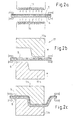
- Fig. 1a shows an inventive interior trim part 1 in section. It has a molded part 2, on which a support structure 3 in the form of a separate support member 4 is mounted.
- the molded part 2 comprises a wear layer 5, which forms a front side 1a of the interior trim part 1, and a carrier layer 6, which forms a back side 1b of the interior trim part 1.
- the wear layer 5 consists of a decorative film with thermoplastic properties.
- the carrier layer 6 has a soft elastic foam material. This has thermoplastic properties so that it can be transformed under heat and pressure.
- the carrier layer 6 is provided with a recess 7 for the support element 4. This has a support layer 8 and an additional cushion layer 9.
- the cushion layer 9 of the support element 4 extends in this embodiment through the recess 7 of the support layer 6 of the molding 2 and has direct contact with the wear layer 5 of the molding 2.
- the wear layer 5 is flexible. It can be elastic with an externally applied force together with the underlying cushion layer 9 deform and return to its neutral form when the force is removed.
- connecting elements 10 are attached to the carrier layer 6 of the molded part 2.
- the support element 4 has connection means 11, which mate with the connection elements 10 of the molded part 2.
- Each connecting element 10 is provided with a hat 10 a and a connecting shaft 10 b, which protrudes from the carrier layer 6 of the molded part 2.
- the connection means 11 have through openings 11a.
- the connecting stems 10b penetrate the through-openings 11a.
- a clamping element 12 is attached to the free end of the connecting shaft 10 b, which in Fig. 1b corresponds to clamping disc 12a shown in two views.
- FIGS. 2a to 2c represent an example of the prefabrication of a molded part 2.
- the carrier layer 6 and the wear layer 5 are first heated, as in Fig. 2a symbolized by a schematically illustrated upper heating coil 15 and a lower heating coil 16.
- the shaping takes place by means of a molding tool 17.
- Fig. 2b shows this mold 17 with a first upper mold part 17a and a second lower mold part 17b in the open state.
- the upper tool part 17a and the lower tool part 17b are moved towards each other.
- the closed tool parts 17a / 17b have given the material of the carrier layer 6 and the wear layer 5 a shape. After molding, the molded part 2 retains this shape.
- FIGS. 3a to 3c illustrate the further processing of in Fig. 2c recognizable molding 2 to which now still fasteners 10 must be attached.
- an injection mold 18 having a first upper tool part 18a and a second lower tool part 18b is used.
- the lower tool part 18b has two mold areas 19 on, which are each provided for producing a connecting element 10.
- Fig. 3b the closed state of the tool parts 18a / 18b is shown.
- thermoplastic material is injected.
- the thermoplastic material forms on the support layer 6 of the molded part 2, the connecting elements 10, namely two connecting fungi P.
- Each connecting mushroom P has a hat 10a, with which it is molded onto the carrier layer 6 of the molded part 2.
- a connecting stem 10 b is arranged, which protrudes from the support layer 6.
- the hat 10a facing the wear layer 5 has a hat edge 10c.
- the second tool part 18b is designed so that the foam of the carrier layer 6 is strongly compressed at the edge of the molding area 19, so that the thermoplastic injection molding material can not escape between the foam pores.
- the molded connecting mushroom P can reach at least at its edge of the door 10c as far as the wear layer 5 or it is only superficially connected to the support layer 6.
- FIG. 3c An embodiment of the molded part 2 with back-injected fasteners 10 shows Fig. 3c , Thereafter, the hat 10a of the connecting fungus P is adhered to the carrier layer 6 of the molded part 2 by adhesion.
- the foam material of the carrier layer 6 may remain compacted after the back injection. As a result, it has a smaller thickness among the connecting fungi P than beside the connecting fungi.
- FIGS. 4a and 4b The principle of mounting an interior trim part 1 is in the FIGS. 4a and 4b shown schematically.
- Fig. 4a The molded part 2 and the support member 4 are moved towards each other for the purpose of assembly. Again, the support member 4 on a support layer 8 and a cushion layer 9.
- the molding 2 differs from that in Fig. 1a shown molding 2, because its carrier layer 9 has no recess.
- the cushion layer 9 of the support element 4 thus has no contact with the wear layer 5 of the molded part 2. Instead, the cushion layer 9 touches the soft elastic carrier layer 6 of the molded part 2.
- the support layer 8 is provided with connection means 11 in the form of through openings 11a.
- the molded part 2 is provided with rear-injected connecting elements 10, which have a hat 10a and a connecting shaft 10b.
- the through-openings 11a of the support element 4 each fit on one of the connecting stems 10b of the molded part 2.
- An insertion connection is created according to FIG Fig. 4b , To secure this through-connection, in each case a clamping element 12 is attached to the free end of each connecting shaft 10b. This is a clamping disc, as in Fig. 1b shown.
- the clamping disc 12a clamped to the connecting shaft 10b and thereby prevents a movement apart of support element 4 and mold part. 2
- the cushion layer 9 of the support member 4 is pressed in the assembled state against the carrier layer 6 of the molded part 2. As a result, the carrier layer 6 and the cushion layer 9 are compressed and solid.
- the quality of the carrier layer 6 and the cushion layer 9 may be identical or different.
- the padding of the trim panel 1 may be desirably adjusted to provide a higher quality or a simpler interface for tactile perception.
- FIG. 5 Another embodiment of an interior trim part 1 is in Fig. 5 shown. Thereafter, the molded part 2 is formed with a wear layer 5 and a special carrier layer 6. It is provided a support structure 3, which has a separate support member 4, which is formed as a cushion layer 13. It is an interior trim part 1 with an armrest in the partial region of the support structure 3.
- the support layer 6 of the molded part 2 has a connecting means 10, which the formed as a cushion layer 13 support member 4 superimposed.
- the connecting means 10 is designed as a console element 14.
- the console element 14 carries the cushion layer 13. The latter is enclosed between the console element 14 and the wear layer 5 of the molded part 2.
- the carrier layer 6 also has a recess 7.
- the cushion layer 13 has direct contact with the wear layer 5 of the molded part 2.
Abstract
Description
Die Erfindung betrifft ein Innenverkleidungsteil für einen Fahrgastraum eines Fahrzeugs, mit einem Formteil, das eine Vorderseite aufweist, welche eine dekorative Nutzschicht des Innenverkleidungsteils bildet und mit wenigstens einer Trägerschicht, welche eine Rückseite des Innenverkleidungsteils bildet, wobei zumindest ein Teilbereich des Innenverkleidungsteils mit wenigstens einer Stützstruktur versehen ist, die eine angenehme taktile Wahrnehmung an der Oberfläche des Teilbereichs schafft.The invention relates to an interior trim part for a passenger compartment of a vehicle, comprising a molded part which has a front side which forms a decorative wear layer of the interior trim part and at least one carrier layer which forms a rear side of the interior trim part, wherein at least a partial region of the interior trim part having at least one support structure is provided, which creates a pleasant tactile perception on the surface of the sub-area.
Die Erfindung betrifft außerdem ein Verfahren zur Herstellung des Innenverkleidungsteils, wobei das Innenverkleidungsteil eine Vorderseite mit einer dekorativen Nutzschicht und darunter wenigstens eine Trägerschicht aufweist, welche die Rückseite bildet, und wobei zumindest ein Teilbereich des Innenverkleidungsteils mit einer Stützstruktur versehen ist, die eine angenehme taktile Wahrnehmung an der Oberfläche des Teilbereichs schafft, umfassend folgenden Schritt: Herstellen eines Formteils mit einer dekorativen Nutzschicht und wenigstens einer Trägerschicht.The invention also relates to a method for producing the interior trim part, wherein the interior trim part has a front side with a decorative wear layer and below at least one carrier layer which forms the rear side, and wherein at least a partial area of the interior trim part is provided with a support structure which provides a pleasant tactile perception on the surface of the partial area, comprising the following step: producing a molded part with a decorative wear layer and at least one carrier layer.
Die taktile Wahrnehmung ist die Sinneswahrnehmung über mechanische, thermische und schmerzempfindliche Rezeptoren der Nerven.The tactile perception is the sensory perception of mechanical, thermal and pain-sensitive receptors of the nerves.
Die Nutzschicht kann beispielsweise eine Oberfläche aufweisen, die mit einem ästhetischen Muster versehen ist. Häufig werden narbige Lederoberflächen, Holzmaserungen oder andere natürliche Materialoberflächen oder auch Textiloberflächen imitiert.The wear layer may, for example, have a surface provided with an aesthetic pattern. Often, scarred leather surfaces, wood grain or other natural material surfaces or textile surfaces are imitated.
Ein derartiges Innenverkleidungsteil wird vorzugsweise dort verwendet, wo ein Fahrgast im Betrieb des Fahrzeugs mit dem Innenverkleidungsteil in Berührung kommen kann. Beispielsweise kann eine Fahrzeugtür mit einem Innenverkleidungsteil versehen sein, das eine integrierte Armlehne aufweist. Das Innenverkleidungsteil kann auch eine ergonomische Funktion haben, wie es bei einer integrierten Armlehne der Fall ist, auf der sich der Fahrgast bequem abstützen können soll. Durch die Berührung gewinnt der Fahrgast eine taktile Wahrnehmung der Oberfläche des Innenverkleidungsteils. Weil er auch einen Druck auf die Oberfläche ausübt, ist unter der Oberfläche in der Regel eine Stützstruktur vorgesehen, welche die von außen einwirkende Kraft aufnehmen kann. Die Stützstruktur ist nachgiebig. Die Nachgiebigkeit ist für den Fahrgast ebenfalls fühlbar. Auf diese Weise vermittelt auch der unter der Oberfläche liegende Aufbau dem Fahrgast einen Sinneseindruck über die Qualität des Innenverkleidungsteils. Der Teilbereich des Innenverkleidungsteils, in dem eine taktile Wahrnehmung durch den Fahrgast erwartet wird, bildet eine Schnittstelle, an der die Sinneseindrücke erzeugt werden. Es ist bekannt, diesen Teilbereich des Innenverkleidungsteils mit einer Stützstruktur zu versehen, die weichelastisches Material enthält, beispielsweise Schaumstoff.Such an interior trim part is preferably used where a passenger can come into contact with the interior trim part during operation of the vehicle. For example, a vehicle door may be provided with an interior trim part having an integrated armrest. The interior trim part can also have an ergonomic function, as is the case with an integrated armrest, on which the passenger should be able to rest comfortably. The touch gives the passenger a tactile perception of the surface of the interior trim part. Because he also exerts pressure on the surface, a support structure is provided under the surface usually, which can absorb the externally applied force. The support structure is yielding. The flexibility is also felt by the passenger. In this way, the subsurface structure gives the passenger a sense of the quality of the interior trim part. The portion of the interior trim part in which a tactile perception is expected by the passenger, forms an interface at which the sensory impressions are generated. It is known to provide this portion of the interior trim part with a support structure containing soft elastic material, such as foam.
Aus der
Ein anderes Verfahren zur Herstellung von Innenverkleidungsteilen wird in der
Die bekannten Verfahren trachten danach, ein Innenverkleidungsteil mit möglichst wenigen Herstellschritten herzustellen und Kosten zu mindern.The known methods seek to produce an interior trim part with as few manufacturing steps and reduce costs.
Der Erfindung liegt die Aufgabe zugrunde, ein alternatives Innenverkleidungsteil für einen Fahrgastraum eines Fahrzeugs vorzuschlagen, das mit verringertem technischem Aufwand herstellbar ist, sowie ein Verfahren vorzuschlagen, mit dem das Innenverkleidungsteil herstellbar ist.The invention has for its object to propose an alternative interior trim part for a passenger compartment of a vehicle, which can be produced with reduced technical effort, and to propose a method by which the interior trim part can be produced.
Erfindungsgemäß wird die Aufgabe dadurch gelöst, dass das Formteil wenigstens ein Verbindungselement aufweist, welches an der Trägerschicht der Rückseite des Innenverkleidungsteils angebracht ist, dass die Stützstruktur als separates Stützelement ausgebildet und von dem Verbindungselement des Formteils gehalten ist.According to the invention the object is achieved in that the molded part has at least one connecting element which is attached to the carrier layer of the back of the interior trim part, that the support structure is formed as a separate support member and held by the connecting element of the molded part.
Das Verbindungsmittel des Formteils kann während der Herstellung des Formteils im selben Schritt hergestellt werden oder in einem späteren Schritt an das Formteil angefügt werden.The connecting means of the molded part can be produced during the production of the molded part in the same step or attached to the molded part in a later step.
Um das Anschlussmittel des Stützelements mit dem Verbindungselement des Formteils zu verbinden, sind unterschiedliche Methoden einsetzbar, beispielsweise Schweißen, Verrasten, Klemmen, Schrauben oder Kleben. Für jede der erwähnten Verbindungsarten können das Anschlussmittel sowie das Verbindungselement in besonderer Weise gestaltet sein, damit die gewünschte Verbindungsmethode begünstigt wird. Gegebenenfalls kann ein zusätzliches Element, beispielsweise eine Gewindemutter für eine Schraubverbindung, ein Klemmelement für eine Klemmverbindung oder ein Rastelement für eine Rastverbindung vorgesehen sein.In order to connect the connecting means of the support element with the connecting element of the molded part, different methods can be used, for example welding, latching, clamping, screwing or gluing. For each of the mentioned types of connection, the connection means and the connection element can be designed in a special way, so that the desired connection method is favored. Optionally, an additional element, for example a threaded nut for a screw connection, a clamping element for a clamping connection or a locking element for a latching connection can be provided.
Das erfindungsgemäße Verfahren zur Herstellung umfasst folgende weitere Schritte: Einlegen des fertigen Formteils in ein Spritzgießwerkzeug, Anbringen wenigstens eines Verbindungselements in dem Teilbereich an der Rückseite des Innenverkleidungsteils durch Hinterspritzung der Trägerschicht mittels des Spritzgießwerkzeugs, Entnahme des hinterspritzten Formteils aus dem Spritzgießwerkzeug, Herstellen einer Stützstruktur als separates Stützelement mit wenigstens einem Anschlussmittel, passend zu dem an der Trägerschicht angebrachten Verbindungselement des Formteils, und Montage des Stützelements an dem Formteil durch Verbindung des Anschlussmittels des Stützelements mit dem Verbindungselement des Formteils.The inventive method for production comprises the following further steps: inserting the finished molded part in an injection mold, attaching at least one connecting element in the portion at the back of the interior trim part by injection molding of the backing layer by means of the injection mold, removal of the back-injected molded part from the injection mold, producing a support structure as separate support member having at least one connection means, matching the attached to the carrier layer connecting element of the molding, and mounting the support member to the molded part by connecting the connecting means of the support member with the connecting element of the molding.
Das vorgeschlagene Innenverkleidungsteil umfasst mehrere Bauteile. Ein Bauteil ist das vorgefertigte Formteil. Dieses bildet die Vorderseite des Innenverkleidungsteils. Es ist daher für die Ästhetik maßgeblich. Außerdem ist wenigstens ein weiteres Bauteil, nämlich das vorgefertigte Stützelement vorgesehen, das maßgeblich die Qualität desjenigen Teilbereichs beeinflusst, der für die taktile Wahrnehmung vorgesehen ist. Das Formteil ist das größere der Bauteile. Der Vorteil des mehrteiligen Aufbaus besteht darin, für das Formteil stets dieselben Herstellwerkzeuge verwenden zu können.The proposed interior trim part comprises several components. One component is the prefabricated molded part. This forms the front of the interior trim part. It is therefore decisive for the aesthetics. In addition, at least one further component, namely the prefabricated support element is provided, which decisively influences the quality of that portion intended for the tactile perception. The molded part is the larger of the components. The advantage of the multi-part construction is that it can always use the same production tools for the molded part.
Das Formteil kann auf unterschiedliche Weise erzeugt werden, beispielsweise durch Spritzgießen eines thermoplastischen Trägerschichtmaterials gegen die Nutzschicht. Dazu wird zunächst die Nutzschicht in einen Formhohlraum eines Spritzgießwerkzeugs eingelegt und anschließend das thermoplastische Trägerschichtmaterial in den Formhohlraum eingespritzt. Dabei entsteht eine gleichmäßige Anbindung des Trägerschichtmaterials an der Nutzschicht. Eine andere Methode ist das Reaktionsspritzgießen. Dabei wird beispielsweise ein schäumendes Trägerschichtmaterial in einen Formhohlraum eines Spritzgießwerkzeugs geleitet. Das schäumende Trägerschichtmaterial reagiert und expandiert in dem Formhohlraum. Auch hierbei ist zuvor eine Nutzschicht in den Formhohlraum eingelegt worden. Auch dabei entsteht eine gleichmäßige Anbindung des geschäumten Trägerschichtmaterials an der Nutzschicht. Außerdem kann jedes andere geeignete Verfahren verwendet werden, um das Formteil herzustellen. Wenn das Verbindungselement nicht bereits während der Herstellung des Formteils erzeugt worden ist, muss gewährleistet sein, dass sich das vorgefertigte Formteil eignet, um später ein Verbindungselement an seiner Rückseite anbringen zu können, beispielsweise durch Hinterspritzung in einem dafür vorgesehenen Spritzgießwerkzeug.The molded part can be produced in different ways, for example by injection molding a thermoplastic carrier layer material against the wear layer. For this purpose, first the wear layer is placed in a mold cavity of an injection mold and then the thermoplastic carrier layer material is injected into the mold cavity. This results in a uniform connection of the carrier layer material to the wear layer. Another method is reaction injection molding. In this case, for example, a foaming carrier layer material is passed into a mold cavity of an injection mold. The foaming backsheet material reacts and expands in the mold cavity. Here, too, a wear layer has previously been inserted into the mold cavity. This also results in a uniform connection of the foamed carrier layer material to the wear layer. In addition, any other suitable method can be used to make the molded article. If the connecting element has not already been produced during the production of the molded part, it must be ensured that the prefabricated molded part is suitable for later attachment of a connecting element on its rear side, for example by injection-molding in an injection molding tool provided therefor.
Das kleinere Bauteil, nämlich das Stützelement, kann in mehreren Varianten hergestellt werden, die jeweils unterschiedliche Qualitäten aufweisen. Ein wichtiges Qualitätsmerkmal des Innenverkleidungsteils ist die Nachgiebigkeit und Festigkeit desjenigen Teilbereichs, der für eine Berührung durch den Fahrgast vorgesehen ist. Das an der Rückseite dieses Teilbereichs des Innenverkleidungsteils angebrachte Stützelement hat dabei einen großen Einfluss auf die taktile Wahrnehmung durch den Fahrgast.The smaller component, namely the support element, can be produced in several variants, each having different qualities. An important quality feature of the trim panel is the compliance and strength of that portion intended to be touched by the passenger. The attached to the back of this portion of the interior trim part support element has a great influence on the tactile perception by the passenger.
Der mehrteilige Aufbau erlaubt es, Stützelemente unterschiedlicher Nachgiebigkeit mit immer demselben Formteil zu kombinieren. So kann für Fahrzeuge, die eine Luxusausstattung erhalten sollen, ein aufwändiges Stützelement vorgesehen werden, während für ein Fahrzeug, das eine Grundausstattung erhalten soll, ein einfach aufgebautes Stützelement genügt.The multi-part construction makes it possible to combine support elements of different compliance with always the same molded part. Thus, for vehicles that are to receive luxury equipment, a complex support element can be provided while For a vehicle that is to receive a basic equipment, a simply constructed support element is sufficient.
Günstigerweise weist das Verbindungselement thermoplastisches Material auf und das thermoplastische Material ist durch Hinterspritzung auf der Rückseite des Innenverkleidungsteils mit dem Formteil verbunden.Conveniently, the connecting element comprises thermoplastic material and the thermoplastic material is connected by injection-molding on the back of the interior trim part with the molding.
In einer besonders einfachen Ausführung weist das Stützelement wenigstens eine Stützschicht auf. Das Stützelement bietet einen festen Unterbau unterhalb der Nutzschicht des Innenverkleidungsteils. Die Stützschicht kann starr ausgebildet sein, um den festigenden Effekt zu begünstigen.In a particularly simple embodiment, the support element has at least one support layer. The support element provides a solid foundation below the wear layer of the interior trim part. The support layer may be rigid in order to favor the setting effect.
Hilfreich ist es, wenn das Stützelement wenigstens ein Anschlussmittel aufweist, das mit dem Verbindungselement des Formteils zusammenpasst.It is helpful if the support element has at least one connection means which mates with the connection element of the molding.
Eine Weiterbildung des Innenverkleidungsteils sieht vor, dass das mit der Stützschicht versehene Stützelement zusätzlich mit wenigstens einer Polsterschicht versehen ist. Die Polsterschicht ist auf jener Seite der Stützschicht angeordnet, die im montierten Zustand dem Formteil zugewandt ist. Während der Montage des Stützelements an dem Formteil wird die Polsterschicht mit dem Formteil in Kontakt gebracht. Dabei können die Kontaktflächen zusätzlich miteinander verbunden sein, beispielsweise stoffschlüssig durch Schweißen oder Kleben. In dem Teilbereich, in dem die Polsterschicht mit dem Formteil in Kontakt kommt, kann die Trägerschicht des Formteils eine Aussparung aufweisen, damit die Polsterschicht des Stützelements unmittelbar an der Nutzschicht des Formteils anliegt.A development of the interior trim part provides that the supporting element provided with the support layer is additionally provided with at least one cushion layer. The cushion layer is arranged on that side of the support layer which, in the mounted state, faces the molded part. During assembly of the support member to the molding, the cushion layer is brought into contact with the molding. In this case, the contact surfaces may additionally be connected to one another, for example by material bonding by welding or gluing. In the partial area in which the cushion layer comes into contact with the molded part, the carrier layer of the molded part may have a recess, so that the cushion layer of the support element bears directly against the wear layer of the molded part.
Es können Stützelemente hergestellt werden, deren Polsterschichten unterschiedlich dimensioniert sind, insbesondere unterschiedliche Dicke aufweisen. Damit können dann Innenverkleidungsteile mit variierender Polsterungsqualität erzeugt werden. Des Weiteren kann die Konstruktion so ausgelegt sein, dass die Polsterschicht des Stützelements im montierten Zustand komprimiert ist. Dadurch wird eine feste Polsterung erhalten. Das Maß an Komprimierung sowie auch die Polsterdicke können variiert werden, wodurch eine Vielzahl an Kombinationsmöglichkeiten entsteht.It can support elements are produced, the cushion layers are dimensioned differently, in particular have different thickness. This can then interior trim parts produced with varying padding quality become. Furthermore, the construction may be designed so that the cushion layer of the support member is compressed in the assembled state. As a result, a firm padding is obtained. The amount of compression as well as the cushion thickness can be varied, creating a variety of possible combinations.
Auch die Trägerschicht des Formteils kann ein weichelastisches Material aufweisen. Wenn diese Trägerschicht mit einem Stützelement kombiniert wird, das mit einer Polsterschicht versehen ist, können die weichelastischen Eigenschaften der Trägerschicht (Formteil) und die weichelastischen Eigenschaften der Polsterschicht (Stützelement) aufeinander abgestimmt werden. Durch die Wahl unterschiedlicher weichelastischer Eigenschaften kann die Polsterqualität eingestellt werden. Selbstverständlich können die weichelastischen Eigenschaften von Polsterschicht und Trägerschicht auch identisch sein.Also, the carrier layer of the molding may have a soft elastic material. When this support layer is combined with a support element provided with a cushion layer, the soft elastic properties of the support layer (molding) and the soft elastic properties of the cushion layer (support element) can be matched. By choosing different soft elastic properties, the upholstery quality can be adjusted. Of course, the soft elastic properties of the cushion layer and carrier layer can also be identical.
Um eine einfache Montage zu ermöglichen, weist das hinterspritzte Verbindungselement die Gestalt eines Verbindungspilzes auf, mit einem Hut, welcher der Trägerschicht zugewandt und mit dieser verbunden ist, sowie mit einem Verbindungsstiel, der von der Trägerschicht abgewandt ist und von dieser hervorsteht. Der Verbindungspilz ist Teil einer Steckverbindung. Das zweite Teil der Steckverbindung bildet das Anschlussmittel des Stützelements. Das Anschlussmittel ist komplementär gestaltet und ist vorzugsweise mit dem Verbindungspilz verrastbar.In order to enable simple assembly, the back-injected connecting element has the shape of a connecting mushroom, with a hat, which faces the support layer and is connected thereto, as well as with a connecting handle, which faces away from the support layer and protrudes therefrom. The connecting mushroom is part of a plug connection. The second part of the connector forms the connection means of the support element. The connecting means is designed to be complementary and is preferably latched to the connecting mushroom.
Nachstehend sind Ausführungsbeispiele des erfindungsgemäßen Innenverkleidungsteils beispielhaft dargestellt sowie ein Verfahren zur seiner Herstellung anhand mehrerer schematischer Figuren detailliert beschrieben. Identische Merkmale der Ausführungsbeispiele sind mit den gleichen Bezugszeichen versehen. Es zeigen:
- Fig. 1
- ein Innenverkleidungsteil umfassend ein Formteil
- Fig. 2a-c
- sowie ein daran montiertes separates Stützelement, drei Schritte der Vorfertigung eines Formteils,
- Fig. 3a-b
- zwei Schritte zur Anbringung von Verbindungselemen- ten an das vorgefertigte Formteil mittels eines Spritzgießwerkzeugs,
- Fig. 3c
- das Formteil gemäß
Fig. 3b aus dem Spritzgießwerk- zeug entnommen, - Fig. 4a-b
- die Montage eines separaten Stützelements an das Formteil gemäß
Fig. 4 , - Fig. 5
- eine alternative Ausführung eines Innenverkleidungs- teils.
- Fig. 1
- an interior trim part comprising a molding
- Fig. 2a-c
- and a separate support element mounted thereon, three steps of prefabrication of a molding,
- Fig. 3a-b
- two steps for attaching connecting elements to the prefabricated molded part by means of an injection molding tool,
- Fig. 3c
- the molding according to
Fig. 3b taken from the injection mold, - Fig. 4a-b
- the assembly of a separate support member to the molding according to
Fig. 4 . - Fig. 5
- an alternative embodiment of a Innenverkleidungs- part.
Das Formteil 2 umfasst eine Nutzschicht 5, welche eine Vorderseite 1a des Innenverkleidungsteils 1 bildet und eine Trägerschicht 6, welche eine Rückseite 1b des Innenverkleidungsteils 1 bildet. Die Nutzschicht 5 besteht aus einer dekorativen Folie mit thermoplastischen Eigenschaften. Die Trägerschicht 6 weist ein weichelastisches Schaumstoffmaterial auf. Dieses hat thermoplastische Eigenschaften, damit es unter Wärme und Druck umgeformt werden kann. Die Trägerschicht 6 ist mit einer Aussparung 7 für das Stützelement 4 versehen. Dieses weist eine Stützschicht 8 und eine zusätzliche Polsterschicht 9 auf. Die Polsterschicht 9 des Stützelements 4 reicht bei diesem Ausführungsbeispiel durch die Aussparung 7 der Trägerschicht 6 des Formteils 2 hindurch und hat unmittelbaren Kontakt mit der Nutzschicht 5 des Formteils 2. Die Nutzschicht 5 ist nachgiebig. Sie kann sich bei einer von außen einwirkenden Kraft gemeinsam mit der darunterliegenden Polsterschicht 9 elastisch verformen und bei Wegnahme der Kraft in ihre neutrale Gestalt zurückkehren.The molded
Zwecks Verbindung des Stützelements 4 an dem Formteil 2 sind Verbindungselemente 10 an der Trägerschicht 6 des Formteils 2 angebracht. Das Stützelement 4 weist Anschlussmittel 11 auf, die mit den Verbindungselementen 10 des Formteils 2 zusammenpassen. Jedes Verbindungselement 10 ist mit einem Hut 10a und einem Verbindungsstiel 10b versehen, der von der Trägerschicht 6 des Formteils 2 hervorsteht. Die Anschlussmittel 11 weisen Durchstecköffnungen 11a auf. Die Verbindungsstiele 10b durchdringen die Durchstecköffnungen 11a. Zur Sicherung der zusammengesteckten Durchsteckverbindung ist an dem freien Ende des Verbindungsstiels 10b jeweils ein Klemmelement 12 befestigt, welches der in
Die
Die
Ein Ausführungsbeispiel für das ausgeformte Formteil 2 mit hinterspritzten Verbindungselementen 10 zeigt
Das Prinzip der Montage eines Innenverkleidungsteils 1 ist in den
Nach
Die Stützschicht 8 ist mit Anschlussmitteln 11 in Form von Durchstecköffnungen 11a versehen. Das Formteil 2 ist mit hinterspritzten Verbindungselementen 10 versehen, die einen Hut 10a und einen Verbindungsstiel 10b aufweisen. Die Durchstecköffnungen 11a des Stützelements 4 passen jeweils auf einen der Verbindungsstiele 10b des Formteils 2. Es entsteht eine Durchsteckverbindung gemäß
Die Polsterschicht 9 des Stützelements 4 ist im montierten Zustand gegen die Trägerschicht 6 des Formteils 2 gedrückt. Dadurch werden die Trägerschicht 6 und die Polsterschicht 9 verdichtet und fester.The
Die Qualität der Trägerschicht 6 und der Polsterschicht 9 können identisch oder unterschiedlich sein. Durch geeignete Wahl und Kombination dieser beiden Schichten kann die Polsterung des Innenverkleidungsteils 1 in gewünschter Weise angepasst sein, um eine qualitativ höherwertige oder eine einfachere Schnittstelle für die taktile Wahrnehmung zu bilden.The quality of the
Ein weiteres Ausführungsbeispiel eines Innenverkleidungsteils 1 ist in
- 11
- InnenverkleidungsteilInterior trim part
- 22
- Formteilmolding
- 33
- Stützstruktursupport structure
- 44
- Stützelementsupport element
- 55
- Nutzschichtwear layer
- 66
- Trägerschichtbacking
- 77
- Aussparungrecess
- 88th
- Stützschichtbacking
- 99
- Polsterschichtcushion layer
- 1010
- Verbindungselementconnecting element
- 10a10a
- Hutcap
- 10b10b
- Verbindungsstielconnecting stalk
- 1111
- Anschlussmittelconnection means
- 11a11a
- DurchstecköffnungThrough opening
- 1212
- Klemmelementclamping element
- 12a12a
- Klemmscheibeclamping disc
- 1313
- Polsterschichtcushion layer
- 1414
- Konsolenelementconsole element
- 1515
- Heizwendelheating coil
- 1616
- Heizwendelheating coil
- 1717
- Formwerkzeugmold
- 17a17a
- Erstes oberes WerkzeugteilFirst upper tool part
- 17b17b
- Zweites unteres WerkzeugteilSecond lower tool part
- 1818
- Spritzgießwerkzeuginjection mold
- 18a18a
- Erstes oberes WerkzeugteilFirst upper tool part
- 18b18b
- Zweites unteres WerkzeugteilSecond lower tool part
- 1919
- Formbereichshape area
Claims (8)
Priority Applications (4)
| Application Number | Priority Date | Filing Date | Title |
|---|---|---|---|
| EP09170812A EP2298606B1 (en) | 2009-09-21 | 2009-09-21 | Interior cladding part for a vehicle passenger area and production method |
| AT09170812T ATE532672T1 (en) | 2009-09-21 | 2009-09-21 | INTERIOR TRIM PART FOR A PASSENGER COMPARTMENT OF A VEHICLE AND METHOD FOR PRODUCING SAME |
| US12/886,053 US8297675B2 (en) | 2009-09-21 | 2010-09-20 | Interior trim part for a passenger compartment of a vehicle, and method for producing an interior trim part |
| CN201010290901.0A CN102019883B (en) | 2009-09-21 | 2010-09-21 | Interior cladding part for a vehicle passenger area and production method |
Applications Claiming Priority (1)
| Application Number | Priority Date | Filing Date | Title |
|---|---|---|---|
| EP09170812A EP2298606B1 (en) | 2009-09-21 | 2009-09-21 | Interior cladding part for a vehicle passenger area and production method |
Publications (2)
| Publication Number | Publication Date |
|---|---|
| EP2298606A1 true EP2298606A1 (en) | 2011-03-23 |
| EP2298606B1 EP2298606B1 (en) | 2011-11-09 |
Family
ID=41129100
Family Applications (1)
| Application Number | Title | Priority Date | Filing Date |
|---|---|---|---|
| EP09170812A Active EP2298606B1 (en) | 2009-09-21 | 2009-09-21 | Interior cladding part for a vehicle passenger area and production method |
Country Status (4)
| Country | Link |
|---|---|
| US (1) | US8297675B2 (en) |
| EP (1) | EP2298606B1 (en) |
| CN (1) | CN102019883B (en) |
| AT (1) | ATE532672T1 (en) |
Cited By (1)
| Publication number | Priority date | Publication date | Assignee | Title |
|---|---|---|---|---|
| WO2021052781A1 (en) * | 2019-09-20 | 2021-03-25 | Renault S.A.S | Motor vehicle trim panel made of expanded polymer material |
Families Citing this family (9)
| Publication number | Priority date | Publication date | Assignee | Title |
|---|---|---|---|---|
| US8377368B2 (en) * | 2009-12-11 | 2013-02-19 | Ti Automotive Technology Center Gmbh | Component mounting arrangement |
| DE102009060338A1 (en) * | 2009-12-23 | 2011-06-30 | Polytec Automotive GmbH & Co. KG, 82538 | Covering parts of motor vehicles |
| US8632117B1 (en) * | 2012-07-26 | 2014-01-21 | GM Global Technology Operations LLC | Armrest assemblies for vehicle doors |
| EP2708409B1 (en) * | 2012-09-14 | 2015-07-01 | Grupo Antolin-Ingenieria, S.A. | Self-supported cushion assembly for an interior vehicle part |
| US9193247B2 (en) * | 2012-10-05 | 2015-11-24 | Ford Global Technologies, Llc | Vehicle door trim panel shut face feature to reduce deflection |
| US8844993B1 (en) * | 2013-09-04 | 2014-09-30 | Nissan North America, Inc. | Reinforced vehicle trim assembly |
| US11360258B1 (en) * | 2016-06-01 | 2022-06-14 | Apple Inc. | Illuminated input devices |
| CN110612226B (en) * | 2017-06-02 | 2023-07-28 | 丰田纺织株式会社 | Decorative plate for vehicle door and door decorative plate |
| JP6676092B2 (en) * | 2018-03-28 | 2020-04-08 | 株式会社豊田自動織機 | Body reinforcing structure and method of manufacturing body reinforcing structure |
Citations (6)
| Publication number | Priority date | Publication date | Assignee | Title |
|---|---|---|---|---|
| US6248200B1 (en) * | 1996-05-28 | 2001-06-19 | Chrysler Corporation | Method of making a trim panel assembly including integral arm rest portion |
| EP1287961A2 (en) | 2001-09-04 | 2003-03-05 | R+S Technik GmbH | Trim component as well as production method and apparatus for making a multilayer trim component |
| FR2855782A1 (en) * | 2003-02-07 | 2004-12-10 | Volkswagen Ag | METHOD FOR MANUFACTURING A COATING ELEMENT IN COMPOSITE MATERIAL, AND INTERIOR COATING ELEMENT FOR A MOTOR VEHICLE OBTAINED BY THIS PROCESS |
| DE102004023823B4 (en) | 2003-05-16 | 2005-12-08 | Lear Corp., Southfield | Method for producing a vehicle interior trim with integrated soft-touch armrest |
| DE102004025570A1 (en) * | 2004-05-25 | 2005-12-15 | Adam Opel Ag | Plastic automobile part manufacture incorporating foamed components involves joining prefabricated supporting and foam parts and adding skin layer to outside |
| FR2886571A1 (en) * | 2005-06-06 | 2006-12-08 | Faurecia Interieur Ind Snc | METHOD FOR PRODUCING AN INTERIOR EQUIPMENT PIECE OF A MOTOR VEHICLE AND PART THEREOF |
Family Cites Families (12)
| Publication number | Priority date | Publication date | Assignee | Title |
|---|---|---|---|---|
| US5082609A (en) * | 1990-10-22 | 1992-01-21 | Bridgestone Australia Ltd. | Method of forming a moulded panel |
| US5304273A (en) * | 1992-09-21 | 1994-04-19 | General Motors Corporation | Method for manufacture of two-tone vehicle trim panel |
| US5401449A (en) * | 1993-07-12 | 1995-03-28 | General Motors Corporation | Method of manufacturing a trim panel having a styling line |
| US5885662A (en) * | 1997-01-31 | 1999-03-23 | Atoma International, Inc. | Decorative automotive interior trim articles with integral light stable polyurethane elastomer covering and process for making the same |
| JP4297982B2 (en) * | 1997-04-18 | 2009-07-15 | アトマ インターナショナル インコーポレイテッド | Process for producing automotive interior panel-like structure and products including automotive interior panel-like structure |
| MY127292A (en) * | 2001-01-30 | 2006-11-30 | Sumitomo Chemical Co | Thermoplastic resin foam molding. |
| AT5191U1 (en) * | 2001-03-07 | 2002-04-25 | Steyr Daimler Puch Ag | FASTENING ELEMENT FOR A FAIRING PART INSIDE A MOTOR VEHICLE |
| JP4135917B2 (en) * | 2003-07-11 | 2008-08-20 | 河西工業株式会社 | Manufacturing method of automotive interior parts and molding die |
| WO2005039857A1 (en) * | 2003-10-16 | 2005-05-06 | Johnson Controls Technology Company | Vehicle component and method for making a vehicle component |
| US7425029B2 (en) * | 2005-01-12 | 2008-09-16 | Lear Corporation | Integral cushioned trim panel for a vehicle |
| CN1840310A (en) * | 2005-03-30 | 2006-10-04 | 河西工业株式会社 | Interior decoration part for automobile and method for manufacturing the same |
| JP5023538B2 (en) * | 2006-04-11 | 2012-09-12 | 日産自動車株式会社 | Automotive interior trim |
-
2009
- 2009-09-21 AT AT09170812T patent/ATE532672T1/en active
- 2009-09-21 EP EP09170812A patent/EP2298606B1/en active Active
-
2010
- 2010-09-20 US US12/886,053 patent/US8297675B2/en active Active
- 2010-09-21 CN CN201010290901.0A patent/CN102019883B/en active Active
Patent Citations (6)
| Publication number | Priority date | Publication date | Assignee | Title |
|---|---|---|---|---|
| US6248200B1 (en) * | 1996-05-28 | 2001-06-19 | Chrysler Corporation | Method of making a trim panel assembly including integral arm rest portion |
| EP1287961A2 (en) | 2001-09-04 | 2003-03-05 | R+S Technik GmbH | Trim component as well as production method and apparatus for making a multilayer trim component |
| FR2855782A1 (en) * | 2003-02-07 | 2004-12-10 | Volkswagen Ag | METHOD FOR MANUFACTURING A COATING ELEMENT IN COMPOSITE MATERIAL, AND INTERIOR COATING ELEMENT FOR A MOTOR VEHICLE OBTAINED BY THIS PROCESS |
| DE102004023823B4 (en) | 2003-05-16 | 2005-12-08 | Lear Corp., Southfield | Method for producing a vehicle interior trim with integrated soft-touch armrest |
| DE102004025570A1 (en) * | 2004-05-25 | 2005-12-15 | Adam Opel Ag | Plastic automobile part manufacture incorporating foamed components involves joining prefabricated supporting and foam parts and adding skin layer to outside |
| FR2886571A1 (en) * | 2005-06-06 | 2006-12-08 | Faurecia Interieur Ind Snc | METHOD FOR PRODUCING AN INTERIOR EQUIPMENT PIECE OF A MOTOR VEHICLE AND PART THEREOF |
Cited By (2)
| Publication number | Priority date | Publication date | Assignee | Title |
|---|---|---|---|---|
| WO2021052781A1 (en) * | 2019-09-20 | 2021-03-25 | Renault S.A.S | Motor vehicle trim panel made of expanded polymer material |
| FR3101037A1 (en) * | 2019-09-20 | 2021-03-26 | Renault S.A.S | AUTOMOTIVE VEHICLE TRIM PANEL IN EXPANDED POLYMERIC MATERIAL |
Also Published As
| Publication number | Publication date |
|---|---|
| EP2298606B1 (en) | 2011-11-09 |
| US20110068596A1 (en) | 2011-03-24 |
| US8297675B2 (en) | 2012-10-30 |
| CN102019883B (en) | 2015-04-22 |
| CN102019883A (en) | 2011-04-20 |
| ATE532672T1 (en) | 2011-11-15 |
Similar Documents
| Publication | Publication Date | Title |
|---|---|---|
| EP2298606B1 (en) | Interior cladding part for a vehicle passenger area and production method | |
| DE19654246B4 (en) | Interior fitting for motor vehicles | |
| DE102005053477B4 (en) | Automotive interior trim assembly and related method | |
| DE10124036C2 (en) | Trim part on the side facing the interior of a body part of motor vehicles | |
| DE19851117C5 (en) | Method for producing a molded part | |
| DE102006001663A1 (en) | United, padded interior trim panel for a vehicle | |
| DE102004041384A1 (en) | Two-stage shapes with optional soft padding | |
| DE102006033059A1 (en) | Headrest for a motor vehicle, comprises an injection moulded carrier from a hard component and a covering layer from a soft component having a structured surface arranged on the Headrest | |
| DE102007059233A1 (en) | Molding as paneling/decorative parts for a vehicle's interior has a decorative layer, two soft layers one under the decorative layer and a hard supporter | |
| EP1151841B1 (en) | Interior lether liner for a vehicle and a method for manufacturing the same | |
| DE10159814B4 (en) | Method for producing a heated interior trim part and heated interior trim part | |
| DE202007017218U1 (en) | Molded part with wood veneer as decorative layer, in particular decorative part and / or trim part for a vehicle interior, with a soft layer | |
| DE10218004B3 (en) | Manufacture of an interior part and interior part | |
| DE102015117462A1 (en) | CLADDING COMPONENT AND METHOD FOR PRODUCING A COATING COMPONENT | |
| DE10211683A1 (en) | Trim part, in particular for a motor vehicle, and method for its production | |
| DE10305064A1 (en) | Method of manufacturing a cladding element | |
| AT509944B1 (en) | COMPONENT | |
| DE102010037022B4 (en) | Device and method for producing a molded part with a three-dimensionally structured surface | |
| DE102008051978A1 (en) | Interior part for vehicle, has gel mass or gel component having gel mass, where gel component is integrated in carrier material, particularly foam material, which has smaller indulgence as gel component | |
| EP3463974B1 (en) | Back rest panel and method for producing same | |
| DE202008017784U1 (en) | Interior trim part with absorbent decor material | |
| EP4070681B1 (en) | Orthopaedic shoe insert sole blank | |
| EP1257402B1 (en) | Method for producing a plastic composite element, and plastic composite element | |
| DE102007042427A1 (en) | Molded part producing method, involves foam coating core element with plastic material, removing core element afterwards from molded part, and shredding core element by applying compressive force | |
| DE102018118426A1 (en) | METHOD AND SYSTEM FOR USING AN OPEN INJECTION MOLDING PROCESS WITH A SINGLE TOOL FOR COVERING COMPONENTS |
Legal Events
| Date | Code | Title | Description |
|---|---|---|---|
| PUAI | Public reference made under article 153(3) epc to a published international application that has entered the european phase |
Free format text: ORIGINAL CODE: 0009012 |
|
| AK | Designated contracting states |
Kind code of ref document: A1 Designated state(s): AT BE BG CH CY CZ DE DK EE ES FI FR GB GR HR HU IE IS IT LI LT LU LV MC MK MT NL NO PL PT RO SE SI SK SM TR |
|
| 17P | Request for examination filed |
Effective date: 20110329 |
|
| GRAP | Despatch of communication of intention to grant a patent |
Free format text: ORIGINAL CODE: EPIDOSNIGR1 |
|
| RIC1 | Information provided on ipc code assigned before grant |
Ipc: B60R 13/02 20060101AFI20110516BHEP |
|
| GRAS | Grant fee paid |
Free format text: ORIGINAL CODE: EPIDOSNIGR3 |
|
| GRAA | (expected) grant |
Free format text: ORIGINAL CODE: 0009210 |
|
| AK | Designated contracting states |
Kind code of ref document: B1 Designated state(s): AT BE BG CH CY CZ DE DK EE ES FI FR GB GR HR HU IE IS IT LI LT LU LV MC MK MT NL NO PL PT RO SE SI SK SM TR |
|
| REG | Reference to a national code |
Ref country code: GB Ref legal event code: FG4D Free format text: NOT ENGLISH |
|
| REG | Reference to a national code |
Ref country code: CH Ref legal event code: EP |
|
| REG | Reference to a national code |
Ref country code: IE Ref legal event code: FG4D Free format text: LANGUAGE OF EP DOCUMENT: GERMAN |
|
| REG | Reference to a national code |
Ref country code: DE Ref legal event code: R096 Ref document number: 502009001880 Country of ref document: DE Effective date: 20120112 |
|
| REG | Reference to a national code |
Ref country code: NL Ref legal event code: VDEP Effective date: 20111109 |
|
| LTIE | Lt: invalidation of european patent or patent extension |
Effective date: 20111109 |
|
| PG25 | Lapsed in a contracting state [announced via postgrant information from national office to epo] |
Ref country code: IS Free format text: LAPSE BECAUSE OF FAILURE TO SUBMIT A TRANSLATION OF THE DESCRIPTION OR TO PAY THE FEE WITHIN THE PRESCRIBED TIME-LIMIT Effective date: 20120309 Ref country code: NO Free format text: LAPSE BECAUSE OF FAILURE TO SUBMIT A TRANSLATION OF THE DESCRIPTION OR TO PAY THE FEE WITHIN THE PRESCRIBED TIME-LIMIT Effective date: 20120209 Ref country code: LT Free format text: LAPSE BECAUSE OF FAILURE TO SUBMIT A TRANSLATION OF THE DESCRIPTION OR TO PAY THE FEE WITHIN THE PRESCRIBED TIME-LIMIT Effective date: 20111109 |
|
| PG25 | Lapsed in a contracting state [announced via postgrant information from national office to epo] |
Ref country code: HR Free format text: LAPSE BECAUSE OF FAILURE TO SUBMIT A TRANSLATION OF THE DESCRIPTION OR TO PAY THE FEE WITHIN THE PRESCRIBED TIME-LIMIT Effective date: 20111109 Ref country code: LV Free format text: LAPSE BECAUSE OF FAILURE TO SUBMIT A TRANSLATION OF THE DESCRIPTION OR TO PAY THE FEE WITHIN THE PRESCRIBED TIME-LIMIT Effective date: 20111109 Ref country code: PL Free format text: LAPSE BECAUSE OF FAILURE TO SUBMIT A TRANSLATION OF THE DESCRIPTION OR TO PAY THE FEE WITHIN THE PRESCRIBED TIME-LIMIT Effective date: 20111109 Ref country code: GR Free format text: LAPSE BECAUSE OF FAILURE TO SUBMIT A TRANSLATION OF THE DESCRIPTION OR TO PAY THE FEE WITHIN THE PRESCRIBED TIME-LIMIT Effective date: 20120210 Ref country code: SE Free format text: LAPSE BECAUSE OF FAILURE TO SUBMIT A TRANSLATION OF THE DESCRIPTION OR TO PAY THE FEE WITHIN THE PRESCRIBED TIME-LIMIT Effective date: 20111109 Ref country code: NL Free format text: LAPSE BECAUSE OF FAILURE TO SUBMIT A TRANSLATION OF THE DESCRIPTION OR TO PAY THE FEE WITHIN THE PRESCRIBED TIME-LIMIT Effective date: 20111109 Ref country code: SI Free format text: LAPSE BECAUSE OF FAILURE TO SUBMIT A TRANSLATION OF THE DESCRIPTION OR TO PAY THE FEE WITHIN THE PRESCRIBED TIME-LIMIT Effective date: 20111109 Ref country code: PT Free format text: LAPSE BECAUSE OF FAILURE TO SUBMIT A TRANSLATION OF THE DESCRIPTION OR TO PAY THE FEE WITHIN THE PRESCRIBED TIME-LIMIT Effective date: 20120309 |
|
| REG | Reference to a national code |
Ref country code: IE Ref legal event code: FD4D |
|
| PG25 | Lapsed in a contracting state [announced via postgrant information from national office to epo] |
Ref country code: CY Free format text: LAPSE BECAUSE OF FAILURE TO SUBMIT A TRANSLATION OF THE DESCRIPTION OR TO PAY THE FEE WITHIN THE PRESCRIBED TIME-LIMIT Effective date: 20111109 |
|
| PG25 | Lapsed in a contracting state [announced via postgrant information from national office to epo] |
Ref country code: BG Free format text: LAPSE BECAUSE OF FAILURE TO SUBMIT A TRANSLATION OF THE DESCRIPTION OR TO PAY THE FEE WITHIN THE PRESCRIBED TIME-LIMIT Effective date: 20120209 Ref country code: SK Free format text: LAPSE BECAUSE OF FAILURE TO SUBMIT A TRANSLATION OF THE DESCRIPTION OR TO PAY THE FEE WITHIN THE PRESCRIBED TIME-LIMIT Effective date: 20111109 Ref country code: CZ Free format text: LAPSE BECAUSE OF FAILURE TO SUBMIT A TRANSLATION OF THE DESCRIPTION OR TO PAY THE FEE WITHIN THE PRESCRIBED TIME-LIMIT Effective date: 20111109 Ref country code: IE Free format text: LAPSE BECAUSE OF FAILURE TO SUBMIT A TRANSLATION OF THE DESCRIPTION OR TO PAY THE FEE WITHIN THE PRESCRIBED TIME-LIMIT Effective date: 20111109 Ref country code: DK Free format text: LAPSE BECAUSE OF FAILURE TO SUBMIT A TRANSLATION OF THE DESCRIPTION OR TO PAY THE FEE WITHIN THE PRESCRIBED TIME-LIMIT Effective date: 20111109 Ref country code: EE Free format text: LAPSE BECAUSE OF FAILURE TO SUBMIT A TRANSLATION OF THE DESCRIPTION OR TO PAY THE FEE WITHIN THE PRESCRIBED TIME-LIMIT Effective date: 20111109 |
|
| PG25 | Lapsed in a contracting state [announced via postgrant information from national office to epo] |
Ref country code: RO Free format text: LAPSE BECAUSE OF FAILURE TO SUBMIT A TRANSLATION OF THE DESCRIPTION OR TO PAY THE FEE WITHIN THE PRESCRIBED TIME-LIMIT Effective date: 20111109 Ref country code: IT Free format text: LAPSE BECAUSE OF FAILURE TO SUBMIT A TRANSLATION OF THE DESCRIPTION OR TO PAY THE FEE WITHIN THE PRESCRIBED TIME-LIMIT Effective date: 20111109 |
|
| PLBE | No opposition filed within time limit |
Free format text: ORIGINAL CODE: 0009261 |
|
| STAA | Information on the status of an ep patent application or granted ep patent |
Free format text: STATUS: NO OPPOSITION FILED WITHIN TIME LIMIT |
|
| 26N | No opposition filed |
Effective date: 20120810 |
|
| REG | Reference to a national code |
Ref country code: DE Ref legal event code: R097 Ref document number: 502009001880 Country of ref document: DE Effective date: 20120810 |
|
| BERE | Be: lapsed |
Owner name: FORD-WERKE G.M.B.H. Effective date: 20120930 Owner name: GEORG KAUFMANN FORMENBAU A.G. Effective date: 20120930 |
|
| PG25 | Lapsed in a contracting state [announced via postgrant information from national office to epo] |
Ref country code: MC Free format text: LAPSE BECAUSE OF NON-PAYMENT OF DUE FEES Effective date: 20120930 Ref country code: ES Free format text: LAPSE BECAUSE OF FAILURE TO SUBMIT A TRANSLATION OF THE DESCRIPTION OR TO PAY THE FEE WITHIN THE PRESCRIBED TIME-LIMIT Effective date: 20120220 |
|
| PG25 | Lapsed in a contracting state [announced via postgrant information from national office to epo] |
Ref country code: FI Free format text: LAPSE BECAUSE OF FAILURE TO SUBMIT A TRANSLATION OF THE DESCRIPTION OR TO PAY THE FEE WITHIN THE PRESCRIBED TIME-LIMIT Effective date: 20111109 |
|
| PG25 | Lapsed in a contracting state [announced via postgrant information from national office to epo] |
Ref country code: BE Free format text: LAPSE BECAUSE OF NON-PAYMENT OF DUE FEES Effective date: 20120930 |
|
| PG25 | Lapsed in a contracting state [announced via postgrant information from national office to epo] |
Ref country code: MT Free format text: LAPSE BECAUSE OF FAILURE TO SUBMIT A TRANSLATION OF THE DESCRIPTION OR TO PAY THE FEE WITHIN THE PRESCRIBED TIME-LIMIT Effective date: 20111109 |
|
| PG25 | Lapsed in a contracting state [announced via postgrant information from national office to epo] |
Ref country code: TR Free format text: LAPSE BECAUSE OF FAILURE TO SUBMIT A TRANSLATION OF THE DESCRIPTION OR TO PAY THE FEE WITHIN THE PRESCRIBED TIME-LIMIT Effective date: 20111109 |
|
| PG25 | Lapsed in a contracting state [announced via postgrant information from national office to epo] |
Ref country code: LU Free format text: LAPSE BECAUSE OF NON-PAYMENT OF DUE FEES Effective date: 20120921 Ref country code: SM Free format text: LAPSE BECAUSE OF FAILURE TO SUBMIT A TRANSLATION OF THE DESCRIPTION OR TO PAY THE FEE WITHIN THE PRESCRIBED TIME-LIMIT Effective date: 20111109 |
|
| PG25 | Lapsed in a contracting state [announced via postgrant information from national office to epo] |
Ref country code: HU Free format text: LAPSE BECAUSE OF FAILURE TO SUBMIT A TRANSLATION OF THE DESCRIPTION OR TO PAY THE FEE WITHIN THE PRESCRIBED TIME-LIMIT Effective date: 20090921 |
|
| PG25 | Lapsed in a contracting state [announced via postgrant information from national office to epo] |
Ref country code: MK Free format text: LAPSE BECAUSE OF FAILURE TO SUBMIT A TRANSLATION OF THE DESCRIPTION OR TO PAY THE FEE WITHIN THE PRESCRIBED TIME-LIMIT Effective date: 20111109 |
|
| REG | Reference to a national code |
Ref country code: FR Ref legal event code: PLFP Year of fee payment: 7 |
|
| REG | Reference to a national code |
Ref country code: FR Ref legal event code: PLFP Year of fee payment: 8 |
|
| REG | Reference to a national code |
Ref country code: FR Ref legal event code: PLFP Year of fee payment: 9 |
|
| PGFP | Annual fee paid to national office [announced via postgrant information from national office to epo] |
Ref country code: AT Payment date: 20170925 Year of fee payment: 9 |
|
| REG | Reference to a national code |
Ref country code: FR Ref legal event code: PLFP Year of fee payment: 10 |
|
| REG | Reference to a national code |
Ref country code: AT Ref legal event code: MM01 Ref document number: 532672 Country of ref document: AT Kind code of ref document: T Effective date: 20180921 |
|
| PG25 | Lapsed in a contracting state [announced via postgrant information from national office to epo] |
Ref country code: AT Free format text: LAPSE BECAUSE OF NON-PAYMENT OF DUE FEES Effective date: 20180921 |
|
| PGFP | Annual fee paid to national office [announced via postgrant information from national office to epo] |
Ref country code: GB Payment date: 20230921 Year of fee payment: 15 |
|
| PGFP | Annual fee paid to national office [announced via postgrant information from national office to epo] |
Ref country code: FR Payment date: 20230918 Year of fee payment: 15 |
|
| PGFP | Annual fee paid to national office [announced via postgrant information from national office to epo] |
Ref country code: DE Payment date: 20231129 Year of fee payment: 15 Ref country code: CH Payment date: 20231001 Year of fee payment: 15 |