EP2298256B1 - Ophthalmological device for the refractive correction of an eye - Google Patents
Ophthalmological device for the refractive correction of an eye Download PDFInfo
- Publication number
- EP2298256B1 EP2298256B1 EP10009126A EP10009126A EP2298256B1 EP 2298256 B1 EP2298256 B1 EP 2298256B1 EP 10009126 A EP10009126 A EP 10009126A EP 10009126 A EP10009126 A EP 10009126A EP 2298256 B1 EP2298256 B1 EP 2298256B1
- Authority
- EP
- European Patent Office
- Prior art keywords
- eye
- module
- laser pulses
- scanning
- processing
- Prior art date
- Legal status (The legal status is an assumption and is not a legal conclusion. Google has not performed a legal analysis and makes no representation as to the accuracy of the status listed.)
- Active
Links
- 238000012937 correction Methods 0.000 title claims abstract description 36
- 210000004087 cornea Anatomy 0.000 claims abstract description 32
- 230000033001 locomotion Effects 0.000 claims abstract description 23
- 230000004424 eye movement Effects 0.000 claims description 21
- 238000011282 treatment Methods 0.000 claims description 10
- 238000000034 method Methods 0.000 claims description 7
- 238000012544 monitoring process Methods 0.000 claims description 6
- 230000008569 process Effects 0.000 claims description 3
- 238000012545 processing Methods 0.000 description 89
- 230000003287 optical effect Effects 0.000 description 16
- 238000003754 machining Methods 0.000 description 15
- 238000002679 ablation Methods 0.000 description 6
- 230000008859 change Effects 0.000 description 6
- 208000001491 myopia Diseases 0.000 description 6
- 230000004379 myopia Effects 0.000 description 6
- 201000006318 hyperopia Diseases 0.000 description 5
- 230000004305 hyperopia Effects 0.000 description 5
- 206010020675 Hypermetropia Diseases 0.000 description 4
- 201000009310 astigmatism Diseases 0.000 description 4
- 239000004744 fabric Substances 0.000 description 4
- 230000004075 alteration Effects 0.000 description 3
- 230000003247 decreasing effect Effects 0.000 description 3
- 238000006073 displacement reaction Methods 0.000 description 3
- 238000005070 sampling Methods 0.000 description 3
- 238000001356 surgical procedure Methods 0.000 description 3
- 230000005540 biological transmission Effects 0.000 description 2
- 230000015572 biosynthetic process Effects 0.000 description 2
- 238000012790 confirmation Methods 0.000 description 2
- 230000000694 effects Effects 0.000 description 2
- 210000001525 retina Anatomy 0.000 description 2
- 210000003786 sclera Anatomy 0.000 description 2
- 210000003462 vein Anatomy 0.000 description 2
- 208000002177 Cataract Diseases 0.000 description 1
- 208000028006 Corneal injury Diseases 0.000 description 1
- 208000002847 Surgical Wound Diseases 0.000 description 1
- 238000010521 absorption reaction Methods 0.000 description 1
- 238000013459 approach Methods 0.000 description 1
- 230000008901 benefit Effects 0.000 description 1
- 210000004045 bowman membrane Anatomy 0.000 description 1
- 230000001419 dependent effect Effects 0.000 description 1
- 238000010586 diagram Methods 0.000 description 1
- 238000002224 dissection Methods 0.000 description 1
- 230000003628 erosive effect Effects 0.000 description 1
- 238000011065 in-situ storage Methods 0.000 description 1
- 230000003993 interaction Effects 0.000 description 1
- 238000002430 laser surgery Methods 0.000 description 1
- 239000000463 material Substances 0.000 description 1
- 238000013021 overheating Methods 0.000 description 1
- 201000010041 presbyopia Diseases 0.000 description 1
- 230000009467 reduction Effects 0.000 description 1
- 230000002829 reductive effect Effects 0.000 description 1
- 230000002441 reversible effect Effects 0.000 description 1
- 238000010008 shearing Methods 0.000 description 1
- 230000003068 static effect Effects 0.000 description 1
- 238000003860 storage Methods 0.000 description 1
- 239000012780 transparent material Substances 0.000 description 1
Images


Classifications
-
- A—HUMAN NECESSITIES
- A61—MEDICAL OR VETERINARY SCIENCE; HYGIENE
- A61F—FILTERS IMPLANTABLE INTO BLOOD VESSELS; PROSTHESES; DEVICES PROVIDING PATENCY TO, OR PREVENTING COLLAPSING OF, TUBULAR STRUCTURES OF THE BODY, e.g. STENTS; ORTHOPAEDIC, NURSING OR CONTRACEPTIVE DEVICES; FOMENTATION; TREATMENT OR PROTECTION OF EYES OR EARS; BANDAGES, DRESSINGS OR ABSORBENT PADS; FIRST-AID KITS
- A61F9/00—Methods or devices for treatment of the eyes; Devices for putting-in contact lenses; Devices to correct squinting; Apparatus to guide the blind; Protective devices for the eyes, carried on the body or in the hand
- A61F9/007—Methods or devices for eye surgery
- A61F9/008—Methods or devices for eye surgery using laser
- A61F9/00825—Methods or devices for eye surgery using laser for photodisruption
- A61F9/00827—Refractive correction, e.g. lenticle
-
- A—HUMAN NECESSITIES
- A61—MEDICAL OR VETERINARY SCIENCE; HYGIENE
- A61F—FILTERS IMPLANTABLE INTO BLOOD VESSELS; PROSTHESES; DEVICES PROVIDING PATENCY TO, OR PREVENTING COLLAPSING OF, TUBULAR STRUCTURES OF THE BODY, e.g. STENTS; ORTHOPAEDIC, NURSING OR CONTRACEPTIVE DEVICES; FOMENTATION; TREATMENT OR PROTECTION OF EYES OR EARS; BANDAGES, DRESSINGS OR ABSORBENT PADS; FIRST-AID KITS
- A61F9/00—Methods or devices for treatment of the eyes; Devices for putting-in contact lenses; Devices to correct squinting; Apparatus to guide the blind; Protective devices for the eyes, carried on the body or in the hand
- A61F9/007—Methods or devices for eye surgery
- A61F9/008—Methods or devices for eye surgery using laser
- A61F9/00825—Methods or devices for eye surgery using laser for photodisruption
- A61F9/00838—Correction of presbyopia
-
- A—HUMAN NECESSITIES
- A61—MEDICAL OR VETERINARY SCIENCE; HYGIENE
- A61F—FILTERS IMPLANTABLE INTO BLOOD VESSELS; PROSTHESES; DEVICES PROVIDING PATENCY TO, OR PREVENTING COLLAPSING OF, TUBULAR STRUCTURES OF THE BODY, e.g. STENTS; ORTHOPAEDIC, NURSING OR CONTRACEPTIVE DEVICES; FOMENTATION; TREATMENT OR PROTECTION OF EYES OR EARS; BANDAGES, DRESSINGS OR ABSORBENT PADS; FIRST-AID KITS
- A61F9/00—Methods or devices for treatment of the eyes; Devices for putting-in contact lenses; Devices to correct squinting; Apparatus to guide the blind; Protective devices for the eyes, carried on the body or in the hand
- A61F9/007—Methods or devices for eye surgery
- A61F9/008—Methods or devices for eye surgery using laser
- A61F2009/00844—Feedback systems
- A61F2009/00846—Eyetracking
-
- A—HUMAN NECESSITIES
- A61—MEDICAL OR VETERINARY SCIENCE; HYGIENE
- A61F—FILTERS IMPLANTABLE INTO BLOOD VESSELS; PROSTHESES; DEVICES PROVIDING PATENCY TO, OR PREVENTING COLLAPSING OF, TUBULAR STRUCTURES OF THE BODY, e.g. STENTS; ORTHOPAEDIC, NURSING OR CONTRACEPTIVE DEVICES; FOMENTATION; TREATMENT OR PROTECTION OF EYES OR EARS; BANDAGES, DRESSINGS OR ABSORBENT PADS; FIRST-AID KITS
- A61F9/00—Methods or devices for treatment of the eyes; Devices for putting-in contact lenses; Devices to correct squinting; Apparatus to guide the blind; Protective devices for the eyes, carried on the body or in the hand
- A61F9/007—Methods or devices for eye surgery
- A61F9/008—Methods or devices for eye surgery using laser
- A61F2009/00844—Feedback systems
- A61F2009/00848—Feedback systems based on wavefront
-
- A—HUMAN NECESSITIES
- A61—MEDICAL OR VETERINARY SCIENCE; HYGIENE
- A61F—FILTERS IMPLANTABLE INTO BLOOD VESSELS; PROSTHESES; DEVICES PROVIDING PATENCY TO, OR PREVENTING COLLAPSING OF, TUBULAR STRUCTURES OF THE BODY, e.g. STENTS; ORTHOPAEDIC, NURSING OR CONTRACEPTIVE DEVICES; FOMENTATION; TREATMENT OR PROTECTION OF EYES OR EARS; BANDAGES, DRESSINGS OR ABSORBENT PADS; FIRST-AID KITS
- A61F9/00—Methods or devices for treatment of the eyes; Devices for putting-in contact lenses; Devices to correct squinting; Apparatus to guide the blind; Protective devices for the eyes, carried on the body or in the hand
- A61F9/007—Methods or devices for eye surgery
- A61F9/008—Methods or devices for eye surgery using laser
- A61F2009/00861—Methods or devices for eye surgery using laser adapted for treatment at a particular location
- A61F2009/0087—Lens
-
- A—HUMAN NECESSITIES
- A61—MEDICAL OR VETERINARY SCIENCE; HYGIENE
- A61F—FILTERS IMPLANTABLE INTO BLOOD VESSELS; PROSTHESES; DEVICES PROVIDING PATENCY TO, OR PREVENTING COLLAPSING OF, TUBULAR STRUCTURES OF THE BODY, e.g. STENTS; ORTHOPAEDIC, NURSING OR CONTRACEPTIVE DEVICES; FOMENTATION; TREATMENT OR PROTECTION OF EYES OR EARS; BANDAGES, DRESSINGS OR ABSORBENT PADS; FIRST-AID KITS
- A61F9/00—Methods or devices for treatment of the eyes; Devices for putting-in contact lenses; Devices to correct squinting; Apparatus to guide the blind; Protective devices for the eyes, carried on the body or in the hand
- A61F9/007—Methods or devices for eye surgery
- A61F9/008—Methods or devices for eye surgery using laser
- A61F2009/00861—Methods or devices for eye surgery using laser adapted for treatment at a particular location
- A61F2009/00872—Cornea
-
- A—HUMAN NECESSITIES
- A61—MEDICAL OR VETERINARY SCIENCE; HYGIENE
- A61F—FILTERS IMPLANTABLE INTO BLOOD VESSELS; PROSTHESES; DEVICES PROVIDING PATENCY TO, OR PREVENTING COLLAPSING OF, TUBULAR STRUCTURES OF THE BODY, e.g. STENTS; ORTHOPAEDIC, NURSING OR CONTRACEPTIVE DEVICES; FOMENTATION; TREATMENT OR PROTECTION OF EYES OR EARS; BANDAGES, DRESSINGS OR ABSORBENT PADS; FIRST-AID KITS
- A61F9/00—Methods or devices for treatment of the eyes; Devices for putting-in contact lenses; Devices to correct squinting; Apparatus to guide the blind; Protective devices for the eyes, carried on the body or in the hand
- A61F9/007—Methods or devices for eye surgery
- A61F9/008—Methods or devices for eye surgery using laser
- A61F2009/00878—Planning
- A61F2009/0088—Planning based on wavefront
-
- A—HUMAN NECESSITIES
- A61—MEDICAL OR VETERINARY SCIENCE; HYGIENE
- A61F—FILTERS IMPLANTABLE INTO BLOOD VESSELS; PROSTHESES; DEVICES PROVIDING PATENCY TO, OR PREVENTING COLLAPSING OF, TUBULAR STRUCTURES OF THE BODY, e.g. STENTS; ORTHOPAEDIC, NURSING OR CONTRACEPTIVE DEVICES; FOMENTATION; TREATMENT OR PROTECTION OF EYES OR EARS; BANDAGES, DRESSINGS OR ABSORBENT PADS; FIRST-AID KITS
- A61F9/00—Methods or devices for treatment of the eyes; Devices for putting-in contact lenses; Devices to correct squinting; Apparatus to guide the blind; Protective devices for the eyes, carried on the body or in the hand
- A61F9/007—Methods or devices for eye surgery
- A61F9/008—Methods or devices for eye surgery using laser
- A61F2009/00897—Scanning mechanisms or algorithms
Definitions
- the present invention relates to an ophthalmic device for the refractive correction of an eye.
- the invention relates to an ophthalmological device for the refractive correction of an eye by means of projection of laser pulses on a focal point in the interior of the eye for a resolution of eye tissue.
- Apertures such as myopia (myopia), hyperopia (farsightedness or clarity) or astigmatism (astigmatism) can be permanently corrected by refractive surgical treatment.
- Refractive surgical treatments are surgical procedures on the eye, which change the optical power of the eye with the aim of approximating it to a desired value as well as possible.
- transparent materials in the focus can be processed by non-linear absorption and subsequent interaction (eg photodisruption).
- surgical incisions are produced in the cornea of the eye (cornea) by tissue resolution by means of femtolaser pulses.
- US 2003/0212387 describes a laser system for material processing, eg for the refractive correction of an eye, which during treatment in a static position is fixed, with X, Y, Z-axis galvanoscanners and a computer system for controlling the movement of the laser beam along a selected defined path.
- the scanning pattern defines, for example, a machining subregion having a rectangular, round, elliptical, star-shaped or spiral shape or in a shape similar to a Lissajou figure.
- the scanning module comprises, for example, a galvanoscanner, a resonant mirror scanner, an acoustic optical modulator, a polygon scanner and / or a microelectromechanical scanner.
- the positioning module includes motion drivers for mechanically displacing at least portions of the light projector and / or a galvano scanner for deflecting the laser pulses.
- the light projector preferably has a numerical aperture of more than 0.3.
- the ophthalmic device includes, for example, a control module configured to control the positioning module and the scanning module such that the positioning module positions the focal point at different starting points and that the scanning module moves the focal point from one of the starting points according to the scanning pattern the ocular tissue is dissolved in a plurality of processing sections separated by tissue bridges.
- a control module configured to control the positioning module and the scanning module such that the positioning module positions the focal point at different starting points and that the scanning module moves the focal point from one of the starting points according to the scanning pattern the ocular tissue is dissolved in a plurality of processing sections separated by tissue bridges.
- the processing subregions may be arranged in an annular cluster in the (intrastromal) corneal tissue such that hyperopia can be corrected.
- the corneal curvature can be suitably changed to correct astigmatism and higher order aberrations.
- a plurality of focal surfaces eg focal planes
- a plurality of focal surfaces can be adjusted, each of which forms a processing surface, eg processing plane, on which the starting points are respectively defined and the eye tissue is resolved in processing subregions.
- the depth positioning of the Focal point thus allows a multi-layer processing of the eye tissue, each with a plurality of separate, non-contiguous processing subdomains in which the eye tissue is dissolved.
- the distance between individual focal surfaces or processing surfaces is preferably determined such that in the case of superimposed processing subregions of adjacent processing surfaces, in each case one tissue bridge remains.
- control module is also set up to select different scanning patterns for processing areas of different sizes.
- the device comprises a wavefront detector for determining a wavefront profile of a light beam reflected by the eye.
- the control module is further configured to set the starting points based on the particular wavefront history. That is, the control module is configured to determine the local distribution of the processing subregions based on the determined wavefront history. As a result, the refractive correction achieved during the treatment can be measured and, based on this, the positioning of further processing subregions, if necessary, can be determined.
- the scanning module is arranged to move the focal point much faster than the speed of movement of a human eye in a viewing direction change. While the eye does not mechanically fix and move during the treatment, while the size of the machining sub-area defined by the scanning pattern can be easily changed by eye movement, the scanning module moves the focus fast enough to prevent the machining sub-area from being affected the eye movements remain tissue bridges.
- the device comprises an eye monitoring module for determining eye movements, and is set up to control the positioning module based on the determined eye movements for a corresponding positioning compensation. Since the positioning module positions the focal point at a much lower frequency than the scanning module, eye movements also have a correspondingly greater effect on the positioning of the focal point at the starting points.
- the influence of eye movement can be compensated for each time the focus is positioned at a new starting point.
- the high deflection speed of the scanning module for the generation of cavities according to the scanning pattern and the compensation of eye movements in the positioning of the starting points allow the refractive correction of the eye, without having to fix the eye on the light projector. Due to the high number of processing subareas, for example one hundred, motion artifacts average out of the result of the removal.
- the generation of the plurality of separate cavities with high deflection speed and the compensation of eye movements in the positioning of the cavities thus allow the refractive correction of the eye by means of laser pulses, without the eye and / or the patient mechanically connected or fixed in any form with the laser system Need to become.
- the scanning pattern defines a processing subregion whose diameter is smaller than the thickness of the cornea. If the dimensions of the processing part area with dissolved ocular tissue are smaller than the thickness of the cornea, then the apparent thickness loss at the corneal surface is smaller than the height of the dissolved ocular tissue, especially if the processing part area with the dissolved ocular tissue is away from the corneal surface is (for example, more than half of a focus diameter). The lateral extent (diameter) and the depth positioning of a machining part area can influence this effect (the limited thickness reduction at the corneal surface). Thus, by processing subregions whose diameter is smaller than the thickness of the cornea, refractive power changes can be achieved that are smaller than the refractive power change corresponding to the dissolved tissue height.
- LASIK Laser In situ Keratomileusis
- a corneal ablation of 12 ⁇ m corresponds to approximately one diopter.
- corrections of the refractive power can be made that are finer than would be possible by an extensive tissue resolution of the same height by means of the same laser pulses.
- the reference numeral 1 denotes an ophthalmological apparatus, respectively an ophthalmological apparatus arrangement, having a laser source 17 and an optical light projection module 11 optically connected to the laser source 17 for producing and focused projection of a pulsed laser beam L 'for selective tissue resolution at a focal point F (focus) in FIG Interior of the eye tissue, for example in the Cornea 21 (cornea).
- the laser source 17 is arranged in a separate housing or in a housing common to the light projection module 11.
- the ophthalmic device 1 is shown schematically and simplified.
- the optical light projection module 11 has a high numerical aperture of at least 0.3 and preferably more than 0.4
- the ophthalmic device 1 optionally has a suction ring for attachment to the eye 2, or that the ophthalmic device 1 optionally a contact body (eg Applanations Sciences) for contact-based deformation (eg for applanation) of the eye 2 in the application of the ophthalmic device 1 comprises.
- the ophthalmic device 1 comprises a positioning module 16 and a scanning module 15, which are arranged in the schematically illustrated beam path L between the laser source 17 and exit of the light projection module 11.
- the person skilled in the art will understand that the positioning module 16 and the scanning module 15 can also be arranged in the reverse order, as shown in FIG FIG. 1a is shown.
- the positioning module 16 and the scanning module 15 are cascaded scanner modules which position and move the focal point F, respectively.
- the positioning module 16 is a much slower scanner module than the scanning module 15.
- the positioning module 16 is set up to position the focal point F at defined starting points.
- the positioning module 16 includes, for example, movement drivers for mechanical displacement of the Light projector 11 or parts of the light projector 11, for example, motion drivers for the lateral displacement of lenses.
- the motion drivers comprise, for example, a drive element for a feed direction x and a drive element for a scanning direction y perpendicular to the feed direction x (see FIG FIG. 1b ), for example piezomotors.
- the positioning module 16 comprises a galvanoscanner for deflecting the laser pulses in the feed direction x and / or in the scanning direction y.
- the coordinates of the starting points are preferably supplied to the positioning module 16 by the control module 13, for example point by point or as a file with (eg a sequence of) a plurality of starting points for storage in the positioning module 16.
- the scanning module 15 is set up either fixed for a specific scanning pattern p or for a plurality of selectable scanning patterns p.
- the scanning pattern p defines, for example, a rectangular, circular, elliptical, star-shaped, spiral or Lissajou figure-shaped machining subarea a, and specifies corresponding deflections of the laser pulses in the advancing direction x and in the scanning direction y.
- the scanning pattern p preferably a processing part area a, whose diameter is smaller than the thickness of the cornea 21.
- the scanning module 15 preferably comprises the control of the deflection elements for moving the focal point F in accordance with the scanning pattern p, but the person skilled in the art will understand that the control can also be performed by the control module 13.
- the scanning module 15 is also configured to deflect the laser pulses so that the focus diameters P1, P2 of successive laser pulses partially overlap. Like in the FIG. 4 is shown overlap the focus diameter P1, P2 of successive in the scanning direction of successive laser pulses preferably by more than half of its diameter, that is, the distance d between the centers of the focus diameter P1, P2 is smaller than the radius of the focus diameter P1, P2.
- the scanning module 15 is arranged to move the focal point F much faster than the human eye moves in a viewing direction change.
- the scanning module 15 is adapted to deflect the laser pulses so fast that the eye tissue is resolved in a processing subregion a defined by the scanning pattern without remaining tissue bridges, even if the eye 2 moves.
- the entire scanning pattern p for a machining sub-area is traversed by the scanning module 15, for example, in 1 ms (millisecond).
- the scanning module 15 is set up to scan a scan pattern at 20KHz in the feed direction x
- 20 scan lines in the scan direction y may be run in 1 ms, and with a focus diameter in the range 5 ⁇ m to 20 ⁇ m, for example, the eye tissue is reported in a machining subregion a a diameter in the range of about 100 .mu.m to 400 .mu.m resolved (with overlap of the focus diameter P1, P2 in the feed direction x, this value is reduced accordingly).
- a possible eye movement in the x direction will slightly stretch or compress this area, always ensuring a continuous cut.
- An ophthalmic device with a mechanical movement of the light projector and an overlay of an additional fine movement of the focal point F by means of optical microscans is included in the reference by reference EP 1 486 185 described.
- EP 1 486 185 An ophthalmic device with a mechanical movement of the light projector and an overlay of an additional fine movement of the focal point F by means of optical microscans is included in the reference by reference EP 1 486 185 described.
- European patent application no. 05 405 376 For example, a scanner module for deflecting the pulsed light beam for the additional fine movement and an optical transmission system for transmitting the deflected femtosecond laser pulses from the scanner module to the light projector 11 and superimposing the deflected femtosecond laser pulses on the movement of the light projector 11 are described.
- the ophthalmic device 1 further comprises a depth positioning module 14 for displacing the focal point F along a projection axis z of the light projector 11, for example perpendicular to a by the feed direction x and the scanning direction y spanned working surface, in particular a processing plane w.
- the depth positioning module 14 preferably comprises a movable focusing lens and a drive element coupled thereto.
- the light projector 11 is mechanically moved for depth adjustment.
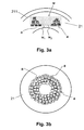
- FIG. 3a are illustrated by the depth setting of the focal point F different depth focal planes respectively Fokal lake defined which serve as processing planes respectively processing surfaces w, w 1 , w 2 , on which the eye tissue, such as the cornea 21, each in several separate, by scanning p defined processing sub-areas a is resolved.
- the Machining surfaces w, w 1 , w 2 by appropriately controlled depth adjustment of the focal point F or by the use in the light projector 11 of lenses with spherical image fields and curved (concave, convex) are designed, as shown in the Figure 3c is shown.
- 3b 11 illustrates, in plan view, an example of a plurality of non-contacting machining sub-areas a (eg, one hundred or more) juxtaposed and superimposed in an annular cluster to form a plurality of discrete, discontinuous cavities which collapse and thereby Change the corneal curvature for a desired refractive correction of the cornea 21 suitable.
- the control module 13 is set up to determine the currently achieved refractive correction of the cornea 21 based on the determined wavefront profile and, based thereon, to determine the local distribution of further processing subareas a or the starting points for corresponding scanning patterns p in order to achieve the desired refractive correction of the cornea 21 .
- the determination of the wavefront profile and the starting points for further processing subareas a is carried out at different times, for example periodically according to a predetermined time schedule, after the eye tissue has been resolved in all planned processing subareas a on a processing surface w, w 1 , w 2 , after Processing all planned processing subareas a and / or after receiving an input via a user interface instruction signal.
- the control module 13 is preferably implemented as a programmed logic module by means of software and / or hardware.
- the control module 13 is connected to the positioning module 16 and the scanning module 15 for transmitting control signals and / or control data.
- the control module 13 is connected to the wavefront detector 18 and / or the eye monitoring module 12 for receiving feedback or data values via eye movements.
- the control module 13 is arranged in a separate housing or in a housing common with the light projection module 11.
- the control module 13 is set up for a desired refractive correction of the eye 2, in particular the cornea 21, to determine the local distribution of the necessary processing subareas a inside the eye 2, that is, the number of processing subareas a, the respective assigned starting points (in a plurality of processing surfaces) and, in a variant, also the corresponding scanning pattern p or the size, shape and / or orientation of the machining subregions a defined by the scanning pattern p.
- the control module 13 is configured to determine the wavefront profile of a light beam reflected by the eye 2 and thus the current refractive power of the cornea 21 by means of the wavefront detector 18, and based on this, to determine the spatial distribution of the processing subregions a inside the eye 2.
- step S2 the control module 13 determines the local distribution of the processing subareas a to achieve the desired refractive correction.
- control module 13 transmits the starting points for the scanning patterns p of the machining subregions a to the positioning module 16, for example as a sequence of starting points, ordered according to decreasing depth of the machining surface w, w 1 , w 2 .
- identification elements of different sampling patterns p are also assigned to the different starting points.
- control values for different scanning patterns p are also transmitted to the scanning module 15.
- step S4 the treatment of the eye 2 is started by a start signal entered via the user interface.
- step S5 the focal point F is positioned on the lowest-lying working surface w 1 .
- the corresponding control of the depth positioning module 14 is preferably carried out by the control module 13.
- step S6 the positioning module 16 positions the focal point F in the current processing area w, w 1 , w 2 to an unused starting point.
- the positioning takes place according to specification of the starting point by the control module 13 or according to a previously stored in the positioning module 16 sequence of starting points. Positioning also involves constantly monitored eye movements taken into account and compensated either in the control module 13 or in the positioning module 16.
- the wavefront detector 18 determines the wavefront profile of the eye 2 and transmits it to the control module 13 (without steps S11, S12, S13, the method ends in step S14).
- step S12 the control module 13 determines whether the desired refractive correction has been achieved based on the wavefront profile. If the desired correction has been achieved, the control module 13 ends the process in step S14, for example with a success message via the user interface. Otherwise, if the desired refractive correction has not yet been reached, the control module continues in step S13.
Abstract
Description
Die vorliegende Erfindung betrifft eine ophthalmologische Vorrichtung für die refraktive Korrektur eines Auges. Die Erfindung betrifft insbesondere eine ophthalmologische Vorrichtung für die refraktive Korrektur eines Auges mittels Projektion von Laserpulsen auf einen Brennpunkt im Innern des Auges für eine Auflösung von Augengewebe.The present invention relates to an ophthalmic device for the refractive correction of an eye. In particular, the invention relates to an ophthalmological device for the refractive correction of an eye by means of projection of laser pulses on a focal point in the interior of the eye for a resolution of eye tissue.
Fehlsichtigkeiten wie Myopie (Kurzsichtigkeit), Hyperopie (Weitsichtigkeit oder Übersichtigkeit) oder Astigmatismus (Stabsichtigkeit) können heute durch refraktiv-chirurgische Behandlung dauerhaft korrigiert werden. Refraktiv-chirurgische Behandlungen sind chirurgische Eingriffe am Auge, die die optische Brechkraft des Auges ändern mit dem Ziel, diese einem gewünschten Wert möglichst gut anzunähern. Mittels Femtolasersystemen, die Pulsbreiten von typisch 10fs bis 1000fs (1fs=10-15s) aufweisen, können transparente Materialen im Fokus durch nichtlineare Absorption und anschliessende Wechselwirkung (z.B. Photodisruption) bearbeitet werden. Insbesondere werden in der Praxis in der Augenhornhaut (Cornea) durch Gewebeauflösung mittels Femtolaserpulsen operativ Schnitte erzeugt.Apertures such as myopia (myopia), hyperopia (farsightedness or clarity) or astigmatism (astigmatism) can be permanently corrected by refractive surgical treatment. Refractive surgical treatments are surgical procedures on the eye, which change the optical power of the eye with the aim of approximating it to a desired value as well as possible. By means of femtolaser systems, which have pulse widths of typically 10 fs to 1000 fs (1 fs = 10 -15 s), transparent materials in the focus can be processed by non-linear absorption and subsequent interaction (eg photodisruption). In particular, surgical incisions are produced in the cornea of the eye (cornea) by tissue resolution by means of femtolaser pulses.
In der Patentschrift
Im Artikel von
Es ist eine Aufgabe der vorliegenden Erfindung, eine neue ophthalmologische Vorrichtung für die refraktive Korrektur eines Auges mittels Laserpulsen vorzuschlagen, welche insbesondere nicht auf die Korrektur der Kurzsichtigkeit beschränkt sind.It is an object of the present invention to propose a new ophthalmic device for the refractive correction of an eye by means of laser pulses, which are in particular not limited to the correction of myopia.
Gemäss der vorliegenden Erfindung werden diese Ziele durch die Elemente des unabhängigen Anspruchs erreicht. Weitere vorteilhafte Ausführungsformen gehen ausserdem aus den abhängigen Ansprüchen und der Beschreibung hervor.According to the present invention, these objects are achieved by the elements of the independent claim. Further advantageous embodiments are also evident from the dependent claims and the description.
Die oben genannten Ziele werden durch die vorliegende Erfindung insbesondere dadurch erreicht, dass die ophthalmologische Vorrichtung, welche einen Lichtprojektor umfasst zur Projektion von Laserpulsen auf einen Brennpunkt im Innern des Auges zur Auflösung von Augengewebe, zudem ein Positionierungsmodul und ein Abtastmodul umfasst. Das Positionierungsmodul ist eingerichtet, den Brennpunkt an unterschiedliche Ausgangspunkte zu positionieren. Das Abtastmodul ist eingerichtet, den Brennpunkt ausgehend von jeweils einem der Ausgangspunkte gemäss einem Abtastmuster für ein Bearbeitungsteilgebiet zu bewegen, wobei das Abtastmuster und die Ausgangspunkte so definiert sind, dass das Augengewebe in mehreren durch Gewebebrücken voneinander getrennten Bearbeitungsteilgebieten aufgelöst wird. Das Abtastmuster definiert beispielsweise ein Bearbeitungsteilgebiet mit einer rechteckigen, runden, elliptischen, sternförmigen oder spiralförmigen Form oder in einer Form ähnlich einer Lissajou-Figur. Zum Ablenken der Laserpulse umfasst das Abtastmodul beispielsweise einen Galvanoscanner, einen resonanten Spiegelscanner, einen akustischen optischen Modulator, einen Polygonscanner und/oder einen mikroelektromechanischen Scanner. Das Positionierungsmodul umfasst Bewegungstreiber zum mechanischen Verschieben von mindestens Teilen des Lichtprojektors und/oder einen Galvanoscanner zum Ablenken der Laserpulse. Der Lichtprojektor weist vorzugsweise eine numerische Apertur von über 0.3 auf. Die ophthalmologische Vorrichtung umfasst beispielsweise ein Steuermodul, welches eingerichtet ist, das Positionierungsmodul und das Abtastmodul so zu steuern, dass das Positionierungsmodul den Brennpunkt so an unterschiedliche Ausgangspunkte positioniert und dass das Abtastmodul den Brennpunkt ausgehend von jeweils einem der Ausgangspunkte gemäss dem Abtastmuster so bewegt, dass das Augengewebe in mehreren durch Gewebebrücken voneinander getrennten Bearbeitungsteilgebieten aufgelöst wird. Durch die Bildung einer Vielzahl von getrennten, nicht zusammenhängenden Bearbeitungsteilgebieten mit aufgelöstem Augengewebe ist es möglich die Krümmung der Augenhornhaut nicht bloss wie im Stand der Technik zentralsymmetrisch zur Korrektur einer Myopie abzuflachen, sondern für eine refraktive Korrektur die Krümmung der Augenhornhaut an beinahe beliebigen Stellen und insbesondere auch asymmetrisch zu ändern. Beispielsweise können, durch geeignete Wahl der Ausgangspunkte, mehrere der Bearbeitungsteilgebiete in einem ringförmigen Cluster im (intrastromalen) Hornhautgewebe so angeordnet werden, dass eine Hyperopie korrigiert werden kann. Durch unterschiedliche Verteilung der Bearbeitungsteilgebiete in der Hornhaut, sowohl in der Tiefe als auch in der Distanz zur optischen Achse des Auges, und/oder durch mehrschichtige Anordnung der Bearbeitungsteilgebiete im Hornhautgewebe kann die Hornhautkrümmung zur Korrektur von Astigmatismus und Aberrationen höherer Ordnung geeignet verändert werden. Neben der Behandlung und Korrektur der Augenhornhaut ist es zudem auch möglich, durch die ophthalmologische Vorrichtung auf die gleiche Art das Gewebe der Augenlinse zu behandeln, insbesondere zur Verbesserung der Elastizität der Linse bei Altersweitsichtigkeit.The above-mentioned objects are achieved by the present invention in particular by the fact that the ophthalmological device, which comprises a light projector for projecting laser pulses onto a focal point inside the eye for dissolving eye tissue, additionally comprises a positioning module and a scanning module. The positioning module is set up to position the focal point at different starting points. The scanning module is arranged to move the focal point from each one of the starting points according to a scanning pattern for a machining sub-area, wherein the scanning pattern and the starting points are defined so that the eye tissue is dissolved in a plurality of processing sections separated by tissue bridges. The scanning pattern defines, for example, a machining subregion having a rectangular, round, elliptical, star-shaped or spiral shape or in a shape similar to a Lissajou figure. For deflecting the laser pulses, the scanning module comprises, for example, a galvanoscanner, a resonant mirror scanner, an acoustic optical modulator, a polygon scanner and / or a microelectromechanical scanner. The positioning module includes motion drivers for mechanically displacing at least portions of the light projector and / or a galvano scanner for deflecting the laser pulses. The light projector preferably has a numerical aperture of more than 0.3. The ophthalmic device includes, for example, a control module configured to control the positioning module and the scanning module such that the positioning module positions the focal point at different starting points and that the scanning module moves the focal point from one of the starting points according to the scanning pattern the ocular tissue is dissolved in a plurality of processing sections separated by tissue bridges. The formation of a plurality of separate, non-contiguous, eyelet-processed portions of the eye cornea not only allows the curvature of the cornea to be centrally symmetric, as in the prior art, to correct a corneal injury To flatten myopia, but for a refractive correction to change the curvature of the cornea at almost any point and in particular asymmetrically. For example, by appropriate choice of the starting points, several of the processing subregions may be arranged in an annular cluster in the (intrastromal) corneal tissue such that hyperopia can be corrected. By different distribution of the processing subregions in the cornea, both in the depth and in the distance to the optical axis of the eye, and / or by multilayer arrangement of the processing subregions in the corneal tissue, the corneal curvature can be suitably changed to correct astigmatism and higher order aberrations. In addition to the treatment and correction of the cornea, it is also possible to treat by the ophthalmic device in the same way the tissue of the eye lens, in particular to improve the elasticity of the lens in case of presbyopia.
In einer bevorzugten Ausführungsvariante ist das Positionierungsmodul eingerichtet, den Brennpunkt jeweils an Ausgangspunkte auf einer ersten Bearbeitungsfläche zu positionieren, und das Abtastmodul ist eingerichtet, den Brennpunkt in dieser ersten Bearbeitungsfläche zu bewegen. Die ophthalmologische Vorrichtung umfasst zudem ein Tiefenpositionierungsmodul zum Verschieben des Brennpunkts entlang einer Projektionsachse des Lichtprojektors in eine zur ersten Bearbeitungsfläche äquidistante, z.B. parallele, zweite Bearbeitungsfläche, so dass der Brennpunkt in der zweiten Bearbeitungsfläche an unterschiedliche Ausgangspunkte positionierbar und ausgehend von jeweils einem der Ausgangspunkte gemäss dem Abtastmuster bewegbar ist. Durch die Tiefenpositionierung des Brennpunkts können mehrere Fokalflächen, z.B. Fokalebenen, eingestellt werden, welche jeweils eine Bearbeitungsfläche, z.B. Bearbeitungsebene, bilden, auf der die Ausgangspunkte jeweils definiert und das Augengewebe in Bearbeitungsteilgebieten aufgelöst wird. Die Tiefenpositionierung des Brennpunkts ermöglicht somit eine mehrschichtige Bearbeitung des Augengewebes mit jeweils einer Vielzahl von getrennten, nicht zusammenhängenden Bearbeitungsteilgebieten, in denen das Augengewebe aufgelöst wird. Vorzugsweise wird dabei die Distanz zwischen einzelnen Fokalflächen respektive Bearbeitungsflächen so bestimmt, dass bei übereinander liegenden Bearbeitungsteilgebieten benachbarter Bearbeitungsflächen, jeweils eine Gewebebrücke bestehen bleibt. Zu diesem Zweck ist das Steuermodul zudem vorzugsweise eingerichtet, das Tiefenpositionierungsmodul so zu steuern, dass beim Verschieben des Brennpunkts eine Mindestdistanz zwischen den Bearbeitungsflächen eingehalten wird, wobei die Mindestdistanz so definiert ist, dass in äquidistanten (parallelen) Bearbeitungsflächen über einander liegende Bearbeitungsteilgebiete durch Gewebebrücken voneinander getrennt sind. Der Zweck und Vorteil der Gewebebrücken besteht darin, dass definierte Abtragschichtdicken erzeugt werden können. Es hat sich nämlich herausgestellt, dass bei der Laserbearbeitung entstehende innere Gasdrucke eine Deformation des Gewebes erzeugen, die die Präzision beim schichtweisen Abtragen von grossen zusammenhängenden Schichten, wie es im Stand der Technik beschrieben wird, stark beeinträchtigt.In a preferred embodiment variant, the positioning module is set up to position the focal point in each case at starting points on a first processing surface, and the scanning module is set up to move the focal point in this first processing surface. The ophthalmological apparatus further comprises a depth positioning module for shifting the focal point along a projection axis of the light projector into a second, eg parallel, second processing surface equidistant from the first processing surface, so that the focal point in the second processing surface can be positioned at different starting points and from each one of the starting points according to FIG Scanning pattern is movable. Due to the depth positioning of the focal point, a plurality of focal surfaces, eg focal planes, can be adjusted, each of which forms a processing surface, eg processing plane, on which the starting points are respectively defined and the eye tissue is resolved in processing subregions. The depth positioning of the Focal point thus allows a multi-layer processing of the eye tissue, each with a plurality of separate, non-contiguous processing subdomains in which the eye tissue is dissolved. In this case, the distance between individual focal surfaces or processing surfaces is preferably determined such that in the case of superimposed processing subregions of adjacent processing surfaces, in each case one tissue bridge remains. For this purpose, the control module is also preferably arranged to control the depth positioning module so that when moving the focal point a minimum distance between the processing surfaces is maintained, the minimum distance is defined so that in equidistant (parallel) processing surfaces overlying processing subregions by fabric bridges from each other are separated. The purpose and advantage of the fabric bridges is that defined Abtragschichtdicken can be generated. It has been found that internal gas pressures generated during laser processing produce a deformation of the tissue which severely impairs the precision in the stratified removal of large contiguous layers, as described in the prior art.
In einer Ausführungsvariante ist das Steuermodul eingerichtet, entsprechend einer gewünschten refraktiven Korrektur des Auges, die Anzahl der Bearbeitungsteilgebiete sowie die Ausgangspunkte für die örtliche Verteilung der Bearbeitungsteilgebiete in mehreren Bearbeitungsflächen im Innern des Auges zu bestimmen. Das Steuermodul bestimmt die örtliche Verteilung der Bearbeitungsteilgebiete beispielsweise auf Grund eines Modells des zu behandelnden Augengewebes, z.B. ein Hornhautmodel, bei vorgegebener Grösse und Form der Bearbeitungsteilgebiete und bei vorgegebenen vertikalen und horizontalen Mindestabständen einzelner Bearbeitungsteilgebiete.In one embodiment variant, the control module is set up in accordance with a desired refractive correction of the eye to determine the number of processing subregions and the starting points for the local distribution of the processing subregions in a plurality of processing surfaces in the interior of the eye. The control module determines the local distribution of the processing subregions, for example based on a model of the eye tissue to be treated, eg a cornea model, given size and shape of the processing subdomains and given vertical and horizontal minimum distances of individual processing subdomains.
In einer Ausführungsvariante ist das Steuermodul zudem eingerichtet, unterschiedliche Abtastmuster für unterschiedlich grosse Bearbeitungsteilgebiete zu wählen.In one embodiment variant, the control module is also set up to select different scanning patterns for processing areas of different sizes.
In einer bevorzugten Ausführungsvariante umfasst die Vorrichtung einen Wellenfrontdetektor zum Bestimmen eines Wellenfrontverlaufs eines durch das Auge reflektierten Lichtbündels. Das Steuermodul ist zudem eingerichtet, die Ausgangspunkte basierend auf dem bestimmten Wellenfrontverlauf festzulegen. Das heisst, das Steuermodul ist eingerichtet, die örtliche Verteilung der Bearbeitungsteilgebiete basierend auf dem bestimmten Wellenfrontverlauf festzulegen. Dadurch kann die erreichte refraktive Korrektur während der Behandlung gemessen werden und, darauf basierend, die Positionierung weiterer Bearbeitungsteilgebiete, so weit nötig, bestimmt werden.In a preferred embodiment, the device comprises a wavefront detector for determining a wavefront profile of a light beam reflected by the eye. The control module is further configured to set the starting points based on the particular wavefront history. That is, the control module is configured to determine the local distribution of the processing subregions based on the determined wavefront history. As a result, the refractive correction achieved during the treatment can be measured and, based on this, the positioning of further processing subregions, if necessary, can be determined.
Vorzugsweise ist das Abtastmodul eingerichtet, nacheinander folgende Laserpulse so zu positionieren, dass sich ihre Fokusdurchmesser teilweise überlappen. Vorzugsweise überlappen sich ihre Fokusdurchmesser mindestens bis zur Hälfte ihres Durchmessers. Durch die Überlappung der Fokusdurchmesser können Laserpulse mit geringere Pulsenergie für die Gewebeauflösung eingesetzt werden, wodurch nur geringe mechanische Spannungen durch Gas und Kavitationsblasen im Restgewebe induziert werden, was bei der Bildung von gleichmässig dünnen Abtragsbereichen hilft und einer definierten Kollabierung der Bearbeitungsteilgebiete förderlich ist. Insbesondere zusammen mit der Verwendung hoher numerischer Aperturen, beispielsweise >0.3, insbesondere >0.4, und der damit verbundenen geringeren erforderlichen Pulsenergien, lassen sich sehr regelmässige Abtragsvolumina mit geringer Höhe und geringem Aspektverhältnis erzeugen (Annäherung an Sphäre). Es ist sogar möglich mit hoher numerischer Apertur und Pulsen von sehr kurzer Dauer und geringer Energie gasarme oder sogar gasfreie Schnitte zu erzeugen. Überhitzungen, wie im Stand der Technik erwähnt, treten dabei selbst bei grossen Überlappungen einzelner Laserpulse nicht auf.The scanning module is preferably set up to successively position the following laser pulses such that their focal diameters partially overlap. Preferably, their focus diameter overlap at least to half their diameter. By overlapping the focus diameter laser pulses can be used with less pulse energy for tissue resolution, whereby only small mechanical stresses induced by gas and cavitation bubbles in the residual tissue, which helps in the formation of uniformly thin Abtragsbereiche and a defined collapse of the processing subregions is conducive. In particular, together with the use of high numerical apertures, for example,> 0.3, in particular> 0.4, and the associated lower required pulse energies, very regular Abtragsvolumina can generate low height and low aspect ratio (approach to sphere). It is even possible with high numerical aperture and pulses of very short duration and low energy to produce gas-poor or even gas-free cuts. Overheating, as mentioned in the prior art, does not occur even with large overlaps of individual laser pulses.
Vorzugsweise ist das Abtastmodul eingerichtet, den Brennpunkt wesentlich schneller zu bewegen als die Bewegungsgeschwindigkeit eines menschlichen Auges bei einer Blickrichtungsänderung. Wenn das Auge während der Behandlung nicht mechanisch fixiert wird und sich bewegt, dann kann zwar die Grösse des durch das Abtastmuster definierten Bearbeitungsteilgebiets durch die Augenbewegung leicht verändert werden, doch das Abtastmodul bewegt den Brennpunkt schnell genug, um zu verhindern, dass im Bearbeitungsteilgebiet auf Grund der Augenbewegungen Gewebebrücken verbleiben. Zudem umfasst die Vorrichtung ein Augenüberwachungsmodul zur Bestimmung von Augenbewegungen, und ist eingerichtet, das Positionierungsmodul basierend auf den bestimmten Augenbewegungen für einen entsprechenden Positionierungsausgleich anzusteuern. Da das Positionierungsmodul den Brennpunkt mit einer wesentlich kleineren Frequenz positioniert als das Abtastmodul, wirken sich Augenbewegungen auch entsprechend stärker auf die Positionierung des Brennpunkts an die Ausgangspunkte aus. Durch die Bestimmung der Augenbewegungen, z.B. auf der Basis von Iris- oder Venenmuster (auf der Sclera oder er Retina), kann der Einfluss der Augenbewegung jeweils bei der Positionierung des Brennpunkts an einen neuen Ausgangspunkt kompensiert werden. Die hohe Ablenkungsgeschwindigkeit des Abtastmoduls für die Erzeugung von Hohlräumen entsprechend dem Abtastmuster und die Kompensation von Augenbewegungen bei der Positionierung der Ausgangspunkte ermöglichen die refraktive Korrektur des Auges, ohne das Auge dafür am Lichtprojektor fixieren zu müssen. Durch die hohe Anzahl der Bearbeitungsteilgebiete, beispielsweise hundert, mitteln sich Bewegungsartefakte aus dem Abtragergebnis heraus. Die Erzeugung der Vielzahl von getrennten Hohlräumen mit hoher Ablenkungsgeschwindigkeit und die Kompensation der Augenbewegungen bei der Positionierung der Hohlräume ermöglichen somit die refraktive Korrektur des Auges mittels Laserpulsen, ohne dass das Auge und/oder der Patient in irgend einer Form mechanisch mit dem Lasersystem verbunden oder fixiert werden müssen.Preferably, the scanning module is arranged to move the focal point much faster than the speed of movement of a human eye in a viewing direction change. While the eye does not mechanically fix and move during the treatment, while the size of the machining sub-area defined by the scanning pattern can be easily changed by eye movement, the scanning module moves the focus fast enough to prevent the machining sub-area from being affected the eye movements remain tissue bridges. In addition, the device comprises an eye monitoring module for determining eye movements, and is set up to control the positioning module based on the determined eye movements for a corresponding positioning compensation. Since the positioning module positions the focal point at a much lower frequency than the scanning module, eye movements also have a correspondingly greater effect on the positioning of the focal point at the starting points. By determining the eye movements, eg on the basis of iris or venous patterns (on the sclera or retina), the influence of eye movement can be compensated for each time the focus is positioned at a new starting point. The high deflection speed of the scanning module for the generation of cavities according to the scanning pattern and the compensation of eye movements in the positioning of the starting points allow the refractive correction of the eye, without having to fix the eye on the light projector. Due to the high number of processing subareas, for example one hundred, motion artifacts average out of the result of the removal. The generation of the plurality of separate cavities with high deflection speed and the compensation of eye movements in the positioning of the cavities thus allow the refractive correction of the eye by means of laser pulses, without the eye and / or the patient mechanically connected or fixed in any form with the laser system Need to become.
Vorzugsweise definiert das Abtastmuster ein Bearbeitungsteilgebiet, dessen Durchmesser kleiner als die Dicke der Hornhaut ist. Wenn die Ausmasse des Bearbeitungsteilgebiets mit aufgelöstem Augengewebe kleiner sind, als die Dicke der Hornhaut, dann ist der an der Hornhautoberfläche ersichtliche Dickenverlust kleiner, als es der Höhe des aufgelösten Augengewebes entsprechen würde, insbesondere, wenn das Bearbeitungsteilgebiet mit dem aufgelösten Augengewebe von der Hornhautoberfläche entfernt ist (beispielsweise mehr als die Hälfte eines Fokusdurchmessers). Über die seitliche Ausdehnung (Durchmesser) und die Tiefenpositionierung eines Bearbeitungsteilgebiets kann dieser Effekt (der beschränkten Dickenreduktion an der Hornhautoberfläche) beeinflusst werden. Somit können durch Bearbeitungsteilgebiete, deren Durchmesser kleiner als die Dicke der Hornhaut ist, Brechkraftänderungen erzielt werden, die kleiner sind, als die der aufgelösten Gewebehöhe entsprechende Brechkraftänderung. Gemäss einer Faustformel für LASIK (Laser In Situ Keratomileusis) entspricht beispielsweise ein Hornhautabtrag von 12µm ungefähr einer Dioptrie. Durch die Auflösung von Augengewebe in kleinen, von der Hornhautoberfläche entfernten Bearbeitungsteilgebieten können somit Korrekturen der Brechkraft vorgenommen werden, die feiner sind, als dies durch eine ausgedehnte Gewebeauflösung der selben Höhe mittels den selben Laserpulsen möglich wäre.Preferably, the scanning pattern defines a processing subregion whose diameter is smaller than the thickness of the cornea. If the dimensions of the processing part area with dissolved ocular tissue are smaller than the thickness of the cornea, then the apparent thickness loss at the corneal surface is smaller than the height of the dissolved ocular tissue, especially if the processing part area with the dissolved ocular tissue is away from the corneal surface is (for example, more than half of a focus diameter). The lateral extent (diameter) and the depth positioning of a machining part area can influence this effect (the limited thickness reduction at the corneal surface). Thus, by processing subregions whose diameter is smaller than the thickness of the cornea, refractive power changes can be achieved that are smaller than the refractive power change corresponding to the dissolved tissue height. According to a rule of thumb for LASIK (Laser In Situ Keratomileusis), for example, a corneal ablation of 12 μm corresponds to approximately one diopter. Thus, by the resolution of ocular tissue in small parts of the cornea away from the corneal surface, corrections of the refractive power can be made that are finer than would be possible by an extensive tissue resolution of the same height by means of the same laser pulses.
Nachfolgend wird eine Ausführung der vorliegenden Erfindung anhand eines Beispieles beschrieben. Das Beispiel der Ausführung wird durch die folgenden beigelegten Figuren illustriert:
-
Figur 1 a zeigt ein Blockdiagramm, welches schematisch eine ophthalmologische Vorrichtung bei der Behandlung eines Auges mittels eines fokussierten gepulsten Laserstrahls darstellt. -
Figur 1b zeigt eine Aufsicht einer durch die ophthalmologische Vorrichtung gemäss einem Abtastmuster bearbeiteten Bearbeitungsfläche. -
Figur 2 -
Figur 3a zeigt einen Querschnitt durch ein Segment einer Augenhornhaut, in welcher zur refraktiven Korrektur Augengewebe in einer Vielzahl von voneinander getrennten Bearbeitungsteilgebieten aufgelöst wird. -
Figur 3b zeigt eine Aufsicht einer Augenhornhaut, in welcher Gewebe zur refraktiven Korrektur in einer Vielzahl von sich nicht berührenden, in einem ringförmigen Cluster nebeneinander und übereinander liegend angeordneten Bearbeitungsteilgebieten aufgelöst wird. -
Figur 3c zeigt einen weiteren Querschnitt durch das Segment der Augenhornhaut, in welcher die von voneinander getrennten Bearbeitungsteilgebiete in äquidistanten, gekrümmten Bearbeitungsflächen angeordnet sind. -
Figur 4 zeigt in der Aufsicht die Überlappung der Fokusdurchmesser von mehreren nacheinander folgenden Laserpulsen.
-
FIG. 1 Fig. a shows a block diagram which schematically illustrates an ophthalmic device in the treatment of an eye by means of a focused pulsed laser beam. -
FIG. 1b shows a plan view of a processed by the ophthalmic device according to a scanning pattern processing surface. -
FIG. 2 FIG. 12 is a flow chart illustrating the process of refractive correction of ocular tissue by the tissue resolution in a plurality of separate processing regions. FIG. -
FIG. 3a shows a cross-section through a segment of a cornea, in which for refractive correction eye tissue is dissolved in a plurality of separate processing subregions. -
FIG. 3b shows a plan view of a cornea, in which refractive correction tissue in a plurality of non-contacting, in an annular cluster adjacent to each other and superimposed processing sub-areas is resolved. -
Figure 3c shows a further cross section through the segment of the cornea, in which the mutually separate processing subregions are arranged in equidistant, curved processing surfaces. -
FIG. 4 shows in the plan view the overlap of the focus diameter of several successive laser pulses.
In der
Zum besseren Verständnis soll hier angeführt werden, dass die
Wie in der
Das Positionierungsmodul 16 ist eingerichtet, den Brennpunkt F an definierte Ausgangspunkte zu positionieren. Das Positionierungsmodul 16 umfasst beispielsweise Bewegungstreiber zum mechanischen Verschieben des Lichtprojektors 11 oder von Teilen des Lichtprojektors 11, zum Beispiel Bewegungstreiber für die laterale Verschiebung von Linsen. Die Bewegungstreiber umfassen beispielsweise ein Antriebselement für eine Vorschubrichtung x und ein Antriebselement für eine zur Vorschubrichtung x senkrechte Abtastrichtung y (siehe
Das Abtastmodul 15 ist eingerichtet, den Brennpunkt F ausgehend vom aktuellen Ausgangspunkt gemäss einem definierten Abtastmuster p zu bewegen (siehe
Eine ophthalmologische Vorrichtung mit einer mechanischen Bewegung des Lichtprojektors und einer Überlagerung einer zusätzlichen feinen Bewegung des Brennpunkts F mittels optischer Microscans wird in der per Referenz miteingeschlossenen
Wie in der
In einer weiteren Ausführungsvariante umfasst die ophthalmologische Vorrichtung 1 einen Wellenfrontdetektor 18 zum Bestimmen eines Wellenfrontverlaufs eines durch das Auge 2 reflektierten Lichtbündels. Das reflektierte Lichtbündel ist ein zusätzlicher Referenzlichtstrahl, der vom Augenhintergrund reflektiert und dem Wellenfrontdetektor 18 mittels optischer Elemente zugeführt wird. Der Wellenfrontdetektor ist beispielsweise als Shack-Hartmann-Sensor ausgeführt, beispielsweise nach
In einer weiteren Ausführungsvariante umfasst die ophthalmologische Vorrichtung 1 ein Augenüberwachungsmodul 12 (ein so genannter "Eye Tracker") zur Bestimmung von Augenbewegungen. Das Augenüberwachungsmodul 12 umfasst beispielsweise eine Kamera, beispielsweise eine CCD-Kamera (Charged Coupled Device) und eine Beleuchtungseinrichtung (z.B. LEDs), zur Erfassung einer Aufsicht des Auges 2, sowie Verarbeitungsmittel zur Bestimmung des Iris- oder Venenmusters (auf der Sclera oder der Retina) in der Aufsicht und zur Bestimmung von Augenbewegungen basierend auf relativen Verschiebungen des Iris- oder Venenmusters. Die Verarbeitungsmittel sind als programmiertes Logikmodul mittels Software und/oder Hardware ausgeführt und sind in einer Variante im Steuermodul 13 angeordnet. Detektierte Augenbewegungen werden vom Augenüberwachungsmodul 12 laufend an das Positionierungsmodul 16 oder an das Steuermodul 13 übertragen, beispielsweise als Relativwerte bezüglich einer definierten Referenzposition des Auges 2 oder als Blickrichtungswerte des Auges 2. Das Positionierungsmodul 16 respektive das Steuermodul 13 ist eingerichtet, bei der Positionierung des Brennpunkts F in einen Ausgangspunkt Bewegungen des Auges 2 basierend auf den bestimmten Augenbewegungen auszugleichen. Das Positionierungsmodul 16 korrigiert die Koordinaten vorgegebener Ausgangspunkte basierend auf den detektierten Augenbewegungen oder das Steuermodul 13 liefert dem Positionierungsmodul 16 Ausgangspunkte, deren Koordinaten entsprechend den Augenbewegungen angepasst sind.In a further embodiment, the
Das Steuermodul 13 ist vorzugsweise als programmiertes Logikmodul mittels Software und/oder Hardware ausgeführt. Das Steuermodul 13 ist zur Übertragung von Steuersignalen und/oder Steuerdaten mit dem Positionierungsmodul 16 und dem Abtastmodul 15 verbunden. Je nach Ausführungsvariante ist das Steuermodul 13 zum Empfang von Rückmeldungen oder Datenwerten über Augenbewegungen mit dem Wellenfrontdetektor 18 und/oder dem Augenüberwachungsmodul 12 verbunden. Das Steuermodul 13 ist in einem separaten oder in einem mit dem Lichtprojektionsmodul 11 gemeinsamen Gehäuse angeordnet. Das Steuermodul 13 ist eingerichtet, für eine gewünschte refraktive Korrektur des Auges 2, insbesondere der Augenhornhaut 21, die örtliche Verteilung der dazu nötigen Bearbeitungsteilgebiete a im Innern des Auges 2 zu bestimmen, das heisst die Anzahl der Bearbeitungsteilgebiete a, die jeweils zugeordneten Ausgangspunkte (in mehreren Bearbeitungsflächen) und in einer Variante auch das entsprechende Abtastmuster p respektive die durch das Abtastmuster p definierte Grösse, Form und/oder Ausrichtung der Bearbeitungsteilgebiete a. In einer Variante ist das Steuermodul 13 eingerichtet, den Wellenfrontverlauf eines durch das Auge 2 reflektierten Lichtbündels und damit die aktuelle Brechkraft der Augenhornhaut 21 mittels des Wellenfrontdetektors 18 zu ermitteln, und darauf basierend die örtliche Verteilung der Bearbeitungsteilgebiete a im Innern des Auges 2 zu bestimmen.The
Das Steuermodul 13 bestimmt die Anzahl und örtliche Verteilung der Bearbeitungsteilgebiete a beispielsweise auf Grund einer Tabelle. Die Tabelle ordnet verschiedenen refraktiven Korrekturwerten (und Korrekturarten) jeweils eine Anzahl und örtliche Verteilung der Bearbeitungsteilgebiete a zu. In einer weiteren Variante bestimmt das Steuermodul 13 die Anzahl und örtliche Verteilung der Bearbeitungsteilgebiete a auf Grund eines Modells des zu behandelnden Augengewebes, z.B. ein Augenhornhautmodel und Informationen darüber, wie das Auge 2 abbildet, bei vorgegebener Grösse und Form der Bearbeitungsteilgebiete a und bei vorgegebenen vertikalen und horizontalen Mindestabständen einzelner Bearbeitungsteilgebiete a. Die Angaben über die Anzahl und die örtliche Verteilung der Bearbeitungsteilgebiete a können auch von einer externen Einheit an das Steuermodul 13 übermittelt werden. Die örtliche Verteilung der Bearbeitungsteilgebiete a erfolgt so, dass die bei der Auflösung des Augengewebes in den Bearbeitungsteilgebieten a entstehenden Hohlräume sowohl auf der selben Bearbeitungsfläche w, w1, w2 als auch in benachbarten, übereinander liegenden Bearbeitungsflächen w1, w2 jeweils durch Gewebebrücken voneinander getrennt sind. Die Anzahl der Bearbeitungsteilgebiete a kann in einer Variante auch aus einem Abtragsvolumen bestimmt werden, dass für eine spezifizierte refraktive Korrektur bestimmt oder durch den Benutzer eingegeben wird. Die örtliche Anordnung der Bearbeitungsteilgebiete a wird durch die Korrekturart bestimmt, beispielsweise muss bei einer Myopie die Augenhornhaut 21 durch zentralisierte Abtragung abgeflacht werden, wohingegen bei einer Hyperopie die Krümmung der Hornhautoberfläche durch ringförmig umlaufende Abtragung steiler ausgestaltet werden muss.The
In den nachfolgenden Abschnitten wird mit Bezug zu der
Im Schritt S1 bestimmt das Steuermodul 13 die gewünschte refraktive Korrektur des Auges 2. Der Sollwert der refraktiven Korrektur wird beispielsweise über eine Benutzerschnittstelle eingegeben und im Steuermodul 13 erfasst.In step S1, the
Im Schritt S2 bestimmt das Steuermodul 13 die örtliche Verteilung der Bearbeitungsteilgebiete a, um die gewünschte refraktive Korrektur zu erreichen.In step S2, the
Im optionalen Schritt S3 übermittelt das Steuermodul 13 die Ausgangspunkte für die Abtastmuster p der Bearbeitungsteilgebiete a an das Positionierungsmodul 16 beispielsweise als Sequenz von Ausgangspunkten, geordnet nach abnehmender Tiefe der Bearbeitungsfläche w, w1, w2. In einer Variante sind den verschiedenen Ausgangspunkten auch Identifizierungselemente von unterschiedlichen Abtastmustern p zugeordnet. Gegebenenfalls werden auch Steuerwerte für unterschiedliche Abtastmuster p an das Abtastmodul 15 übermittelt.In the optional step S3, the
Im Schritt S4 wird die Behandlung des Auges 2 durch ein über die Benutzerschnittstelle eingegebenes Startsignal gestartet.In step S4, the treatment of the
Im Schritt S5 wird der Brennpunkt F auf die tiefstgelegene Bearbeitungsfläche w1 positioniert. Die entsprechende Ansteuerung des Tiefenpositionierungsmoduls 14 erfolgt vorzugsweise durch das Steuermodul 13.In step S5, the focal point F is positioned on the lowest-lying working surface w 1 . The corresponding control of the
Im Schritt S6 positioniert das Positionierungsmodul 16 den Brennpunkt F in der aktuellen Bearbeitungsfläche w, w1, w2 an einen noch nicht verwendeten Ausgangspunkt. Die Positionierung erfolgt gemäss Vorgabe des Ausgangspunkt durch das Steuermodul 13 oder gemäss einer vorher im Positionierungsmodul 16 gespeicherten Sequenz von Ausgangspunkten. Bei der Positionierung werden auch die dauernd überwachten Augenbewegungen berücksichtigt und entweder im Steuermodul 13 oder im Positionierungsmodul 16 kompensiert.In step S6, the
Im Schritt S7 bewegt das Abtastmodul 15 den Brennpunkt F in der aktuellen Bearbeitungsfläche w, w1, w2, ausgehend vom aktuellen Ausgangspunkt entsprechend dem Abtastmuster p, das dem aktuellen Ausgangspunkt zugeordnet ist. Das zu verwendende Abtastmuster p ist beispielsweise für die gesamte Behandlung unverändert oder wird durch das Steuermodul 13 oder das Positionierungsmodul 16, beispielsweise bei der Übermittlung eines Synchronisationssignals, mittels eines Identifizierungselements bestimmt.In step S7, the
Im Schritt S8 überprüft das Steuermodul 13, ob sämtliche Ausgangspunkte der aktuellen Bearbeitungsfläche w, w1, w2 bereits bearbeitet wurden. Falls zu bearbeitende Ausgangspunkte verbleiben, erfolgt die Positionierung des nächsten Ausgangspunkt im Schritt S6. Falls auf der aktuellen Bearbeitungsfläche w, w1, w2 alle zugeordneten Ausgangspunkte bearbeitet wurden, fährt das Steuermodul im Schritt S9 fort.In step S8, the
Im Schritt S9 überprüft das Steuermodul 13, ob sämtliche Bearbeitungsflächen w, w1, w2 bereits bearbeitet wurden. Falls zu bearbeitende Bearbeitungsflächen w, w1, w2 verbleiben, wird der Brennpunkt F im Schritt S10 auf die nächst höher gelegene, äquidistante (z.B. parallele) Bearbeitungsfläche w, w2 positioniert, auf der Ausgangspunkte zu bearbeiten sind, und das Positionierungsmodul 16 fährt im Schritt S6 mit der Positionierung des nächsten Ausgangspunkts fort. Ansonsten, wenn sämtliche Bearbeitungsflächen w, w1, w2 mit zu bearbeitenden Ausgangspunkten bereits bearbeitet wurden, fährt das Steuermodul im Schritt S11 fort.In step S9, the
Im optionalen Schritt S11 bestimmt der Wellenfrontdetektor 18 den Wellenfrontverlauf des Auges 2 und übermittelt diesen an das Steuermodul 13 (ohne Schritte S11, S12, S13 endet das Verfahren im Schritt S14).In the optional step S11, the
Im Schritt S12 bestimmt das Steuermodul 13 auf Grund des Wellenfrontverlaufs, ob die gewünschte refraktive Korrektur erreicht wurde. Falls die gewünschte Korrektur erreicht wurde, beendet das Steuermodul 13 das Verfahren im Schritt S14, beispielsweise mit einer Erfolgsmeldung über die Benutzerschnittstelle. Andernfalls, wenn die gewünschte refraktive Korrektur noch nicht erreicht wurde, fährt das Steuermodul im Schritt S13 fort.In step S12, the
Im Schritt S13 bestimmt das Steuermodul 13, vorzugsweise nach erfolgter Rückmeldung und Bestätigung über die Benutzerschnittstelle, die örtliche Verteilung zusätzlicher Bearbeitungsteilgebiete a, die zum Erreichen der gewünschten refraktiven Korrektur zu bearbeiten sind. Die Bearbeitung der weiteren Bearbeitungsteilgebiete a erfolgt im Schritt S5, gegebenenfalls nach der Übermittlung der zusätzlichen Ausgangspunkte an das Positionierungsmodul 16.In step S13, the
Claims (12)
- Ophthalmological device (1) for refractive correction of an eye (2), comprising:a laser source (17),a light projector (11) for projecting laser pulses (L') on a focus (F) in the interior of the eye (2) for breaking up eye tissue, anda positioning module (16) and a scanning module (15), which are arranged between laser source (17) and outlet of the light projector (11) as cascaded scanner modules for deflecting the laser pulses (L') in the beam path (L), the scanning module (15) being designed to move the focus (F) substantially faster than a movement speed of a human eye (2) when changing the direction of view, characterizedin that the positioning module (16) is a substantially slower scanner module than the scanning module (15) and comprises a galvano scanner, arranged in the beam path (L) downstream of the scanning module (15), for deflecting the laser pulses (L') in an advance direction (x) and in a scanning direction (y) perpendicular to the advance direction (x).
- Device (1) according to Claim 1, characterized in that the device (1) comprises an eye monitoring module (12) for determining eye movements.
- Device (1) according to Claim 2, characterized in that the positioning module (16) is designed to position the focus (F) at different initial points in the interior of the cornea (21) and, in the process, compensate for movements of the eye (2) on the basis of the determined eye movements.
- Device (1) according to Claim 3, characterized in that the scanning module (15) is designed to move the focus (F) from respectively one of the initial points as per a scanning pattern (p) in order to treat a treatment subsection (a) in the interior of the cornea (21), respectively using a plurality of laser pulses (L').
- Device (1) according to one of Claims 1 to 4, characterized in that the scanning module (15) for deflecting the laser pulses (L') comprises a galvano scanner.
- Device (1) according to one of Claims 1 to 5, characterized in that the scanning module (15) for deflecting the laser pulses (L') comprises a resonant mirror scanner.
- Device (1) according to one of Claims 1 to 6, characterized in that the scanning module (15) for deflecting the laser pulses (L') comprises an acousto-optic modulator.
- Device (1) according to one of Claims 1 to 7, characterized in that the scanning module (15) for deflecting the laser pulses (L') comprises a polygon scanner.
- Device (1) according to one of Claims 1 to 8, characterized in that the scanning module (15) for deflecting the laser pulses (L') comprises a microelectromechanical scanner.
- Device (1) according to one of Claims 1 to 9, characterized in that the scanning module (15) is designed to position successive laser pulses (L') such that the focal diameters (P1, P2) thereof partly overlap.
- Device (1) according to Claim 10, characterized in that their focal diameters (P1, P2) at least overlap up to half of the diameter thereof.
- Device (1) according to one of Claims 1 to 11, characterized by a depth positioning module (14) for displacing the focus (F) along a projection axis (z) of the light projector (11).
Priority Applications (1)
| Application Number | Priority Date | Filing Date | Title |
|---|---|---|---|
| EP10009126A EP2298256B1 (en) | 2006-09-07 | 2006-09-07 | Ophthalmological device for the refractive correction of an eye |
Applications Claiming Priority (2)
| Application Number | Priority Date | Filing Date | Title |
|---|---|---|---|
| EP10009126A EP2298256B1 (en) | 2006-09-07 | 2006-09-07 | Ophthalmological device for the refractive correction of an eye |
| EP06405385A EP1897520B1 (en) | 2006-09-07 | 2006-09-07 | Ophthalmological device for the refractive correction of an eye. |
Related Parent Applications (2)
| Application Number | Title | Priority Date | Filing Date |
|---|---|---|---|
| EP06405385.3 Division | 2006-09-07 | ||
| EP06405385A Division EP1897520B1 (en) | 2006-09-07 | 2006-09-07 | Ophthalmological device for the refractive correction of an eye. |
Publications (3)
| Publication Number | Publication Date |
|---|---|
| EP2298256A2 EP2298256A2 (en) | 2011-03-23 |
| EP2298256A3 EP2298256A3 (en) | 2011-07-20 |
| EP2298256B1 true EP2298256B1 (en) | 2012-10-03 |
Family
ID=37667548
Family Applications (2)
| Application Number | Title | Priority Date | Filing Date |
|---|---|---|---|
| EP06405385A Active EP1897520B1 (en) | 2006-09-07 | 2006-09-07 | Ophthalmological device for the refractive correction of an eye. |
| EP10009126A Active EP2298256B1 (en) | 2006-09-07 | 2006-09-07 | Ophthalmological device for the refractive correction of an eye |
Family Applications Before (1)
| Application Number | Title | Priority Date | Filing Date |
|---|---|---|---|
| EP06405385A Active EP1897520B1 (en) | 2006-09-07 | 2006-09-07 | Ophthalmological device for the refractive correction of an eye. |
Country Status (4)
| Country | Link |
|---|---|
| US (1) | US10548770B2 (en) |
| EP (2) | EP1897520B1 (en) |
| AT (1) | ATE487450T1 (en) |
| DE (1) | DE502006008285D1 (en) |
Families Citing this family (39)
| Publication number | Priority date | Publication date | Assignee | Title |
|---|---|---|---|---|
| US7400410B2 (en) * | 2005-10-05 | 2008-07-15 | Carl Zeiss Meditec, Inc. | Optical coherence tomography for eye-length measurement |
| US10842675B2 (en) | 2006-01-20 | 2020-11-24 | Lensar, Inc. | System and method for treating the structure of the human lens with a laser |
| WO2009033111A2 (en) | 2007-09-06 | 2009-03-12 | Lensx Lasers, Inc. | Precise targeting of surgical photodisruption |
| JP2010538770A (en) * | 2007-09-18 | 2010-12-16 | アルコン レンゼックス, インコーポレーテッド | Method and apparatus for integrated cataract surgery |
| US10182942B2 (en) | 2008-06-05 | 2019-01-22 | Carl Zeiss Meditec Ag | Ophthalmological laser system and operating method |
| DE102008027358A1 (en) * | 2008-06-05 | 2009-12-10 | Carl Zeiss Meditec Ag | Ophthalmic laser system and operating procedures |
| US20100022996A1 (en) * | 2008-07-25 | 2010-01-28 | Frey Rudolph W | Method and system for creating a bubble shield for laser lens procedures |
| US8617146B2 (en) | 2009-07-24 | 2013-12-31 | Lensar, Inc. | Laser system and method for correction of induced astigmatism |
| US8758332B2 (en) | 2009-07-24 | 2014-06-24 | Lensar, Inc. | Laser system and method for performing and sealing corneal incisions in the eye |
| CN102625684B (en) * | 2009-07-24 | 2014-12-10 | 能斯雅有限公司 | Laser system and method for: correction of induced astigmatism and astigmatic correction in association with cataract treatment |
| US20110028949A1 (en) * | 2009-07-29 | 2011-02-03 | Lensx Lasers, Inc. | Optical System for Ophthalmic Surgical Laser |
| US8262647B2 (en) * | 2009-07-29 | 2012-09-11 | Alcon Lensx, Inc. | Optical system for ophthalmic surgical laser |
| US9504608B2 (en) | 2009-07-29 | 2016-11-29 | Alcon Lensx, Inc. | Optical system with movable lens for ophthalmic surgical laser |
| US8267925B2 (en) * | 2009-07-29 | 2012-09-18 | Alcon Lensx, Inc. | Optical system for ophthalmic surgical laser |
| CA2769100C (en) * | 2009-07-29 | 2017-12-05 | Alcon Lensx, Inc. | Optical system with multiple scanners for ophthalmic surgical laser |
| US8506559B2 (en) * | 2009-11-16 | 2013-08-13 | Alcon Lensx, Inc. | Variable stage optical system for ophthalmic surgical laser |
| WO2011094493A1 (en) * | 2010-01-29 | 2011-08-04 | Lensar, Inc. | Servo controlled docking force device for use in ophthalmic applications |
| US8851679B2 (en) * | 2010-06-14 | 2014-10-07 | Frans J. Van de Velde | Electronic ophthalmoscope for selective retinal photodisruption of the photoreceptor mosaic |
| US20160074221A1 (en) * | 2010-06-14 | 2016-03-17 | Marie-Jose B. Tassignon | Femtosecond laser apparatus for plasma induced vitreous ablation in the eye |
| DE102010031348B4 (en) | 2010-07-14 | 2022-10-13 | Carl Zeiss Meditec Ag | Control data generation for the ophthalmic surgical treatment of ametropia |
| US9017315B2 (en) | 2010-07-29 | 2015-04-28 | Sie Ag, Surgical Instrument Engineering | Device for processing eye tissue by means of femtosecond laser pulses |
| EP2412341B1 (en) * | 2010-07-29 | 2015-05-20 | SIE AG, Surgical Instrument Engineering | Device for machining eye tissue using femtosecond laser pulses |
| ES2937241T3 (en) | 2010-10-15 | 2023-03-27 | Lensar Inc | System and method of illumination controlled by scanning structures within an eye |
| US10463541B2 (en) | 2011-03-25 | 2019-11-05 | Lensar, Inc. | System and method for correcting astigmatism using multiple paired arcuate laser generated corneal incisions |
| WO2013053366A1 (en) * | 2011-10-10 | 2013-04-18 | Wavelight Gmbh | Device and process for surgery on the human eye |
| US10238541B2 (en) | 2011-10-19 | 2019-03-26 | Iridex Corporation | Short duration pulse grid pattern laser treatment and methods |
| US20130110092A1 (en) | 2011-10-19 | 2013-05-02 | Iridex Corporation | Image mapping for grid pattern laser treatments and methods |
| DE102011085046A1 (en) | 2011-10-21 | 2013-04-25 | Carl Zeiss Meditec Ag | Generation of cut surfaces in a transparent material by means of optical radiation |
| DE102011085047A1 (en) * | 2011-10-21 | 2013-04-25 | Carl Zeiss Meditec Ag | Producing cuts in a transparent material by means of optical radiation |
| US10182943B2 (en) | 2012-03-09 | 2019-01-22 | Alcon Lensx, Inc. | Adjustable pupil system for surgical laser systems |
| US8852177B2 (en) | 2012-03-09 | 2014-10-07 | Alcon Lensx, Inc. | Spatio-temporal beam modulator for surgical laser systems |
| US9265458B2 (en) | 2012-12-04 | 2016-02-23 | Sync-Think, Inc. | Application of smooth pursuit cognitive testing paradigms to clinical drug development |
| US9380976B2 (en) | 2013-03-11 | 2016-07-05 | Sync-Think, Inc. | Optical neuroinformatics |
| WO2016050779A1 (en) * | 2014-09-29 | 2016-04-07 | Carl Zeiss Meditec Ag | Creating cuts in a transparent material using optical radiation |
| CA2989555A1 (en) * | 2015-06-23 | 2016-12-29 | Amo Development, Llc | Compact ultra-short pulsed laser eye surgery workstation |
| DE102015212877A1 (en) | 2015-07-09 | 2017-01-12 | Carl Zeiss Meditec Ag | Arrangement and method for processing a surface in a processing volume of a transparent material by means of a focused radiation |
| CA3028713A1 (en) * | 2016-06-22 | 2017-12-28 | Amo Development, Llc | Improved methods for lenticular laser incision |
| CA3178338A1 (en) * | 2020-06-02 | 2021-12-09 | Zsolt Bor | Visual axis identification systems and methods |
| US20220331163A1 (en) * | 2021-04-19 | 2022-10-20 | Ziemer Ophthalmic Systems Ag | Ophthalmological device for refractive correction of a cornea |
Family Cites Families (19)
| Publication number | Priority date | Publication date | Assignee | Title |
|---|---|---|---|---|
| US3948248A (en) * | 1974-09-05 | 1976-04-06 | Zuckerman Joel L | Method of measuring ocular pulse |
| US4907586A (en) * | 1988-03-31 | 1990-03-13 | Intelligent Surgical Lasers | Method for reshaping the eye |
| US6099522A (en) * | 1989-02-06 | 2000-08-08 | Visx Inc. | Automated laser workstation for high precision surgical and industrial interventions |
| US5061342A (en) * | 1990-05-18 | 1991-10-29 | Bausch & Lomb Incorporated | Target domain profiling of target optical surfaces using excimer laser photoablation |
| US5257132A (en) * | 1990-09-25 | 1993-10-26 | The United States Of America As Represented By The United States Department Of Energy | Broadband diffractive lens or imaging element |
| US6325792B1 (en) * | 1991-11-06 | 2001-12-04 | Casimir A. Swinger | Ophthalmic surgical laser and method |
| US5993438A (en) | 1993-11-12 | 1999-11-30 | Escalon Medical Corporation | Intrastromal photorefractive keratectomy |
| US6551307B2 (en) * | 2001-03-23 | 2003-04-22 | Gholam A. Peyman | Vision correction using intrastromal pocket and flap |
| US7655002B2 (en) * | 1996-03-21 | 2010-02-02 | Second Sight Laser Technologies, Inc. | Lenticular refractive surgery of presbyopia, other refractive errors, and cataract retardation |
| DE19940712A1 (en) * | 1999-08-26 | 2001-03-01 | Aesculap Meditec Gmbh | Method and device for treating opacities and / or hardening of an unopened eye |
| US6296867B1 (en) * | 2000-04-28 | 2001-10-02 | Gholam A. Peyman | Therapeutic contact lens comprising living cells within a matrix |
| WO2002075367A2 (en) | 2001-03-15 | 2002-09-26 | Wavefront Sciences, Inc. | Tomographic wavefront analysis system |
| ATE365511T1 (en) * | 2002-03-23 | 2007-07-15 | Intralase Corp | SYSTEM FOR IMPROVED MATERIAL PROCESSING USING A LASER BEAM |
| US7131968B2 (en) * | 2003-06-02 | 2006-11-07 | Carl Zeiss Meditec Ag | Apparatus and method for opthalmologic surgical procedures using a femtosecond fiber laser |
| US7351241B2 (en) * | 2003-06-02 | 2008-04-01 | Carl Zeiss Meditec Ag | Method and apparatus for precision working of material |
| EP1627617B1 (en) * | 2003-06-10 | 2008-08-27 | SIE AG, Surgical Instrument Engineering | Ophthalmological device for ablation of eye tissue |
| EP1731120B1 (en) * | 2005-06-09 | 2008-05-07 | SIE AG, Surgical Instrument Engineering | Ophthalmological device for ablation of eye tissue. |
| US20080001320A1 (en) * | 2006-06-28 | 2008-01-03 | Knox Wayne H | Optical Material and Method for Modifying the Refractive Index |
| WO2008014419A2 (en) * | 2006-07-26 | 2008-01-31 | Lai Shui T | Intrastromal surgery correcting low order and high order aberrations of the eye |
-
2006
- 2006-09-07 EP EP06405385A patent/EP1897520B1/en active Active
- 2006-09-07 AT AT06405385T patent/ATE487450T1/en active
- 2006-09-07 DE DE502006008285T patent/DE502006008285D1/en active Active
- 2006-09-07 EP EP10009126A patent/EP2298256B1/en active Active
-
2007
- 2007-09-07 US US11/898,031 patent/US10548770B2/en active Active
Also Published As
| Publication number | Publication date |
|---|---|
| EP1897520B1 (en) | 2010-11-10 |
| EP1897520A1 (en) | 2008-03-12 |
| EP2298256A3 (en) | 2011-07-20 |
| US10548770B2 (en) | 2020-02-04 |
| US20080077121A1 (en) | 2008-03-27 |
| EP2298256A2 (en) | 2011-03-23 |
| ATE487450T1 (en) | 2010-11-15 |
| DE502006008285D1 (en) | 2010-12-23 |
Similar Documents
| Publication | Publication Date | Title |
|---|---|---|
| EP2298256B1 (en) | Ophthalmological device for the refractive correction of an eye | |
| EP3427706B1 (en) | Device for treating eye tissue using a pulsed laser beam | |
| EP3427705B1 (en) | Device for treating eye tissue using a pulsed laser beam | |
| EP3427707B1 (en) | Device for treating eye tissue using a pulsed laser beam | |
| EP2364681B1 (en) | Device for materials processing using laser radiation | |
| EP1648360B1 (en) | Device for forming curved cuts in a transparent material | |
| DE10334108B4 (en) | Apparatus for forming a closed, curved cut surface | |
| EP1374756B1 (en) | Cataract surgery microscopy device and corresponding method | |
| EP2111831A1 (en) | Device for laser optic eye surgery | |
| EP1530451A1 (en) | Laser-based device for non-mechanical, three-dimensional trepanation during cornea transplants | |
| EP2440164A1 (en) | Device for laser-surgical ophthalmology | |
| DE102006053118A1 (en) | Planning device i.e. computer, for treatment device, has interfaces, where control data record defines sample of arrival points, which are arranged, so that boundary surface is formed as anterior and posterior sectional surfaces | |
| DE69832289T2 (en) | DUAL-MODE OPHTHALMIC LASER ABLATION | |
| EP2086482A1 (en) | Planning device for preparing control data for a treatment device for operatively correcting defective vision, treatment device for operatively correcting defective vision and method for preparing control date therefor | |
| EP3618787A1 (en) | Post-treatment in refraction correction during eye surgery | |
| EP2596775B1 (en) | Device for treating eye tissue using a pulsed laser ray | |
| EP2136749B1 (en) | Device and method for processing material by means of laser radiation | |
| EP1646343B1 (en) | Device for forming curved sections in a transparent material | |
| DE19943735B4 (en) | Device for irradiating the eye | |
| CH717567A1 (en) | Device for processing eye tissue using a pulsed laser beam. | |
| EP1972313A1 (en) | Ophthalmologic device for refractive correction of an eye | |
| DE102019213737A1 (en) | Ophthalmic surgical treatment device |
Legal Events
| Date | Code | Title | Description |
|---|---|---|---|
| PUAI | Public reference made under article 153(3) epc to a published international application that has entered the european phase |
Free format text: ORIGINAL CODE: 0009012 |
|
| AC | Divisional application: reference to earlier application |
Ref document number: 1897520 Country of ref document: EP Kind code of ref document: P |
|
| AK | Designated contracting states |
Kind code of ref document: A2 Designated state(s): AT BE BG CH CY CZ DE DK EE ES FI FR GB GR HU IE IS IT LI LT LU LV MC NL PL PT RO SE SI SK TR |
|
| PUAL | Search report despatched |
Free format text: ORIGINAL CODE: 0009013 |
|
| AK | Designated contracting states |
Kind code of ref document: A3 Designated state(s): AT BE BG CH CY CZ DE DK EE ES FI FR GB GR HU IE IS IT LI LT LU LV MC NL PL PT RO SE SI SK TR |
|
| 17P | Request for examination filed |
Effective date: 20120112 |
|
| GRAP | Despatch of communication of intention to grant a patent |
Free format text: ORIGINAL CODE: EPIDOSNIGR1 |
|
| GRAS | Grant fee paid |
Free format text: ORIGINAL CODE: EPIDOSNIGR3 |
|
| GRAA | (expected) grant |
Free format text: ORIGINAL CODE: 0009210 |
|
| AC | Divisional application: reference to earlier application |
Ref document number: 1897520 Country of ref document: EP Kind code of ref document: P |
|
| AK | Designated contracting states |
Kind code of ref document: B1 Designated state(s): AT BE BG CH CY CZ DE DK EE ES FI FR GB GR HU IE IS IT LI LT LU LV MC NL PL PT RO SE SI SK TR |
|
| REG | Reference to a national code |
Ref country code: GB Ref legal event code: FG4D Free format text: NOT ENGLISH |
|
| REG | Reference to a national code |
Ref country code: AT Ref legal event code: REF Ref document number: 577627 Country of ref document: AT Kind code of ref document: T Effective date: 20121015 Ref country code: CH Ref legal event code: EP |
|
| REG | Reference to a national code |
Ref country code: IE Ref legal event code: FG4D Free format text: LANGUAGE OF EP DOCUMENT: GERMAN |
|
| REG | Reference to a national code |
Ref country code: CH Ref legal event code: NV Representative=s name: RENTSCH PARTNER AG |
|
| REG | Reference to a national code |
Ref country code: DE Ref legal event code: R096 Ref document number: 502006012060 Country of ref document: DE Effective date: 20121129 |
|
| PG25 | Lapsed in a contracting state [announced via postgrant information from national office to epo] |
Ref country code: SI Free format text: LAPSE BECAUSE OF FAILURE TO SUBMIT A TRANSLATION OF THE DESCRIPTION OR TO PAY THE FEE WITHIN THE PRESCRIBED TIME-LIMIT Effective date: 20121003 |
|
| REG | Reference to a national code |
Ref country code: NL Ref legal event code: VDEP Effective date: 20121003 |
|
| REG | Reference to a national code |
Ref country code: LT Ref legal event code: MG4D |
|
| PG25 | Lapsed in a contracting state [announced via postgrant information from national office to epo] |
Ref country code: LT Free format text: LAPSE BECAUSE OF FAILURE TO SUBMIT A TRANSLATION OF THE DESCRIPTION OR TO PAY THE FEE WITHIN THE PRESCRIBED TIME-LIMIT Effective date: 20121003 Ref country code: NL Free format text: LAPSE BECAUSE OF FAILURE TO SUBMIT A TRANSLATION OF THE DESCRIPTION OR TO PAY THE FEE WITHIN THE PRESCRIBED TIME-LIMIT Effective date: 20121003 Ref country code: SE Free format text: LAPSE BECAUSE OF FAILURE TO SUBMIT A TRANSLATION OF THE DESCRIPTION OR TO PAY THE FEE WITHIN THE PRESCRIBED TIME-LIMIT Effective date: 20121003 Ref country code: FI Free format text: LAPSE BECAUSE OF FAILURE TO SUBMIT A TRANSLATION OF THE DESCRIPTION OR TO PAY THE FEE WITHIN THE PRESCRIBED TIME-LIMIT Effective date: 20121003 Ref country code: IS Free format text: LAPSE BECAUSE OF FAILURE TO SUBMIT A TRANSLATION OF THE DESCRIPTION OR TO PAY THE FEE WITHIN THE PRESCRIBED TIME-LIMIT Effective date: 20130203 Ref country code: ES Free format text: LAPSE BECAUSE OF FAILURE TO SUBMIT A TRANSLATION OF THE DESCRIPTION OR TO PAY THE FEE WITHIN THE PRESCRIBED TIME-LIMIT Effective date: 20130114 |
|
| PG25 | Lapsed in a contracting state [announced via postgrant information from national office to epo] |
Ref country code: PT Free format text: LAPSE BECAUSE OF FAILURE TO SUBMIT A TRANSLATION OF THE DESCRIPTION OR TO PAY THE FEE WITHIN THE PRESCRIBED TIME-LIMIT Effective date: 20130204 Ref country code: LV Free format text: LAPSE BECAUSE OF FAILURE TO SUBMIT A TRANSLATION OF THE DESCRIPTION OR TO PAY THE FEE WITHIN THE PRESCRIBED TIME-LIMIT Effective date: 20121003 Ref country code: GR Free format text: LAPSE BECAUSE OF FAILURE TO SUBMIT A TRANSLATION OF THE DESCRIPTION OR TO PAY THE FEE WITHIN THE PRESCRIBED TIME-LIMIT Effective date: 20130104 Ref country code: PL Free format text: LAPSE BECAUSE OF FAILURE TO SUBMIT A TRANSLATION OF THE DESCRIPTION OR TO PAY THE FEE WITHIN THE PRESCRIBED TIME-LIMIT Effective date: 20121003 |
|
| PG25 | Lapsed in a contracting state [announced via postgrant information from national office to epo] |
Ref country code: DK Free format text: LAPSE BECAUSE OF FAILURE TO SUBMIT A TRANSLATION OF THE DESCRIPTION OR TO PAY THE FEE WITHIN THE PRESCRIBED TIME-LIMIT Effective date: 20121003 Ref country code: SK Free format text: LAPSE BECAUSE OF FAILURE TO SUBMIT A TRANSLATION OF THE DESCRIPTION OR TO PAY THE FEE WITHIN THE PRESCRIBED TIME-LIMIT Effective date: 20121003 Ref country code: BG Free format text: LAPSE BECAUSE OF FAILURE TO SUBMIT A TRANSLATION OF THE DESCRIPTION OR TO PAY THE FEE WITHIN THE PRESCRIBED TIME-LIMIT Effective date: 20130103 Ref country code: EE Free format text: LAPSE BECAUSE OF FAILURE TO SUBMIT A TRANSLATION OF THE DESCRIPTION OR TO PAY THE FEE WITHIN THE PRESCRIBED TIME-LIMIT Effective date: 20121003 Ref country code: CZ Free format text: LAPSE BECAUSE OF FAILURE TO SUBMIT A TRANSLATION OF THE DESCRIPTION OR TO PAY THE FEE WITHIN THE PRESCRIBED TIME-LIMIT Effective date: 20121003 |
|
| PLBE | No opposition filed within time limit |
Free format text: ORIGINAL CODE: 0009261 |
|
| STAA | Information on the status of an ep patent application or granted ep patent |
Free format text: STATUS: NO OPPOSITION FILED WITHIN TIME LIMIT |
|
| PG25 | Lapsed in a contracting state [announced via postgrant information from national office to epo] |
Ref country code: RO Free format text: LAPSE BECAUSE OF FAILURE TO SUBMIT A TRANSLATION OF THE DESCRIPTION OR TO PAY THE FEE WITHIN THE PRESCRIBED TIME-LIMIT Effective date: 20121003 Ref country code: IT Free format text: LAPSE BECAUSE OF FAILURE TO SUBMIT A TRANSLATION OF THE DESCRIPTION OR TO PAY THE FEE WITHIN THE PRESCRIBED TIME-LIMIT Effective date: 20121003 |
|
| 26N | No opposition filed |
Effective date: 20130704 |
|
| REG | Reference to a national code |
Ref country code: DE Ref legal event code: R097 Ref document number: 502006012060 Country of ref document: DE Effective date: 20130704 |
|
| PG25 | Lapsed in a contracting state [announced via postgrant information from national office to epo] |
Ref country code: CY Free format text: LAPSE BECAUSE OF FAILURE TO SUBMIT A TRANSLATION OF THE DESCRIPTION OR TO PAY THE FEE WITHIN THE PRESCRIBED TIME-LIMIT Effective date: 20121003 |
|
| BERE | Be: lapsed |
Owner name: ZIEMER HOLDING A.G. Effective date: 20130930 |
|
| PG25 | Lapsed in a contracting state [announced via postgrant information from national office to epo] |
Ref country code: MC Free format text: LAPSE BECAUSE OF FAILURE TO SUBMIT A TRANSLATION OF THE DESCRIPTION OR TO PAY THE FEE WITHIN THE PRESCRIBED TIME-LIMIT Effective date: 20121003 |
|
| REG | Reference to a national code |
Ref country code: IE Ref legal event code: MM4A |
|
| PG25 | Lapsed in a contracting state [announced via postgrant information from national office to epo] |
Ref country code: IE Free format text: LAPSE BECAUSE OF NON-PAYMENT OF DUE FEES Effective date: 20130907 Ref country code: BE Free format text: LAPSE BECAUSE OF NON-PAYMENT OF DUE FEES Effective date: 20130930 |
|
| REG | Reference to a national code |
Ref country code: AT Ref legal event code: MM01 Ref document number: 577627 Country of ref document: AT Kind code of ref document: T Effective date: 20130907 |
|
| PG25 | Lapsed in a contracting state [announced via postgrant information from national office to epo] |
Ref country code: AT Free format text: LAPSE BECAUSE OF NON-PAYMENT OF DUE FEES Effective date: 20130907 |
|
| PG25 | Lapsed in a contracting state [announced via postgrant information from national office to epo] |
Ref country code: TR Free format text: LAPSE BECAUSE OF FAILURE TO SUBMIT A TRANSLATION OF THE DESCRIPTION OR TO PAY THE FEE WITHIN THE PRESCRIBED TIME-LIMIT Effective date: 20121003 |
|
| PG25 | Lapsed in a contracting state [announced via postgrant information from national office to epo] |
Ref country code: HU Free format text: LAPSE BECAUSE OF FAILURE TO SUBMIT A TRANSLATION OF THE DESCRIPTION OR TO PAY THE FEE WITHIN THE PRESCRIBED TIME-LIMIT; INVALID AB INITIO Effective date: 20060907 Ref country code: LU Free format text: LAPSE BECAUSE OF NON-PAYMENT OF DUE FEES Effective date: 20130907 |
|
| REG | Reference to a national code |
Ref country code: FR Ref legal event code: PLFP Year of fee payment: 10 |
|
| REG | Reference to a national code |
Ref country code: FR Ref legal event code: PLFP Year of fee payment: 11 |
|
| REG | Reference to a national code |
Ref country code: FR Ref legal event code: PLFP Year of fee payment: 12 |
|
| REG | Reference to a national code |
Ref country code: CH Ref legal event code: PCAR Free format text: NEW ADDRESS: BELLERIVESTRASSE 203 POSTFACH, 8034 ZUERICH (CH) |
|
| REG | Reference to a national code |
Ref country code: FR Ref legal event code: PLFP Year of fee payment: 13 |
|
| PGFP | Annual fee paid to national office [announced via postgrant information from national office to epo] |
Ref country code: GB Payment date: 20230920 Year of fee payment: 18 |
|
| PGFP | Annual fee paid to national office [announced via postgrant information from national office to epo] |
Ref country code: FR Payment date: 20230928 Year of fee payment: 18 Ref country code: DE Payment date: 20230920 Year of fee payment: 18 |
|
| PGFP | Annual fee paid to national office [announced via postgrant information from national office to epo] |
Ref country code: CH Payment date: 20231001 Year of fee payment: 18 |