EP2298047B1 - Method for continuous sintering on indefinite length webs - Google Patents
Method for continuous sintering on indefinite length webs Download PDFInfo
- Publication number
- EP2298047B1 EP2298047B1 EP09751434.3A EP09751434A EP2298047B1 EP 2298047 B1 EP2298047 B1 EP 2298047B1 EP 09751434 A EP09751434 A EP 09751434A EP 2298047 B1 EP2298047 B1 EP 2298047B1
- Authority
- EP
- European Patent Office
- Prior art keywords
- roll
- web
- conductive pattern
- metal shell
- patterned
- Prior art date
- Legal status (The legal status is an assumption and is not a legal conclusion. Google has not performed a legal analysis and makes no representation as to the accuracy of the status listed.)
- Active
Links
Images

Classifications
-
- H—ELECTRICITY
- H05—ELECTRIC TECHNIQUES NOT OTHERWISE PROVIDED FOR
- H05K—PRINTED CIRCUITS; CASINGS OR CONSTRUCTIONAL DETAILS OF ELECTRIC APPARATUS; MANUFACTURE OF ASSEMBLAGES OF ELECTRICAL COMPONENTS
- H05K3/00—Apparatus or processes for manufacturing printed circuits
- H05K3/10—Apparatus or processes for manufacturing printed circuits in which conductive material is applied to the insulating support in such a manner as to form the desired conductive pattern
- H05K3/12—Apparatus or processes for manufacturing printed circuits in which conductive material is applied to the insulating support in such a manner as to form the desired conductive pattern using thick film techniques, e.g. printing techniques to apply the conductive material or similar techniques for applying conductive paste or ink patterns
- H05K3/1283—After-treatment of the printed patterns, e.g. sintering or curing methods
-
- H—ELECTRICITY
- H05—ELECTRIC TECHNIQUES NOT OTHERWISE PROVIDED FOR
- H05K—PRINTED CIRCUITS; CASINGS OR CONSTRUCTIONAL DETAILS OF ELECTRIC APPARATUS; MANUFACTURE OF ASSEMBLAGES OF ELECTRICAL COMPONENTS
- H05K1/00—Printed circuits
- H05K1/02—Details
- H05K1/03—Use of materials for the substrate
- H05K1/0393—Flexible materials
-
- H—ELECTRICITY
- H05—ELECTRIC TECHNIQUES NOT OTHERWISE PROVIDED FOR
- H05K—PRINTED CIRCUITS; CASINGS OR CONSTRUCTIONAL DETAILS OF ELECTRIC APPARATUS; MANUFACTURE OF ASSEMBLAGES OF ELECTRICAL COMPONENTS
- H05K2201/00—Indexing scheme relating to printed circuits covered by H05K1/00
- H05K2201/06—Thermal details
- H05K2201/062—Means for thermal insulation, e.g. for protection of parts
-
- H—ELECTRICITY
- H05—ELECTRIC TECHNIQUES NOT OTHERWISE PROVIDED FOR
- H05K—PRINTED CIRCUITS; CASINGS OR CONSTRUCTIONAL DETAILS OF ELECTRIC APPARATUS; MANUFACTURE OF ASSEMBLAGES OF ELECTRICAL COMPONENTS
- H05K2203/00—Indexing scheme relating to apparatus or processes for manufacturing printed circuits covered by H05K3/00
- H05K2203/01—Tools for processing; Objects used during processing
- H05K2203/0104—Tools for processing; Objects used during processing for patterning or coating
- H05K2203/0143—Using a roller; Specific shape thereof; Providing locally adhesive portions thereon
-
- H—ELECTRICITY
- H05—ELECTRIC TECHNIQUES NOT OTHERWISE PROVIDED FOR
- H05K—PRINTED CIRCUITS; CASINGS OR CONSTRUCTIONAL DETAILS OF ELECTRIC APPARATUS; MANUFACTURE OF ASSEMBLAGES OF ELECTRICAL COMPONENTS
- H05K2203/00—Indexing scheme relating to apparatus or processes for manufacturing printed circuits covered by H05K3/00
- H05K2203/11—Treatments characterised by their effect, e.g. heating, cooling, roughening
- H05K2203/1131—Sintering, i.e. fusing of metal particles to achieve or improve electrical conductivity
-
- H—ELECTRICITY
- H05—ELECTRIC TECHNIQUES NOT OTHERWISE PROVIDED FOR
- H05K—PRINTED CIRCUITS; CASINGS OR CONSTRUCTIONAL DETAILS OF ELECTRIC APPARATUS; MANUFACTURE OF ASSEMBLAGES OF ELECTRICAL COMPONENTS
- H05K2203/00—Indexing scheme relating to apparatus or processes for manufacturing printed circuits covered by H05K3/00
- H05K2203/15—Position of the PCB during processing
- H05K2203/1545—Continuous processing, i.e. involving rolls moving a band-like or solid carrier along a continuous production path
-
- Y—GENERAL TAGGING OF NEW TECHNOLOGICAL DEVELOPMENTS; GENERAL TAGGING OF CROSS-SECTIONAL TECHNOLOGIES SPANNING OVER SEVERAL SECTIONS OF THE IPC; TECHNICAL SUBJECTS COVERED BY FORMER USPC CROSS-REFERENCE ART COLLECTIONS [XRACs] AND DIGESTS
- Y10—TECHNICAL SUBJECTS COVERED BY FORMER USPC
- Y10T—TECHNICAL SUBJECTS COVERED BY FORMER US CLASSIFICATION
- Y10T29/00—Metal working
- Y10T29/49—Method of mechanical manufacture
- Y10T29/49002—Electrical device making
- Y10T29/49117—Conductor or circuit manufacturing
- Y10T29/49124—On flat or curved insulated base, e.g., printed circuit, etc.
- Y10T29/49128—Assembling formed circuit to base
-
- Y—GENERAL TAGGING OF NEW TECHNOLOGICAL DEVELOPMENTS; GENERAL TAGGING OF CROSS-SECTIONAL TECHNOLOGIES SPANNING OVER SEVERAL SECTIONS OF THE IPC; TECHNICAL SUBJECTS COVERED BY FORMER USPC CROSS-REFERENCE ART COLLECTIONS [XRACs] AND DIGESTS
- Y10—TECHNICAL SUBJECTS COVERED BY FORMER USPC
- Y10T—TECHNICAL SUBJECTS COVERED BY FORMER US CLASSIFICATION
- Y10T29/00—Metal working
- Y10T29/49—Method of mechanical manufacture
- Y10T29/49002—Electrical device making
- Y10T29/49117—Conductor or circuit manufacturing
- Y10T29/49124—On flat or curved insulated base, e.g., printed circuit, etc.
- Y10T29/49155—Manufacturing circuit on or in base
- Y10T29/49163—Manufacturing circuit on or in base with sintering of base
Definitions
- the present invention is related to a method of applying a conductive pattern onto a web of indefinite length material.
- the present invention provides a method of applying a conductive pattern of metal onto a web.
- the invention provides a method of applying a conductive pattern onto a web of indefinite length material, comprising:
- a roll with "very low thermal mass,” is defined as a roll that requires no more than about 1 joule of energy to change 1 cm 2 of the roll's surface by 1°K.
- the invention provides a method for applying a metal containing composition to the surface of a web in a predefined pattern, conveying the web over a roll or a belt or a functionally equivalent conveying substrate having a very low thermal mass while simultaneously applying intense heat to the metal containing composition to convert the metal in the composition to a conductive pattern.
- the substrate is heated and cooled quickly to avoid distortion even when the substrate is kept in continuous motion at commercially viable line speeds.
- a continuous web 20 of indefinite length is conveyed past applying station 22 where a metal containing composition 24 is applied onto a first major surface 23 of the web 20 in a predefined pattern.
- Web 20 can be made of any of a variety of materials.
- web 20 is a polymeric material selected from the group polyethylene terephthalate (PET), polyethylene naphthalate (PEN), polycarbonate, and polyimide.
- applying station 22 is a device capable of performing a printing technique to apply metal containing composition 24 to the surface 23 of web 20.
- the applying station 22 performs ink jet printing (e.g., station 22 is an ink jet printer). In other embodiments, applying station 22 applies the metal containing composition 24 by offset printing, or by rotating screen printing, or by flex gravure printing, or the like. Other techniques for the application of the metal containing composition are contemplated within the scope of the invention.
- Roll 30 has a very low thermal mass.
- the very low thermal mass of roll 30 is provided by mounting a thin metal shell 31 on an air bearing 32.
- the selection of material for thin metal shell 31 is significant in providing roll 30 with a very low thermal mass.
- thin metal shell 31 is composed primarily of nickel. In other embodiments, other thin metallic materials can be used.
- the thin metal shell is composed of nickel having a thickness of between about 5 mils (0.127 mm) and 15 mils (0.381 mm).
- Air bearing 32 comprises a non-rotating steel core.
- the roll 30 is constructed to require less than 1.0 joule of energy to change 1 cm 2 of the surface of the roll by 1°K. In some embodiments, the roll 30 requires less than 0.5 joule of energy to change 1 cm 2 of the roll's surface by 1°K. In some embodiments, the roll 30 requires less than 0.2 joule of energy to change 1 cm 2 of the roll's surface by 1°K.
- Metal containing composition 24 is applied to the surface 23 of web 20 and is conveyed around the roll 30. Heat is applied to the metal containing composition 24 by heaters 34 to initiate a sintering process that converts the metal in the metal containing composition 24 to provide a final conductive pattern 36.
- heaters 34 are radiant heaters. In some embodiments, heaters 34 are infrared (IR) heaters. Other types of radiant heaters may also be used in the invention as well as resistance heaters, convection heaters, induction heaters and the like as known by those skilled in the art.
- quenching system 38 mounted downstream from heaters 34 and adjacent to the outer surface of the thin metal shell 30.
- quenching system 38 comprises at least one air knife.
- nozzles or other gases may be suitable for use in the quenching system 38.
- heater 34 may be capable of providing heat energy at a rate sufficient to buckle thin metal shell 30 due to localized thermal expansion.
- embodiments of the invention are equipped to pre-heat thin metal shell 31 to an elevated temperature so that the additional heat provided to the surface of the metal shell 31 by heater 34 will not induce local expansion forces that exceed the thin shell's buckling force threshold.
- a baseline heating device is provided for warming thin metal shell 31 to a predetermined baseline temperature or to a temperature within a predetermined range of temperatures.
- baseline heating device is provided in the form shown in Figure 1 , i.e. as a plurality of resistance heaters 40 mounted inside the air bearing 32. Other configurations for a baseline heating device are also contemplated and will be appreciated by those skilled in the art.
- Figure 1a illustrates an alternate embodiment of the apparatus of Figure 1 showing certain expedients for reducing the width of the heated zone.
- the output of heaters 34 is shown focused by a lenticular lens 40 and constrained by an aperture 42 on a narrow section of the web.
- Other expedients that may be used in this way will suggest themselves to the ordinary artisan.
- the energy is directed to a narrowed section of the web 20 as it is conveyed around thin shell 30, designated in the Figure by angle ⁇ .
- the angle ⁇ can be advantageously restrained to an arc of less than 2 degrees of the circumference of the thin shell 30. It is contemplated that in some embodiments a second quenching system 39 might optionally be present to further constrain the zone in which the heating occurs.
- the ambient humidity near the apparatus can have an impact on the process window when following the method according to the present invention. While not wishing to be bound by any theory, it is believed that the moisture content of the tiny amount of air entrained where the web 20 first contacts the roll 30 may interfere with good contact between the web and the roll when subjected to rapid heating thereby affecting the heat transfer rate. In some embodiments to improve the results, the ambient relative humidity in which the method is conducted can be less than 30%, less than 25%, or even less than 20%.
- the air bearing 32 comprises a cylindrical core having a plurality of holes arranged about the core's periphery, a first circular end cap, and a second circular end cap.
- a source of compressed gas is supplied to the cylindrical supporting core, which flows out of the holes thereby allowing for rotation of the thin metal shell 31 about the core.
- Airflow from the air bearing 32 emerging from the lateral edges 31a and 31b of the thin shell 31 is indicated by arrows "A.”
- the width of the thin shell 31 is such that the shell fits within the lateral edges 32a and 32b of air bearing 32.
- thin shell 30 may "wander" laterally, at least to some extent, within the confines of the lateral edges 32a and 32b of air bearing 32.
- FIG. 2a a sectional view of another embodiment of a roll 130 useful in the present invention is shown and will now be described.
- thin metal shell 131 is mounted on air bearing 132. Airflow from the air bearing 132 emerges from underneath the metal shell 131 along the lateral edges of the shell as indicated by arrows "A'."
- the width of the thin shell 131 is such that it the shell fits within the lateral edges of air bearing 132.
- Tapered shoulder 133 is provided on the cylindrical core near lateral edge 132a of air bearing 132. It will be appreciated that a similar tapered shoulder is provided on the opposite side (not shown) of air bearing 132.
- tapered shoulder 133 prevents thin metal shell 131 from laterally wandering between the edges of air bearing 132 and serves to balance forces exerted by lateral airflow A' emerging from the edges of the thin shell 131, thus keeping the thin shell centered on the air bearing.
- FIG. 2b a sectional view of another embodiment of a roll 230 useful in the present invention is shown and will now be described.
- Thin metal shell 231 is mounted on air bearing 232. Airflow from the air bearing 232 emerges from underneath the metal shell 231 along the lateral edge 231a of the shell as indicated by arrows "A"." The width of the thin shell 231 is such that it the shell fits within the lateral edges of air bearing 232.
- Stepped shoulder 233 is provided on the cylindrical core near lateral edge 232a of air bearing 232. It will be appreciated that a similar structure is provided on the opposite side (not shown) of air bearing 232.
- stepped shoulder 233 prevents thin metal shell 231 from laterally moving between the edges of air bearing 132, serving to balance the forces exerted by lateral airflow A" emerging from lateral edges of the thin shell 231, keeping thin shell centered within the edges of the air bearing.
- the shoulder structures depicted as tapered shoulder 133 ( Figure 2a ) and stepped shoulder 233 ( Figure 2b ) are exemplary of structures useful in the present invention to prevent excessive lateral movement of the thin metal shell within the confines of the air bearing.
- Other structures are contemplated within the scope of the invention to perform the same function and achieve the same result as the shoulders 133 and 233, and the invention is not to be construed as limited in any respect to the depicted shoulder structures.
- the invention is not to be construed as limited to a conveying surface in the form of a roll comprised of an air bearing and a thin metal shell.
- Alternate conveying surfaces are contemplated such as, for example, an endless metallic belt in place of a roll described.
- the ordinary artisan will recognize that it is possible to provide a conveying surface where only a thin contacting layer has a very low thermal mass, that contacting layer being thermally isolated from the rest of the conveying surface by, e.g. a layer of very thermally insulating material disposed immediately below the contacting layer.
- the foregoing alternative constructions are explicitly considered to be within the scope of the present invention.
- FIG. 1 An experimental set-up was prepared similar to that depicted in Figure 1 , with an axial position stabilizing mechanism generally as depicted in Figure 2c.
- a shell of this composition requires approximately 0.1 joule of energy to change 1 cm 2 of the roll's surface by 1°K.
- the nickel shell was mounted around a non-rotating steel supporting core serving as an air bearing.
- This non-rotating steel supporting core was fitted with 15 - 65 watt strip heaters (commercially available as Thermofoil heaters from Minco of Minneapolis, MN) attached to the inner diameter of the core as baseline heaters.
- the heat control for the baseline heaters included resistance thermal detector (RTD) feedback to allow for three specific heat zone settings of the core.
- RTD resistance thermal detector
- the supporting air supply for the thin shell acted to transfer heat from the core to the shell as the air passed through holes provided in the steel core. Air pressure of 40 inches of water (0.10 kg/cm 2 ) was provided to the core to support the shell.
- An ink composition containing silver nanoparticles suspended in a vehicle (commercially available as CCI-300 from Cabot Corporation of Albuquerque, MN) was dispensed in a predetermined pattern onto the web from an ink jet printing station commercially available as Model SE128 from Dimatix of Riverside, NH while the web was being advanced at a line speed of 4 feet/minute (1.22 m/min).
- a heater was provided in the form of two 1600 watt IR heaters (commercially available as lamp and holder model 5193-16-SP735 from Research Inc. of Minneapolis, MN). The IR heaters were fitted with parabolic reflectors to focus the energy to an approximately 0.5 inch wide cross web line.
- IR heaters Power to the IR heaters was controlled with a power controller cabinet (model 910-A-240-40-00, Research Inc.).
- the infrared wavelength of this apparatus was primarily between 1 and 2 microns, which equates to a bulb "temperature" of about 1000 to 2000°C.
- Exposure of the ink composition to the radiation caused the silver nanoparticles to sinter into a conductive layer of silver which was cooled with a quenching system provided in the form of an air knife positioned downstream from the IR heaters, essentially as shown in Figure 1 and described elsewhere herein.
- the PET web was not thermally distorted and the nickel shell did not buckle.
- Example 2 An experimental set-up was prepared similar to that of Example 1, except as follows.
- the 1600 watt IR heaters and their focusing and controlling hardware were replaced by a 1500 watt, 25-50 kHz induction heater.
- This induction heater coil having a 1 inch (2.54 cm) diameter was positioned a distance of 2 mm from the thin shell, and the film was advanced at a speed of 2 feet/min (0.61 m/min).
- Exposure of the ink composition to the heat generated by the induction heater caused the silver nanoparticles to sinter into a conductive layer of silver which was cooled with a quenching system provided in the form of an air knife positioned downstream from the induction heating coil as described elsewhere herein.
- the PET web was not thermally distorted and the nickel shell did not buckle.
Description
- The present invention is related to a method of applying a conductive pattern onto a web of indefinite length material.
- There are advantages to preparing electronic circuitry on a flexible polymeric substrate. Flexible circuitry is particularly convenient for manufacturing, e.g. cellular phones and the like where space and foldability is at a premium. One of the limitations on the art's ability to prepare flexible materials bearing fine metal traces is the relatively low heat resistance of the polymeric substrate.
US20060057827 discloses a method for manufacturing an electrically conductive pattern on a carrier substrate. - The present invention provides a method of applying a conductive pattern of metal onto a web. In one aspect, the invention provides a method of applying a conductive pattern onto a web of indefinite length material, comprising:
- applying a metal containing composition onto the web to provide a patterned web;
- conveying the patterned web around a roll having a very low thermal mass;
- applying heat to the patterned web to convert the metal to a conductive pattern; and cooling the conductive pattern,
- wherein, applying heat to the patterned web and cooling the conductive pattern are performed while conveying the patterned web around the roll.
- Unless expressly defined herein, the terminology used to describe the embodiments of the invention will be understood to have the same meaning attributed to them by those skilled in the art.
- As used herein, a roll with "very low thermal mass," is defined as a roll that requires no more than about 1 joule of energy to change 1 cm2 of the roll's surface by 1°K.
- Those skilled in the art will more fully understand the nature of the invention upon consideration of the remainder of the disclosure, including the Detailed Description, the Examples, and the appended claims.
- In describing the embodiments of the invention, reference is made to the various Figures in which the features of the depicted embodiments are identified with a reference numeral with like reference numerals indicating like structures and wherein:
-
Figure 1 is a schematic view of an apparatus for carrying out a method according to the present invention; -
Figure 1a is a schematic view of an alternate embodiment of the apparatus ofFigure 1 ; -
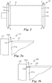
Figure 2 is a front view of a portion of the apparatus ofFigure 1 ; -
Figure 2a is a partial front view of a roll apparatus for carrying out a method according to another embodiment of the present invention; and -
Figure 2b is a partial front view of a roll apparatus for carrying out a method according to still another embodiment of the present invention. - The invention provides a method for applying a metal containing composition to the surface of a web in a predefined pattern, conveying the web over a roll or a belt or a functionally equivalent conveying substrate having a very low thermal mass while simultaneously applying intense heat to the metal containing composition to convert the metal in the composition to a conductive pattern. The substrate is heated and cooled quickly to avoid distortion even when the substrate is kept in continuous motion at commercially viable line speeds.
- Referring to
Figure 1 , a schematic view of anapparatus 10 for carrying out the method of the present invention is illustrated. Acontinuous web 20 of indefinite length is conveyed past applyingstation 22 where ametal containing composition 24 is applied onto a firstmajor surface 23 of theweb 20 in a predefined pattern.Web 20 can be made of any of a variety of materials. In some embodiments,web 20 is a polymeric material selected from the group polyethylene terephthalate (PET), polyethylene naphthalate (PEN), polycarbonate, and polyimide. In embodiments of the invention, applyingstation 22 is a device capable of performing a printing technique to applymetal containing composition 24 to thesurface 23 ofweb 20. In some embodiments, the applyingstation 22 performs ink jet printing (e.g.,station 22 is an ink jet printer). In other embodiments, applyingstation 22 applies themetal containing composition 24 by offset printing, or by rotating screen printing, or by flex gravure printing, or the like. Other techniques for the application of the metal containing composition are contemplated within the scope of the invention. -
Continuous web 20 travels aroundroll 30 in a single direction as indicated by the directional arrow inFigure 1 .Roll 30 has a very low thermal mass. In the embodiment of the invention illustrated inFigure 1 , the very low thermal mass ofroll 30 is provided by mounting athin metal shell 31 on an air bearing 32. The selection of material forthin metal shell 31 is significant in providingroll 30 with a very low thermal mass. In some embodimentsthin metal shell 31 is composed primarily of nickel. In other embodiments, other thin metallic materials can be used. In some embodiments, the thin metal shell is composed of nickel having a thickness of between about 5 mils (0.127 mm) and 15 mils (0.381 mm). Air bearing 32 comprises a non-rotating steel core. Theroll 30 is constructed to require less than 1.0 joule of energy to change 1 cm2 of the surface of the roll by 1°K. In some embodiments, theroll 30 requires less than 0.5 joule of energy to change 1 cm2 of the roll's surface by 1°K. In some embodiments, theroll 30 requires less than 0.2 joule of energy to change 1 cm2 of the roll's surface by 1°K. -
Metal containing composition 24 is applied to thesurface 23 ofweb 20 and is conveyed around theroll 30. Heat is applied to themetal containing composition 24 byheaters 34 to initiate a sintering process that converts the metal in themetal containing composition 24 to provide a finalconductive pattern 36. In embodiments of the invention,heaters 34 are radiant heaters. In some embodiments,heaters 34 are infrared (IR) heaters. Other types of radiant heaters may also be used in the invention as well as resistance heaters, convection heaters, induction heaters and the like as known by those skilled in the art. - Following heating with
heaters 34, theweb 20 is immediately cooled below its glass transition temperature (Tg) prior to the separation of theweb 20 from theroll 30. Cooling of theweb 20 is accomplished using aquenching system 38 mounted downstream fromheaters 34 and adjacent to the outer surface of thethin metal shell 30. In the depicted embodiment,quenching system 38 comprises at least one air knife. Those skilled in the art will appreciate that other devices such as nozzles or other gases may be suitable for use in thequenching system 38. - In some embodiments,
heater 34 may be capable of providing heat energy at a rate sufficient to bucklethin metal shell 30 due to localized thermal expansion. As a preventative measure, embodiments of the invention are equipped to pre-heatthin metal shell 31 to an elevated temperature so that the additional heat provided to the surface of themetal shell 31 byheater 34 will not induce local expansion forces that exceed the thin shell's buckling force threshold. In some embodiments, a baseline heating device is provided for warmingthin metal shell 31 to a predetermined baseline temperature or to a temperature within a predetermined range of temperatures. In some embodiments, baseline heating device is provided in the form shown inFigure 1 , i.e. as a plurality ofresistance heaters 40 mounted inside the air bearing 32. Other configurations for a baseline heating device are also contemplated and will be appreciated by those skilled in the art. - Mathematical modeling of the apparatus of
Figure 1 has suggested that within limits, narrowing the band over which the heating occurs can further reduce the tendency for theweb 20 to buckle. With this in mind,Figure 1a illustrates an alternate embodiment of the apparatus ofFigure 1 showing certain expedients for reducing the width of the heated zone. In this embodiment the output ofheaters 34 is shown focused by alenticular lens 40 and constrained by anaperture 42 on a narrow section of the web. Other expedients that may be used in this way will suggest themselves to the ordinary artisan. By the use of these expedients, the energy is directed to a narrowed section of theweb 20 as it is conveyed aroundthin shell 30, designated in the Figure by angle θ. By way of one or more of these expedients, the angle θ can be advantageously restrained to an arc of less than 2 degrees of the circumference of thethin shell 30. It is contemplated that in some embodiments asecond quenching system 39 might optionally be present to further constrain the zone in which the heating occurs. - In some embodiments, it has been observed that the ambient humidity near the apparatus can have an impact on the process window when following the method according to the present invention. While not wishing to be bound by any theory, it is believed that the moisture content of the tiny amount of air entrained where the
web 20 first contacts theroll 30 may interfere with good contact between the web and the roll when subjected to rapid heating thereby affecting the heat transfer rate. In some embodiments to improve the results, the ambient relative humidity in which the method is conducted can be less than 30%, less than 25%, or even less than 20%. - Referring to
Figure 2 , a front view of theroll 30 ofFigure 1 is shown withthin metal shell 31 mounted onair bearing 32. Typically, theair bearing 32 comprises a cylindrical core having a plurality of holes arranged about the core's periphery, a first circular end cap, and a second circular end cap. A source of compressed gas is supplied to the cylindrical supporting core, which flows out of the holes thereby allowing for rotation of thethin metal shell 31 about the core. Airflow from theair bearing 32 emerging from thelateral edges thin shell 31 is indicated by arrows "A." The width of thethin shell 31 is such that the shell fits within thelateral edges air bearing 32. In the depicted embodiment,thin shell 30 may "wander" laterally, at least to some extent, within the confines of thelateral edges air bearing 32. - Referring now to
Figure 2a , a sectional view of another embodiment of aroll 130 useful in the present invention is shown and will now be described. As described in the foregoing embodiment,thin metal shell 131 is mounted onair bearing 132. Airflow from theair bearing 132 emerges from underneath themetal shell 131 along the lateral edges of the shell as indicated by arrows "A'." The width of thethin shell 131 is such that it the shell fits within the lateral edges ofair bearing 132.Tapered shoulder 133 is provided on the cylindrical core nearlateral edge 132a ofair bearing 132. It will be appreciated that a similar tapered shoulder is provided on the opposite side (not shown) ofair bearing 132. In this manner, taperedshoulder 133 preventsthin metal shell 131 from laterally wandering between the edges ofair bearing 132 and serves to balance forces exerted by lateral airflow A' emerging from the edges of thethin shell 131, thus keeping the thin shell centered on the air bearing. - Referring now to
Figure 2b , a sectional view of another embodiment of aroll 230 useful in the present invention is shown and will now be described.Thin metal shell 231 is mounted onair bearing 232. Airflow from theair bearing 232 emerges from underneath themetal shell 231 along thelateral edge 231a of the shell as indicated by arrows "A"." The width of thethin shell 231 is such that it the shell fits within the lateral edges ofair bearing 232. Stepped shoulder 233 is provided on the cylindrical core nearlateral edge 232a ofair bearing 232. It will be appreciated that a similar structure is provided on the opposite side (not shown) ofair bearing 232. In this manner, stepped shoulder 233 preventsthin metal shell 231 from laterally moving between the edges ofair bearing 132, serving to balance the forces exerted by lateral airflow A" emerging from lateral edges of thethin shell 231, keeping thin shell centered within the edges of the air bearing. - In the foregoing embodiments, the shoulder structures depicted as tapered shoulder 133 (
Figure 2a ) and stepped shoulder 233 (Figure 2b ) are exemplary of structures useful in the present invention to prevent excessive lateral movement of the thin metal shell within the confines of the air bearing. Other structures are contemplated within the scope of the invention to perform the same function and achieve the same result as theshoulders 133 and 233, and the invention is not to be construed as limited in any respect to the depicted shoulder structures. - Additionally, the invention is not to be construed as limited to a conveying surface in the form of a roll comprised of an air bearing and a thin metal shell. Alternate conveying surfaces are contemplated such as, for example, an endless metallic belt in place of a roll described. Further, the ordinary artisan will recognize that it is possible to provide a conveying surface where only a thin contacting layer has a very low thermal mass, that contacting layer being thermally isolated from the rest of the conveying surface by, e.g. a layer of very thermally insulating material disposed immediately below the contacting layer. The foregoing alternative constructions are explicitly considered to be within the scope of the present invention.
- An experimental set-up was prepared similar to that depicted in
Figure 1 , with an axial position stabilizing mechanism generally as depicted in Figure 2c. A web of indefinite length polyethylene terephthalate (PET), 8 inches (20.3 cm) wide and 0.005 inch (0.127 mm) thick, commercially available as ST504 film from DuPont of Wilmington, DE, was threaded up. The roll included a thin shell of primarily nickel, 8.658 inches (21.906 cm) in diameter and 0.010 inch (0.254 mm) thick, commercially available as Nickel Sleeve from Stork Prints America of Charlotte, NC. A shell of this composition requires approximately 0.1 joule of energy to change 1 cm2 of the roll's surface by 1°K. - The nickel shell was mounted around a non-rotating steel supporting core serving as an air bearing. This non-rotating steel supporting core was fitted with 15 - 65 watt strip heaters (commercially available as Thermofoil heaters from Minco of Minneapolis, MN) attached to the inner diameter of the core as baseline heaters. The heat control for the baseline heaters included resistance thermal detector (RTD) feedback to allow for three specific heat zone settings of the core. The supporting air supply for the thin shell acted to transfer heat from the core to the shell as the air passed through holes provided in the steel core. Air pressure of 40 inches of water (0.10 kg/cm2) was provided to the core to support the shell. It was noted that at these settings, the normal temperature differential between the core temperature and the surface of the nickel shell was on the order of 10°C, although it will be noted that this observation was a general guideline, and that the steady state temperature differential when running the web is a function of the web thickness and width as well as line speed.
- An ink composition containing silver nanoparticles suspended in a vehicle (commercially available as CCI-300 from Cabot Corporation of Albuquerque, MN) was dispensed in a predetermined pattern onto the web from an ink jet printing station commercially available as Model SE128 from Dimatix of Lebanon, NH while the web was being advanced at a line speed of 4 feet/minute (1.22 m/min). A heater was provided in the form of two 1600 watt IR heaters (commercially available as lamp and holder model 5193-16-SP735 from Research Inc. of Minneapolis, MN). The IR heaters were fitted with parabolic reflectors to focus the energy to an approximately 0.5 inch wide cross web line. Power to the IR heaters was controlled with a power controller cabinet (model 910-A-240-40-00, Research Inc.). The infrared wavelength of this apparatus was primarily between 1 and 2 microns, which equates to a bulb "temperature" of about 1000 to 2000°C. Exposure of the ink composition to the radiation caused the silver nanoparticles to sinter into a conductive layer of silver which was cooled with a quenching system provided in the form of an air knife positioned downstream from the IR heaters, essentially as shown in
Figure 1 and described elsewhere herein. During operation, the PET web was not thermally distorted and the nickel shell did not buckle. - An experimental set-up was prepared similar to that of Example 1, except as follows. The 1600 watt IR heaters and their focusing and controlling hardware were replaced by a 1500 watt, 25-50 kHz induction heater. This induction heater coil having a 1 inch (2.54 cm) diameter was positioned a distance of 2 mm from the thin shell, and the film was advanced at a speed of 2 feet/min (0.61 m/min). Exposure of the ink composition to the heat generated by the induction heater caused the silver nanoparticles to sinter into a conductive layer of silver which was cooled with a quenching system provided in the form of an air knife positioned downstream from the induction heating coil as described elsewhere herein. During operation, the PET web was not thermally distorted and the nickel shell did not buckle.
- While the invention has been particularly shown and described with reference to various embodiments thereof, it will be understood by those skilled in the art that various other changes in the form and details may be made therein without departing from the scope of the invention as defined by claims.
Claims (15)
- A method of applying a conductive pattern onto a web of indefinite length material, comprising:applying a metal containing composition onto the web to provide a patterned web;conveying the patterned web around a roll having a very low thermal mass;applying heat to the patterned web to convert the metal to a conductive pattern;cooling the conductive pattern;wherein, the applying heat to the patterned web and cooling the conductive pattern are performed while conveying the patterned web around the roll and the term "a roll having a very low thermal mass" defines a roll that reguires no more than 1 joule of energy to change 1 cm2 of the roll's surface by 1°K.
- The method according to claim 1 wherein the roll comprises a thin metal shell mounted on an air bearing.
- The method according to claim 2 wherein the thin metal shell is primarily composed of nickel.
- The method according to claim 2 further comprising a baseline heating device for maintaining the thin metal shell at a predetermined baseline temperature.
- The method according to claim 1 wherein applying heat to the patterned web is accomplished with an infrared energy source and wherein the infrared energy source is focused by a lens on a section of the web while it is being conveyed around the roll.
- The method according to claim 1 wherein the web comprises a film comprising a polymer selected from the group consisting of polyethylene terephthalate, polyethylene naphthalate, polycarbonate, and polyimide.
- The method according to claim 1 wherein the cooling the conductive pattern comprises cooling the web below its glass transition temperature while conveying the patterned web around the roll.
- The method according to claim 7 wherein the cooling is accomplished using a quenching system mounted adjacent to an outer surface of the thin metal shell.
- The method according to claim 8 wherein the quenching system comprises at least one air knife.
- The method according to claim 1 wherein the metal containing composition comprises silver particles suspended in a vehicle, and wherein the applying heat to the patterned web sinters the silver particles into the conductive pattern.
- The method according to claim 3 wherein the thin metal shell is between about 5 mils (0.127 mm) and 15 mils (0.381 mm) thick.
- The method according to claim 1 wherein the roll requires less than 0.5 joule of energy to change 1 cm2 of the roll's surface by 1°K.
- The method according to claim 1 wherein the roll requires less than 0.2 joule of energy to change 1 cm2 of the roll's surface by 1°K.
- The method according to claim 1 wherein applying heat to the patterned web is performed over an arc of no greater than 2 degrees of the circumference of the roll.
- The method according to claim 1 wherein the ambient relative humidity during the applying heat to the patterned web is less than 30%.
Applications Claiming Priority (2)
| Application Number | Priority Date | Filing Date | Title |
|---|---|---|---|
| US5452208P | 2008-05-20 | 2008-05-20 | |
| PCT/US2009/044603 WO2009143206A1 (en) | 2008-05-20 | 2009-05-20 | Method for continuous sintering on indefinite length webs |
Publications (2)
| Publication Number | Publication Date |
|---|---|
| EP2298047A1 EP2298047A1 (en) | 2011-03-23 |
| EP2298047B1 true EP2298047B1 (en) | 2020-02-05 |
Family
ID=40873419
Family Applications (1)
| Application Number | Title | Priority Date | Filing Date |
|---|---|---|---|
| EP09751434.3A Active EP2298047B1 (en) | 2008-05-20 | 2009-05-20 | Method for continuous sintering on indefinite length webs |
Country Status (6)
| Country | Link |
|---|---|
| US (1) | US8720052B2 (en) |
| EP (1) | EP2298047B1 (en) |
| JP (1) | JP2011521476A (en) |
| KR (1) | KR101545372B1 (en) |
| CN (1) | CN102037794B (en) |
| WO (1) | WO2009143206A1 (en) |
Families Citing this family (7)
| Publication number | Priority date | Publication date | Assignee | Title |
|---|---|---|---|---|
| WO2013003253A2 (en) | 2011-06-30 | 2013-01-03 | 3M Innovative Properties Company | Apparatus and method for microcontact printing on indefinite length webs |
| CN103946418A (en) * | 2011-11-22 | 2014-07-23 | 皮考逊公司 | An atomic layer deposition reactor for processing a batch of substrates and method thereof |
| FI125906B (en) * | 2012-01-30 | 2016-03-31 | Stora Enso Oyj | A method and arrangement for transferring electrically conductive material in fluid form onto a printable substrate |
| EP3065951B1 (en) | 2013-11-06 | 2019-07-31 | 3M Innovative Properties Company | Microcontact printing stamps with functional features |
| SE539800C2 (en) * | 2015-05-26 | 2017-12-05 | Stora Enso Oyj | Method and arrangement for producing electrically conductivepatterns on substrates |
| GB201613051D0 (en) * | 2016-07-28 | 2016-09-14 | Landa Labs (2012) Ltd | Applying an electrical conductor to a substrate |
| US11865571B2 (en) | 2019-12-31 | 2024-01-09 | 3M Innovative Properties Company | Die coating on air supported shell |
Family Cites Families (26)
| Publication number | Priority date | Publication date | Assignee | Title |
|---|---|---|---|---|
| US2914996A (en) * | 1953-06-03 | 1959-12-01 | Sprague Electric Co | Electrostatic unit for producing printed circuits |
| US3519253A (en) * | 1966-10-11 | 1970-07-07 | Xerox Corp | Selective xerographic fuser |
| US3529129A (en) * | 1968-02-23 | 1970-09-15 | Xerox Corp | Reflection type flash fuser |
| US3944783A (en) * | 1974-10-18 | 1976-03-16 | Xerox Corporation | High efficiency non-cavity radiant method and apparatus |
| NL7510463A (en) * | 1975-09-05 | 1977-03-08 | Akzo Nv | ARRANGEMENT AND METHOD FOR HEATING WIRES AND WIRES THEREFORE TREATED. |
| US4444487A (en) * | 1979-07-02 | 1984-04-24 | Xerox Corporation | Multiple-flash fuser |
| US4278702A (en) * | 1979-09-25 | 1981-07-14 | Anthony J. Casella | Method of making printed circuit board by induction heating of the conductive metal particles on a plastic substrate |
| JPS5750427A (en) * | 1980-09-12 | 1982-03-24 | Ushio Inc | Annealing device and annealing method |
| DE4117388C2 (en) * | 1991-05-28 | 1994-04-28 | Koenig & Bauer Ag | Roller for guiding a web |
| US5656081A (en) * | 1995-06-07 | 1997-08-12 | Img Group Limited | Press for printing an electrical circuit component directly onto a substrate using an electrically-conductive liquid |
| JPH09127810A (en) * | 1995-10-27 | 1997-05-16 | Minolta Co Ltd | Fixing device by induction heating |
| JP3720152B2 (en) * | 1996-10-16 | 2005-11-24 | トクデン株式会社 | Induction heating roller device |
| GB2319583B (en) * | 1996-11-25 | 1999-09-22 | Ricoh Kk | Device with induction heating roller |
| WO2000061481A1 (en) * | 1999-04-09 | 2000-10-19 | Martin Automatic Inc. | Improved web-handling roller |
| US6725010B1 (en) * | 1999-05-10 | 2004-04-20 | Xerox Corporation | Fusing apparatus having an induction heated fuser roller |
| WO2001048558A1 (en) * | 1999-12-28 | 2001-07-05 | Toshiba Tec Kabushiki Kaisha | Image formation apparatus comprising device for fixing developer on recording medium by induction heating of heating roller |
| JP3578976B2 (en) * | 2000-06-21 | 2004-10-20 | トクデン株式会社 | Induction heating roller device |
| JP2002210510A (en) * | 2001-01-15 | 2002-07-30 | Mitsubishi Heavy Ind Ltd | Apparatus and method for induction heating rolling roll |
| US7194234B2 (en) * | 2001-11-01 | 2007-03-20 | Matsushita Electric Industrial Co., Ltd. | Electromagnetic induction heat generating roller, heating device, and image forming apparatus |
| US6933479B2 (en) * | 2002-03-27 | 2005-08-23 | Harison Toshiba Lighting Corp. | Induction heating roller apparatus and image formation apparatus |
| US7223948B2 (en) | 2002-11-15 | 2007-05-29 | W.E.T. Automotive Systems Ag | Covered conductor and heater formed therewith |
| JP2006514487A (en) * | 2003-03-05 | 2006-04-27 | インチューン サーキッツ オサケ ユキチュア | Conductive pattern manufacturing method |
| KR20060107048A (en) | 2005-04-07 | 2006-10-13 | 삼성전자주식회사 | Heating apparatus and driving method thereof |
| JP2006328479A (en) | 2005-05-26 | 2006-12-07 | Sumitomo Metal Mining Co Ltd | Winding type compound vacuum surface treatment apparatus, and film surface treatment method |
| WO2007106699A1 (en) * | 2006-03-14 | 2007-09-20 | Cabot Corporation | Roll-to-roll manufacturing of electronic and optical materials |
| CN101039532A (en) * | 2007-03-07 | 2007-09-19 | 潍坊共达电讯有限公司 | Reflow-resistance welding electret microphone PCB thickening solder pad and its manufacture method |
-
2009
- 2009-05-20 EP EP09751434.3A patent/EP2298047B1/en active Active
- 2009-05-20 WO PCT/US2009/044603 patent/WO2009143206A1/en active Application Filing
- 2009-05-20 US US12/993,138 patent/US8720052B2/en active Active
- 2009-05-20 CN CN2009801186522A patent/CN102037794B/en not_active Expired - Fee Related
- 2009-05-20 JP JP2011510668A patent/JP2011521476A/en active Pending
- 2009-05-20 KR KR1020107028184A patent/KR101545372B1/en active IP Right Grant
Non-Patent Citations (1)
| Title |
|---|
| None * |
Also Published As
| Publication number | Publication date |
|---|---|
| US8720052B2 (en) | 2014-05-13 |
| EP2298047A1 (en) | 2011-03-23 |
| WO2009143206A1 (en) | 2009-11-26 |
| CN102037794B (en) | 2013-02-13 |
| CN102037794A (en) | 2011-04-27 |
| KR101545372B1 (en) | 2015-08-18 |
| KR20110021895A (en) | 2011-03-04 |
| US20110067234A1 (en) | 2011-03-24 |
| JP2011521476A (en) | 2011-07-21 |
Similar Documents
| Publication | Publication Date | Title |
|---|---|---|
| EP2298047B1 (en) | Method for continuous sintering on indefinite length webs | |
| JP6415188B2 (en) | Fixing device | |
| JP4722981B2 (en) | Apparatus and method for controlling temperature of manufacturing equipment | |
| US20120206527A1 (en) | Radiant heater for print media | |
| KR20150020309A (en) | Infrared processing apparatus and method | |
| JP6542215B2 (en) | Method and apparatus for producing a composite material | |
| JP5398675B2 (en) | How to keep the temperature and size of the medium uniform throughout the preheating zone | |
| CN102602141A (en) | Recording apparatus | |
| JP6622680B2 (en) | Longitudinal stretching device | |
| WO2005101132A2 (en) | Adjusting gloss for a print image | |
| CN102950891A (en) | Recording apparatus | |
| US20110052235A1 (en) | Apparatuses useful in printing and methods of controlling the temperature of surfaces in apparatuses useful in printing | |
| JP2011521476A5 (en) | ||
| MX2020011186A (en) | Method for producing printed nonwoven-film laminates. | |
| JP5372708B2 (en) | Microstructure transfer device | |
| JP2017039579A (en) | Recording device, device and drying device | |
| JP6264823B2 (en) | Recording medium heating apparatus, printing system, and pretreatment system | |
| US11155104B2 (en) | Medium heating device having a second heater for heating a region downstream of a first heater | |
| JP2014069531A (en) | Liquid jet device | |
| JP2007290145A (en) | Temperature control method of laminated metal strip, manufacturing method of laminated metal strip and laminated metal strip manufacturing apparatus | |
| RU2014133100A (en) | METHOD AND INSTALLATION FOR TRANSFER OF ELECTRIC CONDUCTING MATERIAL IN FLUID FORM TO PRINT SUBSTRATE | |
| KR101545052B1 (en) | System for patterning using roll-to-roll | |
| WO2017087475A1 (en) | Process for binding conductive ink to glass | |
| JP6586876B2 (en) | Manufacturing method and manufacturing apparatus for resin film with coating film | |
| JP4669715B2 (en) | Composite material sheet manufacturing equipment |
Legal Events
| Date | Code | Title | Description |
|---|---|---|---|
| PUAI | Public reference made under article 153(3) epc to a published international application that has entered the european phase |
Free format text: ORIGINAL CODE: 0009012 |
|
| 17P | Request for examination filed |
Effective date: 20101210 |
|
| AK | Designated contracting states |
Kind code of ref document: A1 Designated state(s): AT BE BG CH CY CZ DE DK EE ES FI FR GB GR HR HU IE IS IT LI LT LU LV MC MK MT NL NO PL PT RO SE SI SK TR |
|
| AX | Request for extension of the european patent |
Extension state: AL BA RS |
|
| DAX | Request for extension of the european patent (deleted) | ||
| 17Q | First examination report despatched |
Effective date: 20120103 |
|
| GRAP | Despatch of communication of intention to grant a patent |
Free format text: ORIGINAL CODE: EPIDOSNIGR1 |
|
| STAA | Information on the status of an ep patent application or granted ep patent |
Free format text: STATUS: GRANT OF PATENT IS INTENDED |
|
| GRAJ | Information related to disapproval of communication of intention to grant by the applicant or resumption of examination proceedings by the epo deleted |
Free format text: ORIGINAL CODE: EPIDOSDIGR1 |
|
| GRAP | Despatch of communication of intention to grant a patent |
Free format text: ORIGINAL CODE: EPIDOSNIGR1 |
|
| INTG | Intention to grant announced |
Effective date: 20180914 |
|
| RIN1 | Information on inventor provided before grant (corrected) |
Inventor name: NELSON, BRIAN K. Inventor name: STENSVAD, KARL K. Inventor name: SWANSON, RONALD P. Inventor name: KIDANE, SAMUEL Inventor name: CARLSON, DANIEL H. Inventor name: TIEFENBRUCK, GRANT F. Inventor name: THEIS, DANIEL J. Inventor name: DOBBS, JAMES N. |
|
| INTG | Intention to grant announced |
Effective date: 20180925 |
|
| GRAJ | Information related to disapproval of communication of intention to grant by the applicant or resumption of examination proceedings by the epo deleted |
Free format text: ORIGINAL CODE: EPIDOSDIGR1 |
|
| GRAL | Information related to payment of fee for publishing/printing deleted |
Free format text: ORIGINAL CODE: EPIDOSDIGR3 |
|
| GRAS | Grant fee paid |
Free format text: ORIGINAL CODE: EPIDOSNIGR3 |
|
| STAA | Information on the status of an ep patent application or granted ep patent |
Free format text: STATUS: EXAMINATION IS IN PROGRESS |
|
| INTC | Intention to grant announced (deleted) | ||
| GRAP | Despatch of communication of intention to grant a patent |
Free format text: ORIGINAL CODE: EPIDOSNIGR1 |
|
| STAA | Information on the status of an ep patent application or granted ep patent |
Free format text: STATUS: GRANT OF PATENT IS INTENDED |
|
| INTG | Intention to grant announced |
Effective date: 20190404 |
|
| GRAJ | Information related to disapproval of communication of intention to grant by the applicant or resumption of examination proceedings by the epo deleted |
Free format text: ORIGINAL CODE: EPIDOSDIGR1 |
|
| GRAL | Information related to payment of fee for publishing/printing deleted |
Free format text: ORIGINAL CODE: EPIDOSDIGR3 |
|
| STAA | Information on the status of an ep patent application or granted ep patent |
Free format text: STATUS: EXAMINATION IS IN PROGRESS |
|
| INTC | Intention to grant announced (deleted) | ||
| GRAP | Despatch of communication of intention to grant a patent |
Free format text: ORIGINAL CODE: EPIDOSNIGR1 |
|
| STAA | Information on the status of an ep patent application or granted ep patent |
Free format text: STATUS: GRANT OF PATENT IS INTENDED |
|
| INTG | Intention to grant announced |
Effective date: 20190927 |
|
| GRAA | (expected) grant |
Free format text: ORIGINAL CODE: 0009210 |
|
| STAA | Information on the status of an ep patent application or granted ep patent |
Free format text: STATUS: THE PATENT HAS BEEN GRANTED |
|
| AK | Designated contracting states |
Kind code of ref document: B1 Designated state(s): AT BE BG CH CY CZ DE DK EE ES FI FR GB GR HR HU IE IS IT LI LT LU LV MC MK MT NL NO PL PT RO SE SI SK TR |
|
| REG | Reference to a national code |
Ref country code: GB Ref legal event code: FG4D |
|
| REG | Reference to a national code |
Ref country code: AT Ref legal event code: REF Ref document number: 1230851 Country of ref document: AT Kind code of ref document: T Effective date: 20200215 |
|
| REG | Reference to a national code |
Ref country code: DE Ref legal event code: R096 Ref document number: 602009061095 Country of ref document: DE |
|
| REG | Reference to a national code |
Ref country code: IE Ref legal event code: FG4D |
|
| REG | Reference to a national code |
Ref country code: CH Ref legal event code: EP |
|
| REG | Reference to a national code |
Ref country code: NL Ref legal event code: MP Effective date: 20200205 |
|
| PG25 | Lapsed in a contracting state [announced via postgrant information from national office to epo] |
Ref country code: PT Free format text: LAPSE BECAUSE OF FAILURE TO SUBMIT A TRANSLATION OF THE DESCRIPTION OR TO PAY THE FEE WITHIN THE PRESCRIBED TIME-LIMIT Effective date: 20200628 Ref country code: NO Free format text: LAPSE BECAUSE OF FAILURE TO SUBMIT A TRANSLATION OF THE DESCRIPTION OR TO PAY THE FEE WITHIN THE PRESCRIBED TIME-LIMIT Effective date: 20200505 Ref country code: FI Free format text: LAPSE BECAUSE OF FAILURE TO SUBMIT A TRANSLATION OF THE DESCRIPTION OR TO PAY THE FEE WITHIN THE PRESCRIBED TIME-LIMIT Effective date: 20200205 |
|
| PGFP | Annual fee paid to national office [announced via postgrant information from national office to epo] |
Ref country code: DE Payment date: 20200506 Year of fee payment: 12 |
|
| REG | Reference to a national code |
Ref country code: LT Ref legal event code: MG4D |
|
| PG25 | Lapsed in a contracting state [announced via postgrant information from national office to epo] |
Ref country code: IS Free format text: LAPSE BECAUSE OF FAILURE TO SUBMIT A TRANSLATION OF THE DESCRIPTION OR TO PAY THE FEE WITHIN THE PRESCRIBED TIME-LIMIT Effective date: 20200605 Ref country code: GR Free format text: LAPSE BECAUSE OF FAILURE TO SUBMIT A TRANSLATION OF THE DESCRIPTION OR TO PAY THE FEE WITHIN THE PRESCRIBED TIME-LIMIT Effective date: 20200506 Ref country code: BG Free format text: LAPSE BECAUSE OF FAILURE TO SUBMIT A TRANSLATION OF THE DESCRIPTION OR TO PAY THE FEE WITHIN THE PRESCRIBED TIME-LIMIT Effective date: 20200505 Ref country code: SE Free format text: LAPSE BECAUSE OF FAILURE TO SUBMIT A TRANSLATION OF THE DESCRIPTION OR TO PAY THE FEE WITHIN THE PRESCRIBED TIME-LIMIT Effective date: 20200205 Ref country code: LV Free format text: LAPSE BECAUSE OF FAILURE TO SUBMIT A TRANSLATION OF THE DESCRIPTION OR TO PAY THE FEE WITHIN THE PRESCRIBED TIME-LIMIT Effective date: 20200205 Ref country code: HR Free format text: LAPSE BECAUSE OF FAILURE TO SUBMIT A TRANSLATION OF THE DESCRIPTION OR TO PAY THE FEE WITHIN THE PRESCRIBED TIME-LIMIT Effective date: 20200205 |
|
| PG25 | Lapsed in a contracting state [announced via postgrant information from national office to epo] |
Ref country code: NL Free format text: LAPSE BECAUSE OF FAILURE TO SUBMIT A TRANSLATION OF THE DESCRIPTION OR TO PAY THE FEE WITHIN THE PRESCRIBED TIME-LIMIT Effective date: 20200205 |
|
| PG25 | Lapsed in a contracting state [announced via postgrant information from national office to epo] |
Ref country code: DK Free format text: LAPSE BECAUSE OF FAILURE TO SUBMIT A TRANSLATION OF THE DESCRIPTION OR TO PAY THE FEE WITHIN THE PRESCRIBED TIME-LIMIT Effective date: 20200205 Ref country code: ES Free format text: LAPSE BECAUSE OF FAILURE TO SUBMIT A TRANSLATION OF THE DESCRIPTION OR TO PAY THE FEE WITHIN THE PRESCRIBED TIME-LIMIT Effective date: 20200205 Ref country code: LT Free format text: LAPSE BECAUSE OF FAILURE TO SUBMIT A TRANSLATION OF THE DESCRIPTION OR TO PAY THE FEE WITHIN THE PRESCRIBED TIME-LIMIT Effective date: 20200205 Ref country code: RO Free format text: LAPSE BECAUSE OF FAILURE TO SUBMIT A TRANSLATION OF THE DESCRIPTION OR TO PAY THE FEE WITHIN THE PRESCRIBED TIME-LIMIT Effective date: 20200205 Ref country code: SK Free format text: LAPSE BECAUSE OF FAILURE TO SUBMIT A TRANSLATION OF THE DESCRIPTION OR TO PAY THE FEE WITHIN THE PRESCRIBED TIME-LIMIT Effective date: 20200205 Ref country code: CZ Free format text: LAPSE BECAUSE OF FAILURE TO SUBMIT A TRANSLATION OF THE DESCRIPTION OR TO PAY THE FEE WITHIN THE PRESCRIBED TIME-LIMIT Effective date: 20200205 Ref country code: EE Free format text: LAPSE BECAUSE OF FAILURE TO SUBMIT A TRANSLATION OF THE DESCRIPTION OR TO PAY THE FEE WITHIN THE PRESCRIBED TIME-LIMIT Effective date: 20200205 |
|
| REG | Reference to a national code |
Ref country code: DE Ref legal event code: R097 Ref document number: 602009061095 Country of ref document: DE |
|
| REG | Reference to a national code |
Ref country code: AT Ref legal event code: MK05 Ref document number: 1230851 Country of ref document: AT Kind code of ref document: T Effective date: 20200205 |
|
| PLBE | No opposition filed within time limit |
Free format text: ORIGINAL CODE: 0009261 |
|
| STAA | Information on the status of an ep patent application or granted ep patent |
Free format text: STATUS: NO OPPOSITION FILED WITHIN TIME LIMIT |
|
| 26N | No opposition filed |
Effective date: 20201106 |
|
| PG25 | Lapsed in a contracting state [announced via postgrant information from national office to epo] |
Ref country code: IT Free format text: LAPSE BECAUSE OF FAILURE TO SUBMIT A TRANSLATION OF THE DESCRIPTION OR TO PAY THE FEE WITHIN THE PRESCRIBED TIME-LIMIT Effective date: 20200205 Ref country code: CH Free format text: LAPSE BECAUSE OF NON-PAYMENT OF DUE FEES Effective date: 20200531 Ref country code: MC Free format text: LAPSE BECAUSE OF FAILURE TO SUBMIT A TRANSLATION OF THE DESCRIPTION OR TO PAY THE FEE WITHIN THE PRESCRIBED TIME-LIMIT Effective date: 20200205 Ref country code: AT Free format text: LAPSE BECAUSE OF FAILURE TO SUBMIT A TRANSLATION OF THE DESCRIPTION OR TO PAY THE FEE WITHIN THE PRESCRIBED TIME-LIMIT Effective date: 20200205 Ref country code: LI Free format text: LAPSE BECAUSE OF NON-PAYMENT OF DUE FEES Effective date: 20200531 |
|
| PG25 | Lapsed in a contracting state [announced via postgrant information from national office to epo] |
Ref country code: PL Free format text: LAPSE BECAUSE OF FAILURE TO SUBMIT A TRANSLATION OF THE DESCRIPTION OR TO PAY THE FEE WITHIN THE PRESCRIBED TIME-LIMIT Effective date: 20200205 Ref country code: SI Free format text: LAPSE BECAUSE OF FAILURE TO SUBMIT A TRANSLATION OF THE DESCRIPTION OR TO PAY THE FEE WITHIN THE PRESCRIBED TIME-LIMIT Effective date: 20200205 |
|
| REG | Reference to a national code |
Ref country code: BE Ref legal event code: MM Effective date: 20200531 |
|
| GBPC | Gb: european patent ceased through non-payment of renewal fee |
Effective date: 20200520 |
|
| PG25 | Lapsed in a contracting state [announced via postgrant information from national office to epo] |
Ref country code: LU Free format text: LAPSE BECAUSE OF NON-PAYMENT OF DUE FEES Effective date: 20200520 |
|
| PG25 | Lapsed in a contracting state [announced via postgrant information from national office to epo] |
Ref country code: GB Free format text: LAPSE BECAUSE OF NON-PAYMENT OF DUE FEES Effective date: 20200520 Ref country code: FR Free format text: LAPSE BECAUSE OF NON-PAYMENT OF DUE FEES Effective date: 20200531 Ref country code: IE Free format text: LAPSE BECAUSE OF NON-PAYMENT OF DUE FEES Effective date: 20200520 |
|
| PG25 | Lapsed in a contracting state [announced via postgrant information from national office to epo] |
Ref country code: BE Free format text: LAPSE BECAUSE OF NON-PAYMENT OF DUE FEES Effective date: 20200531 |
|
| REG | Reference to a national code |
Ref country code: DE Ref legal event code: R119 Ref document number: 602009061095 Country of ref document: DE |
|
| PG25 | Lapsed in a contracting state [announced via postgrant information from national office to epo] |
Ref country code: DE Free format text: LAPSE BECAUSE OF NON-PAYMENT OF DUE FEES Effective date: 20211201 |
|
| PG25 | Lapsed in a contracting state [announced via postgrant information from national office to epo] |
Ref country code: TR Free format text: LAPSE BECAUSE OF FAILURE TO SUBMIT A TRANSLATION OF THE DESCRIPTION OR TO PAY THE FEE WITHIN THE PRESCRIBED TIME-LIMIT Effective date: 20200205 Ref country code: MT Free format text: LAPSE BECAUSE OF FAILURE TO SUBMIT A TRANSLATION OF THE DESCRIPTION OR TO PAY THE FEE WITHIN THE PRESCRIBED TIME-LIMIT Effective date: 20200205 Ref country code: CY Free format text: LAPSE BECAUSE OF FAILURE TO SUBMIT A TRANSLATION OF THE DESCRIPTION OR TO PAY THE FEE WITHIN THE PRESCRIBED TIME-LIMIT Effective date: 20200205 |
|
| PG25 | Lapsed in a contracting state [announced via postgrant information from national office to epo] |
Ref country code: MK Free format text: LAPSE BECAUSE OF FAILURE TO SUBMIT A TRANSLATION OF THE DESCRIPTION OR TO PAY THE FEE WITHIN THE PRESCRIBED TIME-LIMIT Effective date: 20200205 |