EP2297536B1 - Verfahren und vorrichtung zum trennen von luft - Google Patents
Verfahren und vorrichtung zum trennen von luft Download PDFInfo
- Publication number
- EP2297536B1 EP2297536B1 EP09743200A EP09743200A EP2297536B1 EP 2297536 B1 EP2297536 B1 EP 2297536B1 EP 09743200 A EP09743200 A EP 09743200A EP 09743200 A EP09743200 A EP 09743200A EP 2297536 B1 EP2297536 B1 EP 2297536B1
- Authority
- EP
- European Patent Office
- Prior art keywords
- stream
- oxygen
- feed stream
- pressure column
- column
- Prior art date
- Legal status (The legal status is an assumption and is not a legal conclusion. Google has not performed a legal analysis and makes no representation as to the accuracy of the status listed.)
- Not-in-force
Links
- 238000000034 method Methods 0.000 title claims abstract description 23
- 239000001301 oxygen Substances 0.000 claims abstract description 141
- 229910052760 oxygen Inorganic materials 0.000 claims abstract description 141
- QVGXLLKOCUKJST-UHFFFAOYSA-N atomic oxygen Chemical compound [O] QVGXLLKOCUKJST-UHFFFAOYSA-N 0.000 claims abstract description 140
- IJGRMHOSHXDMSA-UHFFFAOYSA-N Atomic nitrogen Chemical compound N#N IJGRMHOSHXDMSA-UHFFFAOYSA-N 0.000 claims abstract description 108
- 239000007788 liquid Substances 0.000 claims abstract description 105
- MYMOFIZGZYHOMD-UHFFFAOYSA-N Dioxygen Chemical compound O=O MYMOFIZGZYHOMD-UHFFFAOYSA-N 0.000 claims abstract description 57
- 229910052757 nitrogen Inorganic materials 0.000 claims abstract description 54
- QJGQUHMNIGDVPM-UHFFFAOYSA-N nitrogen group Chemical group [N] QJGQUHMNIGDVPM-UHFFFAOYSA-N 0.000 claims abstract description 46
- 230000008016 vaporization Effects 0.000 claims abstract description 25
- 238000009834 vaporization Methods 0.000 claims abstract description 16
- 238000010992 reflux Methods 0.000 claims abstract description 13
- 239000012071 phase Substances 0.000 claims description 27
- 238000004891 communication Methods 0.000 claims description 19
- 238000009833 condensation Methods 0.000 claims description 17
- 230000005494 condensation Effects 0.000 claims description 17
- 238000004821 distillation Methods 0.000 claims description 16
- 238000009835 boiling Methods 0.000 claims description 10
- 239000007791 liquid phase Substances 0.000 claims description 10
- 239000012808 vapor phase Substances 0.000 claims description 9
- 238000000746 purification Methods 0.000 claims description 7
- 239000000356 contaminant Substances 0.000 claims description 6
- 230000000694 effects Effects 0.000 claims description 6
- 238000011144 upstream manufacturing Methods 0.000 claims description 4
- 230000006835 compression Effects 0.000 description 12
- 238000007906 compression Methods 0.000 description 12
- 238000000926 separation method Methods 0.000 description 7
- 238000001816 cooling Methods 0.000 description 4
- 238000012856 packing Methods 0.000 description 4
- 238000013459 approach Methods 0.000 description 3
- 230000008929 regeneration Effects 0.000 description 3
- 238000011069 regeneration method Methods 0.000 description 3
- XKRFYHLGVUSROY-UHFFFAOYSA-N Argon Chemical compound [Ar] XKRFYHLGVUSROY-UHFFFAOYSA-N 0.000 description 2
- CURLTUGMZLYLDI-UHFFFAOYSA-N Carbon dioxide Chemical compound O=C=O CURLTUGMZLYLDI-UHFFFAOYSA-N 0.000 description 2
- 239000003463 adsorbent Substances 0.000 description 2
- 230000001174 ascending effect Effects 0.000 description 2
- 239000003245 coal Substances 0.000 description 2
- 238000002485 combustion reaction Methods 0.000 description 2
- 238000013461 design Methods 0.000 description 2
- 238000001704 evaporation Methods 0.000 description 2
- 230000008020 evaporation Effects 0.000 description 2
- 239000012530 fluid Substances 0.000 description 2
- 238000002309 gasification Methods 0.000 description 2
- 238000004519 manufacturing process Methods 0.000 description 2
- 238000005086 pumping Methods 0.000 description 2
- 238000004088 simulation Methods 0.000 description 2
- GWVKDXOHXJEUCP-UHFFFAOYSA-N [N].[O].[Ar] Chemical compound [N].[O].[Ar] GWVKDXOHXJEUCP-UHFFFAOYSA-N 0.000 description 1
- 230000006978 adaptation Effects 0.000 description 1
- XAGFODPZIPBFFR-UHFFFAOYSA-N aluminium Chemical compound [Al] XAGFODPZIPBFFR-UHFFFAOYSA-N 0.000 description 1
- 229910052782 aluminium Inorganic materials 0.000 description 1
- PNEYBMLMFCGWSK-UHFFFAOYSA-N aluminium oxide Inorganic materials [O-2].[O-2].[O-2].[Al+3].[Al+3] PNEYBMLMFCGWSK-UHFFFAOYSA-N 0.000 description 1
- 229910052786 argon Inorganic materials 0.000 description 1
- 229910002092 carbon dioxide Inorganic materials 0.000 description 1
- 239000001569 carbon dioxide Substances 0.000 description 1
- 230000001419 dependent effect Effects 0.000 description 1
- 238000011161 development Methods 0.000 description 1
- 230000018109 developmental process Effects 0.000 description 1
- 239000011552 falling film Substances 0.000 description 1
- 239000000446 fuel Substances 0.000 description 1
- 229930195733 hydrocarbon Natural products 0.000 description 1
- 150000002430 hydrocarbons Chemical class 0.000 description 1
- 239000012535 impurity Substances 0.000 description 1
- 230000010354 integration Effects 0.000 description 1
- 238000002156 mixing Methods 0.000 description 1
- -1 moisture Substances 0.000 description 1
- 239000002808 molecular sieve Substances 0.000 description 1
- 238000005057 refrigeration Methods 0.000 description 1
- URGAHOPLAPQHLN-UHFFFAOYSA-N sodium aluminosilicate Chemical compound [Na+].[Al+3].[O-][Si]([O-])=O.[O-][Si]([O-])=O URGAHOPLAPQHLN-UHFFFAOYSA-N 0.000 description 1
- 238000001179 sorption measurement Methods 0.000 description 1
- 238000012546 transfer Methods 0.000 description 1
- XLYOFNOQVPJJNP-UHFFFAOYSA-N water Substances O XLYOFNOQVPJJNP-UHFFFAOYSA-N 0.000 description 1
- 238000009736 wetting Methods 0.000 description 1
Images
Classifications
-
- F—MECHANICAL ENGINEERING; LIGHTING; HEATING; WEAPONS; BLASTING
- F25—REFRIGERATION OR COOLING; COMBINED HEATING AND REFRIGERATION SYSTEMS; HEAT PUMP SYSTEMS; MANUFACTURE OR STORAGE OF ICE; LIQUEFACTION SOLIDIFICATION OF GASES
- F25J—LIQUEFACTION, SOLIDIFICATION OR SEPARATION OF GASES OR GASEOUS OR LIQUEFIED GASEOUS MIXTURES BY PRESSURE AND COLD TREATMENT OR BY BRINGING THEM INTO THE SUPERCRITICAL STATE
- F25J3/00—Processes or apparatus for separating the constituents of gaseous or liquefied gaseous mixtures involving the use of liquefaction or solidification
- F25J3/02—Processes or apparatus for separating the constituents of gaseous or liquefied gaseous mixtures involving the use of liquefaction or solidification by rectification, i.e. by continuous interchange of heat and material between a vapour stream and a liquid stream
- F25J3/04—Processes or apparatus for separating the constituents of gaseous or liquefied gaseous mixtures involving the use of liquefaction or solidification by rectification, i.e. by continuous interchange of heat and material between a vapour stream and a liquid stream for air
- F25J3/04406—Processes or apparatus for separating the constituents of gaseous or liquefied gaseous mixtures involving the use of liquefaction or solidification by rectification, i.e. by continuous interchange of heat and material between a vapour stream and a liquid stream for air using a dual pressure main column system
- F25J3/04424—Processes or apparatus for separating the constituents of gaseous or liquefied gaseous mixtures involving the use of liquefaction or solidification by rectification, i.e. by continuous interchange of heat and material between a vapour stream and a liquid stream for air using a dual pressure main column system without thermally coupled high and low pressure columns, i.e. a so-called split columns
-
- F—MECHANICAL ENGINEERING; LIGHTING; HEATING; WEAPONS; BLASTING
- F25—REFRIGERATION OR COOLING; COMBINED HEATING AND REFRIGERATION SYSTEMS; HEAT PUMP SYSTEMS; MANUFACTURE OR STORAGE OF ICE; LIQUEFACTION SOLIDIFICATION OF GASES
- F25J—LIQUEFACTION, SOLIDIFICATION OR SEPARATION OF GASES OR GASEOUS OR LIQUEFIED GASEOUS MIXTURES BY PRESSURE AND COLD TREATMENT OR BY BRINGING THEM INTO THE SUPERCRITICAL STATE
- F25J3/00—Processes or apparatus for separating the constituents of gaseous or liquefied gaseous mixtures involving the use of liquefaction or solidification
- F25J3/02—Processes or apparatus for separating the constituents of gaseous or liquefied gaseous mixtures involving the use of liquefaction or solidification by rectification, i.e. by continuous interchange of heat and material between a vapour stream and a liquid stream
- F25J3/04—Processes or apparatus for separating the constituents of gaseous or liquefied gaseous mixtures involving the use of liquefaction or solidification by rectification, i.e. by continuous interchange of heat and material between a vapour stream and a liquid stream for air
- F25J3/04006—Providing pressurised feed air or process streams within or from the air fractionation unit
- F25J3/04078—Providing pressurised feed air or process streams within or from the air fractionation unit providing pressurized products by liquid compression and vaporisation with cold recovery, i.e. so-called internal compression
- F25J3/0409—Providing pressurised feed air or process streams within or from the air fractionation unit providing pressurized products by liquid compression and vaporisation with cold recovery, i.e. so-called internal compression of oxygen
-
- F—MECHANICAL ENGINEERING; LIGHTING; HEATING; WEAPONS; BLASTING
- F25—REFRIGERATION OR COOLING; COMBINED HEATING AND REFRIGERATION SYSTEMS; HEAT PUMP SYSTEMS; MANUFACTURE OR STORAGE OF ICE; LIQUEFACTION SOLIDIFICATION OF GASES
- F25J—LIQUEFACTION, SOLIDIFICATION OR SEPARATION OF GASES OR GASEOUS OR LIQUEFIED GASEOUS MIXTURES BY PRESSURE AND COLD TREATMENT OR BY BRINGING THEM INTO THE SUPERCRITICAL STATE
- F25J3/00—Processes or apparatus for separating the constituents of gaseous or liquefied gaseous mixtures involving the use of liquefaction or solidification
- F25J3/02—Processes or apparatus for separating the constituents of gaseous or liquefied gaseous mixtures involving the use of liquefaction or solidification by rectification, i.e. by continuous interchange of heat and material between a vapour stream and a liquid stream
- F25J3/04—Processes or apparatus for separating the constituents of gaseous or liquefied gaseous mixtures involving the use of liquefaction or solidification by rectification, i.e. by continuous interchange of heat and material between a vapour stream and a liquid stream for air
- F25J3/04248—Generation of cold for compensating heat leaks or liquid production, e.g. by Joule-Thompson expansion
- F25J3/04284—Generation of cold for compensating heat leaks or liquid production, e.g. by Joule-Thompson expansion using internal refrigeration by open-loop gas work expansion, e.g. of intermediate or oxygen enriched (waste-)streams
- F25J3/0429—Generation of cold for compensating heat leaks or liquid production, e.g. by Joule-Thompson expansion using internal refrigeration by open-loop gas work expansion, e.g. of intermediate or oxygen enriched (waste-)streams of feed air, e.g. used as waste or product air or expanded into an auxiliary column
- F25J3/04303—Lachmann expansion, i.e. expanded into oxygen producing or low pressure column
-
- F—MECHANICAL ENGINEERING; LIGHTING; HEATING; WEAPONS; BLASTING
- F25—REFRIGERATION OR COOLING; COMBINED HEATING AND REFRIGERATION SYSTEMS; HEAT PUMP SYSTEMS; MANUFACTURE OR STORAGE OF ICE; LIQUEFACTION SOLIDIFICATION OF GASES
- F25J—LIQUEFACTION, SOLIDIFICATION OR SEPARATION OF GASES OR GASEOUS OR LIQUEFIED GASEOUS MIXTURES BY PRESSURE AND COLD TREATMENT OR BY BRINGING THEM INTO THE SUPERCRITICAL STATE
- F25J2200/00—Processes or apparatus using separation by rectification
- F25J2200/50—Processes or apparatus using separation by rectification using multiple (re-)boiler-condensers at different heights of the column
- F25J2200/54—Processes or apparatus using separation by rectification using multiple (re-)boiler-condensers at different heights of the column in the low pressure column of a double pressure main column system
-
- F—MECHANICAL ENGINEERING; LIGHTING; HEATING; WEAPONS; BLASTING
- F25—REFRIGERATION OR COOLING; COMBINED HEATING AND REFRIGERATION SYSTEMS; HEAT PUMP SYSTEMS; MANUFACTURE OR STORAGE OF ICE; LIQUEFACTION SOLIDIFICATION OF GASES
- F25J—LIQUEFACTION, SOLIDIFICATION OR SEPARATION OF GASES OR GASEOUS OR LIQUEFIED GASEOUS MIXTURES BY PRESSURE AND COLD TREATMENT OR BY BRINGING THEM INTO THE SUPERCRITICAL STATE
- F25J2205/00—Processes or apparatus using other separation and/or other processing means
- F25J2205/02—Processes or apparatus using other separation and/or other processing means using simple phase separation in a vessel or drum
-
- F—MECHANICAL ENGINEERING; LIGHTING; HEATING; WEAPONS; BLASTING
- F25—REFRIGERATION OR COOLING; COMBINED HEATING AND REFRIGERATION SYSTEMS; HEAT PUMP SYSTEMS; MANUFACTURE OR STORAGE OF ICE; LIQUEFACTION SOLIDIFICATION OF GASES
- F25J—LIQUEFACTION, SOLIDIFICATION OR SEPARATION OF GASES OR GASEOUS OR LIQUEFIED GASEOUS MIXTURES BY PRESSURE AND COLD TREATMENT OR BY BRINGING THEM INTO THE SUPERCRITICAL STATE
- F25J2250/00—Details related to the use of reboiler-condensers
- F25J2250/04—Down-flowing type boiler-condenser, i.e. with evaporation of a falling liquid film
Definitions
- the present invention relates to a method and apparatus for separating an oxygen and nitrogen containing stream, for example, air, utilizing a higher pressure column and a lower pressure column in which lower pressure column reboil is produced at two or more locations. More particularly, the present invention relates to such a method in which a portion of the feed air is substantially condensed to produce reboil at the bottom of the lower pressure column, another portion of the air, which is fed at lower pressure, provides low pressure column reboil above that produced by the portion of the air fed to produce the bottom reboil and at least both feed air streams are, at least in part, distilled in the higher pressure column.
- oxygen is used in the gasification of coal and in oxy-fuel combustion.
- the oxygen is typically generated in an air separation plant by the cryogenic rectification of air.
- the air separation plant requires the air be compressed and therefore, it is desirable that such energy expenditure be as small as possible to maximize the amount of electrical power that is available for uses outside of the plant.
- Cryogenic air separation plants typically employ a higher pressure column and a lower pressure column.
- the incoming air is compressed and introduced into the higher pressure column.
- the feed air is rectified to produce a nitrogen-rich overhead and a crude liquid oxygen column bottoms.
- the oxygen-rich column bottoms liquid is further refined in the lower pressure column to produce an oxygen-rich liquid that is reboiled against condensing the nitrogen-rich overhead produced in the higher pressure column.
- the condensation of the nitrogen-rich overhead produces nitrogen-rich liquid that is used to reflux both the higher pressure column and the lower pressure column. Some of the nitrogen-rich liquid can be taken as a product.
- the operational pressure of the higher pressure column has to be set so that the oxygen-rich liquid is able to condense the nitrogen-rich vapor of the higher pressure column.
- the actual power consumed is strongly dependent upon how effectively energy/vapor flow is introduced into the lower sections of the lower pressure column in which nitrogen is stripped from the descending oxygen-rich liquid.
- the performance of the nitrogen stripping section is far from ideal resulting in inefficiency and therefore an opportunity to reduce air separation power consumption.
- JP-A-0896961 there is known a method of producing an oxygen product from a feed stream comprising oxygen and nitrogen, said method comprising:
- U.S. Patent No. 5,551,258 discloses an air separation method producing low purity oxygen in which the higher pressure column overhead and the base of the lower pressure column are effectively decoupled.
- air is compressed to successively higher pressures to produce a higher pressure air stream and a lower pressure air stream.
- the higher pressure air stream reboils the bottom of the lower pressure column and the lower pressure column stream reboils an intermediate location of the nitrogen stripping section of the lower pressure column. Both of these streams are thereby liquefied or at the very least, substantially condensed and introduced into the higher pressure column for rectification.
- a stream of crude liquid oxygen from the higher pressure column is subcooled and then partially vaporized against condensing some of the reflux required for the higher pressure column.
- the resulting vaporized crude liquid oxygen is phase separated and the liquid and vapor phases are introduced into successively higher portions of the lower pressure column rather than in the nitrogen stripping section.
- intermediate reboilers present in the lower pressure column represent an expense because the lower pressure column must necessarily be made taller to accommodate the reboilers. Additionally, adding the crude liquid oxygen directly into the upper portions of the lower pressure column does not increase the efficiency of the nitrogen stripping section, In fact, additional mixing irreversibility is incurred through this direct introduction.
- the present invention provides a method and apparatus for the production of low purity oxygen which is less expensive to fabricate than the prior art and further improves the efficiency of the stripping section of the lower pressure column.
- the present invention provides a method of producing an oxygen product from a feed stream comprising oxygen and nitrogen as it is defined in claim 1.
- a first part of the feed stream is partially condensed and a stream made up, at least in part, of a second part of the feed stream is condensed.
- the partial condensation of the first part and the substantial condensation of the second part occurs after the first part of the feed stream has been compressed, the second part of the feed stream has been compressed to a higher pressure than that of the first part of the feed stream and the first part of the feed stream and the second part of the feed stream are cooled within a main heat exchange zone.
- the first part of the feed stream is condensed and introduced into the higher pressure column of a distillation column system. Liquid that results from the condensation of the stream made up, at least in part, of the second part of the feed stream is rectified within the higher pressure column and a lower pressure column of the distillation column system.
- a first crude liquid oxygen stream primarily composed of a crude liquid oxygen column bottoms of the higher pressure column is partially vaporized through indirect heat exchange with a nitrogen-rich stream composed of nitrogen-rich column overhead produced in the higher pressure column, thereby producing a liquid nitrogen containing stream.
- the liquid nitrogen containing stream is utilized as reflux to the higher pressure column and the lower pressure column.
- Liquid and vapor phases are disengaged from the first crude liquid oxygen stream, after having been partially vaporized, to form a crude oxygen vapor stream and a second crude liquid oxygen stream.
- An oxygen containing stream that is made up, at least in part, of the second crude liquid oxygen stream is passed in indirect heat exchange with the first part of the feed stream. This affects the condensation of the first part of the feed stream and at least partially vaporizes the oxygen containing stream.
- the crude oxygen vapor stream is introduced along with the oxygen containing stream, after having been at least partially vaporized, into successively lower points than the lower pressure column.
- introduction of the oxygen containing stream may be introduced as a single stream into the lower pressure column or alternatively, vapor and liquid fractions may be disengaged and introduced as two separate streams into the lower pressure column.
- introduction when used in connection with the introduction of the oxygen containing stream into the lower pressure column is therefore, meant to cover both possibilities.
- Boil-up is produced within a bottom portion of the lower pressure column by at least partially vaporizing an oxygen-rich liquid column bottoms produced within the lower pressure column by indirect heat exchange with the stream, made up at least in part, of the second part of the feed stream. This effects the condensation of the stream made up at least in part of the second part of the feed stream.
- the oxygen product stream is formed from either residual liquid or vapor produced from the at least partial vaporization of the oxygen-rich liquid column bottoms stream.
- An oxygen and nitrogen containing liquid stream can be withdrawn from the lower pressure column at a point of introduction of the crude oxygen vapor stream.
- the oxygen and nitrogen containing liquid stream can be combined with a second crude liquid oxygen stream to form the oxygen containing stream.
- the oxygen-rich liquid column bottoms can be partially vaporized within a heat exchanger located outside of the lower pressure column. Boil-up vapor is disengaged from the residual liquid contained in the oxygen-rich liquid column bottoms after having been partially vaporized.
- a boil-up vapor stream is introduced into the bottom region of the lower pressure column to produce the boil-up and a stream of the residual liquid is utilized as the oxygen product stream.
- the oxygen product stream can be pumped and vaporized within the main heat exchange zone.
- the first part of the feed stream is compressed to a first pressure and the second part of the feed stream is compressed to a second pressure higher than that of the first pressure.
- a third part of the feed stream can be further compressed to a third pressure higher than the second pressure and introduced into the main heat exchange zone to effect the vaporization of the oxygen product stream after having been pumped.
- a first portion of the third part of the feed stream is withdrawn from the main heat exchange zone after having been partially cooled and expanded within a turboexpander to produce an exhaust stream that is in turn introduced into the lower pressure column.
- a second portion of the third part of the feed stream can be fully cooled and liquefied within the main heat exchange zone and expanded to the second pressure to allow its combination with the second part of the feed stream.
- the liquid nitrogen containing stream can be divided into a first part and a second part.
- the first part of the liquid nitrogen containing stream refluxes the lower pressure column and the second part of the liquid nitrogen containing stream refluxes the higher pressure column.
- a nitrogen product stream that is composed of nitrogen containing column overhead of the lower pressure column can be used to subcool the second part of the liquid nitrogen containing stream, the first crude liquid oxygen column bottoms stream and the stream made up, at least in part, of the second part of the feed stream after having been condensed through indirect heat exchange therewith.
- the stream made up, at least in part, of the second part of the feed stream after having been subcooled can be divided into first and second subsidiary streams.
- the first crude liquid oxygen column bottoms stream, the second part of the liquid nitrogen containing stream and the first and second subsidiary streams can each be expanded.
- the first and second subsidiary streams are then respectively introduced into the higher pressure column and the lower pressure column.
- the nitrogen product stream is introduced into the main heat exchange zone and fully warmed.
- the first part of the feed stream and the second part of the feed stream can be compressed to the first pressure and the second pressure, respectively, by compressing the feed stream in a first compressor and purifying the feed stream of higher boiling contaminants.
- the feed stream after having been purified is divided into the first part of the feed stream and the second part of the feed stream.
- the second part of the feed stream can be compressed in a second compressor.
- the third part of the feed stream can be compressed in a third compressor.
- the present invention provides an apparatus for producing an oxygen product from a feed stream comprising oxygen and nitrogen as it is defined in claim 8.
- a first compressor is provided to compress a first part of the feed stream to a first pressure and a second compressor is employed to compress a second part of the feed stream to a second pressure.
- the second pressure is greater than the first pressure.
- a main heat exchange zone is in flow communication with the first compressor and the second compressor and is configured to cool the first part of the feed stream and the second part of the feed stream through indirect heat exchange with return streams produced from cryogenic rectification of air.
- the return streams include an oxygen product stream composed of the oxygen product.
- a first heat exchanger is interposed between the main heat exchange zone and a higher pressure column of a distillation column system comprising the higher pressure column and a lower pressure column.
- the first heat exchanger is configured to partially condense the first part of the feed stream through indirect heat exchange with an oxygen containing stream formed at least in part from a second crude liquid oxygen stream. This at least partially vaporizes the oxygen containing stream.
- the first heat exchanger is connected to the higher pressure column so as to introduce the first part of the feed stream after having been partially condensed within the first heat exchanger into the higher pressure column.
- a second heat exchanger is provided in flow communication with the main heat exchange zone and the lower pressure column of the distillation column system.
- the second heat exchanger is configured to condense a stream made up at least in part of the second part of the feed stream through indirect heat exchange with an oxygen-rich liquid column bottoms stream composed of an oxygen-rich liquid column bottoms produced within the lower pressure column.
- the heat exchange at least partially vaporizes the oxygen-rich liquid column bottoms stream.
- the second heat exchanger is in flow communication with the higher pressure column and the lower pressure column so as to introduce first and second portions of the stream made up at least in part of second part of the feed stream, after condensation in the second heat exchanger, into the higher pressure column and the lower pressure column, respectively. This rectifies liquid resulting from the substantial condensation.
- a third heat exchanger is connected to the high pressure distillation column and is configured to partially vaporize a first crude liquid oxygen stream primarily composed of crude liquid oxygen column bottoms produced in the higher pressure column through indirect heat exchange with a nitrogen-rich stream composed of nitrogen-rich column overhead produced in the higher pressure column. This produces a liquid nitrogen containing stream.
- the third heat exchanger is also in flow communication with both the higher pressure column and the lower pressure column so that the lower pressure column is refluxed with a first part of the liquid nitrogen containing stream and the higher pressure column is refluxed with a second part of the liquid nitrogen containing stream.
- a phase separator is connected to the third heat exchanger so as to disengage liquid and vapor phases from the first crude liquid oxygen stream after having been partially vaporized to form a crude oxygen vapor stream and the second crude liquid oxygen stream.
- the phase separator and the first heat exchanger are also connected to the lower pressure column of the distillation column system such that the crude oxygen vapor stream and the oxygen containing stream after having been at least partially vaporized are introduced into successively lower points in the lower pressure column.
- the second heat exchanger is also in flow communication with the lower pressure column such that boil-up is produced within a bottom portion of the lower pressure column through at least partial vaporization of an oxygen-rich liquid bottoms stream.
- the second heat exchanger is also in flow communication with the main heat exchange zone such that the oxygen product stream is formed from residual liquid or vapor produced from the at least partial vaporization of the oxygen-rich liquid column bottoms and is introduced into the main heat exchange zone.
- a first conduit can be connected to the lower pressure column such that an oxygen and nitrogen containing stream is withdrawn from the lower pressure column at a point of introduction of the crude oxygen vapor stream.
- a second conduit can be connected between the phase separator and the first heat exchanger and connected to the first conduit such that the oxygen and nitrogen containing stream is combined with the second crude liquid oxygen stream upstream of the first heat exchanger so as to form the oxygen containing stream.
- the phase separator can be a first phase separator.
- a second phase separator can be connected to the second heat exchanger to disengage boil-up vapor from the residual liquid contained in the oxygen-rich liquid column bottoms stream after having been at least partially vaporized.
- the second phase separator is connected to the bottom region of the lower pressure column so that a boil-up vapor stream is introduced into the bottom region of the lower pressure column to produce the boil-up.
- the second phase separator is also in flow communication with the main heat exchange zone so as to introduce a stream of the residual liquid into the main heat exchange zone and thereby to form the oxygen product stream.
- a pump can be positioned to pressurize the oxygen product stream.
- the pump is connected to the main heat exchange zone so that the oxygen product stream after having been pressurized is vaporized within the main heat exchange zone.
- a third compressor can be connected to the main heat exchange zone to compress a third part of the feed stream to a third pressure, higher than the second pressure, to effect the vaporization of the oxygen product stream after having been pumped.
- the main heat exchange zone is configured such that a first portion of the third part of the feed stream is discharged from the main heat exchange zone after having been partially cooled.
- An expander can be connected to the main heat exchange zone so that the first portion of the third part of the feed stream is expanded, thereby to produce an exhaust stream.
- the expander is also connected to the lower pressure column so that the exhaust stream is introduced into the lower pressure column.
- the main heat exchange zone is also configured such that a second portion of the third part of the feed stream is fully cooled and liquefied within the main heat exchange zone.
- An expansion device can be connected to the main heat exchange zone and in flow communication with the second heat exchange such that the second portion of the third part of the feed stream is expanded to the second pressure and combined with the second part of the feed stream upstream of the second heat exchanger.
- a subcooling unit can be connected to a top portion of the lower pressure column, the second heat exchanger, the higher pressure column and the third heat exchanger.
- the subcooling unit is configured such that a nitrogen product stream composed of a nitrogen-rich containing column overhead of the lower pressure column subcools the second part of the nitrogen containing liquid stream, the first crude liquid oxygen column bottoms stream and a stream made up, at least in part, of the second part of the feed stream after having been condensed.
- the subcooling unit is also in flow communication with the higher and the lower pressure columns such that the stream made up, at least in part of the second part of the feed stream after having been subcooled is divided into first and second subsidiary streams and introduced into the higher and lower pressure columns.
- First and second expansion valves can be interposed between the subcooling unit and the higher and lower pressure columns to expand the first and second subsidiary streams to the higher column pressure and the lower column pressure, respectively.
- the subcooling unit is also connected to the main heat exchange zone such that the nitrogen product stream is introduced into the main heat exchange zone and fully warmed.
- a purification unit can be connected to the first compressor to purify the feed stream of higher boiling contaminants.
- the second compressor can be connected to the purification unit such that the feed stream, after having been purified, is divided into the first part of the feed stream and the second part of the feed stream to be compressed in the second compressor.
- a third compressor can also be connected to the purification such that the feed stream, after having been purified, is also divided into a third part of the feed stream and the third part of the feed stream is compressed in the third compressor.
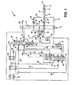
- Apparatus 1 is illustrated separating air or other oxygen and nitrogen containing stream to produce an oxygen product in accordance with the present invention.
- Apparatus 1 is designed to produce a low purity oxygen product namely, a product having an oxygen purity of between about 90 percent and about 98.5 percent.
- reboil is provided within the lower pressure column by condensation of portions of the feed air.
- the low purity oxygen product has a higher concentration of argon than would exist in a distillation column unit in which high pressure column overhead/nitrogen reboils the bottom of low pressure column.
- a feed stream 10 that comprises of oxygen and nitrogen, for instance air.
- a first compressor 12 is provided as a base load air compressor to compress the feed stream 10 to a pressure in a range from between about 2.5 bara and about 3.0 bara.
- the first air compressor 12 may comprise multiple stages of compression and/or intercooling.
- feed air stream 10 is further cooled in an after cooler 14 near ambient temperatures.
- feed stream 10 can be further cooled in a refrigerated after cooler 16 which may comprise a direct contact cooler or heat exchanger, either of which may use combinations of ambient and/or chilled water to absorb the heat of compression and to reduce the moisture content of the compressed air.
- the resultant compressed and cooled feed stream 10 can be purified within a prepurification unit 18 to remove higher boiling contaminants such as moisture, carbon dioxide and hydrocarbons.
- prepurification unit typically contains beds of alumina and/or molecular sieve operating in accordance with a temperature and/or pressure swing adsorption cycle in which moisture and other higher boiling impurities are adsorbed. While one bed is operating, another bed is regenerated.
- the feed stream 10 after having been compressed and purified is divided into a first part 20, a second part 22 and a third part 23.
- the second part 22 of feed stream 10 is compressed in a second compressor 24 and the third part 23 of feed stream 10 is compressed in a third compressor 26.
- Second compressor 24 can compress second part 22 of feed stream 10 to a pressure of between about 4 and about 4.5 bara.
- Third compressor 26 compresses third part 23 of feed stream 10 to a yet even higher pressure.
- Second compressor 24 and third compressor 26 can each comprise multiple stages of compression with intercooling between stages.
- First part 20 of feed stream 10 and second part 22 of feed stream 10 and third part 23 of feed stream 10, after removal of heat of compression by after coolers 28 and 30, respectively, are introduced into a main heat exchanger 32.
- First part 20 of feed stream 10 is cooled to near saturation in main heat exchanger 32 and exits near its saturation temperature.
- Such stream is then partially condensed within a heat exchanger 34.
- a typical exit vapor fraction is in a range of between about 75 percent and about 95 percent.
- the resultant partially condensed stream is then introduced into a higher pressure column 36 to serve as the primary gaseous feed to said column.
- the first part 20 of feed stream 10 could be phase separated and the respected vapor and liquid fractions could be fed independently into higher pressure column 36.
- first part 20 of feed stream 10 constitutes the major portion of the feed to apparatus 1, energy is saved that would otherwise be expended in compression because such stream is not compressed any further. Moreover, since the pressure to which such stream is compressed is much lower than that of a conventional distillation column unit additional energy savings are achieved.
- Third part 23 of feed stream 10 after having been further compressed, is preferably partially cooled within main heat exchanger 32 and divided into a first fraction 38 and a second fraction 40.
- Second fraction 40 is thus partially cooled and can be introduced into a turboexpander 42 to produce an exhaust stream 44 that is introduced into a lower pressure column 46.
- the term "partially cooled” means cooled to a temperature between the warm and cold ends of main heat exchanger 32. It is to be noted that refrigeration can be generated in a number of ways. In the illustrated embodiment, upper column air expansion is used. However, a portion of nitrogen-rich stream 76, to be discussed, could be expanded for similar purposes. Other known methods could be used. Further, the shaft work of expansion can be used in a number of ways, for example, booster air compression or to drive a variable or fixed speed generator. The resulting power may be employed for other compression, pumping or exported for distribution.
- compressors 24 and 26 could be integrated. These compression stages may be integrated into a single machine with a combined motor. Alternatively, the compression may be integrated into the base load compressor 12. All of the compression stages may be driven off of the same motor. For very large plant applications, it may be advantageous to compress two separate streams, for example, second part 22 of feed stream 10 and third part 23 of feed stream 10 may be compressed independently of first part 20 of feed stream 10. In this arrangement it may be advantageous to employ separate pre-purification units 18. Each compression train would possess its own cooling and pretreatment means.
- First fraction 38 is fully cooled. It serves to vaporize a pumped liquid oxygen stream to be discussed and as such, in the illustrated embodiment is liquefied.
- First fraction 38 is thereupon reduced in pressure by an expansion valve 124 and combined with second part, 22 feed stream 10 to produce a combined stream 48 that is condensed within a heat exchanger 50.
- the resultant condensed combined stream 48 is then passed through a subcooling unit 52 and divided into a first portion 54 and a second portion 56.
- First portion 54 is expanded within an expansion valve 58 to a pressure compatible with that of higher pressure column 36 and introduced into an intermediate location thereof.
- Second portion 56 is expanded by an expansion valve 60 and introduced into the lower pressure column 46.
- Higher pressure column 36 and lower pressure column 46 are so called because higher pressure column 36 operates at a higher pressure than lower pressure column 46. Both columns contain mass transfer contacting elements such as structured packing, random packing or sieve trays. With respect to higher pressure column 36, structured packing elements 62 and 64 are illustrated. As to lower pressure column 46, structured packing elements 66, 68, 70 and 72 are illustrated.
- the introduction of first part 20 of feed stream 10 into higher pressure column 36 along with first fraction 54 of combined stream 48 produces an ascending vapor phase and a descending liquid phase within higher pressure column 36.
- the ascending vapor phase becomes ever more rich in the lower boiling or more volatile components as it ascends and the liquid phase becomes ever more rich in the higher boiling components to produce a crude liquid oxygen column bottoms 74 and a nitrogen-rich column overhead.
- Part of the nitrogen-rich column overhead is extracted as a nitrogen-rich stream 76 that is condensed within a heat exchanger 78 to produce a liquid nitrogen containing stream 80.
- a first part 82 of the liquid nitrogen containing stream 80 is used to reflux the lower pressure column 46 and a second part 84 of liquid nitrogen containing stream 80 is used to reflux the higher pressure column 36.
- First part 82 of liquid nitrogen containing stream 80 is subcooled within a subcooling unit 86 and then is reduced in pressure by an expansion valve 88 prior to its introduction into lower pressure column 46 as reflux.
- a first crude liquid oxygen stream 90 composed of the crude liquid oxygen column bottoms 74 is subcooled within a subcooling unit 92 and is then reduced in pressure and temperature by an expansion valve 94.
- First crude liquid oxygen stream is then passed through heat exchanger 78 to condense the nitrogen-rich stream 76. This partially vaporizes first crude liquid oxygen stream 90 that has a vapor fraction in a range of between about 70 percent and about 90 percent.
- Liquid and vapor phases are disengaged from the first crude liquid oxygen stream 90 after the partial vaporization thereof in a phase separator 96. This disengagement produces a second crude liquid oxygen stream 98 and a crude oxygen vapor stream 100.
- Crude oxygen vapor stream 100 is introduced into the lower pressure column 46.
- An oxygen and nitrogen containing liquid stream 102 can be withdrawn from the lower pressure column 46 at a liquid collection point at or near the introduction of crude oxygen vapor stream 100 and then combined with second crude liquid oxygen stream 98 to produce a oxygen containing stream 104.
- a first conduit would lead from the liquid collection point of the lower pressure column and merge with a second conduit leading from the phase separator 96.
- a mechanical pump (not shown) may be employed for this purpose (if the coldbox layout dictates its need). However, this is optional and oxygen containing stream 104 could be made up entirely of second crude liquid oxygen stream 98.
- Oxygen containing stream 104 is introduced into heat exchanger 34 to partially condense first part 20 of feed stream 10 resulting in partial vaporization of the oxygen containing stream 104.
- An embodiment of the present invention is possible in which the heat exchange stream 104 is fully vaporized. In any case of a partial vaporization, at least about 50 percent vaporization of heat exchange stream 104 is possible. However, a vaporization of between about 70 percent and about 90 percent is preferred.
- Oxygen containing stream 104 is thereafter introduced into lower pressure column 72 below the point of introduction of crude oxygen vapor stream 100 to strip nitrogen from the descending liquid phase within the lower pressure column 46.
- Boil-up is produced within lower pressure column 46 by partially vaporizing an oxygen-rich liquid column bottoms stream 106 through indirect heat exchange with combined stream 48 within heat exchanger 50.
- the boil-up vapor is disengaged from residual liquid contained within the oxygen-rich liquid column bottoms stream 106 within a phase separator 108 to produce residual liquid 110 and a boil-up vapor stream 112 that is reintroduced into the bottom region of lower pressure column 46.
- oxygen-rich liquid column bottoms stream 106 could be fully vaporized.
- the residual liquid stream 114 is pumped within a pump 116 and then fully vaporized within main heat exchanger 32 to produce oxygen product stream 118. Another possibility is to produce a product stream from vaporized oxygen.
- the vaporization of pumped liquid oxygen is optional.
- the pumped liquid oxygen produced by pumping residual liquid stream 114 may be warmed and vaporized within a segregated product boiler-vessel or within designated exchanger passes integrated into the main heat exchanger 32.
- the term, "main heat exchange zone" is used herein and in the claims to encompass a segregated product boiler vessel, a single main heat exchanger 32 as illustrated and also, in which warm and cold ends thereof are separate units.
- all of the heat exchangers 34, 50 and 78 operate in a "once-through” fashion. In particular, the boiling fluid proceeds through exchanger only once.
- At least the vapor fraction is then directed into the column system (as opposed to a recirculated boiler/thermo-siphon).
- a recirculated boiler/thermo-siphon In the design of brazed aluminum heat exchangers, it is known in the art to combine heat exchangers into a single package. For example, such a method may be employed in the integration of heat exchangers 78 and 50 or alternatively, heat exchangers 34 and 50.
- the subject exchanger may be incorporated with the associated phase separator 96 or 108.
- the use of falling film (i.e. down flow) evaporators may be employed to reduce the respective temperature approaches on the various heat exchangers 34, 50 and 78.
- the use of a down flow evaporator is of particular utility to heat exchanger 78. Since the nitrogen condenses at essentially constant pressure and temperature, the exchanger approach is independent of flow direction (there is no thermodynamic penalty for employing a down flow exchanger in such a service). In the case of down flow evaporation, the preferred flow path/direction is likely to be co-current - oxygen-rich fluid boils in the same direction in which the condensing stream flows. It should be noted that down flow evaporators may optionally employ a small recirculation pump for purposes of maintaining full wetting of the heat exchange surface.
- the heat exchanger 34 may alternatively employ a stream of liquid taken from the liquid collector located just above the point of introduction of crude oxygen vapor stream 100. This stream of liquid may be combined with second crude liquid oxygen stream 98 before or after heat exchanger 78.
- Such an approach may be advantageous from the standpoint of controlling condenser operation and maintaining a fixed level of evaporation within exchanger 78.
- the exit vapor fraction of heat exchanger 78 will be in a range of between about 70 percent and about 90 percent.
- a nitrogen product stream 120 composed of the nitrogen containing column overhead from lower pressure column 46 is then passed sequentially into heat exchange unit 86, heat exchange unit 92 and heat exchange unit 52 to subcool the first part 82 of the nitrogen containing liquid stream, the first crude liquid oxygen column bottoms stream 90 and the combined stream 48, respectively.
- Nitrogen product stream 120 is thereafter fully warmed within the main heat exchanger 32 to produce a warm nitrogen product stream 122. It is to be noted that a portion, typically about 15 percent of nitrogen product stream 120 could be used in facilitating the regeneration of adsorbent beds within prepurification unit 16.
- the pressure of lower pressure column 46 may be further reduced to near ambient.
- a regeneration blower may be employed to boost the pressure of such portion, approximately, 20.7 kPa (3 psi).
- the respective K-values increase facilitating the separation of air.
- an increased fraction of air may be directed to the heat exchanger 34 in which partial condensation occurs to thereby further lower cycle power consumption.
- a top-hat extra column staging
- Such an adaptation may be introduced independent of the changes necessary to implement the subject invention.
- the process simulation includes oxygen containing stream 104 being made up of both second crude liquid oxygen stream 98 and oxygen and nitrogen containing liquid stream 102. It is to be noted that the respective flows have been normalized to the total coldbox air flow, namely feed stream 10.
Landscapes
- Engineering & Computer Science (AREA)
- Physics & Mathematics (AREA)
- Mechanical Engineering (AREA)
- Thermal Sciences (AREA)
- General Engineering & Computer Science (AREA)
- Health & Medical Sciences (AREA)
- Emergency Medicine (AREA)
- Separation By Low-Temperature Treatments (AREA)
Claims (15)
- Verfahren zum Erzeugen eines Sauerstoffprodukts aus einem Sauerstoff und Stickstoff aufweisenden Einsatzstrom (10), wobei im Zuge des Verfahrens:ein erster Teil (20) des Einsatzstroms (10) teilweise kondensiert wird und ein Strom kondensiert wird, der zumindest zum Teil aus einem zweiten Teil (22) des Einsatzstroms besteht, nachdem der erste Teil des Einsatzstroms verdichtet wurde, wobei der zweite Teil des Einsatzstroms auf einen Druck verdichtet wurde, der höher ist als jener des ersten Teils des Einsatzstroms, und der erste Teil des Einsatzstroms und der zweite Teil des Einsatzstroms innerhalb einer Hauptwärmeaustauschzone (32) gekühlt werden;der erste Teil (20) des Einsatzstroms in eine bei höherem Druck arbeitende Kolonne (36) eines Destillationskolonnensystems eingeleitet wird;sich aus der Kondensation des Stroms, der zumindest zum Teil aus dem zweiten Einsatzstrom besteht, ergebende flüssigkeit in der bei höherem Druck arbeitenden Kolonne (36) und einer bei niedrigerem Druck arbeitenden Kolonne (46) des Destillationskolonnensystems rektifiziert wird;ein erster flüssiger Rohsauerstoffstrom (90), der in erster Linie aus Rohsauerstoff-Kolonnensumpfflüssigkeit (74) besteht, die in der bei höherem Druck arbeitenden Kolonne (36) erzeugt wurde, durch indirekten Wärmeaustausch mit einem stickstoffreichen Strom (76) teilweise verdampft wird, der aus einem stickstoffreichen Kolonnenüberkopf besteht, der in der bei höherem Druck arbeitenden Kolonne (36) erzeugt wird, um so einen flüssigen Stickstoff enthaltenden Strom (80) zu erzeugen, der als Rücklauf für die bei höherem Druck arbeitende Kolonne (36) und die bei niedrigerem Druck arbeitende Kolonne (46) verwendet wird;Flüssigkeits- und Dampfphasen von dem ersten flüssigen Rohsauerstoffstrom (90) voneinander getrennt werden, nachdem dieser teilweise verdampft wurde, um einen Rohsauerstoffdampfstrom (100) und einen zweiten Rohsauerstoffflüssigkeitsstrom (98) zu bilden;ein Sauerstoff enthaltender Strom, der zumindest zum Teil aus dem zweiten Rohsauerstoffflüssigkeitsstrom besteht, in indirekten Wärmeaustausch mit dem ersten Teil des Einsatzstroms gebracht wird, um so die teilweise Kondensation des ersten Teils des Einsatzstroms zu bewirken und den Sauerstoff enthaltenden Strom zumindest teilweise zu verdampfen;der Rohsauerstoffdampfstrom (100) und der Sauerstoff enthaltende Strom nach einem mindestens teilweisen Verdampfen an sukzessiv niedrigeren Stellen in die bei niedrigerem Druck arbeitende Kolonne (46) eingeleitet werden;innerhalb einem unteren Teil der bei niedrigerem Druck arbeitenden Kolonne (46) für ein Aufkochen gesorgt wird, indem eine sauerstoffreiche Kolonnensumpfflüssigkeit (106), die innerhalb der bei niedrigerem Druck arbeitenden Kolonne (46) erzeugt wurde, durch indirekten Wärmeaustausch mit dem Strom (48), der zumindest teilweise aus dem zweiten Teil (22) des Einsatzstroms (10) gebildet wurde, mindestens teilweise verdampft wird, um so deren wesentliche Kondensation zu bewirken;und ein Sauerstoffproduktstrom (118) von entweder Restflüssigkeit (114) oder Dampf, der durch mindestens teilweises Verdampfen des sauerstoffreichen Kolonnensumpf flüssigkeitsstroms (106) erzeugt wurde, gebildet wird.
- Verfahren gemäß Anspruch 1, bei welchem:ein Sauerstoff und Stickstoff enthaltender Flüssigkeitsstrom (102) von der bei niedrigerem Druck arbeitenden Kolonne (46) an einer Einleitungsstelle des Rohsauerstoffdampfstroms (100) abgezogen wird; undder Sauerstoff und Stickstoff enthaltende Flüssigkeitsstrom (102) mit dem zweiten Rohsauerstoffflüssigkeitsstrom (98) kombiniert wird, um den Sauerstoff enthaltenden Strom (104) zu bilden.
- Verfahren gemäß Anspruch 1, bei welchem:der Sauerstoffproduktstrom (114) gepumpt und innerhalb der Hauptwärmeaustauschzone (32) verdampft wird;der erste Teil (20) des Einsatzstroms (10) auf einen ersten Druck verdichtet wird undder zweite Teil (22) des Einsatzstroms (10) auf einen zweiten Druck verdichtet wird, der höher als der erste Druck ist;ein dritter Teil (23) des Einsatzstroms (10) auf einen dritten Druck weiter verdichtet wird, der höher als der zweite Druck ist und in die Hauptwärmeaustauschzone (32) eingeleitet wird, um das Verdampfen des Sauerstoffproduktstroms (114) nach dem Pumpen zu bewirken;ein erster Anteil (40) des dritten Teils (23) des Einsatzstroms (10) von der Hauptwärmeaustauschzone (32) abgezogen wird, nach dem dieser teilweise gekühlt undinnerhalb eines Turboexpanders (32) expandiert wurde, um einen Auslassstrom (44) zu erzeugen, welcher wiederum in die bei niedrigerem Druck arbeitende Kolonne (46) eingeleitet wird;ein zweiter Anteil (38) des dritten Teils (23) des Einsatzstroms (10) innerhalb der Hauptwärmeaustauschzone (32) vollständig gekühlt und verflüssigt wird, auf den zweiten Druck expandiert wird und mit dem zweiten Teil (22) des Einsatzstroms (10) kombiniert wird.
- Verfahren gemäß Anspruch 1 oder 3, bei welchem:die sauerstoffreiche Kolonnensumpfflüssigkeit (106) innerhalb eines Wärmetauschers (50), der außerhalb der bei niedrigerem Druck arbeitenden Kolonne (46) angeordnet ist, teilweise verdampft wird;Aufkochdampf (112) von der in der sauerstoffreichen Kolonnensumpfflüssigkeit (106) enthaltenen Restflüssigkeit (110) nach deren teilweisem Verdampfen ausgekoppelt wird;ein Aufkochdampfstrom (112) in den unteren Bereich der bei niedrigerem Druck arbeitenden Kolonne (46) eingeleitet wird, um das Aufkochen zu bewirken; undein Strom (114) der Restflüssigkeit (110) als der Sauerstoffproduktstrom (118) verwendet wird.
- Verfahren gemäß Anspruch 3, bei welchem:der flüssigen Stickstoff enthaltende Strom (80) in einen ersten Teil (82) und einen zweiten Teil (84) aufgeteilt wird;der erste Teil (82) des flüssigen Stickstoff enthaltenden Stroms (80) als Rückfluss für die bei niedrigerem Druck arbeitende Kolonne (46) verwendet wird und der zweite Teil (84) des flüssigen Stickstoff enthaltenden Stroms (80) als Rückfluss für die bei höherem Druck arbeitende Kolonne (46) verwendet wird;ein Stickstoffproduktstrom (120), der aus einem stickstoffhaltigen Kolonnenüberkopf der bei niedrigerem Druck arbeitenden Kolonne (46) besteht, zum Unterkühlen des ersten Teils (82) des flüssigen Stickstoff enthaltenden Stroms (80), des ersten flüssigen Rohsauerstoff aufweisenden Kolonnensumpfflüssigkeitsstroms (90), und des zumindest zum Teil aus dem zweiten Teil (22) des Einsatzstroms (10) gebildeten Stroms (48) nach dessen Kondensation durch indirekten Wärmeaustausch damit, verwendet wird;der zumindest teilweise aus dem zweiten Teil (22) des Einsatzstroms (10) gebildete Strom (48) nach dem Unterkühlen in einen ersten und einen zweiten Hilfsstrom (54, 56) aufgeteilt wird;der erste flüssigen Rohsauerstoff aufweisende Kolonnensumpfflüssigkeitsstrom (90), der zweite Teil (84) des flüssigen Stickstoff enthaltenden Stroms (80) und der erste und der zweite Hilfsstrom (54, 56) jeweils entspannt werden;der erste und der zweite Hilfsstrom (54, 56) in die bei höherem Druck arbeitende Kolonne (36) bzw. die bei niedrigerem Druck arbeitende Kolonne (46) eingeleitet werden; undder Stickstoffproduktstrom (120) in die Hauptwärmeaustauschzone (32) eingeleitet und vollständig erwärmt wird.
- Verfahren gemäß Anspruch 3, bei welchem der erste Teil (20) des Einsatzstroms (10) und der zweite Teil (22) des Einsatzstroms auf den ersten Druck bzw. den zweiten Druck verdichtet werden indem:der Einsatzstrom (10) in einem ersten Kompressor (12) verdichtet wird und der Einsatzstrom von höher siedenden Verunreinigungen gereinigt wird;der Einsatzstrom (10), nachdem dieser gereinigt wurde, in den ersten Teil (20) des Einsatzstroms und den zweiten Teil (22) des Einsatzstroms aufgeteilt wird; undder zweite Teil (22) des Einsatzstroms in einem zweiten Kompressor (24) verdichtet wird.
- Verfahren gemäß Anspruch 3, bei welchem der erste Teil (20) des Einsatzstroms (10). der zweite Teil (22) des Einsatzstroms und der dritte Teil (23) des Einsatzstroms auf den ersten Druck, den zweiten Druck bzw. den dritten Druck verdichtet werden indem:der Einsatzstrom (10) in einem ersten Verdichter (12) verdichtet wird und der Einsatzstrom von höher siedenden Verunreinigungen gereinigt wird;der Einsatzstrom (10) nach dem Reinigen in den ersten Teil (20) des Einsatzstroms, den zweiten Teil (22) des Einsatzstroms und den dritten Teil (23) des Einsatzstroms aufgeteilt wird;der zweite Teil (22) des Einsatzstroms (10) in einem zweiten Verdichter (24) verdichtet wird; undder dritte Teil (23) des Einsatzstroms in einem dritten Verdichter (26) verdichtet wird.
- Vorrichtung (1) zum Erzeugen eines Sauerstoffprodukts aus einem Sauerstoff und Stickstoff enthaltenden Einsatzstrom (10), wobei die Vorrichtung versehen ist mit:einem ersten Verdichter (12) zum Verdichten eines ersten Teils (20) des Einsatzstroms (10) auf einen ersten Druck und einem zweiten Verdichter (24) zum Verdichten eines zweiten Teils (22) des Einsatzstroms auf einen zweiten Druck, wobei der zweite Druck größer als der erste Druck ist;einer Hauptwärmeaustauschzone (32) in Strömungsverbindung mit dem ersten Verdichter (12) und dem zweiten Verdichter (24), die ausgelegt ist, den ersten Teil (20) des Einsatzstroms und dem zweiten Teil (22) des Einsatzstroms (10) durch indirekten Wärmeaustausch mit Rückführströmen (114, 120) zu kühlen, die durch die kryogene Rektifikation von Luft erzeugt wurden und einen Sauerstoffproduktstrom (114) umfassen, der aus dem Sauerstoffprodukt besteht;einem ersten Wärmetauscher (34), der zwischen der Hauptwärmeaustauschzone (32) und einer bei höherem Druck arbeitenden Kolonne (36) eines Destillationskolonnensystems angeordnet ist, welches die bei höherem Druck arbeitende Kolonne (36) und eine bei niedrigerem Druck arbeitende Kolonne (46) umfasst, wobei der erste Wärmetauscher (34) ausgelegt ist, den ersten Teil (20) des Einsatzstroms (10) durch indirekten Wärmeaustausch mit einem Sauerstoff enthaltenden Strom (104), der zumindest teilweise aus einem zweiten Rohsauerstoffflüssigkeitsstrom gebildet wurde, teilweise zu kondensieren, um so den Sauerstoff enthaltenden Strom (104) mindestens teilweise zu verdampfen, wobei der erste Wärmetauscher (34) mit der bei höherem Druck arbeitenden Kolonne (36) verbunden ist, um so den ersten Teil (20) des Einsatzstroms (10), nachdem dieser innerhalb des ersten Wärmetauschers (34) teilweise kondensiert wurde, in die bei höherem Druck arbeitende Kolonne (36) einzuleiten;einem zweiten Wärmetauschers (50) in Strömungsverbindung mit der Hauptwärmeaustauschzone (32) und der bei niedrigerem Druck arbeitenden Kolonne (46) des Destillationskolonnensystems, der ausgelegt ist, einen zumindest zum Teil aus dem zweiten Teil (22) des Einsatzstroms (10) gebildeten Strom (48) durch indirekten Wärmeaustausch mit einem sauerstoffreichen flüssigen Kolonnensumpfflüssigkeitsstrom (106) zu kondensieren, welcher aus einer sauerstoffreichen Kolonnensumpfflüssigkeit besteht, die in der bei niedrigerem Druck arbeitenden Kolonne (46) erzeugt wird, um so den sauerstoffreichen flüssigen Kolonnensumpfflüssigkeitsstrom (106) mindestens teilweise zu verdampfen;wobei der zweite Wärmetauscher (50) in Strömungsverbindung mit der bei höherem Druck arbeitenden Kolonne (36) und der bei niedrigerem Druck arbeitenden Kolonne (46) steht, um einen ersten Anteil (54) und einen zweiten (56) Anteil des Stroms (48), der zumindest zum Teil aus dem zweiten Teil (22) des Einsatzstroms (10) gebildet ist,nach einer Kondensation in dem zweiten Wärmetauscher (50) in die bei höherem Druck arbeitende Kolonne (36) bzw. die bei niedrigem Druck arbeitende Kolonne (46) einzuleiten, um Flüssigkeit, die sich aus deren wesentlichen Kondensation ergibt, zu rektifizieren;einem dritten Wärmetauscher (78) der mit der bei höherem Druck arbeitenden Destillationskolonne (36) verbunden und ausgelegt ist, einen ersten Rohsauerstoffflüssigkeitsstrom (90), der in erster Linie aus flüssiger Rohsauerstoff-Kolonnensumpfflüssigkeit (74) besteht, die in der bei höherem Druck arbeitenden Kolonne (36) gebildet wurde, durch indirekten Wärmeaustausch mit einem stickstoffreichen Strom (76), der aus stickstoffreichem Kolonnenüberkopf besteht, der in der bei höherem Druck arbeitenden Kolonne (36) erzeugt wurde, teilweise zu verdampfen, um so einen flüssigen Stickstoff enthaltenden Strom (80) zu erzeugen;wobei der dritte Wärmetauscher (78) ferner in Strömungsverbindung mit sowohl der bei höherem Druck arbeitenden Kolonne (36) als auch der bei niedrigerem Druck arbeitenden Kolonne (46) steht, so dass die bei niedrigerem Druck arbeitende Kolonne (46) durch einen ersten Teil (82) des flüssigen Stickstoff enthaltenden Stroms (80) mit Rücklauf versorgt wird und die bei höherem Druck arbeitende Kolonne (36) durch einen zweiten Teil (84) des flüssigen Stickstoff enthaltenden Stroms (80) mit Rücklauf versorgt wird;einem Phasenabscheider (96), der mit dem dritten Wärmetauscher (78) verbunden ist,um Flüssigkeits- und Dampfphasen von dem ersten Rohsauerstoffflüssigkeitsstrom (90) zu entkoppeln, nachdem dieser teilweise verdampft wurde, um einen Rohsauerstoffdampfstrom (100) und den zweiten Rohsauerstoffflüssigkeitsstrom (98) zu bilden;wobei der Phasenabscheider (96) und der erste Wärmetauscher (34) ferner mit der bei niedrigerem Druck arbeitenden Kolonne (46) des Destillationskolonnensystems verbunden sind, so dass der Rohsauerstoffdampfstrom (100) und der Sauerstoff enthaltende Strom (104) nach einem mindestens teilweisen Verdampfen an sukzessiv niedrigeren Stellen in die bei niedrigerem Druck arbeitende Kolonne eingeleitet werden; und wobei der zweite Wärmetauscher (50) ferner in Strömungsverbindung mit der bei niedrigerem Druck arbeitenden Kolonne (46) steht, so dass innerhalb einem unteren Bereich der bei niedrigerem Druck arbeitenden Kolonne (46) durch das mindestens teilweise Verdampfen eines sauerstoffreichen flüssigen Kolonnensumpfflüssigkeitsstroms (106) ein Aufkochen erzeugt wird, und ferner in Strömungsverbindung mit der Hauptwärmetauschzone (32) steht, so dass der Sauerstoffproduktstrom (118) aus Restflüssigkeit oderDampf, der durch das mindestens teilweise Verdampfen der sauerstoffreichen Kolonnensumpfflüssigkeit (106) erzeugt wurde, gebildet wird und in die Hauptwärmetauschzone (32) eingeleitet wird.
- Vorrichtung gemäß Anspruch 8, versehen mit:einer ersten Leitung, die mit der bei niedrigerem Druck arbeitenden Kolonne (46) so verbunden ist, dass ein Sauerstoff und Stickstoff enthaltender Strom (102) von der bei niedrigerem Druck arbeitenden Kolonne (46) an einer Stelle abgezogen wird, wo der Rohsauerstoffdampfstrom (100) eingeleitet wird; undeine zweite Leitung zwischen dem Phasenabscheider (96) und dem ersten Wärmetauscher (34) angeschlossen und mit der ersten Leitung verbunden ist, so dass der Sauerstoff und Stickstoff enthaltende Strom (102) mit dem zweiten Rohsauerstoff flüssigkeitsstrom (98) stromauf des ersten Wärmetauschers (34) kombiniert wird, um den Sauerstoff enthaltenden Strom (104) zu bilden:
- Vorrichtung gemäß Anspruch 8, bei welcher:der Phasenabscheider (96) ein erster Phasenabscheider ist;ein zweiter Phasenabscheider (108) mit dem zweiten Wärmetauscher (50) verbunden ist, um Aufkochdampf von der in dem sauerstoffreichen flüssigen Kolonnensumpf flüssigkeitsstrom (106) enthaltenen Restflüssigkeit (110) zu entkoppeln, nachdem diese teilweise verdampft wurde;der zweite Phasenabscheider (108) mit dem unteren Bereich der bei niedrigerem Druck arbeitenden Kolonne (46) verbunden ist, so dass ein Aufkochdampfstrom (112) in den unteren Bereich der bei niedrigerem Druck arbeitenden Kolonne (46) eingeleitet wird, um für das Aufkochen zu sorgen; undder zweite Phasenabscheider (108) ferner in Strömungsverbindung mit der Hauptwärmetauschzone (32) steht, um einen Strom (114) der Restflüssigkeit (110) in die Hauptwärmetauschzone (32) einzuleiten, um dadurch den Sauerstoffproduktstrom (118) zu bilden.
- Vorrichtung gemäß Anspruch 8, bei welcher:eine Pumpe (116) angeordnet ist, um den Sauerstoffproduktstrom (114) aufzudrücken,wobei die Pumpe (116) mit der Hauptwärmetauschzone (32) so verbunden ist, dass der Sauerstoffproduktstrom (114) nachdem dieser aufgedrückt wurde innerhalb der Hauptwärmetauschzone (32) verdampft wird;ein dritter Kompressor (26) mit der Hauptwärmetauschzone (32) verbunden ist, um einen dritten Teil (23) des Einsatzstroms (10) auf einen dritten Druck zu verdichten, der höher als der zweite Druck ist, um das Verdampfen des Sauerstoffproduktstroms (114) nach dessen Aufdrücken zu bewirken;die Hauptwärmetauschzone (32) so ausgelegt ist, dass ein erster Anteil (40) des dritten Teils (23) des Einsatzstroms (10) von der Hauptwärmetauschzone (32) abgeführt wird,nachdem er teilweise gekühlt wurde;ein Expander (42) mit der Hauptwärmetauschzone (32) so verbunden ist, dass der erste Anteil (40) des dritten Teils (23) des Einsatzstroms (10) entspannt wird, um so einen Auslassstrom (44) zu erzeugen, wobei der Expander (42) ferner mit der bei niedrigerem Druck arbeitenden Kolonne (46) so verbunden ist, dass der Auslassstrom (44) in die bei niedrigerem Druck arbeitende Kolonne (46) eingeleitet wird;die Hauptwärmetauschzone (32) ferner so ausgelegt ist, dass ein zweiter Anteil (38) des dritten Teils (23) des Einsatzstroms (10) innerhalb der Hauptwärmetauschzone (32) vollständig gekühlt und verflüssigt wird, undeine Entspannungsvorrichtung (124) mit der Hauptwärmetauschzone (32) verbunden ist und in Strömungsverbindung mit dem zweiten Wärmetauscher (50) steht, so dass der zweite Anteil (38) des dritten Teils (23) des Einsatzstroms (10) auf den zweiten Druck entspannt und mit dem zweiten Teil (22) des Einsatzstroms (10) stromauf von dem zweiten Wärmetauscher (24) kombiniert wird.
- Vorrichtung gemäß Anspruch 11, bei welcher:der Phasenabscheider (96) ein erster Phasenabscheider ist;ein zweiter Phasenabscheider (108) mit dem zweiten Wärmetauscher (50) verbunden ist, um Aufkochdampf von der Restflüssigkeit (110), die in dem sauerstoffreichen flüssigen Kolonnensumpfflüssigkeitsstrom (106) enthalten ist, zu entkoppeln, nachdem dieser teilweise verdampft wurde;der zweite Phasenabscheider (108) mit dem unteren Bereich der bei niedrigerem Druck arbeitenden Kolonne (46) verbunden ist, so dass ein Aufkochdampfstrom (112) in den unteren Teil der bei niedrigerem Druck arbeitenden Kolonne (46) eingeleitet wird, um für das Aufkochen zu sorgen; undder zweite Phasenabscheider (108) ferner in Strömungsverbindung mit der Hauptwännetauschzone (32) steht, um einen Strom (114) der Restflüssigkeit (110) in die Hauptwärmetauschzone (32) einzuleiten, um dadurch den Sauerstoffproduktstrom (118) zu bilden.
- Vorrichtung gemäß Anspruch 11, bei welcher:eine Unterkühleinheit (52, 86, 92) mit dem oberen Bereich der bei niedrigerem Druck arbeitenden Kolonne (46), dem zweiten Wärmetauscher (50), der bei höherem Druck arbeitenden Kolonne (36) und dem dritten Wärmetauscher (78) verbunden und so konfiguriert ist, dass ein Stickstoffproduktstrom (120), der aus einem Stickstoff enthaltenden Kolonnenüberkopf der bei niedrigerem Druck arbeitenden Kolonne (46) besteht, den ersten Teil (82) des Stickstoff enthaltenden Flüssigkeitsstroms (80), den ersten flüssigen Rohsauerstoff aufweisenden Kolonnensumpfflüssigkeitsstrom (90) undden zumindest zum Teil aus dem zweiten Teil (22) des Einsatzstroms (10) nach dessen Kondensation gebildeten Stroms (48) unterkühlt;die Unterkühleinheit (52, 86, 92) ferner in Strömungsverbindung mit der bei höherem Druck und der bei niedrigerem Druck arbeitenden Kolonne (36, 46) steht, so dass der zumindest zum Teil aus dem zweiten Teil (22) des Einsatzstroms (10) gebildete Strom (48) nachdem dieser unterkühlt wurde in den ersten und den zweiten Hilfsstrom (54, 56) aufgeteilt und in die bei höherem Druck und die beim niedrigerem Druck arbeitenden Kolonnen (36, 46) eingeleitet wird;zwischen der Unterkühleinheit (52, 86, 92) und der bei höherem und der bei niedrigerem Druck arbeitenden Kolonne (36, 46) erste und zweite Expansionsventile (58, 60) vorgesehen sind, um den ersten und den zweiten Hilfsstrom (54, 56) auf den Druck der bei höherem Druck arbeitenden Kolonne bzw. dem Druck der bei niedrigerem Druck arbeitenden Kolonne zu entspannen; unddie Unterkühleinheit (52, 86, 92) ferner mit der Hauptwärmetauschzone (32) so verbunden ist, dass der Stickstoffproduktstrom (120) in die Hauptwärmetauschzone (32) eingeleitet und vollständig erwärmt wird.
- Vorrichtung gemäß Anspruch 8, bei welcher:eine Reinigungseinheit (18) mit dem ersten Kompressor (12) verbunden ist, um den Einsatzstrom (10) von höher siedenden Verunreinigungen zu reinigen; undder zweite Kompressor (24) mit der Reinigungseinheit (18) so verbunden ist, dass der Einsatzstrom (10), nachdem dieser gereinigt wurde, in den ersten Teil (20) des Einsatzstroms aufgeteilt wird und der zweite Teil (22) des Einsatzstroms im zweiten Verdichter (24) verdichtet wird.
- Vorrichtung gemäß Anspruch 11, bei welcher der dritte Kompressor (26) ferner mit der Reinigungseinheit (18) so verbunden ist, dass der Einsatzstrom (10), nachdem dieser gereinigt wurde, ferner in den dritten Teil (23) des Einsatzstroms aufgeteilt wird und der dritte Teil des Einsatzstroms in den dritten Verdichter (26) verdichtet wird.
Applications Claiming Priority (2)
| Application Number | Priority Date | Filing Date | Title |
|---|---|---|---|
| US12/116,547 US8286446B2 (en) | 2008-05-07 | 2008-05-07 | Method and apparatus for separating air |
| PCT/US2009/039838 WO2009137213A2 (en) | 2008-05-07 | 2009-04-08 | Method and apparatus for separating air |
Publications (2)
| Publication Number | Publication Date |
|---|---|
| EP2297536A2 EP2297536A2 (de) | 2011-03-23 |
| EP2297536B1 true EP2297536B1 (de) | 2012-06-20 |
Family
ID=41265268
Family Applications (1)
| Application Number | Title | Priority Date | Filing Date |
|---|---|---|---|
| EP09743200A Not-in-force EP2297536B1 (de) | 2008-05-07 | 2009-04-08 | Verfahren und vorrichtung zum trennen von luft |
Country Status (6)
| Country | Link |
|---|---|
| US (1) | US8286446B2 (de) |
| EP (1) | EP2297536B1 (de) |
| CN (1) | CN102047057B (de) |
| CA (1) | CA2723251C (de) |
| ES (1) | ES2389580T3 (de) |
| WO (1) | WO2009137213A2 (de) |
Families Citing this family (12)
| Publication number | Priority date | Publication date | Assignee | Title |
|---|---|---|---|---|
| US10119756B2 (en) | 2013-10-23 | 2018-11-06 | Praxair Technology, Inc. | Oxygen backup method and system |
| US10981103B2 (en) * | 2018-04-25 | 2021-04-20 | Praxair Technology, Inc. | System and method for enhanced recovery of liquid oxygen from a nitrogen and argon producing cryogenic air separation unit |
| US10663223B2 (en) * | 2018-04-25 | 2020-05-26 | Praxair Technology, Inc. | System and method for enhanced recovery of argon and oxygen from a nitrogen producing cryogenic air separation unit |
| US10663222B2 (en) | 2018-04-25 | 2020-05-26 | Praxair Technology, Inc. | System and method for enhanced recovery of argon and oxygen from a nitrogen producing cryogenic air separation unit |
| US10816263B2 (en) * | 2018-04-25 | 2020-10-27 | Praxair Technology, Inc. | System and method for high recovery of nitrogen and argon from a moderate pressure cryogenic air separation unit |
| US10663224B2 (en) | 2018-04-25 | 2020-05-26 | Praxair Technology, Inc. | System and method for enhanced recovery of argon and oxygen from a nitrogen producing cryogenic air separation unit |
| CN109357475B (zh) * | 2018-08-30 | 2020-05-19 | 华中科技大学 | 一种梯级利用lng冷能制取液氧液氮的系统 |
| CA3134463A1 (en) * | 2019-04-05 | 2020-10-08 | Linde Gmbh | Method for operating a heat exchanger, arrangement with a heat exchanger, and system with a corresponding arrangement |
| WO2021230912A1 (en) | 2020-05-11 | 2021-11-18 | Praxair Technology, Inc. | System and method for recovery of nitrogen, argon, and oxygen in moderate pressure cryogenic air separation unit |
| CN115485519A (zh) | 2020-05-15 | 2022-12-16 | 普莱克斯技术有限公司 | 用于产生氮和氩的低温空气分离单元的集成式氮液化器 |
| US11619442B2 (en) | 2021-04-19 | 2023-04-04 | Praxair Technology, Inc. | Method for regenerating a pre-purification vessel |
| US12055345B2 (en) * | 2022-07-28 | 2024-08-06 | Praxair Technology, Inc. | Air separation unit and method for production of nitrogen and argon using a distillation column system with an intermediate pressure kettle column |
Family Cites Families (18)
| Publication number | Priority date | Publication date | Assignee | Title |
|---|---|---|---|---|
| US3327489A (en) * | 1960-08-25 | 1967-06-27 | Air Prod & Chem | Method for separating gaseous mixtures |
| GB1314347A (en) * | 1970-03-16 | 1973-04-18 | Air Prod Ltd | Air rectification process for the production of oxygen |
| US4208199A (en) * | 1976-08-11 | 1980-06-17 | Hitachi, Ltd. | Process of and system for liquefying air to separate its component |
| US4410343A (en) * | 1981-12-24 | 1983-10-18 | Union Carbide Corporation | Air boiling process to produce low purity oxygen |
| US4769055A (en) * | 1987-02-03 | 1988-09-06 | Erickson Donald C | Companded total condensation reboil cryogenic air separation |
| US5006139A (en) * | 1990-03-09 | 1991-04-09 | Air Products And Chemicals, Inc. | Cryogenic air separation process for the production of nitrogen |
| US5337570A (en) * | 1993-07-22 | 1994-08-16 | Praxair Technology, Inc. | Cryogenic rectification system for producing lower purity oxygen |
| GB9326168D0 (en) * | 1993-12-22 | 1994-02-23 | Bicc Group The Plc | Air separation |
| US5551258A (en) * | 1994-12-15 | 1996-09-03 | The Boc Group Plc | Air separation |
| GB9500120D0 (en) * | 1995-01-05 | 1995-03-01 | Boc Group Plc | Air separation |
| JPH08296961A (ja) | 1995-04-25 | 1996-11-12 | Daido Hoxan Inc | 空気分離方法およびそれに用いる装置 |
| CN1164014A (zh) * | 1995-04-25 | 1997-11-05 | 大同北产株式会社 | 空气分离方法及其设备 |
| US5611219A (en) * | 1996-03-19 | 1997-03-18 | Praxair Technology, Inc. | Air boiling cryogenic rectification system with staged feed air condensation |
| US5675977A (en) * | 1996-11-07 | 1997-10-14 | Praxair Technology, Inc. | Cryogenic rectification system with kettle liquid column |
| US5873264A (en) * | 1997-09-18 | 1999-02-23 | Praxair Technology, Inc. | Cryogenic rectification system with intermediate third column reboil |
| US6009723A (en) * | 1998-01-22 | 2000-01-04 | Air Products And Chemicals, Inc. | Elevated pressure air separation process with use of waste expansion for compression of a process stream |
| US7533540B2 (en) * | 2006-03-10 | 2009-05-19 | Praxair Technology, Inc. | Cryogenic air separation system for enhanced liquid production |
| US20080223077A1 (en) * | 2007-03-13 | 2008-09-18 | Neil Mark Prosser | Air separation method |
-
2008
- 2008-05-07 US US12/116,547 patent/US8286446B2/en not_active Expired - Fee Related
-
2009
- 2009-04-08 CN CN200980116234.XA patent/CN102047057B/zh not_active Expired - Fee Related
- 2009-04-08 EP EP09743200A patent/EP2297536B1/de not_active Not-in-force
- 2009-04-08 ES ES09743200T patent/ES2389580T3/es active Active
- 2009-04-08 CA CA2723251A patent/CA2723251C/en not_active Expired - Fee Related
- 2009-04-08 WO PCT/US2009/039838 patent/WO2009137213A2/en not_active Ceased
Also Published As
| Publication number | Publication date |
|---|---|
| CA2723251A1 (en) | 2009-11-12 |
| WO2009137213A3 (en) | 2011-03-10 |
| US20090277220A1 (en) | 2009-11-12 |
| CN102047057A (zh) | 2011-05-04 |
| CN102047057B (zh) | 2014-04-30 |
| US8286446B2 (en) | 2012-10-16 |
| EP2297536A2 (de) | 2011-03-23 |
| CA2723251C (en) | 2013-08-06 |
| WO2009137213A2 (en) | 2009-11-12 |
| ES2389580T3 (es) | 2012-10-29 |
Similar Documents
| Publication | Publication Date | Title |
|---|---|---|
| EP2297536B1 (de) | Verfahren und vorrichtung zum trennen von luft | |
| US5582034A (en) | Air separation method and apparatus for producing nitrogen | |
| US20100037656A1 (en) | Krypton and xenon recovery method | |
| US9212849B2 (en) | Air separation method and apparatus with improved argon recovery | |
| US20120036892A1 (en) | Air separation method and apparatus | |
| US20110192194A1 (en) | Cryogenic separation method and apparatus | |
| AU680472B2 (en) | Single column process and apparatus for producing oxygen at above atmospheric pressure | |
| US10048002B2 (en) | Air separation method | |
| US6178775B1 (en) | Method and apparatus for separating air to produce an oxygen product | |
| CA2202010C (en) | Air separation method and apparatus | |
| EP2126501A2 (de) | Verfahren und vorrichtung zur stickstofferzeugung | |
| US20120125044A1 (en) | Feed compression method and apparatus for air separation process | |
| US5868006A (en) | Air separation method and apparatus for producing nitrogen | |
| US20130019634A1 (en) | Air separation method and apparatus | |
| US20130139547A1 (en) | Air separation method and apparatus | |
| US5941097A (en) | Method and apparatus for separating air to produce an oxygen product | |
| US11933539B2 (en) | Cryogenic air separation unit with argon condenser vapor recycle | |
| US11959701B2 (en) | Air separation unit and method for production of high purity nitrogen product using a distillation column system with an intermediate pressure kettle column | |
| US20130139546A1 (en) | Air separation method and apparatus |
Legal Events
| Date | Code | Title | Description |
|---|---|---|---|
| PUAI | Public reference made under article 153(3) epc to a published international application that has entered the european phase |
Free format text: ORIGINAL CODE: 0009012 |
|
| 17P | Request for examination filed |
Effective date: 20101109 |
|
| AK | Designated contracting states |
Kind code of ref document: A2 Designated state(s): AT BE BG CH CY CZ DE DK EE ES FI FR GB GR HR HU IE IS IT LI LT LU LV MC MK MT NL NO PL PT RO SE SI SK TR |
|
| AX | Request for extension of the european patent |
Extension state: AL BA RS |
|
| R17D | Deferred search report published (corrected) |
Effective date: 20110310 |
|
| GRAP | Despatch of communication of intention to grant a patent |
Free format text: ORIGINAL CODE: EPIDOSNIGR1 |
|
| DAX | Request for extension of the european patent (deleted) | ||
| GRAS | Grant fee paid |
Free format text: ORIGINAL CODE: EPIDOSNIGR3 |
|
| GRAA | (expected) grant |
Free format text: ORIGINAL CODE: 0009210 |
|
| AK | Designated contracting states |
Kind code of ref document: B1 Designated state(s): AT BE BG CH CY CZ DE DK EE ES FI FR GB GR HR HU IE IS IT LI LT LU LV MC MK MT NL NO PL PT RO SE SI SK TR |
|
| REG | Reference to a national code |
Ref country code: GB Ref legal event code: FG4D |
|
| REG | Reference to a national code |
Ref country code: CH Ref legal event code: EP |
|
| REG | Reference to a national code |
Ref country code: AT Ref legal event code: REF Ref document number: 563292 Country of ref document: AT Kind code of ref document: T Effective date: 20120715 |
|
| REG | Reference to a national code |
Ref country code: IE Ref legal event code: FG4D |
|
| REG | Reference to a national code |
Ref country code: DE Ref legal event code: R096 Ref document number: 602009007760 Country of ref document: DE Effective date: 20120816 |
|
| REG | Reference to a national code |
Ref country code: ES Ref legal event code: FG2A Ref document number: 2389580 Country of ref document: ES Kind code of ref document: T3 Effective date: 20121029 |
|
| PG25 | Lapsed in a contracting state [announced via postgrant information from national office to epo] |
Ref country code: FI Free format text: LAPSE BECAUSE OF FAILURE TO SUBMIT A TRANSLATION OF THE DESCRIPTION OR TO PAY THE FEE WITHIN THE PRESCRIBED TIME-LIMIT Effective date: 20120620 Ref country code: SE Free format text: LAPSE BECAUSE OF FAILURE TO SUBMIT A TRANSLATION OF THE DESCRIPTION OR TO PAY THE FEE WITHIN THE PRESCRIBED TIME-LIMIT Effective date: 20120620 Ref country code: NO Free format text: LAPSE BECAUSE OF FAILURE TO SUBMIT A TRANSLATION OF THE DESCRIPTION OR TO PAY THE FEE WITHIN THE PRESCRIBED TIME-LIMIT Effective date: 20120920 Ref country code: LT Free format text: LAPSE BECAUSE OF FAILURE TO SUBMIT A TRANSLATION OF THE DESCRIPTION OR TO PAY THE FEE WITHIN THE PRESCRIBED TIME-LIMIT Effective date: 20120620 |
|
| REG | Reference to a national code |
Ref country code: NL Ref legal event code: VDEP Effective date: 20120620 |
|
| REG | Reference to a national code |
Ref country code: AT Ref legal event code: MK05 Ref document number: 563292 Country of ref document: AT Kind code of ref document: T Effective date: 20120620 |
|
| REG | Reference to a national code |
Ref country code: LT Ref legal event code: MG4D Effective date: 20120620 |
|
| PG25 | Lapsed in a contracting state [announced via postgrant information from national office to epo] |
Ref country code: SI Free format text: LAPSE BECAUSE OF FAILURE TO SUBMIT A TRANSLATION OF THE DESCRIPTION OR TO PAY THE FEE WITHIN THE PRESCRIBED TIME-LIMIT Effective date: 20120620 Ref country code: LV Free format text: LAPSE BECAUSE OF FAILURE TO SUBMIT A TRANSLATION OF THE DESCRIPTION OR TO PAY THE FEE WITHIN THE PRESCRIBED TIME-LIMIT Effective date: 20120620 Ref country code: GR Free format text: LAPSE BECAUSE OF FAILURE TO SUBMIT A TRANSLATION OF THE DESCRIPTION OR TO PAY THE FEE WITHIN THE PRESCRIBED TIME-LIMIT Effective date: 20120921 Ref country code: HR Free format text: LAPSE BECAUSE OF FAILURE TO SUBMIT A TRANSLATION OF THE DESCRIPTION OR TO PAY THE FEE WITHIN THE PRESCRIBED TIME-LIMIT Effective date: 20120620 |
|
| PG25 | Lapsed in a contracting state [announced via postgrant information from national office to epo] |
Ref country code: RO Free format text: LAPSE BECAUSE OF FAILURE TO SUBMIT A TRANSLATION OF THE DESCRIPTION OR TO PAY THE FEE WITHIN THE PRESCRIBED TIME-LIMIT Effective date: 20120620 Ref country code: SK Free format text: LAPSE BECAUSE OF FAILURE TO SUBMIT A TRANSLATION OF THE DESCRIPTION OR TO PAY THE FEE WITHIN THE PRESCRIBED TIME-LIMIT Effective date: 20120620 Ref country code: BE Free format text: LAPSE BECAUSE OF FAILURE TO SUBMIT A TRANSLATION OF THE DESCRIPTION OR TO PAY THE FEE WITHIN THE PRESCRIBED TIME-LIMIT Effective date: 20120620 Ref country code: EE Free format text: LAPSE BECAUSE OF FAILURE TO SUBMIT A TRANSLATION OF THE DESCRIPTION OR TO PAY THE FEE WITHIN THE PRESCRIBED TIME-LIMIT Effective date: 20120620 Ref country code: CZ Free format text: LAPSE BECAUSE OF FAILURE TO SUBMIT A TRANSLATION OF THE DESCRIPTION OR TO PAY THE FEE WITHIN THE PRESCRIBED TIME-LIMIT Effective date: 20120620 Ref country code: IS Free format text: LAPSE BECAUSE OF FAILURE TO SUBMIT A TRANSLATION OF THE DESCRIPTION OR TO PAY THE FEE WITHIN THE PRESCRIBED TIME-LIMIT Effective date: 20121020 Ref country code: CY Free format text: LAPSE BECAUSE OF FAILURE TO SUBMIT A TRANSLATION OF THE DESCRIPTION OR TO PAY THE FEE WITHIN THE PRESCRIBED TIME-LIMIT Effective date: 20120620 Ref country code: AT Free format text: LAPSE BECAUSE OF FAILURE TO SUBMIT A TRANSLATION OF THE DESCRIPTION OR TO PAY THE FEE WITHIN THE PRESCRIBED TIME-LIMIT Effective date: 20120620 |
|
| PG25 | Lapsed in a contracting state [announced via postgrant information from national office to epo] |
Ref country code: PT Free format text: LAPSE BECAUSE OF FAILURE TO SUBMIT A TRANSLATION OF THE DESCRIPTION OR TO PAY THE FEE WITHIN THE PRESCRIBED TIME-LIMIT Effective date: 20121022 Ref country code: PL Free format text: LAPSE BECAUSE OF FAILURE TO SUBMIT A TRANSLATION OF THE DESCRIPTION OR TO PAY THE FEE WITHIN THE PRESCRIBED TIME-LIMIT Effective date: 20120620 Ref country code: IT Free format text: LAPSE BECAUSE OF FAILURE TO SUBMIT A TRANSLATION OF THE DESCRIPTION OR TO PAY THE FEE WITHIN THE PRESCRIBED TIME-LIMIT Effective date: 20120620 |
|
| PG25 | Lapsed in a contracting state [announced via postgrant information from national office to epo] |
Ref country code: NL Free format text: LAPSE BECAUSE OF FAILURE TO SUBMIT A TRANSLATION OF THE DESCRIPTION OR TO PAY THE FEE WITHIN THE PRESCRIBED TIME-LIMIT Effective date: 20120620 |
|
| PLBE | No opposition filed within time limit |
Free format text: ORIGINAL CODE: 0009261 |
|
| STAA | Information on the status of an ep patent application or granted ep patent |
Free format text: STATUS: NO OPPOSITION FILED WITHIN TIME LIMIT |
|
| PG25 | Lapsed in a contracting state [announced via postgrant information from national office to epo] |
Ref country code: DK Free format text: LAPSE BECAUSE OF FAILURE TO SUBMIT A TRANSLATION OF THE DESCRIPTION OR TO PAY THE FEE WITHIN THE PRESCRIBED TIME-LIMIT Effective date: 20120620 |
|
| 26N | No opposition filed |
Effective date: 20130321 |
|
| REG | Reference to a national code |
Ref country code: DE Ref legal event code: R097 Ref document number: 602009007760 Country of ref document: DE Effective date: 20130321 |
|
| PG25 | Lapsed in a contracting state [announced via postgrant information from national office to epo] |
Ref country code: BG Free format text: LAPSE BECAUSE OF FAILURE TO SUBMIT A TRANSLATION OF THE DESCRIPTION OR TO PAY THE FEE WITHIN THE PRESCRIBED TIME-LIMIT Effective date: 20120920 |
|
| PG25 | Lapsed in a contracting state [announced via postgrant information from national office to epo] |
Ref country code: MC Free format text: LAPSE BECAUSE OF FAILURE TO SUBMIT A TRANSLATION OF THE DESCRIPTION OR TO PAY THE FEE WITHIN THE PRESCRIBED TIME-LIMIT Effective date: 20120620 |
|
| REG | Reference to a national code |
Ref country code: CH Ref legal event code: PL |
|
| GBPC | Gb: european patent ceased through non-payment of renewal fee |
Effective date: 20130408 |
|
| REG | Reference to a national code |
Ref country code: IE Ref legal event code: MM4A |
|
| PG25 | Lapsed in a contracting state [announced via postgrant information from national office to epo] |
Ref country code: LI Free format text: LAPSE BECAUSE OF NON-PAYMENT OF DUE FEES Effective date: 20130430 Ref country code: GB Free format text: LAPSE BECAUSE OF NON-PAYMENT OF DUE FEES Effective date: 20130408 Ref country code: CH Free format text: LAPSE BECAUSE OF NON-PAYMENT OF DUE FEES Effective date: 20130430 |
|
| PG25 | Lapsed in a contracting state [announced via postgrant information from national office to epo] |
Ref country code: IE Free format text: LAPSE BECAUSE OF NON-PAYMENT OF DUE FEES Effective date: 20130408 |
|
| PG25 | Lapsed in a contracting state [announced via postgrant information from national office to epo] |
Ref country code: MT Free format text: LAPSE BECAUSE OF FAILURE TO SUBMIT A TRANSLATION OF THE DESCRIPTION OR TO PAY THE FEE WITHIN THE PRESCRIBED TIME-LIMIT Effective date: 20120620 |
|
| PG25 | Lapsed in a contracting state [announced via postgrant information from national office to epo] |
Ref country code: TR Free format text: LAPSE BECAUSE OF FAILURE TO SUBMIT A TRANSLATION OF THE DESCRIPTION OR TO PAY THE FEE WITHIN THE PRESCRIBED TIME-LIMIT Effective date: 20120620 |
|
| PG25 | Lapsed in a contracting state [announced via postgrant information from national office to epo] |
Ref country code: LU Free format text: LAPSE BECAUSE OF NON-PAYMENT OF DUE FEES Effective date: 20130408 Ref country code: HU Free format text: LAPSE BECAUSE OF FAILURE TO SUBMIT A TRANSLATION OF THE DESCRIPTION OR TO PAY THE FEE WITHIN THE PRESCRIBED TIME-LIMIT; INVALID AB INITIO Effective date: 20090408 Ref country code: MK Free format text: LAPSE BECAUSE OF FAILURE TO SUBMIT A TRANSLATION OF THE DESCRIPTION OR TO PAY THE FEE WITHIN THE PRESCRIBED TIME-LIMIT Effective date: 20120620 |
|
| REG | Reference to a national code |
Ref country code: FR Ref legal event code: PLFP Year of fee payment: 8 |
|
| PGFP | Annual fee paid to national office [announced via postgrant information from national office to epo] |
Ref country code: ES Payment date: 20160426 Year of fee payment: 8 Ref country code: DE Payment date: 20160427 Year of fee payment: 8 |
|
| PGFP | Annual fee paid to national office [announced via postgrant information from national office to epo] |
Ref country code: FR Payment date: 20160425 Year of fee payment: 8 |
|
| REG | Reference to a national code |
Ref country code: DE Ref legal event code: R119 Ref document number: 602009007760 Country of ref document: DE |
|
| REG | Reference to a national code |
Ref country code: FR Ref legal event code: ST Effective date: 20171229 |
|
| PG25 | Lapsed in a contracting state [announced via postgrant information from national office to epo] |
Ref country code: FR Free format text: LAPSE BECAUSE OF NON-PAYMENT OF DUE FEES Effective date: 20170502 Ref country code: DE Free format text: LAPSE BECAUSE OF NON-PAYMENT OF DUE FEES Effective date: 20171103 |
|
| REG | Reference to a national code |
Ref country code: ES Ref legal event code: FD2A Effective date: 20180706 |
|
| PG25 | Lapsed in a contracting state [announced via postgrant information from national office to epo] |
Ref country code: ES Free format text: LAPSE BECAUSE OF NON-PAYMENT OF DUE FEES Effective date: 20170409 |