EP2297472B1 - Dispositif pour le maintien imperdable d une tige d un objet sur une pièce de réception - Google Patents
Dispositif pour le maintien imperdable d une tige d un objet sur une pièce de réception Download PDFInfo
- Publication number
- EP2297472B1 EP2297472B1 EP09757162.4A EP09757162A EP2297472B1 EP 2297472 B1 EP2297472 B1 EP 2297472B1 EP 09757162 A EP09757162 A EP 09757162A EP 2297472 B1 EP2297472 B1 EP 2297472B1
- Authority
- EP
- European Patent Office
- Prior art keywords
- outer sleeve
- receiving space
- cover ring
- receiving
- finger
- Prior art date
- Legal status (The legal status is an assumption and is not a legal conclusion. Google has not performed a legal analysis and makes no representation as to the accuracy of the status listed.)
- Not-in-force
Links
- 239000002184 metal Substances 0.000 claims description 3
- 230000000295 complement effect Effects 0.000 claims description 2
- 210000002105 tongue Anatomy 0.000 description 8
- 238000003780 insertion Methods 0.000 description 6
- 230000037431 insertion Effects 0.000 description 6
- 238000005452 bending Methods 0.000 description 2
- 230000004048 modification Effects 0.000 description 2
- 238000012986 modification Methods 0.000 description 2
- 230000006978 adaptation Effects 0.000 description 1
- 230000001419 dependent effect Effects 0.000 description 1
- 230000000694 effects Effects 0.000 description 1
- 238000007654 immersion Methods 0.000 description 1
- 238000000465 moulding Methods 0.000 description 1
Images

Classifications
-
- F—MECHANICAL ENGINEERING; LIGHTING; HEATING; WEAPONS; BLASTING
- F16—ENGINEERING ELEMENTS AND UNITS; GENERAL MEASURES FOR PRODUCING AND MAINTAINING EFFECTIVE FUNCTIONING OF MACHINES OR INSTALLATIONS; THERMAL INSULATION IN GENERAL
- F16B—DEVICES FOR FASTENING OR SECURING CONSTRUCTIONAL ELEMENTS OR MACHINE PARTS TOGETHER, e.g. NAILS, BOLTS, CIRCLIPS, CLAMPS, CLIPS OR WEDGES; JOINTS OR JOINTING
- F16B41/00—Measures against loss of bolts, nuts, or pins; Measures against unauthorised operation of bolts, nuts or pins
- F16B41/002—Measures against loss of bolts, nuts or pins
Definitions
- the invention relates to a device for captively holding a shaft of an object on a receiving part according to the preamble of claim 1.
- Such a device for captively holding a shaft of an article to a receiving part is made US-A-5,074,727 known.
- the device is a one-piece stamped and bent part, which is made of a stamped and bent in sheet metal and has an outer sleeve which is insertable into a receiving recess introduced into the receiving part and which encloses a receiving space. Furthermore, a number of projecting into the receiving space latching tongues are provided, which are designed for engagement with the shaft.
- Another device for the captive holding a shaft of an object to a receiving part is made DE 195 24 932 C2 known.
- This prior art device has a circumferentially closed outer sleeve which is insertable into a receiving recess introduced into a receiving recess under pressing and which encloses an insertion opening having a receiving space.
- a number of protruding into the receiving space locking tongues are punched, which are designed to engage with a shaft of an object, which is to be connected to the receiving part, in which the previously known device is inserted.
- the invention has for its object to provide a device of the type mentioned, which is characterized by a good tolerance compensation with respect to the relative dimensions and the relative position of the receiving recess and the outer sleeve with a simultaneous secure holding the shaft with a certain variability in its orientation to the Outer sleeve distinguishes.
- This object is achieved by a device of the type mentioned according to the invention with the characterizing features of claim 1.
- the outer sleeve By forming the outer sleeve with a base wall and two lateral side walls whose free ends are arranged opposite each other, the outer sleeve can be readily adapted to the actual dimensions of the receiving recess, for example, by compressing from an initially oversized dimensioning with respect to a receiving recess again subject to certain size tolerances.
- the stability of the connection with a shaft of an object is not affected by the adaptation of the outer sleeve to the dimensions of the receiving recess, which in turn due to the relatively flexible connection of the cover ring to the outer sleeve for example, in different orientations relative to the outer sleeve and thus may be aligned to the receiving part in the manner of a ball joint.
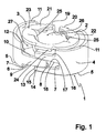
- Fig. 1 shows a perspective view of an embodiment of a device according to the invention designed as a single punched-bent part, which is made of a stamped and bent in the form of sheet metal of relatively precise uniform wall thickness.
- the embodiment according to Fig. 1 has an outer sleeve 1, which has an approximately square flat base wall 2. On one side of the base wall 2, a first side wall 3 bent in a bending direction and a second base wall 4 attached to the side opposite this side, which is also bent in the bending direction on the first side wall 3 to round.
- an inner finger 6 is formed as an element of an engagement structure, which is remote from the base wall 2 facing away from the front edge side 7 of the first side wall 3 in the direction of the opposite end edge side 7 of the second Sidewall 4 extends.
- the inner finger 4 has two of the front-side edge side 7 of the first side wall 3 to one end 8 conically tapered outer sides 9, 10.
- a molding stage 12 is formed, the edge side 7 of the first side wall 3 in which the outer side edge 11 adjacent region opposite to the inner finger 6 adjacent region of the front edge side 7 of the first side wall 3 can recede.
- a first outer finger 13 and a second outer finger 14 are formed at a distance from each other as further elements of the engagement structure, wherein an outer side 15 of the first outer finger 13 is formed flush with the bottom-side outer edge 5 of the second side wall 4 and an outer side 16 of the second outer finger 14 is arranged in a position corresponding to the position of the forming step 12 distance from the outer side edge 11 of the second side wall 4.
- the opposite inner sides 17, 18 of the outer fingers 13, 14 are complementary to the outer sides 9, 10 of the inner finger 6 and thus, starting from the front edge side 7 of the second side wall 4 in the direction of the first side wall 3 a continuously increasing distance, so that at concern the end face 8 of the inner finger 6 at the lying between the outer fingers 13, 14 portion of the front edge side 7 of the second side wall 4, the outer sides 9, 10 of the inner finger 6 at the opposite inner sides 17, 18 of the outer fingers 13, 14 abut flat , Due to the distance between the side facing away from the second side wall 4 free ends of the outer fingers 13, 14, which is greater than the distance between the outer sides 9, 10 of the inner finger 6 in the region of the end face 8, can be due to the thus achieved centering effect, the outer sleeve 1 shut down relatively easily and safely.
- FIG. 1 it is possible Fig. 1 can be seen that the extending between the outer side 16 of the second outer finger 14 and the outer side edge 11 of the second side wall 4 extending portion of the front side edge side 7 of the second side wall 4 opposite to the extending between the outer fingers 13, 14 region of the front edge side 7 of the second side wall 4 is set in the direction of the first side wall 3.
- a first connecting web 19 and a second connecting web 20 are integrally formed on the base wall 2, which are bent from the base wall 2 pioneering by about 90 degrees in the direction of the free ends of the side walls 3, 4.
- a first approximately semicircular ring half 21 is formed, which extends at a radial distance from the outer side edge 8 of the first side wall 3.
- a likewise approximately semicircular second ring half 22 is integrally formed on the second connecting web 20, wherein in this embodiment the ends of the connecting webs 19, 20 remote from the ends in this embodiment a closed cover ring 23 forming ring halves 21, 22 each end with a on the outside 16 of the second outer finger 14 projecting stop pin 24 of a one-piece stop pin arrangement formed here and are interconnected.
- the cover ring 23 is formed very stable.
- each ring half 21, 22 an equal number of locking tongues 25, in this embodiment, in each case a latching tongue 25, which extend in the direction of the bottom outer edges 5 of the ring halves 21, 22 respectively opposite side walls 3, 4, so that starting from one of the ring halves 21, 22 enclosed insertion opening 26 in increasing Distance from the insertion opening 26 in a space enclosed by the outer sleeve 1 receiving space 27 into the distance between the opposing locking tongues 25 is increasingly smaller.
- the ring halves 21, 22 at a distance from the outer side edges 11 of the side walls 3, 4 are arranged.
- the stop pins 24 of the ring halves 21, 22 are even at one of the inner sides 17, 18 of the outer fingers 13, 14 lying portion of the front edge side 7 of the second side wall 4 adjacent end face 8 of the inner finger 6 in the opposite to the outer sides of the deck 11 the side walls 3, 4 recessed outer side 16 of the second outer finger 14 and arranged in the direction of the outer side edge 11 of the first side wall 3 facing surface of the mold stage 12 formed Zapfenabilityaussparung, so that formed by the ring halves 21, 22 cover ring 23 in total in the receiving space 27th can dive, if a corresponding axial pressure force is exerted on an inserted into the insertion opening 26 until engagement with the locking tongues 25 shank of an object.
- the outer side 16 of the second outer finger 14 and possibly also of the mold stage 12 forms a stop for the stop pin 24, which prevents excessive immersion of the cover ring
- Fig. 2 shows in a partially sectioned perspective view of the embodiment according to Fig. 1 in an arrangement in a slot formed in a support member 28 receiving recess 29.
- the inner finger 6 in about to is immersed in the middle of a formed between the outer fingers 13, 14 inner finger receiving space 30, so that still sufficient tolerance for insertion of the fastening device according to the invention in relation to the embodiment according to Fig. 2 smaller dimensioned receiving recesses 29 remains.
- the device according to the invention can also in relation to the embodiment according to Fig.
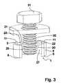
- Fig. 3 shows in a perspective view of the embodiment according to Fig. 1 and Fig. 2 formed with a screw 31 as an object whose externally threaded outer shaft 32 has entered as a shaft into the receiving space 27, in which the screw 31 with its threaded shaft 32 passing through the insertion opening 26 under bearing of the ring halves 21, 22 pioneering free ends the locking tongues 25 has been screwed in at relatively low elasticity in the radial direction or has been inserted in the radial direction at relatively high elasticity.
- the screw 31 is independent of the relative arrangement of the side walls 3, 4 each other captive in the device according to the invention and thus in particular with an open cover ring 23 according to the above-described modification to a in Fig. 3 Not shown receiving part 28, in which the device according to the invention is inserted in a receiving recess 29, held with a certain tolerance with respect to their orientation to the outer sleeve 1 and thus to the receiving part 28.
Landscapes
- Engineering & Computer Science (AREA)
- General Engineering & Computer Science (AREA)
- Mechanical Engineering (AREA)
- Snaps, Bayonet Connections, Set Pins, And Snap Rings (AREA)
Claims (10)
- Dispositif pour le maintien imperdable d'une tige (32) d'un objet (31) sur une pièce de réception (28), comprenant une douille extérieure (1) qui est destinée à être emmanchée dans un évidement de réception (29) ménagé dans la pièce de réception (28) et qui définit un espace de réception (27) et comprenant un certain nombre de languettes d'accrochage (25) qui font saillie dans l'espace de réception (27), qui sont configurées pour venir en prise d'encastrement avec la tige (32), le dispositif se présentant en l'occurrence sous la forme d'une pièce monobloc obtenue par découpage à la presse et pliage, qui est réalisée à partir d'un flan en tôle découpé à la presse et mis en forme par pliage, caractérisé en ce que la douille extérieure (1) se compose d'une paroi de base (2) et de deux parois latérales (3, 4) disposées de part et d'autre de la paroi de base (2), dont les bords latéraux antérieurs (7), orientés à l'opposé de la paroi de base (2), se font respectivement face, en ce qu'une bague d'entretoisement (23) définissant une ouverture d'introduction (26) dans l'espace de réception (27) est raccordée à la douille extérieure (1) par l'intermédiaire d'au moins une barrette entretoise de liaison (19, 20) et en ce que les languettes d'accrochage (25) sont disposées attenantes à la bague d'entretoisement (23).
- Dispositif selon la revendication 1, caractérisé en ce que les bords latéraux antérieurs (7) des parois latérales (3, 4) sont munis d'une structure de mise en prise d'encastrement (6, 13, 14).
- Dispositif selon la revendication 2, caractérisé en ce que la structure de mise en prise d'encastrement se compose de deux doigts extérieurs (13, 14) disposés attenants à un bord latéral antérieur (7) et d'un doigt intérieur central (6) disposé attenant à l'autre bord latéral antérieur (7) qui, lorsque le dispositif est disposé dans sa position d'utilisation dans un évidement de réception (29), vient s'insérer dans un espace d'emmanchement de doigt intérieur (30) prévu entre les doigts extérieurs (13, 14).
- Dispositif selon la revendication 3, caractérisé en ce que le doigt intérieur (6) va en s'amenuisant vers l'extérieur, depuis le bord latéral antérieur (7) auquel il est attenant, suivant un tracé conique et en ce que la configuration de l'espace d'emmanchement du doigt intérieur (30)est étudiée pour venir en correspondance d'accouplement avec celle du doigt intérieur (6).
- Dispositif selon l'une des revendications 1 à 4, caractérisé en ce que la bague d'entretoisement (23) est munie d'un agencement formant collet de butée (24) qui est disposé à l'opposé de la ou de chaque barrette entretoise de liaison (19, 20) et qui fait saillie dans le plan radial au-dessus de l'espace de réception (27).
- Dispositif selon la revendication 5, caractérisé en ce que la douille extérieure (1) est pourvue, dans la zone de l'agencement formant collet de butée (24), d'une échancrure de réception du collet.
- Dispositif selon l'une des revendications 1 à 6, caractérisé en ce que la bague d'entretoisement (23) est raccordée à la douille extérieure (1) par l'intermédiaire de deux barrettes entretoises de liaison (29, 20) attenantes à la paroi de base (2).
- Dispositif selon l'une des revendications 1 à 7, caractérisé en ce que la bague d'entretoisement (23) est de type monobloc.
- Dispositif selon l'une des revendications 1 à 7, caractérisé en ce que la bague d'entretoisement (23) se compose de deux moitiés annulaires (21, 22), dont les extrémités libres sont disposées opposées à la ou à chaque barrette entretoise de liaison (19, 20) et sont très voisines l'une de l'autre ou contigües l'une à l'autre.
- Dispositif selon la revendication 9, caractérisé en ce que chaque moitié annulaire (21, 22) comporte un même nombre de languettes d'accrochage (25).
Applications Claiming Priority (2)
| Application Number | Priority Date | Filing Date | Title |
|---|---|---|---|
| DE200810026768 DE102008026768A1 (de) | 2008-06-04 | 2008-06-04 | Vorrichtung zum verliersicheren Halten eines Schaftes eines Gegenstandes an einem Aufnahmeteil |
| PCT/EP2009/003380 WO2009146778A1 (fr) | 2008-06-04 | 2009-05-13 | Dispositif pour le maintien imperdable d’une tige d’un objet sur une pièce de réception |
Publications (2)
| Publication Number | Publication Date |
|---|---|
| EP2297472A1 EP2297472A1 (fr) | 2011-03-23 |
| EP2297472B1 true EP2297472B1 (fr) | 2013-07-10 |
Family
ID=41010443
Family Applications (1)
| Application Number | Title | Priority Date | Filing Date |
|---|---|---|---|
| EP09757162.4A Not-in-force EP2297472B1 (fr) | 2008-06-04 | 2009-05-13 | Dispositif pour le maintien imperdable d une tige d un objet sur une pièce de réception |
Country Status (3)
| Country | Link |
|---|---|
| EP (1) | EP2297472B1 (fr) |
| DE (1) | DE102008026768A1 (fr) |
| WO (1) | WO2009146778A1 (fr) |
Family Cites Families (4)
| Publication number | Priority date | Publication date | Assignee | Title |
|---|---|---|---|---|
| US3645311A (en) * | 1965-09-20 | 1972-02-29 | George A Tinnerman | Constant torque threaded fastener formation |
| US5074727A (en) | 1990-10-26 | 1991-12-24 | At&T Bell Laboratories | Threaded device retainer |
| DE19523932C2 (de) * | 1994-07-21 | 1997-02-20 | Kostal Leopold Gmbh & Co Kg | Verliersicherung für in Bauteile lose eingesetzte Schrauben |
| DE19524932A1 (de) | 1995-07-08 | 1997-01-09 | Werner Bracht | Großanzeigesystem zur Darstellung der Wettkampfdaten bei Mannschaftssportarten |
-
2008
- 2008-06-04 DE DE200810026768 patent/DE102008026768A1/de not_active Ceased
-
2009
- 2009-05-13 EP EP09757162.4A patent/EP2297472B1/fr not_active Not-in-force
- 2009-05-13 WO PCT/EP2009/003380 patent/WO2009146778A1/fr not_active Ceased
Also Published As
| Publication number | Publication date |
|---|---|
| EP2297472A1 (fr) | 2011-03-23 |
| WO2009146778A1 (fr) | 2009-12-10 |
| DE102008026768A1 (de) | 2009-12-17 |
Similar Documents
| Publication | Publication Date | Title |
|---|---|---|
| EP1977121B1 (fr) | Ecrou male | |
| EP2670988B1 (fr) | Dispositif de fixation | |
| EP2301115B1 (fr) | Dispositif de connexion électrique | |
| EP1697644B1 (fr) | Dispositif de connexion d'une piece support et d'une piece rapportee | |
| DE19835020A1 (de) | Buchsenkontakt | |
| EP3058624B1 (fr) | Connecteur doté d'un système d'encliquetage | |
| DE102016118640B4 (de) | Federelement | |
| EP3396786A1 (fr) | Dispositif de connecteur | |
| EP3687002A1 (fr) | Ressort de serrage et borne de raccordement de conducteur | |
| EP3954905B1 (fr) | Élément ressort | |
| EP1655813A1 (fr) | Fixation pour connexion électrique | |
| DE112012003463T5 (de) | Verbinder | |
| EP3884197B1 (fr) | Accouplement | |
| DE102014224932A1 (de) | Haltevorrichtung für eine Schraubenmutter sowie Baueinheit mit einer solchen Haltevorrichtung | |
| EP1963689B1 (fr) | Ecrou en plaque de metal | |
| WO2017198728A1 (fr) | Dispositif de contact pour la transmission d'énergie électrique à une plaque conductrice et procédé de montage d'un tel dispositif de contact | |
| EP2598761B1 (fr) | Dispositif à monter sur un axe fileté | |
| DE102007015129B3 (de) | Nicht demontierbarer Clip aus Kunststoff | |
| EP1587172B1 (fr) | Douille pour connection électrique avec une fiche plus particulièrement une fiche plate | |
| EP2297472B1 (fr) | Dispositif pour le maintien imperdable d une tige d un objet sur une pièce de réception | |
| EP2281122B1 (fr) | Pince de fixation et dispositif présentant une pince de fixation et un composant associé | |
| DE20120266U1 (de) | Gleitlagerkörper und Gleitlager mit Gleitlagerkörper | |
| EP1978195B1 (fr) | Armature enfichable | |
| DE112012003699T5 (de) | Steckverbinder | |
| DE3500975C2 (fr) |
Legal Events
| Date | Code | Title | Description |
|---|---|---|---|
| PUAI | Public reference made under article 153(3) epc to a published international application that has entered the european phase |
Free format text: ORIGINAL CODE: 0009012 |
|
| 17P | Request for examination filed |
Effective date: 20110104 |
|
| AK | Designated contracting states |
Kind code of ref document: A1 Designated state(s): AT BE BG CH CY CZ DE DK EE ES FI FR GB GR HR HU IE IS IT LI LT LU LV MC MK MT NL NO PL PT RO SE SI SK TR |
|
| AX | Request for extension of the european patent |
Extension state: AL BA RS |
|
| DAX | Request for extension of the european patent (deleted) | ||
| GRAP | Despatch of communication of intention to grant a patent |
Free format text: ORIGINAL CODE: EPIDOSNIGR1 |
|
| GRAS | Grant fee paid |
Free format text: ORIGINAL CODE: EPIDOSNIGR3 |
|
| GRAA | (expected) grant |
Free format text: ORIGINAL CODE: 0009210 |
|
| AK | Designated contracting states |
Kind code of ref document: B1 Designated state(s): AT BE BG CH CY CZ DE DK EE ES FI FR GB GR HR HU IE IS IT LI LT LU LV MC MK MT NL NO PL PT RO SE SI SK TR |
|
| REG | Reference to a national code |
Ref country code: GB Ref legal event code: FG4D Free format text: NOT ENGLISH |
|
| REG | Reference to a national code |
Ref country code: AT Ref legal event code: REF Ref document number: 621144 Country of ref document: AT Kind code of ref document: T Effective date: 20130715 Ref country code: CH Ref legal event code: EP |
|
| REG | Reference to a national code |
Ref country code: IE Ref legal event code: FG4D Free format text: LANGUAGE OF EP DOCUMENT: GERMAN |
|
| REG | Reference to a national code |
Ref country code: DE Ref legal event code: R096 Ref document number: 502009007551 Country of ref document: DE Effective date: 20130905 |
|
| PG25 | Lapsed in a contracting state [announced via postgrant information from national office to epo] |
Ref country code: SI Free format text: LAPSE BECAUSE OF FAILURE TO SUBMIT A TRANSLATION OF THE DESCRIPTION OR TO PAY THE FEE WITHIN THE PRESCRIBED TIME-LIMIT Effective date: 20130710 |
|
| REG | Reference to a national code |
Ref country code: NL Ref legal event code: VDEP Effective date: 20130710 |
|
| REG | Reference to a national code |
Ref country code: LT Ref legal event code: MG4D |
|
| PG25 | Lapsed in a contracting state [announced via postgrant information from national office to epo] |
Ref country code: PT Free format text: LAPSE BECAUSE OF FAILURE TO SUBMIT A TRANSLATION OF THE DESCRIPTION OR TO PAY THE FEE WITHIN THE PRESCRIBED TIME-LIMIT Effective date: 20131111 Ref country code: HR Free format text: LAPSE BECAUSE OF FAILURE TO SUBMIT A TRANSLATION OF THE DESCRIPTION OR TO PAY THE FEE WITHIN THE PRESCRIBED TIME-LIMIT Effective date: 20130710 Ref country code: LT Free format text: LAPSE BECAUSE OF FAILURE TO SUBMIT A TRANSLATION OF THE DESCRIPTION OR TO PAY THE FEE WITHIN THE PRESCRIBED TIME-LIMIT Effective date: 20130710 Ref country code: CY Free format text: LAPSE BECAUSE OF FAILURE TO SUBMIT A TRANSLATION OF THE DESCRIPTION OR TO PAY THE FEE WITHIN THE PRESCRIBED TIME-LIMIT Effective date: 20130710 Ref country code: IS Free format text: LAPSE BECAUSE OF FAILURE TO SUBMIT A TRANSLATION OF THE DESCRIPTION OR TO PAY THE FEE WITHIN THE PRESCRIBED TIME-LIMIT Effective date: 20131110 Ref country code: SE Free format text: LAPSE BECAUSE OF FAILURE TO SUBMIT A TRANSLATION OF THE DESCRIPTION OR TO PAY THE FEE WITHIN THE PRESCRIBED TIME-LIMIT Effective date: 20130710 Ref country code: NO Free format text: LAPSE BECAUSE OF FAILURE TO SUBMIT A TRANSLATION OF THE DESCRIPTION OR TO PAY THE FEE WITHIN THE PRESCRIBED TIME-LIMIT Effective date: 20131010 |
|
| PG25 | Lapsed in a contracting state [announced via postgrant information from national office to epo] |
Ref country code: ES Free format text: LAPSE BECAUSE OF FAILURE TO SUBMIT A TRANSLATION OF THE DESCRIPTION OR TO PAY THE FEE WITHIN THE PRESCRIBED TIME-LIMIT Effective date: 20131021 Ref country code: PL Free format text: LAPSE BECAUSE OF FAILURE TO SUBMIT A TRANSLATION OF THE DESCRIPTION OR TO PAY THE FEE WITHIN THE PRESCRIBED TIME-LIMIT Effective date: 20130710 Ref country code: GR Free format text: LAPSE BECAUSE OF FAILURE TO SUBMIT A TRANSLATION OF THE DESCRIPTION OR TO PAY THE FEE WITHIN THE PRESCRIBED TIME-LIMIT Effective date: 20131011 Ref country code: NL Free format text: LAPSE BECAUSE OF FAILURE TO SUBMIT A TRANSLATION OF THE DESCRIPTION OR TO PAY THE FEE WITHIN THE PRESCRIBED TIME-LIMIT Effective date: 20130710 Ref country code: FI Free format text: LAPSE BECAUSE OF FAILURE TO SUBMIT A TRANSLATION OF THE DESCRIPTION OR TO PAY THE FEE WITHIN THE PRESCRIBED TIME-LIMIT Effective date: 20130710 Ref country code: LV Free format text: LAPSE BECAUSE OF FAILURE TO SUBMIT A TRANSLATION OF THE DESCRIPTION OR TO PAY THE FEE WITHIN THE PRESCRIBED TIME-LIMIT Effective date: 20130710 |
|
| PG25 | Lapsed in a contracting state [announced via postgrant information from national office to epo] |
Ref country code: RO Free format text: LAPSE BECAUSE OF FAILURE TO SUBMIT A TRANSLATION OF THE DESCRIPTION OR TO PAY THE FEE WITHIN THE PRESCRIBED TIME-LIMIT Effective date: 20130710 Ref country code: SK Free format text: LAPSE BECAUSE OF FAILURE TO SUBMIT A TRANSLATION OF THE DESCRIPTION OR TO PAY THE FEE WITHIN THE PRESCRIBED TIME-LIMIT Effective date: 20130710 Ref country code: DK Free format text: LAPSE BECAUSE OF FAILURE TO SUBMIT A TRANSLATION OF THE DESCRIPTION OR TO PAY THE FEE WITHIN THE PRESCRIBED TIME-LIMIT Effective date: 20130710 Ref country code: EE Free format text: LAPSE BECAUSE OF FAILURE TO SUBMIT A TRANSLATION OF THE DESCRIPTION OR TO PAY THE FEE WITHIN THE PRESCRIBED TIME-LIMIT Effective date: 20130710 Ref country code: CZ Free format text: LAPSE BECAUSE OF FAILURE TO SUBMIT A TRANSLATION OF THE DESCRIPTION OR TO PAY THE FEE WITHIN THE PRESCRIBED TIME-LIMIT Effective date: 20130710 |
|
| PLBE | No opposition filed within time limit |
Free format text: ORIGINAL CODE: 0009261 |
|
| STAA | Information on the status of an ep patent application or granted ep patent |
Free format text: STATUS: NO OPPOSITION FILED WITHIN TIME LIMIT |
|
| PG25 | Lapsed in a contracting state [announced via postgrant information from national office to epo] |
Ref country code: IT Free format text: LAPSE BECAUSE OF FAILURE TO SUBMIT A TRANSLATION OF THE DESCRIPTION OR TO PAY THE FEE WITHIN THE PRESCRIBED TIME-LIMIT Effective date: 20130710 |
|
| 26N | No opposition filed |
Effective date: 20140411 |
|
| REG | Reference to a national code |
Ref country code: DE Ref legal event code: R082 Ref document number: 502009007551 Country of ref document: DE |
|
| REG | Reference to a national code |
Ref country code: DE Ref legal event code: R097 Ref document number: 502009007551 Country of ref document: DE Effective date: 20140411 |
|
| PG25 | Lapsed in a contracting state [announced via postgrant information from national office to epo] |
Ref country code: LU Free format text: LAPSE BECAUSE OF FAILURE TO SUBMIT A TRANSLATION OF THE DESCRIPTION OR TO PAY THE FEE WITHIN THE PRESCRIBED TIME-LIMIT Effective date: 20140513 |
|
| REG | Reference to a national code |
Ref country code: CH Ref legal event code: PL |
|
| GBPC | Gb: european patent ceased through non-payment of renewal fee |
Effective date: 20140513 |
|
| PG25 | Lapsed in a contracting state [announced via postgrant information from national office to epo] |
Ref country code: CH Free format text: LAPSE BECAUSE OF NON-PAYMENT OF DUE FEES Effective date: 20140531 Ref country code: MC Free format text: LAPSE BECAUSE OF FAILURE TO SUBMIT A TRANSLATION OF THE DESCRIPTION OR TO PAY THE FEE WITHIN THE PRESCRIBED TIME-LIMIT Effective date: 20130710 Ref country code: LI Free format text: LAPSE BECAUSE OF NON-PAYMENT OF DUE FEES Effective date: 20140531 |
|
| REG | Reference to a national code |
Ref country code: IE Ref legal event code: MM4A |
|
| PG25 | Lapsed in a contracting state [announced via postgrant information from national office to epo] |
Ref country code: IE Free format text: LAPSE BECAUSE OF NON-PAYMENT OF DUE FEES Effective date: 20140513 |
|
| PG25 | Lapsed in a contracting state [announced via postgrant information from national office to epo] |
Ref country code: GB Free format text: LAPSE BECAUSE OF NON-PAYMENT OF DUE FEES Effective date: 20140513 |
|
| REG | Reference to a national code |
Ref country code: AT Ref legal event code: MM01 Ref document number: 621144 Country of ref document: AT Kind code of ref document: T Effective date: 20140513 |
|
| PG25 | Lapsed in a contracting state [announced via postgrant information from national office to epo] |
Ref country code: AT Free format text: LAPSE BECAUSE OF NON-PAYMENT OF DUE FEES Effective date: 20140513 |
|
| PG25 | Lapsed in a contracting state [announced via postgrant information from national office to epo] |
Ref country code: MT Free format text: LAPSE BECAUSE OF FAILURE TO SUBMIT A TRANSLATION OF THE DESCRIPTION OR TO PAY THE FEE WITHIN THE PRESCRIBED TIME-LIMIT Effective date: 20130710 |
|
| REG | Reference to a national code |
Ref country code: FR Ref legal event code: PLFP Year of fee payment: 8 |
|
| PG25 | Lapsed in a contracting state [announced via postgrant information from national office to epo] |
Ref country code: BG Free format text: LAPSE BECAUSE OF FAILURE TO SUBMIT A TRANSLATION OF THE DESCRIPTION OR TO PAY THE FEE WITHIN THE PRESCRIBED TIME-LIMIT Effective date: 20130710 |
|
| PG25 | Lapsed in a contracting state [announced via postgrant information from national office to epo] |
Ref country code: TR Free format text: LAPSE BECAUSE OF FAILURE TO SUBMIT A TRANSLATION OF THE DESCRIPTION OR TO PAY THE FEE WITHIN THE PRESCRIBED TIME-LIMIT Effective date: 20130710 Ref country code: HU Free format text: LAPSE BECAUSE OF FAILURE TO SUBMIT A TRANSLATION OF THE DESCRIPTION OR TO PAY THE FEE WITHIN THE PRESCRIBED TIME-LIMIT; INVALID AB INITIO Effective date: 20090513 Ref country code: BE Free format text: LAPSE BECAUSE OF FAILURE TO SUBMIT A TRANSLATION OF THE DESCRIPTION OR TO PAY THE FEE WITHIN THE PRESCRIBED TIME-LIMIT Effective date: 20140531 |
|
| REG | Reference to a national code |
Ref country code: FR Ref legal event code: PLFP Year of fee payment: 9 |
|
| REG | Reference to a national code |
Ref country code: FR Ref legal event code: PLFP Year of fee payment: 10 |
|
| PG25 | Lapsed in a contracting state [announced via postgrant information from national office to epo] |
Ref country code: MK Free format text: LAPSE BECAUSE OF FAILURE TO SUBMIT A TRANSLATION OF THE DESCRIPTION OR TO PAY THE FEE WITHIN THE PRESCRIBED TIME-LIMIT Effective date: 20130710 |
|
| PGFP | Annual fee paid to national office [announced via postgrant information from national office to epo] |
Ref country code: DE Payment date: 20190521 Year of fee payment: 11 |
|
| PGFP | Annual fee paid to national office [announced via postgrant information from national office to epo] |
Ref country code: FR Payment date: 20190523 Year of fee payment: 11 |
|
| REG | Reference to a national code |
Ref country code: DE Ref legal event code: R119 Ref document number: 502009007551 Country of ref document: DE |
|
| PG25 | Lapsed in a contracting state [announced via postgrant information from national office to epo] |
Ref country code: FR Free format text: LAPSE BECAUSE OF NON-PAYMENT OF DUE FEES Effective date: 20200531 |
|
| PG25 | Lapsed in a contracting state [announced via postgrant information from national office to epo] |
Ref country code: DE Free format text: LAPSE BECAUSE OF NON-PAYMENT OF DUE FEES Effective date: 20201201 |