EP2296437A1 - Light adjustment circuit for alternating-current - Google Patents
Light adjustment circuit for alternating-current Download PDFInfo
- Publication number
- EP2296437A1 EP2296437A1 EP20090177447 EP09177447A EP2296437A1 EP 2296437 A1 EP2296437 A1 EP 2296437A1 EP 20090177447 EP20090177447 EP 20090177447 EP 09177447 A EP09177447 A EP 09177447A EP 2296437 A1 EP2296437 A1 EP 2296437A1
- Authority
- EP
- European Patent Office
- Prior art keywords
- led
- light adjustment
- circuit
- signal
- power
- Prior art date
- Legal status (The legal status is an assumption and is not a legal conclusion. Google has not performed a legal analysis and makes no representation as to the accuracy of the status listed.)
- Ceased
Links
- 238000010586 diagram Methods 0.000 description 15
- 239000003990 capacitor Substances 0.000 description 3
- 239000006096 absorbing agent Substances 0.000 description 1
- 238000006243 chemical reaction Methods 0.000 description 1
- 230000007423 decrease Effects 0.000 description 1
- 230000003247 decreasing effect Effects 0.000 description 1
- 238000001514 detection method Methods 0.000 description 1
- 230000005693 optoelectronics Effects 0.000 description 1
Images




Classifications
-
- H—ELECTRICITY
- H02—GENERATION; CONVERSION OR DISTRIBUTION OF ELECTRIC POWER
- H02M—APPARATUS FOR CONVERSION BETWEEN AC AND AC, BETWEEN AC AND DC, OR BETWEEN DC AND DC, AND FOR USE WITH MAINS OR SIMILAR POWER SUPPLY SYSTEMS; CONVERSION OF DC OR AC INPUT POWER INTO SURGE OUTPUT POWER; CONTROL OR REGULATION THEREOF
- H02M5/00—Conversion of AC power input into AC power output, e.g. for change of voltage, for change of frequency, for change of number of phases
- H02M5/02—Conversion of AC power input into AC power output, e.g. for change of voltage, for change of frequency, for change of number of phases without intermediate conversion into DC
- H02M5/04—Conversion of AC power input into AC power output, e.g. for change of voltage, for change of frequency, for change of number of phases without intermediate conversion into DC by static converters
- H02M5/22—Conversion of AC power input into AC power output, e.g. for change of voltage, for change of frequency, for change of number of phases without intermediate conversion into DC by static converters using discharge tubes with control electrode or semiconductor devices with control electrode
- H02M5/275—Conversion of AC power input into AC power output, e.g. for change of voltage, for change of frequency, for change of number of phases without intermediate conversion into DC by static converters using discharge tubes with control electrode or semiconductor devices with control electrode using devices of a triode or transistor type requiring continuous application of a control signal
- H02M5/293—Conversion of AC power input into AC power output, e.g. for change of voltage, for change of frequency, for change of number of phases without intermediate conversion into DC by static converters using discharge tubes with control electrode or semiconductor devices with control electrode using devices of a triode or transistor type requiring continuous application of a control signal using semiconductor devices only
-
- H—ELECTRICITY
- H05—ELECTRIC TECHNIQUES NOT OTHERWISE PROVIDED FOR
- H05B—ELECTRIC HEATING; ELECTRIC LIGHT SOURCES NOT OTHERWISE PROVIDED FOR; CIRCUIT ARRANGEMENTS FOR ELECTRIC LIGHT SOURCES, IN GENERAL
- H05B45/00—Circuit arrangements for operating light-emitting diodes [LED]
- H05B45/30—Driver circuits
- H05B45/32—Pulse-control circuits
-
- H—ELECTRICITY
- H05—ELECTRIC TECHNIQUES NOT OTHERWISE PROVIDED FOR
- H05B—ELECTRIC HEATING; ELECTRIC LIGHT SOURCES NOT OTHERWISE PROVIDED FOR; CIRCUIT ARRANGEMENTS FOR ELECTRIC LIGHT SOURCES, IN GENERAL
- H05B45/00—Circuit arrangements for operating light-emitting diodes [LED]
- H05B45/30—Driver circuits
- H05B45/37—Converter circuits
- H05B45/3725—Switched mode power supply [SMPS]
-
- Y—GENERAL TAGGING OF NEW TECHNOLOGICAL DEVELOPMENTS; GENERAL TAGGING OF CROSS-SECTIONAL TECHNOLOGIES SPANNING OVER SEVERAL SECTIONS OF THE IPC; TECHNICAL SUBJECTS COVERED BY FORMER USPC CROSS-REFERENCE ART COLLECTIONS [XRACs] AND DIGESTS
- Y02—TECHNOLOGIES OR APPLICATIONS FOR MITIGATION OR ADAPTATION AGAINST CLIMATE CHANGE
- Y02B—CLIMATE CHANGE MITIGATION TECHNOLOGIES RELATED TO BUILDINGS, e.g. HOUSING, HOUSE APPLIANCES OR RELATED END-USER APPLICATIONS
- Y02B20/00—Energy efficient lighting technologies, e.g. halogen lamps or gas discharge lamps
- Y02B20/30—Semiconductor lamps, e.g. solid state lamps [SSL] light emitting diodes [LED] or organic LED [OLED]
Definitions
- This disclosure generally relates to a light adjustment circuit for alternating-current light emitting diodes (AC-LED's) and, more particularly, to a light adjustment circuit capable of adjusting the brightness of AC-LED's in correspondence to variation in input AC power to enable each of the AC-LED's to achieve a predetermined brightness with enhanced reliability and lifetime.
- AC-LED's alternating-current light emitting diodes
- alternating-current light emitting diodes are novel and promising because they are directly driven by an AC power supply with higher efficiency and reliability than conventional DC-LED's.
- a current-limiting resistor is serially connected so as to limit the current from the AC power supply and protect the AC-LED's from being burnt out.
- a current-limiting resistor is only capable of limiting over-current and is unable to overcome the problems, such as affected output characteristics, due to variations in voltage and frequency of the AC power supply.
- the current-limiting resistor causes power loss that lowers the power conversion rate and is unable to achieve light adjustment circuit for the AC-LED's.
- U.S. Pat. Pub. No. 2004/0206970 discloses an LED driving circuit as shown in FIG 1 .
- the LED driving circuit comprises a full-bridge rectifier 12 and an output filter capacitor 13 so as to rectify the AC power from an AC power supply 11 and provide a load (such as an LED) 14 with stable DC power.
- the output filter capacitor 13 filters the rectified voltage to provide stable DC power supply to the LED 14 even though the input AC power may be unstable.
- the driving circuit provides DC power to the load, the DC power may be insufficient for AC-LED's as the load to cause lowered brightness. Meanwhile, the driving circuit is unable to achieve light adjustment circuit for the AC-LED's and to turn off the AC-LED's when the input voltage is too high.
- U.S. Pat. No. 7,489,086 discloses an LED driving circuit as shown in FIG. 2 .
- the LED driving circuit comprises a fixed high-frequency inverter 22 capable of converting the power from the input AC voltage or DC voltage 21 and providing a relatively constant voltage and relatively constant frequency output 24 to be delivered to a load (such an AC-LED).
- the ED driving circuit further comprises an AC regulator 23 that senses changes to the load at the output lines of the inverter 22 and feeds back a voltage signal to the inverter 22 in response to changes in the load which makes adjustments accordingly to maintain a relatively constant voltage output with the relatively constant frequency output.
- the LED driving circuit is complicated with high cost and is unable to turn off the AC-LED when the input voltage is too high.
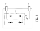
- TW Pat. Appl. No. 095146805 discloses an LED driving circuit as shown in FIG. 3 .
- an AC-LED array 31 disposed between two terminals 33 and 34 is connected in series or in parallel with an element 32 being a resistor, a capacitor, a Zener diode or a surge absorber so that the LED driving circuit provides temperature compensation, voltage correction or surge protection.
- phase control has been reported using a zero voltage detection circuit to achieve light adjustment for AC-LED's. However, it fails to turn off the AC-LED's when the input voltage is too high.
- This disclosure provides a light adjustment circuit for AC-LED's, capable of adjusting the brightness of AC-LED's in correspondence to variation in input AC power to enable each of the AC-LED's to achieve a predetermined brightness with enhanced reliability and lifetime.
- this disclosure discloses a light adjustment circuit for AC-LED's, capable of adjusting the brightness of AC-LED's in correspondence to variation in input AC power to enable each of the AC-LED's to achieve a predetermined brightness with enhanced reliability and lifetime.
- this disclosure provides a light adjustment circuit for alternating-current light emitting diodes (AC-LED's), the light adjustment circuit being connected to an AC power supply and a plurality of AC-LED's, the light adjustment circuit comprising:
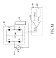
- FIG. 4A is a circuit diagram of a light adjustment circuit for AC-LED's according to a first embodiment of this disclosure.
- the light adjustment circuit comprises an light adjustment unit 42 (composed of diodes D1, D2, D3, D4 and a control switch S1) and pulse width modulation (PWM) control circuit 43 to adjust the brightness of AC-LED's 44 in correspondence to variation in input AC power from an AC power supply 41 to enable each of the AC-LED's 44 to achieve a predetermined brightness.
- An external voltage signal Vext is compared with a triangle wave or a sawtooth wave from a ramp generator 432 to obtain light adjustment signals with different duty cycles.
- the light adjustment signal is then transmitted to the control switch S1 to control the power delivered to the AC-LED's.
- the control switch determines the value of the current delivered to the AC-LED's according to the duty cycle. Therefore, as the duty cycle of the control switch S1 increases, the control switch S1 allows larger power to be delivered to the AC-LED's to improve the AC-LED brightness. On the contrary, as the duty cycle of the control switch S1 decreases, the control switch S1 allows smaller power to be delivered to the AC-LED's to lower the AC-LED brightness.
- the control switch S1 is disposed between the four diodes D1, D2, D3, D4 so that the light adjustment circuit is capable of achieving light adjustment during both positive half cycle and negative half cycle.
- the PWM control circuit 43 can be analog and comprise a ramp generator 432 and a comparator 431.
- the ramp generator 432 is capable of generating a triangle wave or a sawtooth wave.
- the comparator 431 has a negative input terminal receiving the external voltage signal Vext and a positive input terminal connected to the ramp generator 432, so that the comparator 431 performs voltage comparison on an input ramp signal at the positive input terminal and the external voltage signal Vext at the negative input terminal so as to output a pulse width modulation (PWM) signal at an output terminal of the comparator 431.
- PWM pulse width modulation
- the PWM control circuit 43 can also be digital and comprise a digital controller.
- the digital controller is capable of receiving an external voltage signal Vext that is to be processed by the digital controller to output a PWM signal.
- the external voltage signal Vext can be used to adjust the brightness according to variation in input AC power and the requirements of the user.
- FIG. 5 is a waveform diagram for light adjustment using the light adjustment circuit in FIG. 4A .
- the waveform diagram represents an input power signal 51, an AC-LED current signal 52 and a PWM signal 53.
- the input power signal (from the AC utility) 51 rises, the AC-LED current signal 52 rises.
- the duty cycle of the PWM signal 53 can be lowered by modulating the external voltage signal Vext to lower the power (in terms of current) delivered to the AC-LED's. Therefore, the current signal 52 of the AC-LED's is decreased to achieve a predetermined brightness.
- the AC-LED current signal 52 falls.
- the duty cycle of the PWM signal 53 can be increased by modulating the external voltage signal Vext to increase the power delivered to the AC-LED's. Therefore, the current signal 52 of the AC-LED's is increased to achieve a predetermined brightness. When the temperature of the AC-LED's is too high, the external voltage signal Vext can be adjusted to lower the duty cycle to zero. Meanwhile, the control switch S 1 is completely turned off to protect the AC-LED's.
- the external voltage signal Vext can be coupled to a voltage feedback circuit, a current feedback circuit, a temperature feedback circuit or an external light adjustment signal.
- the external voltage signal Vext can be coupled to a voltage feedback circuit to detect the input AC power or a voltage cross the AC-LED's to monitor the AC-LED's.
- the external voltage signal Vext can be coupled to a current feedback circuit to detect the input AC power or a current flowing through the AC-LED's to monitor the AC-LED's.
- the external voltage signal Vext can be coupled to a temperature feedback circuit comprising a temperature detector and a signal transformer.
- the temperature detector is attached to the AC-LED's to obtain a temperature value transformed to the temperature feedback signal by the signal transformer so as to provide the PWM control circuit with the temperature feedback signal whose duty cycle is to be adjusted by the PWM control circuit.
- the external light adjustment signal can be analog or digital to adjust the brightness of the AC-LED's.
- FIG. 4B , FIG. 4C , FIG. 4D and FIG. 4E for a circuit diagram of a light adjustment circuit for AC-LED's according to a second, a third, a fourth and a fifth embodiments of this disclosure.
- the external voltage signal Vext is coupled to a current feedback circuit.
- the current feedback circuit comprises a current detector 45 receiving a current feedback signal 451.
- the current detector 45 is connected in series with the AC-LED's 44 to obtain the value of the AC-LED current whose duty cycle is to be adjusted by the PWM control circuit 43.
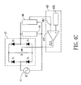
- the external voltage signal Vext is coupled to a voltage feedback circuit.
- the voltage feedback circuit comprises a voltage detector 46 receiving a voltage feedback signal 461.
- the voltage detector 46 is connected in parallel with the AC-LED's 44 to obtain the value of the AC-LED voltage whose duty cycle is to be adjusted by the PWM control circuit 43.
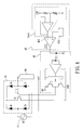
- the external voltage signal Vext is coupled to a temperature feedback circuit.
- the temperature feedback circuit comprises a temperature detector 47 and a signal transformer 471.
- the temperature detector 47 is attached to the AC-LED's 44 to obtain a temperature value transformed to a temperature feedback signal 472 by the signal transformer 471 so as to provide the PWM control circuit 43 with the temperature feedback signal 472 whose duty cycle is to be adjusted by the PWM control circuit 43.
- the external voltage signal Vext is coupled to an analog or a digital transformer 48 receiving an external analog or a digital light adjustment signal 481 to be transformed to an adjusted signal 482 whose duty cycle is to be adjusted by the PWM control circuit 43.
- FIG. 6 is a detailed circuit of the circuit diagram of FIG. 4A .
- a comparator 431 performs a comparison on an external voltage signal Vext sampled by an operational amplifier and a sawtooth wave to obtain signals with different duty cycles.
- a light isolator 49 transmits the signals to the control switch S1 in the light adjustment unit 42 to control the turn-on time of the control switch S1 to complete light adjustment for the AC-LED's.
- the light isolator 49 is disposed between the light adjustment unit 42 and the PWM control circuit 43.
- FIG 7 and FIG. 8 show the waveform of voltage and current when the input voltage is 110 and 120 Vrms, respectively.
- the illuminance is 1205 Lux.
- the illuminance increases up to 1730 Lux.
- the duty cycle falls from 100% to 64% to keep the illuminance at 1205 Lux. Therefore, the light adjustment circuit of this disclosure can be experimentally demonstrated by adjusting the duty cycle of the PWM signal of the control switch to achieve light adjustment for the AC-LED's.
- This disclosure discloses a light adjustment circuit capable of adjusting the brightness of AC-LED's in correspondence to variation in input AC power to enable each of the AC-LED's to achieve a predetermined brightness with enhanced reliability and lifetime. Therefore, this disclosure is useful, novel and non-obvious.
Landscapes
- Engineering & Computer Science (AREA)
- Power Engineering (AREA)
- Circuit Arrangement For Electric Light Sources In General (AREA)
- Led Devices (AREA)
Abstract
Description
- This disclosure generally relates to a light adjustment circuit for alternating-current light emitting diodes (AC-LED's) and, more particularly, to a light adjustment circuit capable of adjusting the brightness of AC-LED's in correspondence to variation in input AC power to enable each of the AC-LED's to achieve a predetermined brightness with enhanced reliability and lifetime.
- Unlike conventional direct-current light emitting diodes (DC-LED's) that require an AC-to-DC power supply, alternating-current light emitting diodes (AC-LED's) are novel and promising because they are directly driven by an AC power supply with higher efficiency and reliability than conventional DC-LED's.
- However, variations in voltage and frequency of the input AC power supply affect the opto-electronics characteristics of the AC-LED's to cause unstable brightness of the AC-LED's since the AC-LED's are directly coupled to the AC power supply.
- In view of the above, it is generally that a current-limiting resistor is serially connected so as to limit the current from the AC power supply and protect the AC-LED's from being burnt out. However, such a current-limiting resistor is only capable of limiting over-current and is unable to overcome the problems, such as affected output characteristics, due to variations in voltage and frequency of the AC power supply. Moreover, the current-limiting resistor causes power loss that lowers the power conversion rate and is unable to achieve light adjustment circuit for the AC-LED's.
- Therefore,
U.S. Pat. Pub. No. 2004/0206970 discloses an LED driving circuit as shown inFIG 1 . The LED driving circuit comprises a full-bridge rectifier 12 and anoutput filter capacitor 13 so as to rectify the AC power from anAC power supply 11 and provide a load (such as an LED) 14 with stable DC power. Theoutput filter capacitor 13 filters the rectified voltage to provide stable DC power supply to theLED 14 even though the input AC power may be unstable. However, since the driving circuit provides DC power to the load, the DC power may be insufficient for AC-LED's as the load to cause lowered brightness. Meanwhile, the driving circuit is unable to achieve light adjustment circuit for the AC-LED's and to turn off the AC-LED's when the input voltage is too high. -
U.S. Pat. No. 7,489,086 discloses an LED driving circuit as shown inFIG. 2 . The LED driving circuit comprises a fixed high-frequency inverter 22 capable of converting the power from the input AC voltage orDC voltage 21 and providing a relatively constant voltage and relativelyconstant frequency output 24 to be delivered to a load (such an AC-LED). The ED driving circuit further comprises anAC regulator 23 that senses changes to the load at the output lines of theinverter 22 and feeds back a voltage signal to theinverter 22 in response to changes in the load which makes adjustments accordingly to maintain a relatively constant voltage output with the relatively constant frequency output. However, the LED driving circuit is complicated with high cost and is unable to turn off the AC-LED when the input voltage is too high. -
TW Pat. Appl. No. 095146805 FIG. 3 . InFIG. 3 , an AC-LED array 31 disposed between twoterminals element 32 being a resistor, a capacitor, a Zener diode or a surge absorber so that the LED driving circuit provides temperature compensation, voltage correction or surge protection. - In addition, phase control has been reported using a zero voltage detection circuit to achieve light adjustment for AC-LED's. However, it fails to turn off the AC-LED's when the input voltage is too high.
- This disclosure provides a light adjustment circuit for AC-LED's, capable of adjusting the brightness of AC-LED's in correspondence to variation in input AC power to enable each of the AC-LED's to achieve a predetermined brightness with enhanced reliability and lifetime.
- In view of the above, this disclosure discloses a light adjustment circuit for AC-LED's, capable of adjusting the brightness of AC-LED's in correspondence to variation in input AC power to enable each of the AC-LED's to achieve a predetermined brightness with enhanced reliability and lifetime.
- In one embodiment, this disclosure provides a light adjustment circuit for alternating-current light emitting diodes (AC-LED's), the light adjustment circuit being connected to an AC power supply and a plurality of AC-LED's, the light adjustment circuit comprising:
- a light adjustment unit, being capable of modulating AC power from the AC power supply while providing the plurality of AC-LED's with the modulated AC power; and
- a pulse width modulation (PWM) control circuit, being capable of modulating an external voltage signal in correspondence to variation in input AC power to enable each of the AC-LED's to achieve a predetermined brightness;
- The embodiments of this disclosure will be readily understood by the accompanying drawings and detailed descriptions, wherein:
-
FIG. 1 is a circuit diagram of a conventional LED driving circuit inU.S. Pat. Pub. No. 2004/0206970 ; -
FIG 2 is another circuit diagram of a conventional LED driving circuit inU.S. Pat. No. 7,489,086 ; -
FIG 3 is another circuit diagram of a conventional LED driving circuit inTW Pat. Appl. No. 095146805 -
FIG 4A is a circuit diagram of a light adjustment circuit for AC-LED's according to a first embodiment of this disclosure; -
FIG. 4B is a circuit diagram of a light adjustment circuit for AC-LED's according to a second embodiment of this disclosure; -
FIG 4C is a circuit diagram of a light adjustment circuit for AC-LED's according to a third embodiment of this disclosure; -
FIG 4D is a circuit diagram of a light adjustment circuit for AC-LED's according to a fourth embodiment of this disclosure; -
FIG 4E is a circuit diagram of a light adjustment circuit for AC-LED's according to a fifth embodiment of this disclosure; -
FIG 5 is a waveform diagram for light adjustment using the light adjustment circuit inFIG 4A ; -
FIG 6 is a detailed circuit of the circuit diagram ofFIG 4A ; -
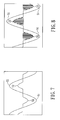
FIG 7 shows the waveform of voltage and current when the input voltage is 110 Vrms, the resistance of the current-limiting resistor is 100Ω and the duty cycle is 100%; and -
FIG 8 shows the waveform of voltage and current when the input voltage is 120 Vrms, the resistance of the current-limiting resistor is 100Ω and the duty cycle is 64%. - This disclosure can be exemplified but not limited by various embodiments as described hereinafter.
- Please refer to
FIG. 4A , which is a circuit diagram of a light adjustment circuit for AC-LED's according to a first embodiment of this disclosure. InFIG. 4A , the light adjustment circuit comprises an light adjustment unit 42 (composed of diodes D1, D2, D3, D4 and a control switch S1) and pulse width modulation (PWM)control circuit 43 to adjust the brightness of AC-LED's 44 in correspondence to variation in input AC power from anAC power supply 41 to enable each of the AC-LED's 44 to achieve a predetermined brightness. An external voltage signal Vext is compared with a triangle wave or a sawtooth wave from aramp generator 432 to obtain light adjustment signals with different duty cycles. The light adjustment signal is then transmitted to the control switch S1 to control the power delivered to the AC-LED's. - The control switch determines the value of the current delivered to the AC-LED's according to the duty cycle. Therefore, as the duty cycle of the control switch S1 increases, the control switch S1 allows larger power to be delivered to the AC-LED's to improve the AC-LED brightness. On the contrary, as the duty cycle of the control switch S1 decreases, the control switch S1 allows smaller power to be delivered to the AC-LED's to lower the AC-LED brightness. The control switch S1 is disposed between the four diodes D1, D2, D3, D4 so that the light adjustment circuit is capable of achieving light adjustment during both positive half cycle and negative half cycle.
- The
PWM control circuit 43 can be analog and comprise aramp generator 432 and acomparator 431. Theramp generator 432 is capable of generating a triangle wave or a sawtooth wave. Thecomparator 431 has a negative input terminal receiving the external voltage signal Vext and a positive input terminal connected to theramp generator 432, so that thecomparator 431 performs voltage comparison on an input ramp signal at the positive input terminal and the external voltage signal Vext at the negative input terminal so as to output a pulse width modulation (PWM) signal at an output terminal of thecomparator 431. A higher duty cycle results from a lowered external voltage signal Vext. On the contrary, as the external voltage signal Vext increases, the duty cycle is lowered. The PWM signal is transmitted to control switch S1 as a light adjustment signal to achieve light adjustment for the AC-LED's. - In addition to the analog
PWM control circuit 43 described above, thePWM control circuit 43 can also be digital and comprise a digital controller. The digital controller is capable of receiving an external voltage signal Vext that is to be processed by the digital controller to output a PWM signal. The external voltage signal Vext can be used to adjust the brightness according to variation in input AC power and the requirements of the user. - Please refer to
FIG. 5 , which is a waveform diagram for light adjustment using the light adjustment circuit inFIG. 4A . InFIG. 5 , the waveform diagram represents aninput power signal 51, an AC-LEDcurrent signal 52 and aPWM signal 53. When the input power signal (from the AC utility) 51 rises, the AC-LEDcurrent signal 52 rises. The duty cycle of thePWM signal 53 can be lowered by modulating the external voltage signal Vext to lower the power (in terms of current) delivered to the AC-LED's. Therefore, thecurrent signal 52 of the AC-LED's is decreased to achieve a predetermined brightness. On the contrary, when theinput power signal 51 falls, the AC-LEDcurrent signal 52 falls. The duty cycle of thePWM signal 53 can be increased by modulating the external voltage signal Vext to increase the power delivered to the AC-LED's. Therefore, thecurrent signal 52 of the AC-LED's is increased to achieve a predetermined brightness. When the temperature of the AC-LED's is too high, the external voltage signal Vext can be adjusted to lower the duty cycle to zero. Meanwhile, thecontrol switch S 1 is completely turned off to protect the AC-LED's. - The external voltage signal Vext can be coupled to a voltage feedback circuit, a current feedback circuit, a temperature feedback circuit or an external light adjustment signal. The external voltage signal Vext can be coupled to a voltage feedback circuit to detect the input AC power or a voltage cross the AC-LED's to monitor the AC-LED's. The external voltage signal Vext can be coupled to a current feedback circuit to detect the input AC power or a current flowing through the AC-LED's to monitor the AC-LED's. The external voltage signal Vext can be coupled to a temperature feedback circuit comprising a temperature detector and a signal transformer. The temperature detector is attached to the AC-LED's to obtain a temperature value transformed to the temperature feedback signal by the signal transformer so as to provide the PWM control circuit with the temperature feedback signal whose duty cycle is to be adjusted by the PWM control circuit. The external light adjustment signal can be analog or digital to adjust the brightness of the AC-LED's.
- Please refer to
FIG. 4B ,FIG. 4C ,FIG. 4D andFIG. 4E for a circuit diagram of a light adjustment circuit for AC-LED's according to a second, a third, a fourth and a fifth embodiments of this disclosure. InFIG. 4B , the external voltage signal Vext is coupled to a current feedback circuit. The current feedback circuit comprises acurrent detector 45 receiving acurrent feedback signal 451. Thecurrent detector 45 is connected in series with the AC-LED's 44 to obtain the value of the AC-LED current whose duty cycle is to be adjusted by thePWM control circuit 43. Similarly, inFIG. 4C , the external voltage signal Vext is coupled to a voltage feedback circuit. The voltage feedback circuit comprises avoltage detector 46 receiving avoltage feedback signal 461. Thevoltage detector 46 is connected in parallel with the AC-LED's 44 to obtain the value of the AC-LED voltage whose duty cycle is to be adjusted by thePWM control circuit 43. InFIG. 4D , the external voltage signal Vext is coupled to a temperature feedback circuit. The temperature feedback circuit comprises atemperature detector 47 and asignal transformer 471. Thetemperature detector 47 is attached to the AC-LED's 44 to obtain a temperature value transformed to atemperature feedback signal 472 by thesignal transformer 471 so as to provide thePWM control circuit 43 with thetemperature feedback signal 472 whose duty cycle is to be adjusted by thePWM control circuit 43. InFIG. 4E , the external voltage signal Vext is coupled to an analog or adigital transformer 48 receiving an external analog or a digitallight adjustment signal 481 to be transformed to anadjusted signal 482 whose duty cycle is to be adjusted by thePWM control circuit 43. -
FIG. 6 is a detailed circuit of the circuit diagram ofFIG. 4A . InFIG. 6 , acomparator 431 performs a comparison on an external voltage signal Vext sampled by an operational amplifier and a sawtooth wave to obtain signals with different duty cycles. Then, alight isolator 49 transmits the signals to the control switch S1 in thelight adjustment unit 42 to control the turn-on time of the control switch S1 to complete light adjustment for the AC-LED's. Thelight isolator 49 is disposed between thelight adjustment unit 42 and thePWM control circuit 43. -
FIG 7 and FIG. 8 show the waveform of voltage and current when the input voltage is 110 and 120 Vrms, respectively. When the input voltage is 110 Vrms, the illuminance is 1205 Lux. As the input voltage rises to 120 Vrms, the illuminance increases up to 1730 Lux. Meanwhile, the duty cycle falls from 100% to 64% to keep the illuminance at 1205 Lux. Therefore, the light adjustment circuit of this disclosure can be experimentally demonstrated by adjusting the duty cycle of the PWM signal of the control switch to achieve light adjustment for the AC-LED's. - This disclosure discloses a light adjustment circuit capable of adjusting the brightness of AC-LED's in correspondence to variation in input AC power to enable each of the AC-LED's to achieve a predetermined brightness with enhanced reliability and lifetime. Therefore, this disclosure is useful, novel and non-obvious.
- Although this disclosure has been disclosed and illustrated with reference accelerometer to particular embodiments, the principles involved are susceptible for use in numerous other embodiments that will be apparent to persons skilled in the art. This disclosure is, therefore, to be limited only as indicated by the scope of the appended claims.
Claims (10)
- A light adjustment circuit for alternating-current light emitting diodes (AC-LED's), the light adjustment circuit being connected to an AC power supply and a plurality of AC-LED's, the light adjustment circuit comprising:a light adjustment unit, being capable of modulating AC power from the AC power supply while providing the plurality of AC-LED's with the modulated AC power; anda pulse width modulation (PWM) control circuit, being capable of modulating an external voltage signal in correspondence to variation in input AC power to enable each of the AC-LED's to achieve a predetermined brightness;wherein the AC-LED's are turned off by modulating the external voltage signal to prevent the AC-LED's from being burnt out when the input AC power is too high.
- The light adjustment circuit for AC-LED's as recited in claim 1, wherein the light adjustment unit further comprises:a control switch with a duty cycle capable of determining a value of a current delivered to the AC-LED's; anda full-bridge circuit composed of four diodes;wherein the control switch is disposed between the four diodes so that the light adjustment circuit is capable of achieving light adjustment during both positive half cycle and negative half cycle.
- The light adjustment circuit for AC-LED's as recited in claim 1, wherein the PWM control circuit is an analog PWM control circuit or a digital PWM control circuit.
- The light adjustment circuit for AC-LED's as recited in claim 3, wherein the analog PWM control circuit comprises:a ramp generator, being capable of generating a triangle wave or a sawtooth wave; anda comparator, having a negative input terminal receiving the external voltage signal and a positive input terminal connected to the ramp generator, so that the comparator performs voltage comparison on an input ramp signal at the positive input terminal and the external voltage signal at the negative input terminal so as to output a pulse width modulation (PWM) signal at an output terminal of the comparator.
- The light adjustment circuit for AC-LED's as recited in claim 3, wherein the digital PWM control circuit comprises:a digital controller, being capable of receiving the external voltage signal that is to be processed by the digital controller to output a PWM signal.
- The light adjustment circuit for AC-LED's as recited in claim 1, wherein the external voltage signal is coupled to a voltage feedback circuit to detect the input AC power or a voltage cross the AC-LED's to monitor the AC-LED's.
- The light adjustment circuit for AC-LED's as recited in claim 1, wherein the external voltage signal is coupled to a current feedback circuit to detect the input AC power or a current flowing through the AC-LED's to monitor the AC-LED's.
- The light adjustment circuit for AC-LED's as recited in claim 1, wherein the external voltage signal is coupled to a temperature feedback circuit comprising a temperature detector and a signal transformer, the temperature detector being attached to the AC-LED's to obtain a temperature value transformed to a temperature feedback signal by the signal transformer so as to provide the PWM control circuit with the temperature feedback signal whose duty cycle is to be adjusted by the PWM control circuit.
- The light adjustment circuit for AC-LED's as recited in claim 1, wherein the external voltage signal is coupled to an external light adjustment signal, being analog or digital, to adjust the brightness of the AC-LED's.
- The light adjustment circuit for AC-LED's as recited in claim 1, further comprising a light isolator disposed between the light adjustment unit and the PWM control circuit.
Applications Claiming Priority (1)
| Application Number | Priority Date | Filing Date | Title |
|---|---|---|---|
| TW098130002A TWI414206B (en) | 2009-09-07 | 2009-09-07 | Light adjustment circuit for alternating-current light emitting diode |
Publications (1)
| Publication Number | Publication Date |
|---|---|
| EP2296437A1 true EP2296437A1 (en) | 2011-03-16 |
Family
ID=43087011
Family Applications (1)
| Application Number | Title | Priority Date | Filing Date |
|---|---|---|---|
| EP20090177447 Ceased EP2296437A1 (en) | 2009-09-07 | 2009-11-30 | Light adjustment circuit for alternating-current |
Country Status (3)
| Country | Link |
|---|---|
| US (1) | US8111009B2 (en) |
| EP (1) | EP2296437A1 (en) |
| TW (1) | TWI414206B (en) |
Families Citing this family (12)
| Publication number | Priority date | Publication date | Assignee | Title |
|---|---|---|---|---|
| RU2589734C2 (en) * | 2011-03-28 | 2016-07-10 | Конинклейке Филипс Н.В. | Excitation device and method for excitation of load, in particular, light-emitting diodes |
| US8330390B2 (en) * | 2011-04-11 | 2012-12-11 | Bridgelux, Inc. | AC LED light source with reduced flicker |
| US9730294B2 (en) * | 2011-11-07 | 2017-08-08 | GE Lighting Solutions, LLC | Lighting device including a drive device configured for dimming light-emitting diodes |
| US9531441B2 (en) | 2012-02-21 | 2016-12-27 | Lg Innotek Co., Ltd. | Wireless power receiver and method of managing power thereof |
| US9684037B2 (en) | 2014-05-27 | 2017-06-20 | Power Measrements, LLC | Devices and methods for testing the energy measurement accuracy, billing accuracy, functional performance and safety of electric vehicle charging stations |
| KR102277126B1 (en) | 2014-06-24 | 2021-07-15 | 삼성전자주식회사 | DRIVING DEVICE FOR LEDs AND LIGHTING DEVICE |
| US9338854B1 (en) * | 2015-02-12 | 2016-05-10 | Cooler Master (Hui Zhou) Co., Ltd. | Safety switch apparatus, universal LED tube having the safety switch apparatus, and power system of the universal LED tube |
| CN107432065B (en) * | 2015-03-26 | 2020-01-03 | 飞利浦照明控股有限公司 | LED driver circuit, lighting device and driving method |
| WO2016160798A1 (en) | 2015-03-31 | 2016-10-06 | Luxtech, Llc | Light emitting diode (led) warm on dim circuit |
| TWI571024B (en) * | 2015-08-27 | 2017-02-11 | 財團法人成大研究發展基金會 | Testing circuit system for reliability of protector |
| CN105208742A (en) * | 2015-10-23 | 2015-12-30 | 深圳迈睿智能科技有限公司 | AC LED light adjustment method and inductive light adjustment controller |
| KR101921226B1 (en) * | 2017-02-14 | 2019-02-13 | (주)이젝스 | Power supply apparatus and method therefor |
Citations (5)
| Publication number | Priority date | Publication date | Assignee | Title |
|---|---|---|---|---|
| US4955069A (en) * | 1989-03-02 | 1990-09-04 | Ionescu Adrian F | A.C. power controller with short circuit and overload protection |
| US20040206970A1 (en) | 2003-04-16 | 2004-10-21 | Martin Paul S. | Alternating current light emitting device |
| US20060284493A1 (en) * | 2005-06-15 | 2006-12-21 | Osram Sylvania Inc. | Lamp containing pulse width modulated voltage conversion circuit |
| US20080130288A1 (en) * | 2003-09-12 | 2008-06-05 | Anthony Catalano | Light Emitting Diode Replacement Lamp |
| US7489086B2 (en) | 2004-02-25 | 2009-02-10 | Lynk Labs, Inc. | AC light emitting diode and AC LED drive methods and apparatus |
Family Cites Families (8)
| Publication number | Priority date | Publication date | Assignee | Title |
|---|---|---|---|---|
| JP4399405B2 (en) * | 2005-08-25 | 2010-01-13 | 株式会社MERSTech | AC voltage controller using phase advance current |
| EP1791398A1 (en) * | 2005-11-22 | 2007-05-30 | Patent-Treuhand-Gesellschaft für elektrische Glühlampen mbH | A driving arrangement for LED cells |
| KR101345354B1 (en) * | 2006-10-06 | 2013-12-30 | 코닌클리케 필립스 엔.브이. | Light element array with controllable current sources and method of operation |
| US7800315B2 (en) * | 2007-09-21 | 2010-09-21 | Exclara, Inc. | System and method for regulation of solid state lighting |
| US7847489B2 (en) * | 2008-06-28 | 2010-12-07 | Huan-Po Lin | Apparatus and method for driving and adjusting light |
| KR101001241B1 (en) * | 2008-09-05 | 2010-12-17 | 서울반도체 주식회사 | AC LED dimmer and dimming method |
| US8410717B2 (en) * | 2009-06-04 | 2013-04-02 | Point Somee Limited Liability Company | Apparatus, method and system for providing AC line power to lighting devices |
| TWM370269U (en) * | 2009-07-27 | 2009-12-01 | Forward Electronics Co Ltd | AC LED for preventing generation of harmonic wave and stroboscopic effect |
-
2009
- 2009-09-07 TW TW098130002A patent/TWI414206B/en not_active IP Right Cessation
- 2009-11-30 US US12/627,197 patent/US8111009B2/en not_active Expired - Fee Related
- 2009-11-30 EP EP20090177447 patent/EP2296437A1/en not_active Ceased
Patent Citations (5)
| Publication number | Priority date | Publication date | Assignee | Title |
|---|---|---|---|---|
| US4955069A (en) * | 1989-03-02 | 1990-09-04 | Ionescu Adrian F | A.C. power controller with short circuit and overload protection |
| US20040206970A1 (en) | 2003-04-16 | 2004-10-21 | Martin Paul S. | Alternating current light emitting device |
| US20080130288A1 (en) * | 2003-09-12 | 2008-06-05 | Anthony Catalano | Light Emitting Diode Replacement Lamp |
| US7489086B2 (en) | 2004-02-25 | 2009-02-10 | Lynk Labs, Inc. | AC light emitting diode and AC LED drive methods and apparatus |
| US20060284493A1 (en) * | 2005-06-15 | 2006-12-21 | Osram Sylvania Inc. | Lamp containing pulse width modulated voltage conversion circuit |
Also Published As
| Publication number | Publication date |
|---|---|
| TWI414206B (en) | 2013-11-01 |
| US20110057568A1 (en) | 2011-03-10 |
| TW201110808A (en) | 2011-03-16 |
| US8111009B2 (en) | 2012-02-07 |
Similar Documents
| Publication | Publication Date | Title |
|---|---|---|
| US8111009B2 (en) | Light adjustment circuit for alternating-current light emitting diodes (AC-LED's) | |
| US8344657B2 (en) | LED driver with open loop dimming control | |
| CN102474953B (en) | Dimming device for a lighting apparatus | |
| CN101489335B (en) | Light-emitting diode driving circuit and its secondary side controller | |
| US8143800B2 (en) | Circuits and methods for driving a load with power factor correction function | |
| US9345081B2 (en) | LED driver system, controller and associated method | |
| TWI401555B (en) | Voltage-regulating circuit with input voltage detecting circuit and parallel voltage-regulating circuit system using the same | |
| US8787039B2 (en) | Hybrid adaptive power factor correction schemes for switching power converters | |
| CN203368317U (en) | High PFC constant current control device without loop compensation and voltage converter | |
| TWI442677B (en) | Power supply and controller thereof | |
| EP2496056B1 (en) | Constant-current-drive led module device | |
| US10306717B1 (en) | Flicker-free LED driving apparatus and voltage regulating method thereof | |
| EP3459168B1 (en) | An led driver and a method for driving an led load | |
| JP2011223819A (en) | Power factor improving circuit | |
| JP2015053225A (en) | LED drive circuit | |
| CN101154886A (en) | DC-DC conversion circuit and controller thereof | |
| CN114172391B (en) | Constant power reference modulation circuit, control device and chip, power supply device and method | |
| CN104124862A (en) | High-PFC constant current control device without loop compensation and voltage converter | |
| US10334673B2 (en) | Lighting system | |
| KR20190016382A (en) | Apparatus and method for improving power factor of converter for light emitting diode dimming lighting device | |
| CN102045911B (en) | Light source adjustment circuit of AC light emitting diode | |
| US12206337B2 (en) | Power conversion device and control circuit with input capacitor discharge function | |
| CN106061037A (en) | LED driving circuit with power factor correction and driver | |
| CN205584574U (en) | Dimmable switchable LED drive circuit without measuring phase angle | |
| US20230180365A1 (en) | A driving circuit, and led circuit and a driving method |
Legal Events
| Date | Code | Title | Description |
|---|---|---|---|
| PUAI | Public reference made under article 153(3) epc to a published international application that has entered the european phase |
Free format text: ORIGINAL CODE: 0009012 |
|
| AK | Designated contracting states |
Kind code of ref document: A1 Designated state(s): AT BE BG CH CY CZ DE DK EE ES FI FR GB GR HR HU IE IS IT LI LT LU LV MC MK MT NL NO PL PT RO SE SI SK SM TR |
|
| AX | Request for extension of the european patent |
Extension state: AL BA RS |
|
| 17P | Request for examination filed |
Effective date: 20110831 |
|
| 17Q | First examination report despatched |
Effective date: 20120816 |
|
| 18R | Application refused |
Effective date: 20150510 |
|
| STAA | Information on the status of an ep patent application or granted ep patent |
Free format text: STATUS: THE APPLICATION HAS BEEN REFUSED |
|
| R18R | Application refused (corrected) |
Effective date: 20150312 |